
Performance Evaluation of Electrochem's PEM Fuel Cell ...
10
Performance Evaluation of Electrochem's PEM Fuel Cell Power Plant for NASA's 2nd Generation Reusable Launch Vehicle Abstract for the 1 St International Energy Conversion Engineering Conference Michael C. Kimble'/ Electrochem, Inc. Mark Hoberecht / NASA Glenn Research Center NASA's 2"d Generation Reusable Launch Vehicle (RLV) is being developed to meet national needs for civil and commercial space access with goals of reducing the launch costs, increasing the reliability, and reducing the maintenance and operating costs. To this end, NASA has selected an all-electric capability for the RLV requiring advanced electrical power generation technology at a nominal 20 kW level with peak power capabilities six times the nominal power. The proton exchange membrane (PEM) fuel cell has been identified as a viable candidate to supply this electrical power; however, several technology aspects need to be assessed. Electrochem, Inc., under contract to NASA, has developed a breadboard power generator to address these technical issues with the goal of maximizing the system reliability while minimizing the cost and system complexity. This breadboard generator operates with dry hydrogen and oxygen gas using eductors to recirculate the gases eliminating gas humidification and blowers li-om the system. Except for a coolant pump, the system design incorporates passive components allowing the fuel cell to readily follow a duty cycle profile and that may operate at high 6: 1 peak power levels for 30 second durations. Performance data of the fuel cell stack along with system performance is presented to highlight the benefits of the fuel cell stack design and system design for the reusable launch vehicle. This is a preprint or reprint of a paper intended for presentation at a conference. Because changes may be made before formal publication, this is made available with the understanding that it will not be cited or reproducedwithout the permission of the author. ' Point of Contact: Michael Kimble ElectroChem, Inc. 400 W. Cummings Park Woburn, MA 01801 Tel: (781) 938-5300 Fax: (781) 935-6966 Email: [email protected]
Transcript of Performance Evaluation of Electrochem's PEM Fuel Cell ...

Performance Evaluation of Electrochem's PEM Fuel Cell Power Plant for NASA's 2nd Generation Reusable Launch Vehicle
Abstract for the 1 St International Energy Conversion Engineering Conference
Michael C. Kimble'/ Electrochem, Inc. Mark Hoberecht / NASA Glenn Research Center
NASA's 2"d Generation Reusable Launch Vehicle (RLV) is being developed to meet national needs for civil and commercial space access with goals of reducing the launch costs, increasing the reliability, and reducing the maintenance and operating costs. To this end, NASA has selected an all-electric capability for the RLV requiring advanced electrical power generation technology at a nominal 20 kW level with peak power capabilities six times the nominal power. The proton exchange membrane (PEM) fuel cell has been identified as a viable candidate to supply this electrical power; however, several technology aspects need to be assessed. Electrochem, Inc., under contract to NASA, has developed a breadboard power generator to address these technical issues with the goal of maximizing the system reliability while minimizing the cost and system complexity. This breadboard generator operates with dry hydrogen and oxygen gas using eductors to recirculate the gases eliminating gas humidification and blowers li-om the system. Except for a coolant pump, the system design incorporates passive components allowing the fuel cell to readily follow a duty cycle profile and that may operate at high 6: 1 peak power levels for 30 second durations. Performance data of the fuel cell stack along with system performance is presented to highlight the benefits of the fuel cell stack design and system design for the reusable launch vehicle.
This is a preprint or reprint of a paper intended for presentation at a conference. Because changes may be made before formal publication, this is made available with the understanding that it will not be cited or reproduced without the permission of the author.
' Point of Contact: Michael Kimble ElectroChem, Inc. 400 W. Cummings Park Woburn, MA 01801
Tel: (781) 938-5300 Fax: (781) 935-6966 Email: [email protected]
PERFORMANCE EVALUATION OF ELECTROCHEM’S PEM FUEL CELL POWER PLANT
FOR NASA’s 2m GENERATION REUSABLE LAUNCH VEHICLE
Michael C. Kimble Electrochem, Inc.
400 W. Cummings Park Woburn, MA
and
Mark Hoberecht NASA Glenn Research Center
2 1000 Brookpark Road Cleveland, OH
ABSTRACT
NASA’s Next Generation Launch Technology (NGLT) program is being developed to meet national needs for civil and commercial space access with goals of reducing the launch costs, increasing the reliability, and reducing the maintenance and operating costs. To this end, NASA is considering an all- electric capability for NGLT vehicles requiring advanced electrical power generation technology at a nominal 20 kW level with peak power capabilities six times the nominal power.
The proton exchange membrane (PEM) fuel cell has been identified as a viable candidate to supply this electrical power; however, several technology aspects need to be assessed. Electrochem, Inc., under contract to NASA, has developed a breadboard power generator to address these technical issues with the goal of maximizing the system reliability while minimizing the cost and system complexity.
This breadboard generator operates with dry hydrogen and oxygen gas using eductors to recirculate the gases eliminating gas humidification and blowers from the system. Except for a coolant pump, the system design incorporates passive components allowing the fuel cell to readily follow a duty cycle profile and that may operate at high 6: 1 peak power levels for 30 second durations. Performance data of the fuel cell stack along with system performance is presented to highlight the benefits of the fuel cell stack design and system design for NGLT vehicles.
INTRODUCTION
Perhaps the most successful application to date of fuel cell technology has been with NASA in powering their manned space flights. Since the early days of the US Space Program, NASA has employed fuel cells to produce electricity and water aboard spacecraft using the on-board hydrogen and oxygen reactants. The present Space Shuttle fleet uses Alkaline Fuel Cells
I American Institute of Aeronautics and Astronautics
(AFCs) despite the high costs to maintain these stacks. In order to minimize the fuel cell costs on future spacecraft, NASA is investigating replacing the AFCs with the proton exchange membrane fuel cell (PEMFC) that offers much lower maintenance costs and higher reliability. To this end, NASA is planning on using the PEM fuel cell on future NGLT vehicles, the next generation of vehicles that will replace the shuttle fleet. Electrochem, Inc., under contract to NASA Glenn Research Center, developed and
and pumps have intrinsically lower reliability than non-moving components, we selected to avoid using these type of moving components. Instead, our system uses static gas recirculation eductors instead of fans. We also designed our power plant generator to operate with dry hydrogen and oxygen gases as opposed to humidified gases that most fuel cell developers use. With our approach, our system does not require the bulky humidification sub-systems that add weight and volume to the generator and that require water pumps
evaluated a breadboard proton exchange to move water around the system. A membrane fuel cell power generator to be used on these vehicles.
APPROACH
The fuel cell power plant design for this effort focused on maximizing system reliability as opposed to having the highest stack power density, a metric that is often used by fuel cell developers. Although a high stack power density is important, an even more important metric is to have a high system power density that is our objective. With this in mind, we conducted the necessary analysis and design studies to maximize the system power density while using a minimal number of components that improves reliability and keeps costs low.
Based on our continued commercial development of fuel cell backup power systems where high reliability is a strict requirement, our system follows a “passive” balance of plant approach that has a minimal number of moving parts. Since moving parts such as compressors, fans,
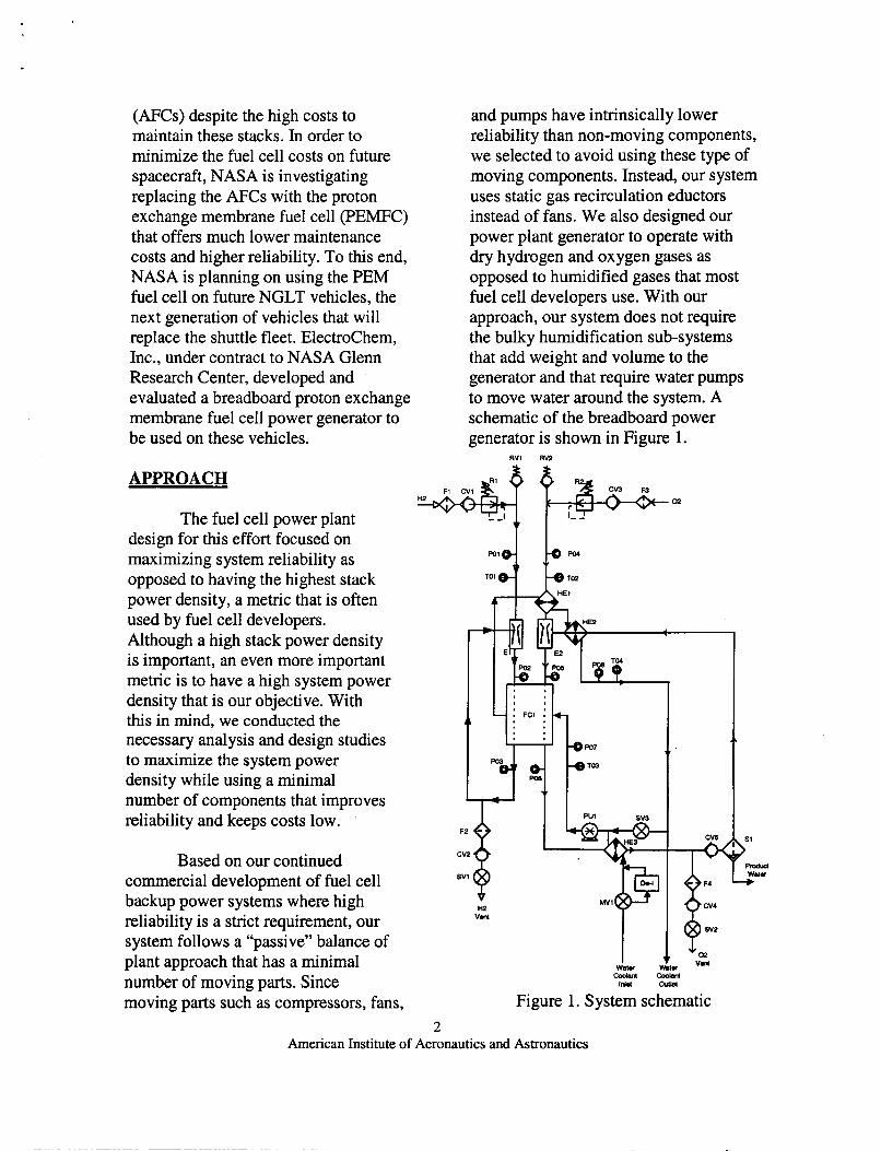
schematic of the breadboard power generator is shown in Figure 1.
RVl RV2
2 American Institute of Aeronautics and Astronautics
This power generator consists of inlet filters (F1 and F3), check valves (CV1 and CV3), regulators (Rl and RZ), and relief valves (RVl and RV2) for the hydrogen and oxygen inlet gases, respectively. The hydrogen gas flows through a static eductor or ejector (El) before entering the stack (FC1). The exit gas from the fuel cell is recirculated back into the ejector to obtain 100% fuel utilization. If purging is necessary, a solenoid (SV1) may be opened.
For the oxygen gas line, the gas is introduced through a gadwater heat exchanger (HEl) before entering a static eductor (E2) and the fuel cell stack. The oxidant exit from the stack consisting of unreacted oxygen and product water from the fuel cell reaction is cooled slightly through a gadwater heat exchanger (HE3) before entering a gadliquid phase separator ( S 1). Saturated oxygen leaves the phase separator and is heated in a gadwater heat exchanger (HE2) before being recirculated into the eductor. This oxygen line may be purged by opening up a solenoid (SV2).
The water coolant for this system is in the 48-60 "C range when entering the power generator from an external heat exchanger. A fraction of this coolant is by-passed into a deionizer unit (DE-1) to maintain high resistivity water for minimizing shunt currents. This coolant water is warmed slightly in a heat exchanger (HE3) before being introduced into the stack via a pump (PU1). The waste heat from the fuel cell is removed with this coolant stream and used to preheat the incoming oxygen gas in heat exchanger (HE1) and the recirculated saturated oxygen stream in
heat exchanger (HE2). This coolant stream is then partially directed back to the fuel cell via a mix valve (SV3) with the remaining water returning to the external heat exchanger.
A number of pressure transducers (Pxx) and thermocouples (Txx) are placed around the system for monitoring and controlling the system. With this system design approach, the only active moving component is the coolant pump with the purge solenoids and mix valve moving occasionally. Other components are static that help to increase the reliability.
RELIABILITY
Mechanical reliability predictions may be performed using a number of methods. In order of preference, the methods are analysis of part failure data history, use of empirical reliability models, analysis of stress-strength interference, and use of surrogate data sources. The optimum prediction method for this analysis would use failure history data from an identical power plant in identical operating conditions. Given the conceptual status of the power plant, no failure history exists. The complexity of the power plant also means that no single empirical model to predict the reliability of the entire power plant is available.
This analysis predicts overall system mechanical reliability by breaking the power plant into its functional components and using the best available prediction method for each component. The overall reliability is the product of the individual component reliabilities. This is a very
3 American Institute of Aeronautics and Astronautics
common method to predict reliability for complex systems given no system-wide failure history. Generally this type of prediction relies heavily on surrogate data sources that provide failure rates based on collected industry data. This is also known as a parts count. The reliability function for each component is assumed to be exponentially distributed; failures occur randomly throughout a component’s life such that the probability of failure at any time during the operating life of the component is constant. The actual reliability is defined as R(t), where R(t) = exp (-At) and h is the failure rate in failures per unit time.
The parts count method is good in that it provides a generalized measure of reliability for large, complex systems such as the power plant where the errors in individual failure rate estimates tend to average out. The method is approximate for the power plant in that it assumes constant failure rates for the components, when in fact components may wear out rapidly late in life due to corrosion and contamination from the fuel cell’s moisture-laden environment. The method is also an approximation since the failure rates from tabulated sources may not account for the NGLT’s multiple launch end-use environment. Nonetheless, the parts count is viewed as the best method for this prediction given the lack of failure history or an all- encompassing reliability model.
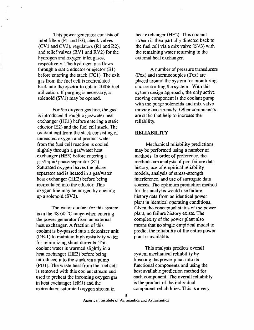
Table 1 shows the reliability summary for the breadboard generator based on the schematic shown in Figure 1. We estimate an overall reliability of 0.86 for this breadboard unit. By reducing the number of fittings in the
system, reducing the instrumentation, and reducing sources of contamination, we can increase this reliability to 0.91. Furthermore, by having one or even two redundant systems on board, we can increase the PEM fuel cell power generator reliability to over 99%.
Table 1. PEN I-----
Component Filters Check Valves Regulators Relief Valves Eductors Fuel Cell Solenoids Pump Heat Ex. Mix Valve Deionizer Phase Separator Pres. Sensors Temp. Sensors Fittings Contamination Total Reliability
;c P
QtY
-
- 4 5 2 2 2 1 2 1 3 1 1 1 8 4 50 1 -
wer Plant Rc Component Reliability 0.9970 0.9990 0.9987 0.9990 0.9990 0.9900 0.9944 0.9877 0.9990 0.9944 0.9980 0.9900 0.9964 0.9998 0.9995 0.9851
1
DURABILITY
iability Su b-Tota qeliabilit) 0.988 0.995 0.997 0.998 0.998 0.990 0.989 0.988 0.997 0.994 0.998 0.990 0.972 0.999 0.975 0.985 0.863
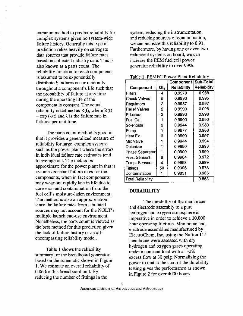
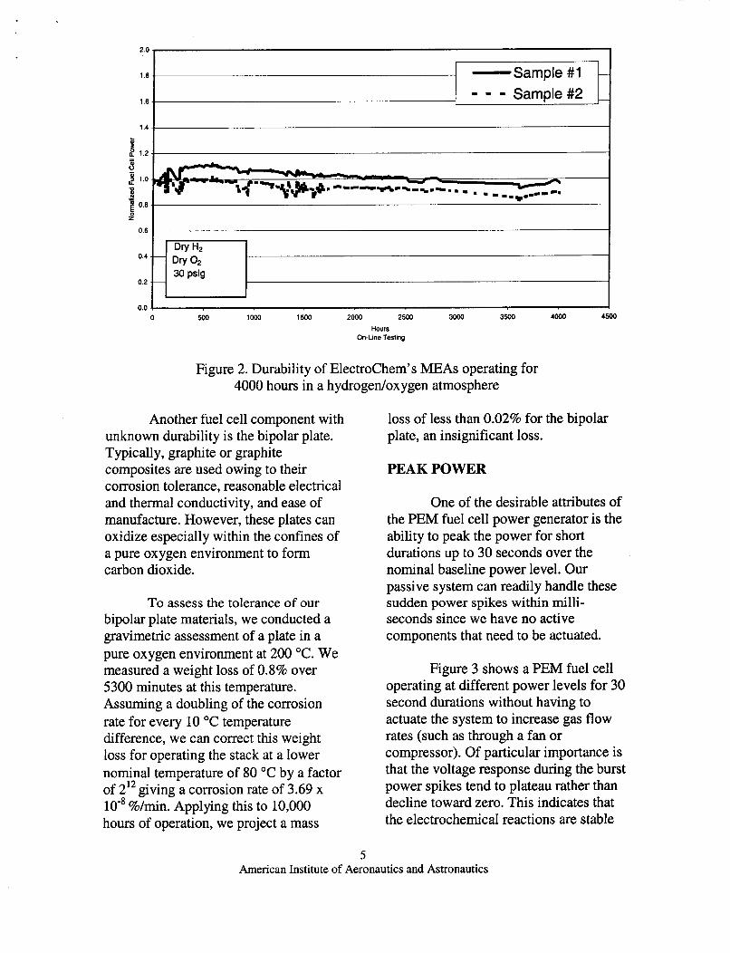
The durability of the membrane and electrode assembly to a pure hydrogen and oxygen atmosphere is imperative in order to achieve a 10,000 hour operating lifetime. Membrane and electrode assemblies manufactured by Electrochem, Inc. using the Ndion 115 membrane were assessed with dry hydrogen and oxygen gases operating under a constant load with a 1-2% excess flow at 30 psig. Normalizing the power to that at the start of the durability testing gives the performance as shown in Figure 2 for over 4000 hours.
4 American Institute of Aeronautics and Astronautics
- Sample#l -
1 1 1 Sample#2 - 1 8 -
1 8 .
1 4 .
I 2 1 2 .
0.6 -
0.4
0.2
0.0 7
Figure 2. Durability of Electrochem's MEAs operating for 4000 hours in a hydrogen/oxygen atmosphere
Dry H2 .- Dry O2
30 psig --
Another fuel cell component with unknown durability is the bipolar plate. Typically, graphite or graphite composites are used owing to their corrosion tolerance, reasonable electrical and thermal conductivity, and ease of manufacture. However, these plates can oxidize especially within the confines of a pure oxygen environment to form carbon dioxide.
To assess the tolerance of our bipolar plate materials, we conducted a gravimetric assessment of a plate in a pure oxygen environment at 200 "C. We measured a weight loss of 0.8% over 5300 minutes at this temperature. Assuming a doubling of the corrosion rate for every 10 "C temperature difference, we can correct this weight loss for operating the stack at a lower nominal temperature of 80 "C by a factor of 212 giving a corrosion rate of 3.69 x lo-* %/min. Applying this to 10,000 hours of operation, we project a mass
loss of less than 0.02% for the bipolar plate, an insignificant loss.
PEAK POWER
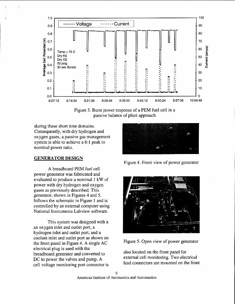
One of the desirable attributes of the PEM fuel cell power generator is the ability to peak the power for short durations up to 30 seconds over the nominal baseline power level. Our passive system can readily handle these sudden power spikes within milli- seconds since we have no active components that need to be actuated.
Figure 3 shows a PEM fuel cell operating at different power levels for 30 second durations without having to actuate the system to increase gas flow rates (such as through a fan or compressor). Of particular importance is that the voltage response during the burst power spikes tend to plateau rather than decline toward zero. This indicates that the electrochemical reactions are stable
5 American Institute of Aeronautics and Astronautics
I." I I - Voltage - - - - - - Current 1 0.9 190-
0.8 -
2 0.7 - - a - c 5 0.6 -
- 0.5 - .I- O P - 6
0.4 - E a 0.3 -
0.2 -
0.1 -
80
70
60
50 k E
40 2 30
20
10
n
h
5
"." I . - 9:07:12 9:14:24 9:21:36 9:28:48 9:36:00 9:43:12 9:50:24 9:57:36 10:04:48
Figure 3. Burst power response of a PEM fuel cell in a passive balance of plant approach
during these short time domains. Consequently, with dry hydrogen and oxygen gases, a passive gas management system is able to achieve a 6: 1 peak to nominal power ratio.
GENERATOR DESIGN
A breadboard PEM fuel cell power generator was fabricated and evaluated to produce a nominal 1 kW of power with dry hydrogen and oxygen gases as previously described. This generator, shown in Figures 4 and 5, follows the schematic in Figure 1 and is controlled by an external computer using National Instruments Labview software.
This system was designed with a an oxygen inlet and outlet port, a hydrogen inlet and outlet port, and a coolant inlet and outlet port as shown on the front panel in Figure 4. A single AC electrical plug is used with the breadboard generator and converted to DC to power the valves and pump. A cell voltage monitoring port connector is
~~~~
Figure 4. Front view of power generator
Figure 5 . Open view of power generator
also located on the front panel for external cell monitoring. Two electrical lead connectors are mounted on the front
6 American Institute of Aeronautics and Astronautics
panel that are connected to an external load.
The fuel cell stack for this generator was designed and fabricated at Electrochem, Inc. to be tolerant within a zero-gravity environment. The stack consists of 45 cells with an active area of 232 cm2 along with coolant plates throughout for thermal management control. The membrane and electrode assemblies are also manufactured by Electrochem using a Nafion 115 membrane. A photograph of the stack is shown in Figure 6.
Figure 6 . 1 kW nomind6 kW peak PEM fuel cell stack
This stack was designed to operate at a nominal 1 kW of power with the ability to peak six times to 6 kW for 30 second durations. This stack weighs 15.9 kg including the fittings and is approximately 29 cm long by 20 cm wide and 22 cm tall. Keeping in mind that the stack is designed to operate with dry hydrogen and oxygen up to 50 psig and 80 OC, the stack was designed to have lightweight bipolar plates and endplates to minimize the stack mass as the system is scaled to higher power levels in future systems.
A data acquisition and control system was developed using National Instruments hardware and software. This control software monitors the pressures and temperatures throughout the system as shown on the control screen in Figure 7 along with the cell potentials, stack current, voltage, and power. Cell voltages that are less than 0.1 volts below the average cell voltage are indicated by a red LED on the screen to alert the operator.
Two software switches are used to open and close the hydrogen and oxygen purge valves via operator intervention. The coolant pump and mix valve are automatically adjusted by the control software to maintain the fuel cell stack in the 75 to 80 "C range. User selectable screen update rates and file write rates are also featured with this system. The coolant pump can also be operated manually and even reversed to aid in filling and draining coolant from the system.
Figure 7. Graphical user interface for the PEM fuel cell power generator
7 American Institute of Aeronautics and Astronautics
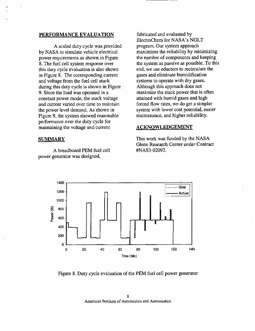
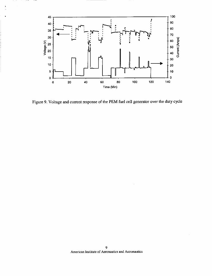
PERFORMANCE EVALUATION
A scaled duty cycle was provided by NASA to simulate vehicle electrical power requirements as shown in Figure 8. The fuel cell system response over this duty cycle evaluation is also shown in Figure 8. The corresponding current and voltage from the fuel cell stack during this duty cycle is shown in Figure 9. Since the load was operated in a constant power mode, the stack voltage and current varied over time to maintain the power level demand. As shown in Figure 9, the system showed reasonable performance over the duty cycle for maintaining the voltage and current
SUMMARY
A breadboard PEM fuel cell power generator was designed,
1400
1200
1000
800
5 n g 600
400
200
fabricated and evaluated by Electrochem for NASA’s NGLT program. Our system approach maximizes the reliability by minimizing the number of components and keeping the system as passive as possible. To this end, we use eductors to recirculate the gases and eliminate humidification systems to operate with dry gases. Although this approach does not maximize the stack power that is often attained with humid gases and high forced flow rates, we do get a simpler system with lower cost potential, easier maintenance, and higher reliability.
ACKNOWLEDGEMENT
This work was funded by the NASA Glenn Research Center under Contract #NAS3-02092.
0 20 40 60 80 100 120 140
lime (Mn)
Figure 8. Duty cycle evaluation of the PEM fuel cell power generator
8 American Institute of Aeronautics and Astronautics
100
90
80
70
45
40
35
30
15
10
5
0
- 60 E 50 5
2 40 5 0
30
C
20
10
0 0 20 40 60 80 100 120 140
Time (Min)
Figure 9. Voltage and current response of the PEM fuel cell generator over the duty cycle
9 American Institute of Aeronautics and Astronautics