Performance Evaluation of An Innovative-Vapor- Compression ...
13
Aceh International Journal of Science and Technology, 1 (1): 1-13 April 2012 ISSN: 2088-9860 1 Performance Evaluation of An Innovative-Vapor- Compression-Desalination System 1 Mirna R. Lubis and 2 Mark T. Holtzaple 1 Chemical Engineering Department, Engineering Faculty, Syiah Kuala University Jl. Syech Abdurrauf No. 7, Darussalam, Banda Aceh, 23111 2 Artie McFerin Department of Chemical Engineering TAMU, College Station, Texas 1 Email: [email protected] Abstract – Two dominant desalination methods are reverse osmosis (RO) and multi-stage flash (MSF). RO requires large capital investment and maintenance, whereas MSF is too energy-intensive. Innovative system of vapor compression desalination is proposed in this study. Comprehensive mathematics model for evaporator is also described. From literature study, it is indicated that very high overall-heat-transfer coefficient for evaporator can be obtained at specific condition by using dropwise condensation in the steam side, and pool boiling in the liquid side. Smooth titanium surface is selected in order to increase dropwise condensation, and resist corrosion. To maximize energy efficiency, a cogeneration scheme of a combined cycle consisting of gas turbine, boiler heat recovery, and steam turbine that drives compressor is used. The resource for combined cycle is relatively too high for the compressor requirement. Excess power can be used to generate electricity for internal and/or external consumptions, and sold to open market. Four evaporator stages are used. Evaporator is fed by seawater, with assumption of 3.5% salt contents. Boiling brine (7% salt) is boiled in low pressure side of the heat exchanger, and condensed vapor is condensed in high pressure side of the heat exchanger. Condensed steam flows at velocity of 1.52 m/s, so that it maximize the heat transfer coefficient. This unit is designed in order to produce 10 million gallon/day, and assumed it is financed with 5%, 30 years of passive obligation. Three cases are evaluated in order to determine recommended condition to obtain the lowest fixed capital investment. Based on the evaluation, it is possible to establish four-stage unit of mechanical vapor compression distillation with capital $31,723,885. Keywords: Desalination, dropwise condensation, heat exchanger, StarRotor compressor, vapor compression distillation. Introduction Desalination aims to produce potable water form seawater, brackish water, or treated waste water. Among water treatment technologies, it is one of the most efficient thermal distillation processes used to reduce the broadest range of water contaminant. Mechanical vapor compression is modern method that produces potable water with acceptable energy efficiency (Ejjeh, 2001). Following World War II, the vapor compression distillers were used in oil production in remote area. Larger unit could produce 200,000 gallons per day. The installations had four identical units operating in parallel. The original design had one rotor fitted with a set of blades having the inducer section in a single piece. The up-graded design is based on two rotors housing the inducer blades allowing for more efficient configuration. A number of modifications have been incorporated on the shroud, vapor ducts, diffusion section, instrumentation, and the number of evaporators to improve the performance. Sheet-shell heat exchanger is key technology in the mechanical-vapor-compression-desalination system. The heat exchanger consists of new assembly, which combines conventional plate-and-frame appearance and shell-and-tube heat exchanger. The heat exchanger could be used in order to exchange sensible heat as well as latent heat. Latent heat exchanger could be part of multi effect evaporator that operates at lower temperature and pressure. Alternatively, the evaporator could be part of vapor compression evaporator. Multi effect evaporator used operates at lower pressure and temperature. Steam from high pressure evaporator boils water in adjacent low pressure. The compressor draws vapor from the low pressure evaporator, forces, and returns it to high pressure evaporator. The salt water has to be degassed before it is fed into evaporator. Low pressure steam from steam turbine discharge could be added to evaporator where pressure from discharged steam and the evaporator is the most suitable. While overall heat transfer coefficient is obtained, the heat exchanger's surface could be known, and also the cost. The disadvantages of the mechanical vapor compression system (Al-Juwayhel, 1997) include use of high electrical energy, flow rate limitations on the vapor compression range, maintenance and spare part requirements. The disadvantage limits the use of the mechanical vapor compression
Transcript of Performance Evaluation of An Innovative-Vapor- Compression ...

Aceh International Journal of Science and Technology, 1 (1): 1-13 April 2012
ISSN: 2088-9860
1
Performance Evaluation of An Innovative-Vapor- Compression-Desalination System
1Mirna R. Lubis and 2Mark T. Holtzaple
1Chemical Engineering Department, Engineering Faculty, Syiah Kuala University Jl. Syech Abdurrauf No. 7, Darussalam, Banda Aceh, 23111
2Artie McFerin Department of Chemical Engineering TAMU, College Station, Texas 1Email: [email protected]
Abstract – Two dominant desalination methods are reverse osmosis (RO) and multi-stage flash (MSF). RO requires large capital investment and maintenance, whereas MSF is too energy-intensive. Innovative system of vapor compression desalination is proposed in this study. Comprehensive mathematics model for evaporator is also described. From literature study, it is indicated that very high overall-heat-transfer coefficient for evaporator can be obtained at specific condition by using dropwise condensation in the steam side, and pool boiling in the liquid side. Smooth titanium surface is selected in order to increase dropwise condensation, and resist corrosion. To maximize energy efficiency, a cogeneration scheme of a combined cycle consisting of gas turbine, boiler heat recovery, and steam turbine that drives compressor is used. The resource for combined cycle is relatively too high for the compressor requirement. Excess power can be used to generate electricity for internal and/or external consumptions, and sold to open market. Four evaporator stages are used. Evaporator is fed by seawater, with assumption of 3.5% salt contents. Boiling brine (7% salt) is boiled in low pressure side of the heat exchanger, and condensed vapor is condensed in high pressure side of the heat exchanger. Condensed steam flows at velocity of 1.52 m/s, so that it maximize the heat transfer coefficient. This unit is designed in order to produce 10 million gallon/day, and assumed it is financed with 5%, 30 years of passive obligation. Three cases are evaluated in order to determine recommended condition to obtain the lowest fixed capital investment. Based on the evaluation, it is possible to establish four-stage unit of mechanical vapor compression distillation with capital $31,723,885. Keywords: Desalination, dropwise condensation, heat exchanger, StarRotor compressor, vapor compression distillation.
Introduction
Desalination aims to produce potable water form seawater, brackish water, or treated waste water. Among water treatment technologies, it is one of the most efficient thermal distillation processes used to reduce the broadest range of water contaminant. Mechanical vapor compression is modern method that produces potable water with acceptable energy efficiency (Ejjeh, 2001). Following World War II, the vapor compression distillers were used in oil production in remote area. Larger unit could produce 200,000 gallons per day. The installations had four identical units operating in parallel. The original design had one rotor fitted with a set of blades having the inducer section in a single piece. The up-graded design is based on two rotors housing the inducer blades allowing for more efficient configuration. A number of modifications have been incorporated on the shroud, vapor ducts, diffusion section, instrumentation, and the number of evaporators to improve the performance.
Sheet-shell heat exchanger is key technology in the mechanical-vapor-compression-desalination system. The heat exchanger consists of new assembly, which combines conventional plate-and-frame appearance and shell-and-tube heat exchanger. The heat exchanger could be used in order to exchange sensible heat as well as latent heat. Latent heat exchanger could be part of multi effect evaporator that operates at lower temperature and pressure. Alternatively, the evaporator could be part of vapor compression evaporator. Multi effect evaporator used operates at lower pressure and temperature. Steam from high pressure evaporator boils water in adjacent low pressure. The compressor draws vapor from the low pressure evaporator, forces, and returns it to high pressure evaporator. The salt water has to be degassed before it is fed into evaporator.
Low pressure steam from steam turbine discharge could be added to evaporator where pressure from discharged steam and the evaporator is the most suitable. While overall heat transfer coefficient is obtained, the heat exchanger's surface could be known, and also the cost. The disadvantages of the mechanical vapor compression system (Al-Juwayhel, 1997) include use of high electrical energy, flow rate limitations on the vapor compression range, maintenance and spare part requirements. The disadvantage limits the use of the mechanical vapor compression

Aceh International Journal of Science and Technology, 1 (1): 1-13 April 2012
ISSN: 2088-9860
2
system in countries with limited fossil, nuclear, or hydro. It also limits the operation of the mechanical vapor compression system to low brine temperature. This results in a larger heat transfer area for the heat exchanger, which increases the energy requirement, and therefore the investment cost. Because the critical cost parameter is fixed cost (amortization) and energy cost (Anonymous, 2000), this research focus is in order to reduce energy requirement by introducing multi-effect evaporator, and developing new latent heat exchanger. Holtzapple and Noyes (2004) arrange system illustrated in their Disclosure of Invention (Figure 1). Degassed feed is fed to evaporator that operates at the highest pressure (Evaporator 4). The system uses "combined cycle" machine, consisting of gas turbine (Brayton cycle) and steam turbine (Rankine cycle). Waste heat from gas turbine is used to make steam, so that it strengthens the steam turbine. Both gas turbine and steam turbine will strengthen the compressor.
Holtzapple and Noyes (2004) have arranged new sheet shell heat exchanger (Lubis, 2011) as used in this research. The configuration has short diagonal cut that enables the formation of small peak. At high pressure chamber, the baffle causes flow area more decreased, which enables relatively constant velocity through the heat exchanger. The flow finally compress out gasses that are condensable. Channel number per pass is selected in order to achieve low pressure drop. In low pressure chamber, liquid enters from bottom part, and boils because of heat exchange through the wall. Vapor resulted exits from the top.
For high pressure side of sheet-shell heat exchanger, the objective is in order to produce dropwise condensation. This could be increased by using titanium layers toward carbon steel as proposed in this research, surface coated by gold (Griffith and Lee, 1967) or titanium plate (Rose, 1967). Titanium surface also reduce impurities and avoid corrosion because of seawater (Rose, 1967). Holtzapple and Noyes (2004) targets T = 5.56oC as temperature difference in every heat exchanger of vapor compression evaporator. An extensive review on this matter (Haslego and Polley, 2002) shows that this number is suitable temperature difference. Furthermore, literature (O'Bara et al., 1967) suggested average velocity of 1.52 m/s at high-pressure steam side.
Experiment conducted by Dollof et al. (1969) indicated influence of pressure (and vapor temperature) on heat transfer coefficient of steam side. O'Bara, Killian, and Roblee also indicated that Ts = 2.3oC, large heat transfer coefficient is obtained at vapor velocity around 1.52 m/s. Ruckenstein and Metiu (1965) have used a model to estimate heat transfer coefficient for dropwise condensation on solid surface. Their model considers heat moved through drops and film, which dynamically break the solid surface. The heat transfer coefficient is proportional to drop fraction toward total area and thermal conductivity of liquid film as much of 0.3934 Btu/(h·ft·oF). Based on study that has been carried out, this research is aimed to analyze performance of a desalination system that has been designed by considering all designed data above and consists of four evaporators in order to determine capital investment of saturated steam compression. Over the past several years, the cost of desalting still cannot compete with the cost of fresh water that it requires minimal treatment to make it potable. Though many methods have been proposed to desalt seawater, only a few have been developed commercially. Therefore, the investment proposed in this research is expected to be able to give contribution to production of a unit of potable water with low cost. Materials and Methods
Degassed seawater is fed to evaporators that relate in parallel in order to obtain evaporator temperature requirement (Figure 1). The flow is between 147.5 kg/s and 144.57 kg/s. Four evaporator stages are used, each with various T = 2, 4, 6oF and 7% brine (S = 70 g/kg). This S is substituted in activity formula (Emerson and Jamieson, 1967) as follows:
(1) where; p = vapor pressure of salt water p0 = vapor pressure of water h = -2.1609 × 10⁻⁴ j = -3.5012 × 10⁻⁷ S = salinity (70 g salt/kg seawater)
Figure 2 shows the nomenclature to identify temperature and pressure of each stage of the evaporator. In order to ensure dropwise condensation, maximum pressure at steam side is set as much of 827.4 kPa gauge (120 psig). This value was chosen to give agreement with results obtained by other investigators (Dolloff et al., 1969). Saturated steam is fed to the first stage at 120 psig (176.7oC) and recovered from the final stage at 158.63oC. For T = 6oF, temperature at point C becomes 6oF less than temperature at point A, whereas vapor pressure of water is 8,471 atm from steam table.

Aceh International Journal of Science and Technology, 1 (1): 1-13 April 2012
ISSN: 2088-9860
3
Figure 1. Desalination System (Holtzapple and Noyes, 2004)
Therefore, the pressure in point C can be calculated from equation 1. The pressure obtained is the same as
the pressure at point A in stage 2. Similarly, pressure and temperature in each stage can be determined for each temperature difference. The flow rate is calculated for every evaporator as required by production. Estimated range of seawater temperature is 21.1 – 26.2oC. The number of condensation as required by flow rate or production is calculated in accordance with mass balance. The seawater feed is 3.5% salt (xf = 35 g/kg) and the following brine concentration (xb) is obtained: 20, 50, 70, dan 100 g/kg. The fouling factor is not available (the surface is assumed clean by raising brush balls. The heat transfer coefficient ia around 0.14 MW/(m2 · K). In this experiment, sea water moves at velocity of 1.52 m/s in gauge tubes ¾ in, with condensing steam at the outside. The material construction code is API-ASME code.
Titanium plate surface with thickness of 0.007 in is used in order to achieve dropwise condensation, the evaporator is constructed with elastomeric gasket, and carbon steel vessel coated with epoxy or titanium layers to protect it from corrosion on seawater side. The distance of center to center among adjacent plates is 0.25 inch. Standard plate dimension is 2.4 m × 2.4 m. Vessel shell thickness is 29.6 mm. It is based on recommended design equation for a vessel under internal pressure (Peters et al., 2003) as follows:
(2) where; P = Maximum allowable pressure = 910.1 kPa ri = Inside radius of shell before corrosion allowance is added = 2 m Sm = Maximum allowable working stress (88.350 kPa for carbon steel SEA J412) Ej = Efficiency of joints = 0.85 (spot examined joints) Cc = Allowance for corrosion = 0

Aceh International Journal of Science and Technology, 1 (1): 1-13 April 2012
ISSN: 2088-9860
4
m v C A m s
vapor steam
E
D B m b m w
Figure 2. Flows in latent heat exchanger
The sensible heat exchanger for the evaporator inlet flow and the entering seawater feed is divided in two
parts: one corresponds to the sensible heat exchanger between the exiting distillate and 50% of the seawater feed, and the other corresponds to the sensible heat transfer between the exiting brine and 50% of the seawater feed. To determine the price of the sensible heat exchanger, first a mass balance and an enthalpy balance are performed for each evaporator. The data are used to compute both the sensible heat exchanger area and the latent heat exchanger area. For dry centrifugal compressor, isentropic compressor work is calculated as follows:
(3) where; W = compressor work (J/kg) p1 = input compressor pressure (Pa) p2 = output compressor pressure (Pa) v1 = specific volume of steam at compressor inlet (m3/kg) k = isentropic constant = Cp / Cv = 1.3 or steam H2 = specific enthalpy of compressor exit (J/kg) H1 = specific enthalpy of compressor inlet (J/kg) c = isentropic efficiency of compressor = 0.85 (assumed)
Work supplied to the compressor increases the pressure and temperature. The compressor is relatively small at flow that is passed, so that it is adiabatic, it means a small number of energy is lost while heat exchange is out of the compressor. The objective is in order to increase gas pressure by using work as less as possible, which is possibly completed by making the compression process reversible. Work required in reversibly isothermal compression is less than that carried out in reversibly adiabatic compression. If the steam temperature is maintained close to the suction temperature by injecting water, the process becomes close to isothermal. Conventional centrifugal compressor does not enable water injection because high velocity blades could be damaged because of collision with the drops. Therefore, this research uses StarRotor compressor that operates at lower velocity and has strong component that could be resistant to liquid injection. StarRotor compressor uses gerotor that is positive shear apparatus. For water injection case, compressor work W is calculated (Holtzapple and Noyes, 2004) as follows:
(4) where;
= vapor enthalpy at compressor output (2) (J/kg) = vapor enthalpy at compressor input (1) (J/kg)
= liquid enthalpy at compressor input (J/kg)

Aceh International Journal of Science and Technology, 1 (1): 1-13 April 2012
ISSN: 2088-9860
5
c = compressor efficiency = 0.85 (assumed) x = the amount of water injection that evaporates in compressor.
(5) where;
= entropy of liquid water at compressor inlet (J/(kg·K)) = entropy of steam at compressor inlet (J/(kg·K)) = entropy of steam at compressor exit (J/(kg·K)) Gas turbine is used in order to supply the compressor and generator work requirement. The Mars® gas
turbine is selected because it has been engineered for very high reliability and durability as well as ease of maintenance. Like Solar's other gas turbine families, Mars gas turbines are available for compressor, generator, and mechanical-drive applications. The gas turbine power output is 11,190 kW with fuel requirements of 10,600 kJ/kWh. Steam turbine is selected according to the steam turbine operating conditions such as inlet temperature steam at 673.15 K and 4.2403 MPa, outlet temperature steam at 319.26 K and 0.010135 MPa. After an isentropic expansion, the saturated vapor quality can be calculated as follows:
(6) where; x = saturated vapor quality Sl = entropy of superheated steam (kJ/(kg·K)) S2l = entropy of saturated liquid (kJ/(kg·K)) S2v = entropy of saturated steam (kJ/(kg·K)) The energy recovered from the steam turbine is as follows:
(7) where; W = energy recovered from steam turbine H1t = enthalpy of superheated steam (kJ/kg) H2t = xH2v + (1 – x)H2l (kj/kg) Therefore the total power for the proposed combined-cycle system is power from gas turbine added by power from steam turbine. To determine the price of Heat Recovery Boiler and Pumps, both are selected to handle a total of 0.876 m3/s of seawater (3.5% concentrated feed). This rate is based on distilled flow produced i.e. 50% of the seawater feed or 10,000,000 gallons/day (3.45 × 10⁶ lbm/h or 0.4356 m3/s). The shaft work of each pump is calculated as follows:
(8)

Aceh International Journal of Science and Technology, 1 (1): 1-13 April 2012
ISSN: 2088-9860
6
where; W0 = shaft work (kW) H = total dynamic head (kPa) mv = mass flow rate (kg/s) ρseawater = 1,021.90 kg/m3 pump = pump efficiency = 0.85 Distillate and brine discharges from the sensible heat exchanger do not need pumping. Even though both flows lose pressure in the heat exchanger, they still can flow out. The discharge pressure required is the sum of the pressure drop in the sensible heat exchanger plus the vapor pressure in the latent heat exchanger. The price is obtained from Reference (Ettouney et al., 2002). All pumps receive a correction factor of 1.6 because the pressure exceeds 1,035 kPa. In addition, a factor of 1.26 is used for anti-corrosion material for all pumps used in the seawater environment. Based on design and formula of the desalination system, performance and the capital cost are analyzed while producing water as much of 10 million gallon/day. Results and Discussion
Figure 3 indicates overall heat transfer coefficient that is accordance with condensation temperature and temperature difference of heat transfer, T, between condensing steam side and boiling liquid side. Overall heat transfer coefficient U approaches optimal maximum value 53,585 Btu/(h·ft2·oF) at overall temperature difference T = 6oF. Even though high heat transfer coefficient value could be obtained in theory, constant value of 24,900 Btu/(h·ft2·oF) has been used in technical design. To verify this value, an investigation is being prepared by the author.
Data presented in this research is obtained by using 10 million gal/day of seawater feed. This unit has heat exchanger sheets that are made of titanium 0.007 inch. Data obtained from this research results in heat transfer coefficient value (U) that is suitable to analytical estimation. Once the overall heat transfer coefficient is obtained, the area of the heat exchanger can be known and consequently its cost. Because of the low temperature differential, the compression energy cost is low. The unit has been used sporadically. Testing this unit with tap water and sodium chloride solution 5000 ppm causes very thin scale layers of calcium carbonate precipitates in vaporizing side of the rotors of the last two effects. There is no effort is made in order to separate scale from the surface. High brine concentration in the last two effects also gives additional resistant to heat flow across the film solution as a result of viscosity increasing and thermal conductivity decreasing of the brine. This factor is believed to cause U values are a little lower than that predicted. Figure 4 indicates system limit for overall energy balance. Compressor work (W) will enter to the system and go
out as thermal energy that is brought out by distillate and the brine . Therefore, energy balance is:
Assume T = Tb = Ts

Aceh International Journal of Science and Technology, 1 (1): 1-13 April 2012
ISSN: 2088-9860
7
Figure 3. Calculated overall heat transfer coefficient
This temperature difference states temperature increasing of distillate and brine. In addition, this increasing is
approached temperature in sensible heat exchanger. The temperature difference is proportional to W/m; the proporsionality constant is indicated in Table 1. The result is observed so that at concentration of 7% and low T (among 2 and 6oF), the work requirement of compressor shaft is between 14 and 29 MJ/m3 that is acceptable range. Compressor in this unit is centrifugal StarRotor compressor. It is selected because while compared to centrifugal compressor, StarRotor gerotor compressor has technical benefit as follows: StarRotor gerotor compressor is cheaper ($450.000 vs $3.000.000). StarRotor gerotor compressor could retain toward water injection that makes the compression close to
isothermal that requires less work. StarRotor gerotor compressor could be designed in accordance with particular compression requirement. StarRotor gerotor compressor is efficient throughout broad range of operational condition.
The volumetric capacity is directly proportional to velocity and rather inversely proportional to pressure increasing because of back leakage of vapor in room between horse and its lobe. Three cases have been studied as indicated in Table 2.
Figure 4. Overall energy balance
Total mass balance: ms + mb = mf (6)

Aceh International Journal of Science and Technology, 1 (1): 1-13 April 2012
ISSN: 2088-9860
8
Salt mass balance: mf xf = mb xb (7) Where;
Table 1. Proporsionality constant in temperature change equation
xf (g/kg) xb (g/kg) Cpb (kJ/(kg · K)) Cps (kJ/(kg · K))
35 50 3.917 4.209 0.07491
35 70 3.822 4.209 0.12450
35 100 3.689 4.209 0.16197
35 150 3.521 4.209 0.18937

Aceh International Journal of Science and Technology, 1 (1): 1-13 April 2012
ISSN: 2088-9860
9
Table 2. Cases used in vapor compression Cases A B C
Tcond (oF) 6 4 2
Tsens (oF) 5.85 4.5 3.15
Salinity (g/kg) 70 70 70
Number of stages 4 4 4
Compressor energy (kJ/m3 distillate)
28.873 20.329 14.320
Basically, input energy to compressor motor consists of energy lost in electrical motor, energy lost in steering
belt, energy lost because of friction, and energy given to steam during compression. Figure 5 indicated compressor work for dry compressor at condenser temperature 176.7 oC as salinity function for six conditions: 0 oC, 1 oC, 2o C, 3 oC, 4 oC, and 5 oC. For every vapor compressed by compressor in 4-stage system, the unit produces 70 g/kg brine, so that at 6oF (3.3 oC) energy required by every product unit from the 4-stage unit is 30.2 kWh/thousand gallon (29 MJ/m3 distillate). The temperature is appropriate to reduce the energy because the lower condenser temperature, the higher compression energy required.
Figure 6 indicates compressor work for dry compressor at condenser temperature of 120oC. For 70 g/kg brine salinity produced at 3.3 oC, the compression work required is as much of 32.7 kWh/thousand gallon. Comparing the result to that at condenser temperature 176.7 oC, it is recommended to operate vapor compression unit at máximum temperature that is 176.7 oC in order to reduce compression energy. However, wet compressor has less work requirement, so that only wet compressor is assessed in Cases B and C. For case B, the work compressor is indicated in Figure 7. It is necessary to note here that a mechanical-vapor-compression unit of conventional single stage, and vapor compression unit of four stages that operate at the same temperature difference, compressor energy at multi stages is less than the energy in single stage because of salinity increasing in every stage compared to that of mechanical-vapor compression unit of conventional single stage. This fact indirectly states that work required by every product unit from four-stage vapor compression unit is less than that of conventional single-stage of mechanical-vapor-compression unit for the same T value regardless the evaporator type. As example of work calculation, assume situation required in order to recover 93 percent of water from various feed salinity in mechanical-vapor-compression unit that operates at average temperature 176.7 oC. For simplicity and data availability on sea salt solution, the feed is assumed to have sea water composition. Then, the situation will need compression energy that can be calculated by using Equation 4 and the results are indicated in Figure 7.
For case C, correlation of number of stages to inlet volume of compressor is indicated in Figure 8. Inlet volume of compressor is in the range of 67.16 m3 vapor/m3 distillate up to 222.97 m3 vapor/m3 distillate. It seems here that the inlet volume of compressor is around 118.6 m3 vapor/m3 liquid and higher while the stage number is less than 2. This is caused by the fact that energy consumption by rotors descends as a result of the high condensate rate, and specific energy consumed by the rotors descends as indicated in Figure 9. Comparing Figure 9 to Figure 7, it is clear that for 4 stages, compressor shaft work at T of latent heat exchanger 2 oF is less than that for single stage at T = 4 oF. However, it is not efficient to use the condition to operate unit of mechanical vapor compression distillation because the area of distillate sensible heat exchanger becomes larger. Figure 8 also indicates that for case C, it is not appropriate to use 4 stages because, it is clearly seen that the optimum condition to use minimum gas flow is while the number of stages is two.

Aceh International Journal of Science and Technology, 1 (1): 1-13 April 2012
ISSN: 2088-9860
10
Figure 5. Compression work of desalination at condenser temperature of 176.7 oC
Figure 6. Compression work of desalination at condenser temperature 120 oC
Figure 7. Work of wet compressor shaft (T of latent heat exchanger = 4 oF, Seawater feed = 3.5%, Brine = 7%, Inlet T of heat exchanger = 174 oC)

Aceh International Journal of Science and Technology, 1 (1): 1-13 April 2012
ISSN: 2088-9860
11
Figure 8. Gas flow at inlet compressor (T of latent heat exchanger = 2 oF, Seawater feed = 3.5%, Brine = 7%, Inlet T of heat exchanger = 175.5 oC)
Figure 9. Work of wet compressor shaft (T of latent heat exchanger = 2 oF, Seawater feed = 3.5%, Brine solution = 7%, Inlet T of heat exchanger = 446.53 K)
Figure 9 indicates correlation of number of stages to compressor work required to produce distillate water
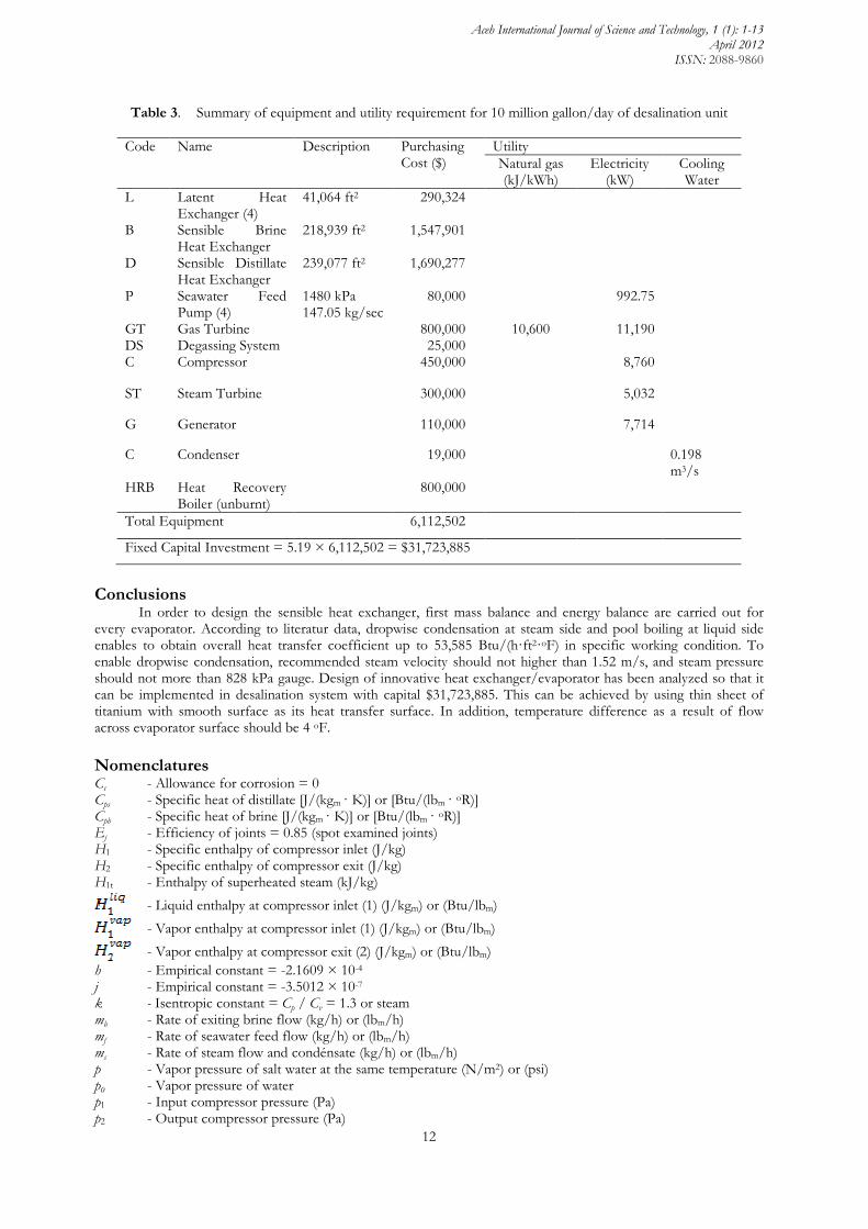
with brine concentration 70 g/kg seawater. For 4 stages, the compressor shaft work is as much of 14,320 kJ/m3, whereas for single stage, compressor work is as much of 13,915 kJ/m3. If rotor design is developed, and brine salinity is as much of 5%, specific energy consumption by the rotors calculated from equation 4 is believed to be able to achieve 11,535 kJ/m3 or less, and total specific energy consumption by compressor and the rotors will be lower while using seawater whose salinity is as much of 3.5%. However, the area of latent heat exchanger required for temperature difference of 2 oF is quite larger than that for temperature difference 4 oF, which means the condition becomes more costly. Therefore, fixed capital investment is calculated only for case B which is considered as the most efficient condition for the system. Table 3 summarizes equipment required in innovative vapor-compression-desalination unit for recommended case B. This table gives utility requirement for this unit operating. The unit consists of four latent heat exchangers, four sensible heat exchangers for brine and distillate, and four pumps. Table 3 also indicates Lang Factor component used as much of 5.19 in order to estimate total Project cost from equipment cost. However, factor 2.2 is generally used for total project cost, equipment cost, and pipeline installed in order to determine unexpected cost. The cost is not estimation because it is a base for fund proposal. The cost resource is in accordance with technical estimation.
Aceh International Journal of Science and Technology, 1 (1): 1-13 April 2012
ISSN: 2088-9860
12
Table 3. Summary of equipment and utility requirement for 10 million gallon/day of desalination unit
Code Name Description Purchasing Cost ($)
Utility Natural gas (kJ/kWh)
Electricity (kW)
Cooling Water
L Latent Heat Exchanger (4)
41,064 ft2 290,324
B Sensible Brine Heat Exchanger
218,939 ft2 1,547,901
D Sensible Distillate Heat Exchanger
239,077 ft2 1,690,277
P Seawater Feed Pump (4)
1480 kPa 147.05 kg/sec
80,000 992.75
GT Gas Turbine 800,000 10,600 11,190 DS Degassing System 25,000 C Compressor 450,000 8,760
ST Steam Turbine 300,000 5,032
G Generator 110,000 7,714
C Condenser 19,000 0.198 m3/s
HRB Heat Recovery Boiler (unburnt)
800,000
Total Equipment 6,112,502
Fixed Capital Investment = 5.19 × 6,112,502 = $31,723,885
Conclusions In order to design the sensible heat exchanger, first mass balance and energy balance are carried out for every evaporator. According to literatur data, dropwise condensation at steam side and pool boiling at liquid side enables to obtain overall heat transfer coefficient up to 53,585 Btu/(h·ft2·oF) in specific working condition. To enable dropwise condensation, recommended steam velocity should not higher than 1.52 m/s, and steam pressure should not more than 828 kPa gauge. Design of innovative heat exchanger/evaporator has been analyzed so that it can be implemented in desalination system with capital $31,723,885. This can be achieved by using thin sheet of titanium with smooth surface as its heat transfer surface. In addition, temperature difference as a result of flow across evaporator surface should be 4 oF. Nomenclatures Cc - Allowance for corrosion = 0 Cps - Specific heat of distillate [J/(kgm · K)] or [Btu/(lbm · oR)] Cpb - Specific heat of brine [J/(kgm · K)] or [Btu/(lbm · oR)] Ej - Efficiency of joints = 0.85 (spot examined joints) H1 - Specific enthalpy of compressor inlet (J/kg) H2 - Specific enthalpy of compressor exit (J/kg) H1t - Enthalpy of superheated steam (kJ/kg)
- Liquid enthalpy at compressor inlet (1) (J/kgm) or (Btu/lbm) - Vapor enthalpy at compressor inlet (1) (J/kgm) or (Btu/lbm) - Vapor enthalpy at compressor exit (2) (J/kgm) or (Btu/lbm)
h - Empirical constant = -2.1609 × 10⁻⁴ j - Empirical constant = -3.5012 × 10⁻⁷ k - Isentropic constant = Cp / Cv = 1.3 or steam mb - Rate of exiting brine flow (kg/h) or (lbm/h) mf - Rate of seawater feed flow (kg/h) or (lbm/h) ms - Rate of steam flow and condénsate (kg/h) or (lbm/h) p - Vapor pressure of salt water at the same temperature (N/m2) or (psi) p0 - Vapor pressure of water p1 - Input compressor pressure (Pa) p2 - Output compressor pressure (Pa)

Aceh International Journal of Science and Technology, 1 (1): 1-13 April 2012
ISSN: 2088-9860
13
P - Maximum allowable pressure = 910.1 kPa ri - Inside radius of shell before corrosion allowance is added = 2 m S - Salinity (g salt/kg seawater) Sl - Entropy of superheated steam (kJ/(kg·K)) S2l - Entropy of saturated liquid (kJ/(kg·K)) S2v - Entropy of saturated steam (kJ/(kg·K)) Sm - Maximum allowable working stress (88.350 kPa for carbon steel SEA J412)
- Entropy of liquid water at compressor inlet (J/(kg·K)) - Entropy of steam at compressor inlet (J/(kg·K)) - Entropy of steam at compressor exit (J/(kg·K))
Tb - Boiling temperature of the seawater (K) or (oF) Tf - Temperature of the seawater feed (K) or (oF) Ts - Steam temperature (K) or (oR) x - Fraction amount of injection wáter that evaporates in the compressor xb - Fraction amount of salt in brine xf - Fraction amount of salt in seawater feed T - Overall heat transfer temperature differential (K) or (oF) Tcond - Overall heat transfer temperature differential in latent heat exchanger (K or oF) Tsens - Overall heat transfer temperature differential in sensible heat exchanger (K, oF) v1 - Specific volume of steam at compressor inlet (m3/kg) W - Compressor work (J/kg) Wt - Energy recovered from steam turbine x - Saturated vapor quality c - Compressor efficiency Acknowledgements
The writer gratefully thanks to Dr. Jorge Horacio Juan Lara Ruiz from Texas A&M University for all support and very valuable discussion regarding this research. References Al-Juwayhel, F., El-Dessouky, H., and Ettouney, H. (1997). Analysis of single-effect evaporator desalination systems
combined with vapor compression heat pumps. Desalination, 114: 253-275. Anonymous. (2000). Examining the economics of seawater desalination using the DEEP code. Technical Document
1186, International atomic Energy Agency, Vienna, Austria. Anonymous. (2005). Solar turbines, mars 100 compressor Set. http://mysolar.cat.com/cda/layout?m=41428&x=7,
13 December 2007. Dolloff, J. B., Metzger, N. H., and Roblee, L. H. S. Jr. (1969). Dropwise condensation of steam at elevated pressures.
Chem. Eng. Sci., 24: 571-583. Ejjeh, G. (2001). Desalination, a reliable source of new water. International Desalination Association, Belgium. Ettouney, H. M.,. El-Dessouky, H. T., and Gowing, P. J. (2002). Evaluating the economics of desalination. CEP
magazine, http://cepmagazine.org, 31 December 2002. Emerson, W. H., and Jamieson, D. T. (1967). Some physical properties of sea water in various concentrations.
Desalination, 3: 213-224. Griffith, P., and Lee, M. S. (1967). The effect of surface thermal properties and finish on dropwise condensation.
Int. J. Heat Mass Transfer, 10: 697. Haslego, C., and Polley, G. (2002). Compact heat exchanger Part 1: Designing plate and frame heat exchangers, CEP
magazine, http://cepmagazine.org, 30 September 2002. Holtzapple, M., and Noyes, G. (2004). Advanced vapor-compression evaporator and heat exchanger system.
Disclosure of Invention, Department of Chemical Engineering, Texas A&M University. Lubis, M. R. (2011). Desalination using vapor-compression distillation. Lambert Academic Publishing, Germany. O'Bara, J. T., Killian, E. S., and Roblee, L. H. S. Jr. (1969). Dropwise condensation of steam at atmospheric and
above pressures. Chem. Eng. Sci., 22: 1305. Peters, M. S., Timmerhaus, K. D., and West, R. E. (2003). Plant design and economics for chemical engineers, 5th
ed., McGraw Hill, New York, NY. Rose, J. W. (1967). On the mechanism of dropwise condensation. Int. J. Heat Mass Transfer, 10: 755. Ruckestein, E., and Metiu, H. (1965). On dropwise condensation on a solid surface. Chem. Eng. Sci., 20: 173.