Performance Evaluation of a Wavelength Division ... · Dense Wavelength Division Multiplexing...
15
IJSRD - International Journal for Scientific Research & Development| Vol. 4, Issue 04, 2016 | ISSN (online): 2321-0613 All rights reserved by www.ijsrd.com 368 Performance Evaluation of a Wavelength Division Multiplexed (WDM) Free Space Optical Communication Link Under Diverse Weather Conditions Using Different Modulation Formats Salwinder Singh 1 Shivinder Devra 2 Karamdeep Singh 3 1,2,3 Department of Electronics Technology 1,2,3 Guru Nanak Dev University, Amritsar, Punjab, India Abstract— In this paper, simulative analysis of 10Gbps DWDM system link with FSO channel using different modulation format under different weather condition has been performed. A 16×10 DWDM system has been analyzed with 1nm channel spacing and the effect of variation in input power and transmission distance is observed in terms of Q-factor values of received channels. From the study of variation in input power in the scenario of different weather condition (clear, haze, rain and fog) the best modulation format has been identified. It has been observed that DBNRZ modulation format is best result than other modulation formats. Similarly in the case of while varying link distance under different weather conditions, the best modulation format has been recognized. It has been observed that CSNRZ modulation format is better result than the other modulation formats. The BER performance of all received signals is also discussed. Key words: DWDM, CSNRZ, CSRZ, DBNRZ, MDBNRZ, MDBRZ, Weather Conditions I. INTRODUCTION\ Free space optics is a wireless communication technology which utilizes light for transmission of data through the air in the similar manner as the fiber optics uses a fiber cable. Free space optics is having the same capabilities as that of fiber optics, but at a very lower cost and very fast deployment speed [1]. It has advantages high speed, low cost, high bandwidth, quick installation high security and also license-free longer range spectrum [2]. But in fiber case have problem that is dispersion, nonlinear impacts in a transmission line but not in the FSO channel [3-5-6] and FSO system is also severely limited by the four wav mixing effect [4, 28]. Free space optics work on the principal of laser driven technology which use light source and detectors to transmit and receive information, through the atmosphere same as the Fiber Optic communication cable [2]. The rapidly growing volumes of data network traffic driven by the growth of the internet, service providers are always increase the fiber capacity and wavelength spectral efficiency in their networks [7]. In wavelength division multiplexed network, the fiber bandwidth is divided into multiple bands called wave lengths [8]. The WDM enables us to multiplex more than one wavelength channels on a single stand of fiber. So it is preferred for transmission over long distance transport network. So amount of traffic network is increases [9]. Due to traffic of signals Dense Wavelength Division Multiplexing (DWDM) technology is developed to support tremendous bandwidth [10].Typical Dense Wavelength Division Multiplexing (DWDM) networks of today employ 50GHz channel spacing, as per the international standard [11]. DWDM device combine the output from several optical transmitters for transmission across a single optical fiber. At the receiving end, another DWDM separate the combined optical signals and passes to an optical receiver and only one of optical fiber or FSO channel used between DWDM devices [12].Transmission capacity C of a DWDM fiber optic communication system is given by[13] C=B*K*D (1) Where B is the bit rate, K is the optical signal bandwidth and D is the channel density which is reciprocal of channel spacing. Capacity of system increased if increasing the bit rate in individual wavelength, expanding the optical signal bandwidth and decreasing the channel spacing. DWDM system is a transparent system. It is a bit- rate and modulation format independent scheme. It increases the capacity of existing networks by transmitting many channels with minimum optical power per channel simultaneously on a single fiber [13]. An effective DWDM system should have the following characteristics-[14]: a) Large capacity. b) System upgrade can maximize existing investment protection. c) High reliability and flexibility of networking. d) Compatible all optical exchange. An effective DWDM system should have the following Merits [15]: a) Less fiber core to transmit and receive high capacity data. b) A Single core fiber cable could divide into multiple channels. c) Easy network expansion, especially for limited fiber resource no need extra fiber but adds wavelength Low cost for expansion because of no need to replace many components such as optical amplifiers. An effective DWDM system should have the following Limitations [15]: a) Not cost effective for low channels, low channel recommend CWDM. b) Complicated transmitter and receivers. c) The frequency domain involved in the network design and management, increase the difficulty for implementation. In the section 2, literature survey is discussed. In the section 3, different modulation formats along with their optical spectrum are described. In section 4, explains different weather condition. In section 5, explains simulation setup and parameters. In section 6, results have been reported for various formats, case -1 power variation from 11dbm to 20dbm, case -2 length variations in different weather condition, Case-3 performance Of BER. In section 7 conclusions are made.
Transcript of Performance Evaluation of a Wavelength Division ... · Dense Wavelength Division Multiplexing...
IJSRD - International Journal for Scientific Research & Development| Vol. 4, Issue 04, 2016 | ISSN (online): 2321-0613
All rights reserved by www.ijsrd.com 368
Performance Evaluation of a Wavelength Division Multiplexed (WDM)
Free Space Optical Communication Link Under Diverse Weather
Conditions Using Different Modulation Formats Salwinder Singh1 Shivinder Devra2 Karamdeep Singh3
1,2,3Department of Electronics Technology 1,2,3
Guru Nanak Dev University, Amritsar, Punjab, IndiaAbstract— In this paper, simulative analysis of 10Gbps
DWDM system link with FSO channel using different
modulation format under different weather condition has
been performed. A 16×10 DWDM system has been
analyzed with 1nm channel spacing and the effect of
variation in input power and transmission distance is
observed in terms of Q-factor values of received channels.
From the study of variation in input power in the scenario of
different weather condition (clear, haze, rain and fog) the
best modulation format has been identified. It has been
observed that DBNRZ modulation format is best result than
other modulation formats. Similarly in the case of while
varying link distance under different weather conditions, the
best modulation format has been recognized. It has been
observed that CSNRZ modulation format is better result
than the other modulation formats. The BER performance of
all received signals is also discussed.
Key words: DWDM, CSNRZ, CSRZ, DBNRZ, MDBNRZ,
MDBRZ, Weather Conditions
I. INTRODUCTION\
Free space optics is a wireless communication technology
which utilizes light for transmission of data through the air
in the similar manner as the fiber optics uses a fiber cable.
Free space optics is having the same capabilities as that of
fiber optics, but at a very lower cost and very fast
deployment speed [1]. It has advantages high speed, low
cost, high bandwidth, quick installation high security and
also license-free longer range spectrum [2]. But in fiber case
have problem that is dispersion, nonlinear impacts in a
transmission line but not in the FSO channel [3-5-6] and
FSO system is also severely limited by the four wav mixing
effect [4, 28]. Free space optics work on the principal of
laser driven technology which use light source and detectors
to transmit and receive information, through the atmosphere
same as the Fiber Optic communication cable [2]. The
rapidly growing volumes of data network traffic driven by
the growth of the internet, service providers are always
increase the fiber capacity and wavelength spectral
efficiency in their networks [7]. In wavelength division
multiplexed network, the fiber bandwidth is divided into
multiple bands called wave lengths [8]. The WDM enables
us to multiplex more than one wavelength channels on a
single stand of fiber. So it is preferred for transmission over
long distance transport network. So amount of traffic
network is increases [9]. Due to traffic of signals Dense
Wavelength Division Multiplexing (DWDM) technology is
developed to support tremendous bandwidth [10].Typical
Dense Wavelength Division Multiplexing (DWDM)
networks of today employ 50GHz channel spacing, as per
the international standard [11]. DWDM device combine the
output from several optical transmitters for transmission
across a single optical fiber. At the receiving end, another
DWDM separate the combined optical signals and passes to
an optical receiver and only one of optical fiber or FSO
channel used between DWDM devices [12].Transmission
capacity C of a DWDM fiber optic communication system is
given by[13]
C=B*K*D (1)
Where B is the bit rate, K is the optical signal
bandwidth and D is the channel density which is reciprocal
of channel spacing. Capacity of system increased if
increasing the bit rate in individual wavelength, expanding
the optical signal bandwidth and decreasing the channel
spacing. DWDM system is a transparent system. It is a bit-
rate and modulation format independent scheme. It increases
the capacity of existing networks by transmitting many
channels with minimum optical power per channel
simultaneously on a single fiber [13].
An effective DWDM system should have the
following characteristics-[14]:
a) Large capacity.
b) System upgrade can maximize existing investment
protection.
c) High reliability and flexibility of networking.
d) Compatible all optical exchange.
An effective DWDM system should have the following
Merits [15]:
a) Less fiber core to transmit and receive high capacity
data.
b) A Single core fiber cable could divide into multiple
channels.
c) Easy network expansion, especially for limited fiber
resource no need extra fiber but adds wavelength Low
cost for expansion because of no need to replace many
components such as optical amplifiers.
An effective DWDM system should have the following
Limitations [15]:
a) Not cost effective for low channels, low channel
recommend CWDM.
b) Complicated transmitter and receivers.
c) The frequency domain involved in the network design
and management, increase the difficulty for
implementation.
In the section 2, literature survey is discussed. In
the section 3, different modulation formats along with their
optical spectrum are described. In section 4, explains
different weather condition. In section 5, explains simulation
setup and parameters. In section 6, results have been
reported for various formats, case -1 power variation from
11dbm to 20dbm, case -2 length variations in different
weather condition, Case-3 performance Of BER. In section
7 conclusions are made.
Performance Evaluation of a Wavelength Division Multiplexed (WDM) Free Space Optical Communication Link Under Diverse Weather Conditions Using Different Modulation Formats
(IJSRD/Vol. 4/Issue 04/2016/093)
All rights reserved by www.ijsrd.com 369
II. LITERATURE SURVEY
Ajay K. Sharma et al. (2009) studied robustness of various
modulation formats at 40Gbps. The performance is
categorized using Q-factor. They investigated non linearity
and noise show robustness up to 450 km at 40Gbos. At high
rate, CRZ show better results than NRZ, RZ and CSRZ [16].
Farukh Nadeem et al., (2009) investigate the
weather effects on Hybrid FSO/RF Communication Link.
FSO is the most prefer among different communication
technologies when a high data rate link is required but
suffers from different weather effects like fog, rain, snow
and clouds in the earth atmosphere. Hybrid network, a
combination of FSO main link and radio frequency back up
link, is a used to overcome the atmospheric attenuations.
The simulation results show that for frequencies greater than
40 GHz have the rain attenuations are higher for GHz
frequency links as compared to the prime FSO link. The
combination of FSO with 40 GHz backup link would
provide good backup data rates though availability achieved
would be under heavy rain [17].
E. Ciaramella et al., (2009) described the novel
idea of 1.28 Terabit/s (32 x 40Gbit/s) WDM transmission
systems for free space optical communications. In this paper
investigates the improvement in the signal power
stabilization is achieved by saturated EDFAs. The results
show that when the terminals are fed by common WDM
signals they allow enough power budget and margins to
support a record high capacity transmission (32×40Gbit/s),
with an enormous improvement of stability means six hours
with no error burst [18].
Jagjit Singh Malhotra et al., (2010) investigate the
Performance analysis of NRZ, RZ, CRZ and CSRZ data
formats in 10Gbps. In this paper investigate the performance
of NRZ, RZ, CRZ and CSRZ data formats analyzed on the
basis of bit error rate (BER), Q2 (dB), OSNR, eye opening
performance metrics. The results show that CRZ and CSRZ
modulation format is perform better as compared to NRZ
and RZ. The CSRZ has optimal performance according to
performance metrics [19].
T. Sabapathi et al., (2011) described the analysis of
bottlenecks in DWDM fiber optic communication system.
The author described the Stimulated Brillouin Scattering
(SBS), Stimulated Raman Scattering (SRS) and Four Wave
Mixing (FWM) in DWDM. In this paper analyze the effect
of SBS, phase mismatching and wavelength spacing [20].
Ross Saunders et al., (2011) studied the concept of
Coherent DWDM (CDWDM) technology for high speed
optical communications. In this paper studied that an initial
implementation of 40 Gb/s coherent systems using dual
polarization quadrature phase shift keying (DP-QPSK) after
that development in the new systems running at 100Gb/s
DP-QPSK data rate. In the CDWDM poses some significant
challenges in terms such as electro-optic, DSP, ADC/DAC
design and fiber nonlinearity [21].
It has been observed from the study of available
literature that most of researchers have contributed towards
enhancement of fiber optic communication links by different
modulation formats, whereas none of the precision
researchers have investigated the performance of free space
optical communication link by employing different
modulation formats.
III. DIFFERENT MODULATION FORMATS
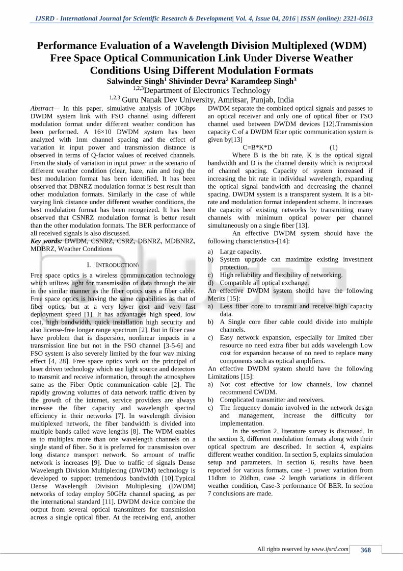
A. Carrier Suppressed Non return to Zero (CSNRZ)
Format: -
CSNRZ format has high tolerance to the mixed effect of the
self-phase modulation and group velocity dispersion (GVD)
and has narrower shape of the optical spectrum than the
conventional RZ format. Fig-(1a) shows the schematic
diagram of CSNRZ transmitter. In it the NRZ signal after
MZ modulator goes through the phase modulator driven by
analog sine wave generator at the frequency equal to half the
bit rate. That will introduce zero phase shifts between the
two adjacent bits and the spectrum will be modified such
that the central peak at the carrier frequency is suppressed as
shown in the Fig-(1b).
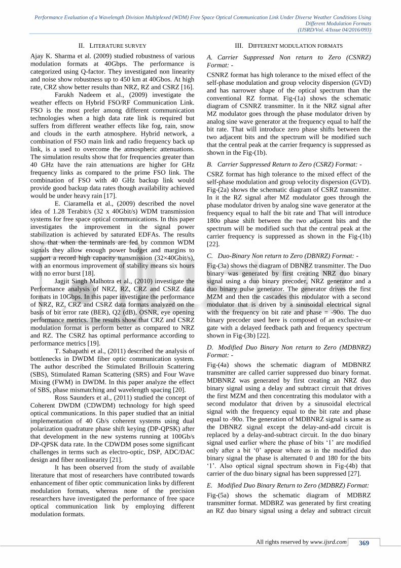
B. Carrier Suppressed Return to Zero (CSRZ) Format: -
CSRZ format has high tolerance to the mixed effect of the
self-phase modulation and group velocity dispersion (GVD).
Fig-(2a) shows the schematic diagram of CSRZ transmitter.
In it the RZ signal after MZ modulator goes through the
phase modulator driven by analog sine wave generator at the
frequency equal to half the bit rate and That will introduce
180o phase shift between the two adjacent bits and the
spectrum will be modified such that the central peak at the
carrier frequency is suppressed as shown in the Fig-(1b)
[22].
C. Duo-Binary Non return to Zero (DBNRZ) Format: -
Fig-(3a) shows the diagram of DBNRZ transmitter. The Duo
binary was generated by first creating NRZ duo binary
signal using a duo binary precoder, NRZ generator and a
duo binary pulse generator. The generator drives the first
MZM and then the cascades this modulator with a second
modulator that is driven by a sinusoidal electrical signal
with the frequency on bit rate and phase = -90o. The duo
binary precoder used here is composed of an exclusive-or
gate with a delayed feedback path and frequency spectrum
shown in Fig-(3b) [22].
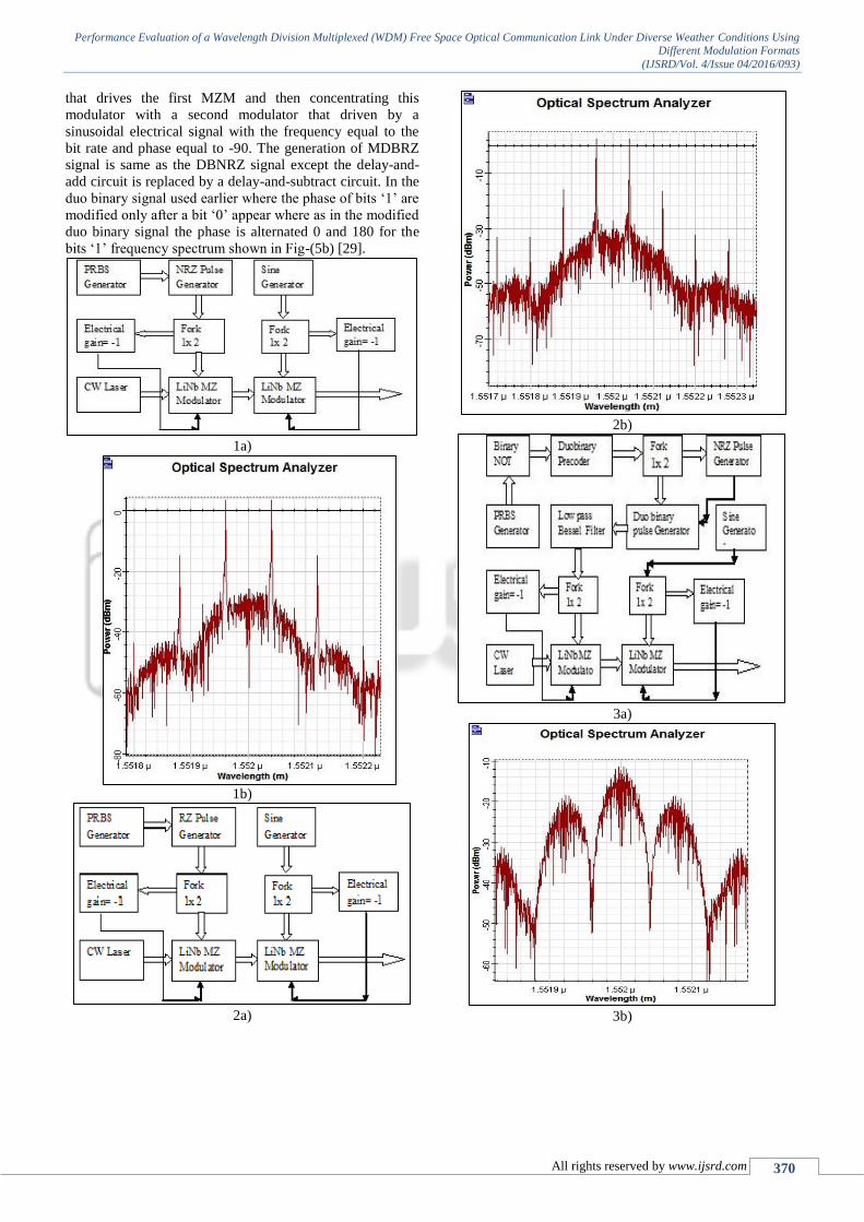
D. Modified Duo Binary Non return to Zero (MDBNRZ)
Format: -
Fig-(4a) shows the schematic diagram of MDBNRZ
transmitter are called carrier suppressed duo binary format.
MDBNRZ was generated by first creating an NRZ duo
binary signal using a delay and subtract circuit that drives
the first MZM and then concentrating this modulator with a
second modulator that driven by a sinusoidal electrical
signal with the frequency equal to the bit rate and phase
equal to -90o. The generation of MDBNRZ signal is same as
the DBNRZ signal except the delay-and-add circuit is
replaced by a delay-and-subtract circuit. In the duo binary
signal used earlier where the phase of bits ‘1’ are modified
only after a bit ‘0’ appear where as in the modified duo
binary signal the phase is alternated 0 and 180 for the bits
‘1’. Also optical signal spectrum shown in Fig-(4b) that
carrier of the duo binary signal has been suppressed [27].
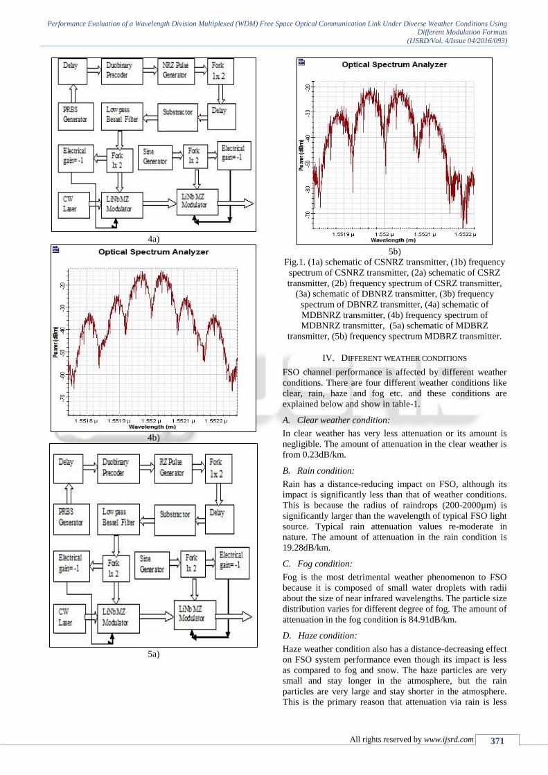
E. Modified Duo Binary Return to Zero (MDBRZ) Format:
Fig-(5a) shows the schematic diagram of MDBRZ
transmitter format. MDBRZ was generated by first creating
an RZ duo binary signal using a delay and subtract circuit
Performance Evaluation of a Wavelength Division Multiplexed (WDM) Free Space Optical Communication Link Under Diverse Weather Conditions Using Different Modulation Formats
(IJSRD/Vol. 4/Issue 04/2016/093)
All rights reserved by www.ijsrd.com 370
that drives the first MZM and then concentrating this
modulator with a second modulator that driven by a
sinusoidal electrical signal with the frequency equal to the
bit rate and phase equal to -90. The generation of MDBRZ
signal is same as the DBNRZ signal except the delay-and-
add circuit is replaced by a delay-and-subtract circuit. In the
duo binary signal used earlier where the phase of bits ‘1’ are
modified only after a bit ‘0’ appear where as in the modified
duo binary signal the phase is alternated 0 and 180 for the
bits ‘1’ frequency spectrum shown in Fig-(5b) [29].
1a)
1b)
2a)
2b)
3a)
3b)
Performance Evaluation of a Wavelength Division Multiplexed (WDM) Free Space Optical Communication Link Under Diverse Weather Conditions Using Different Modulation Formats
(IJSRD/Vol. 4/Issue 04/2016/093)
All rights reserved by www.ijsrd.com 371
4a)
4b)
5a)
5b)
Fig.1. (1a) schematic of CSNRZ transmitter, (1b) frequency
spectrum of CSNRZ transmitter, (2a) schematic of CSRZ
transmitter, (2b) frequency spectrum of CSRZ transmitter,
(3a) schematic of DBNRZ transmitter, (3b) frequency
spectrum of DBNRZ transmitter, (4a) schematic of
MDBNRZ transmitter, (4b) frequency spectrum of
MDBNRZ transmitter, (5a) schematic of MDBRZ
transmitter, (5b) frequency spectrum MDBRZ transmitter.
IV. DIFFERENT WEATHER CONDITIONS
FSO channel performance is affected by different weather
conditions. There are four different weather conditions like
clear, rain, haze and fog etc. and these conditions are
explained below and show in table-1.
A. Clear weather condition:
In clear weather has very less attenuation or its amount is
negligible. The amount of attenuation in the clear weather is
from 0.23dB/km.
B. Rain condition:
Rain has a distance-reducing impact on FSO, although its
impact is significantly less than that of weather conditions.
This is because the radius of raindrops (200-2000µm) is
significantly larger than the wavelength of typical FSO light
source. Typical rain attenuation values re-moderate in
nature. The amount of attenuation in the rain condition is
19.28dB/km.
C. Fog condition:
Fog is the most detrimental weather phenomenon to FSO
because it is composed of small water droplets with radii
about the size of near infrared wavelengths. The particle size
distribution varies for different degree of fog. The amount of
attenuation in the fog condition is 84.91dB/km.
D. Haze condition:
Haze weather condition also has a distance-decreasing effect
on FSO system performance even though its impact is less
as compared to fog and snow. The haze particles are very
small and stay longer in the atmosphere, but the rain
particles are very large and stay shorter in the atmosphere.
This is the primary reason that attenuation via rain is less
Performance Evaluation of a Wavelength Division Multiplexed (WDM) Free Space Optical Communication Link Under Diverse Weather Conditions Using Different Modulation Formats
(IJSRD/Vol. 4/Issue 04/2016/093)
All rights reserved by www.ijsrd.com 372
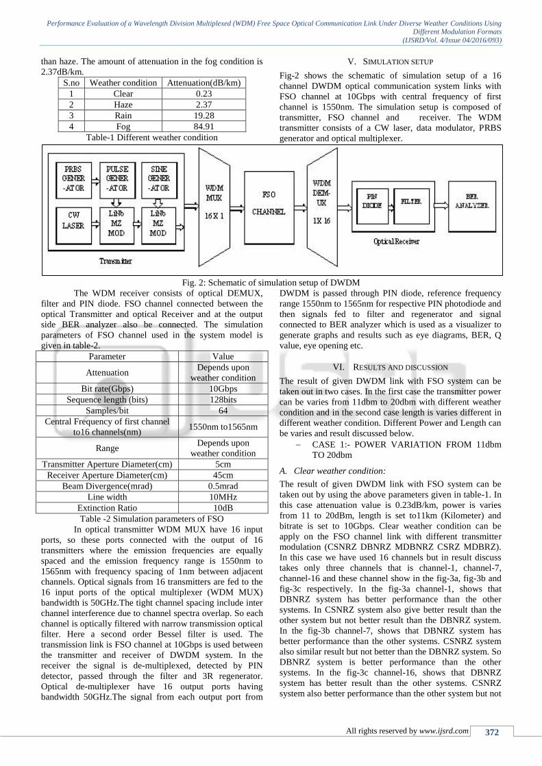
than haze. The amount of attenuation in the fog condition is
2.37dB/km.
S.no Weather condition Attenuation(dB/km)
1 Clear 0.23
2 Haze 2.37
3 Rain 19.28
4 Fog 84.91
Table-1 Different weather condition
V. SIMULATION SETUP
Fig-2 shows the schematic of simulation setup of a 16
channel DWDM optical communication system links with
FSO channel at 10Gbps with central frequency of first
channel is 1550nm. The simulation setup is composed of
transmitter, FSO channel and receiver. The WDM
transmitter consists of a CW laser, data modulator, PRBS
generator and optical multiplexer.
Fig. 2: Schematic of simulation setup of DWDM
The WDM receiver consists of optical DEMUX,
filter and PIN diode. FSO channel connected between the
optical Transmitter and optical Receiver and at the output
side BER analyzer also be connected. The simulation
parameters of FSO channel used in the system model is
given in table-2.
Parameter Value
Attenuation Depends upon
weather condition
Bit rate(Gbps) 10Gbps
Sequence length (bits) 128bits
Samples/bit 64
Central Frequency of first channel
to16 channels(nm) 1550nm to1565nm
Range Depends upon
weather condition
Transmitter Aperture Diameter(cm) 5cm
Receiver Aperture Diameter(cm) 45cm
Beam Divergence(mrad) 0.5mrad
Line width 10MHz
Extinction Ratio 10dB
Table -2 Simulation parameters of FSO
In optical transmitter WDM MUX have 16 input
ports, so these ports connected with the output of 16
transmitters where the emission frequencies are equally
spaced and the emission frequency range is 1550nm to
1565nm with frequency spacing of 1nm between adjacent
channels. Optical signals from 16 transmitters are fed to the
16 input ports of the optical multiplexer (WDM MUX)
bandwidth is 50GHz.The tight channel spacing include inter
channel interference due to channel spectra overlap. So each
channel is optically filtered with narrow transmission optical
filter. Here a second order Bessel filter is used. The
transmission link is FSO channel at 10Gbps is used between
the transmitter and receiver of DWDM system. In the
receiver the signal is de-multiplexed, detected by PIN
detector, passed through the filter and 3R regenerator.
Optical de-multiplexer have 16 output ports having
bandwidth 50GHz.The signal from each output port from
DWDM is passed through PIN diode, reference frequency
range 1550nm to 1565nm for respective PIN photodiode and
then signals fed to filter and regenerator and signal
connected to BER analyzer which is used as a visualizer to
generate graphs and results such as eye diagrams, BER, Q
value, eye opening etc.
VI. RESULTS AND DISCUSSION
The result of given DWDM link with FSO system can be
taken out in two cases. In the first case the transmitter power
can be varies from 11dbm to 20dbm with different weather
condition and in the second case length is varies different in
different weather condition. Different Power and Length can
be varies and result discussed below.
CASE 1:- POWER VARIATION FROM 11dbm
TO 20dbm
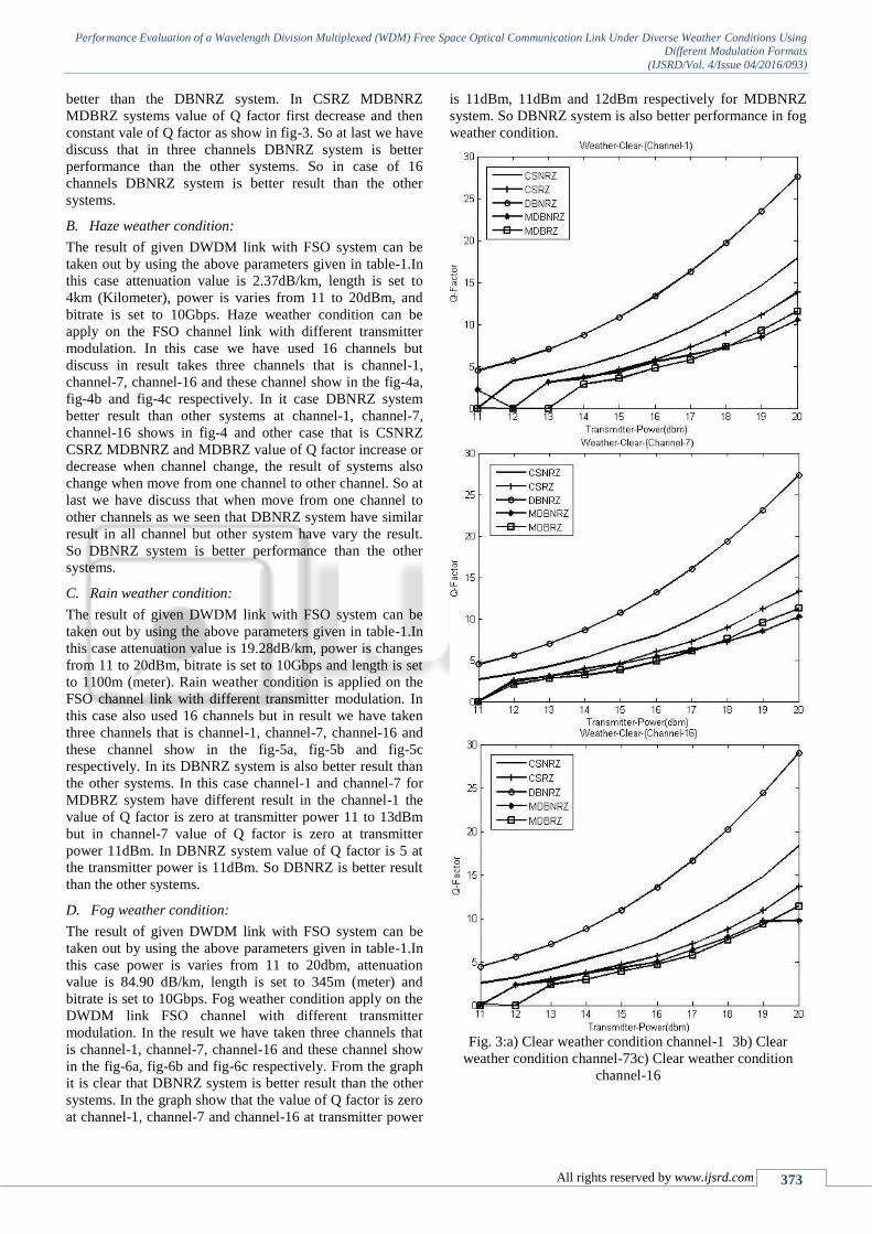
A. Clear weather condition:
The result of given DWDM link with FSO system can be
taken out by using the above parameters given in table-1. In
this case attenuation value is 0.23dB/km, power is varies
from 11 to 20dBm, length is set to11km (Kilometer) and
bitrate is set to 10Gbps. Clear weather condition can be
apply on the FSO channel link with different transmitter
modulation (CSNRZ DBNRZ MDBNRZ CSRZ MDBRZ).
In this case we have used 16 channels but in result discuss
takes only three channels that is channel-1, channel-7,
channel-16 and these channel show in the fig-3a, fig-3b and
fig-3c respectively. In the fig-3a channel-1, shows that
DBNRZ system has better performance than the other
systems. In CSNRZ system also give better result than the
other system but not better result than the DBNRZ system.
In the fig-3b channel-7, shows that DBNRZ system has
better performance than the other systems. CSNRZ system
also similar result but not better than the DBNRZ system. So
DBNRZ system is better performance than the other
systems. In the fig-3c channel-16, shows that DBNRZ
system has better result than the other systems. CSNRZ
system also better performance than the other system but not
Performance Evaluation of a Wavelength Division Multiplexed (WDM) Free Space Optical Communication Link Under Diverse Weather Conditions Using Different Modulation Formats
(IJSRD/Vol. 4/Issue 04/2016/093)
All rights reserved by www.ijsrd.com 373
better than the DBNRZ system. In CSRZ MDBNRZ
MDBRZ systems value of Q factor first decrease and then
constant vale of Q factor as show in fig-3. So at last we have
discuss that in three channels DBNRZ system is better
performance than the other systems. So in case of 16
channels DBNRZ system is better result than the other
systems.
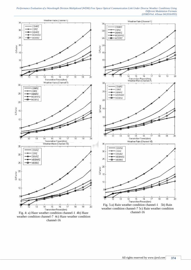
B. Haze weather condition:
The result of given DWDM link with FSO system can be
taken out by using the above parameters given in table-1.In
this case attenuation value is 2.37dB/km, length is set to
4km (Kilometer), power is varies from 11 to 20dBm, and
bitrate is set to 10Gbps. Haze weather condition can be
apply on the FSO channel link with different transmitter
modulation. In this case we have used 16 channels but
discuss in result takes three channels that is channel-1,
channel-7, channel-16 and these channel show in the fig-4a,
fig-4b and fig-4c respectively. In it case DBNRZ system
better result than other systems at channel-1, channel-7,
channel-16 shows in fig-4 and other case that is CSNRZ
CSRZ MDBNRZ and MDBRZ value of Q factor increase or
decrease when channel change, the result of systems also
change when move from one channel to other channel. So at
last we have discuss that when move from one channel to
other channels as we seen that DBNRZ system have similar
result in all channel but other system have vary the result.
So DBNRZ system is better performance than the other
systems.
C. Rain weather condition:
The result of given DWDM link with FSO system can be
taken out by using the above parameters given in table-1.In
this case attenuation value is 19.28dB/km, power is changes
from 11 to 20dBm, bitrate is set to 10Gbps and length is set
to 1100m (meter). Rain weather condition is applied on the
FSO channel link with different transmitter modulation. In
this case also used 16 channels but in result we have taken
three channels that is channel-1, channel-7, channel-16 and
these channel show in the fig-5a, fig-5b and fig-5c
respectively. In its DBNRZ system is also better result than
the other systems. In this case channel-1 and channel-7 for
MDBRZ system have different result in the channel-1 the
value of Q factor is zero at transmitter power 11 to 13dBm
but in channel-7 value of Q factor is zero at transmitter
power 11dBm. In DBNRZ system value of Q factor is 5 at
the transmitter power is 11dBm. So DBNRZ is better result
than the other systems.
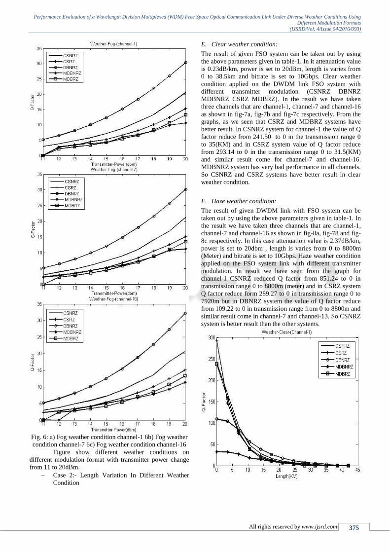
D. Fog weather condition:
The result of given DWDM link with FSO system can be
taken out by using the above parameters given in table-1.In
this case power is varies from 11 to 20dbm, attenuation
value is 84.90 dB/km, length is set to 345m (meter) and
bitrate is set to 10Gbps. Fog weather condition apply on the
DWDM link FSO channel with different transmitter
modulation. In the result we have taken three channels that
is channel-1, channel-7, channel-16 and these channel show
in the fig-6a, fig-6b and fig-6c respectively. From the graph
it is clear that DBNRZ system is better result than the other
systems. In the graph show that the value of Q factor is zero
at channel-1, channel-7 and channel-16 at transmitter power
is 11dBm, 11dBm and 12dBm respectively for MDBNRZ
system. So DBNRZ system is also better performance in fog
weather condition.
Fig. 3:a) Clear weather condition channel-1 3b) Clear
weather condition channel-73c) Clear weather condition
channel-16
Performance Evaluation of a Wavelength Division Multiplexed (WDM) Free Space Optical Communication Link Under Diverse Weather Conditions Using Different Modulation Formats
(IJSRD/Vol. 4/Issue 04/2016/093)
All rights reserved by www.ijsrd.com 374
Fig. 4: a) Haze weather condition channel-1 4b) Haze
weather condition channel-7 4c) Haze weather condition
channel-16
Fig. 5:a) Rain weather condition channel-1 5b) Rain
weather condition channel-7 5c) Rain weather condition
channel-16
Performance Evaluation of a Wavelength Division Multiplexed (WDM) Free Space Optical Communication Link Under Diverse Weather Conditions Using Different Modulation Formats
(IJSRD/Vol. 4/Issue 04/2016/093)
All rights reserved by www.ijsrd.com 375
Fig. 6: a) Fog weather condition channel-1 6b) Fog weather
condition channel-7 6c) Fog weather condition channel-16
Figure show different weather conditions on
different modulation format with transmitter power change
from 11 to 20dBm.
Case 2:- Length Variation In Different Weather
Condition
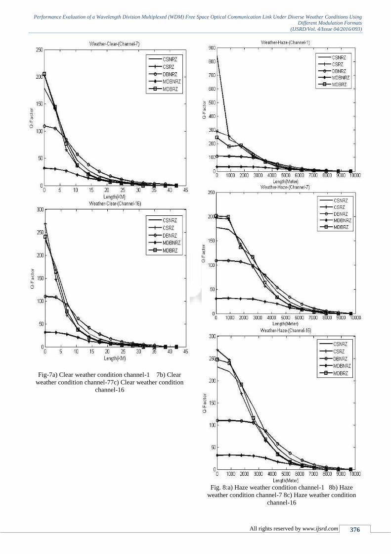
E. Clear weather condition:
The result of given FSO system can be taken out by using
the above parameters given in table-1. In it attenuation value
is 0.23dB/km, power is set to 20dBm, length is varies from
0 to 38.5km and bitrate is set to 10Gbps. Clear weather
condition applied on the DWDM link FSO system with
different transmitter modulation (CSNRZ DBNRZ
MDBNRZ CSRZ MDBRZ). In the result we have taken
three channels that are channel-1, channel-7 and channel-16
as shown in fig-7a, fig-7b and fig-7c respectively. From the
graphs, as we seen that CSRZ and MDBRZ systems have
better result. In CSNRZ system for channel-1 the value of Q
factor reduce from 241.50 to 0 in the transmission range 0
to 35(KM) and in CSRZ system value of Q factor reduce
from 293.14 to 0 in the transmission range 0 to 31.5(KM)
and similar result come for channel-7 and channel-16.
MDBNRZ system has very bad performance in all channels.
So CSNRZ and CSRZ systems have better result in clear
weather condition.
F. Haze weather condition:
The result of given DWDM link with FSO system can be
taken out by using the above parameters given in table-1. In
the result we have taken three channels that are channel-1,
channel-7 and channel-16 as shown in fig-8a, fig-78 and fig-
8c respectively. In this case attenuation value is 2.37dB/km,
power is set to 20dbm , length is varies from 0 to 8800m
(Meter) and bitrate is set to 10Gbps. Haze weather condition
applied on the FSO system link with different transmitter
modulation. In result we have seen from the graph for
channel-1 CSNRZ reduced Q factor from 851.24 to 0 in
transmission range 0 to 8800m (meter) and in CSRZ system
Q factor reduce form 289.27 to 0 in transmission range 0 to
7920m but in DBNRZ system the value of Q factor reduce
from 109.22 to 0 in transmission range from 0 to 8800m and
similar result come in channel-7 and channel-13. So CSNRZ
system is better result than the other systems.
Performance Evaluation of a Wavelength Division Multiplexed (WDM) Free Space Optical Communication Link Under Diverse Weather Conditions Using Different Modulation Formats
(IJSRD/Vol. 4/Issue 04/2016/093)
All rights reserved by www.ijsrd.com 376
Fig-7a) Clear weather condition channel-1 7b) Clear
weather condition channel-77c) Clear weather condition
channel-16
Fig. 8:a) Haze weather condition channel-1 8b) Haze
weather condition channel-7 8c) Haze weather condition
channel-16
Performance Evaluation of a Wavelength Division Multiplexed (WDM) Free Space Optical Communication Link Under Diverse Weather Conditions Using Different Modulation Formats
(IJSRD/Vol. 4/Issue 04/2016/093)
All rights reserved by www.ijsrd.com 377
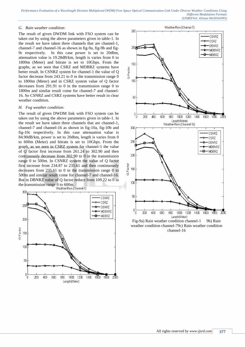
G. Rain weather condition:
The result of given DWDM link with FSO system can be
taken out by using the above parameters given in table-1. In
the result we have taken three channels that are channel-1,
channel-7 and channel-16 as shown in fig-9a, fig-9b and fig-
9c respectively. In this case power is set to 20dbm,
attenuation value is 19.28dB/km, length is varies from 0 to
1800m (Meter) and bitrate is set to 10Gbps. From the
graphs, as we seen that CSRZ and MDBRZ systems have
better result. In CSNRZ system for channel-1 the value of Q
factor decrease from 243.21 to 0 in the transmission range 0
to 1800m (Meter) and in CSRZ system value of Q factor
decreases from 291.91 to 0 in the transmission range 0 to
1800m and similar result come for channel-7 and channel-
16. So CSNRZ and CSRZ systems have better result in clear
weather condition.
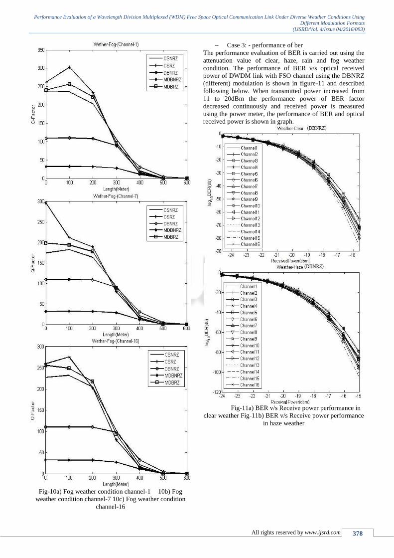
H. Fog weather condition:
The result of given DWDM link with FSO system can be
taken out by using the above parameters given in table-1. In
the result we have taken three channels that are channel-1,
channel-7 and channel-16 as shown in fig-10a, fig-10b and
fig-10c respectively. In this case attenuation value is
84.90dB/km, power is set to 20dbm, length is varies from 0
to 600m (Meter) and bitrate is set to 10Gbps. From the
graph, as we seen in CSRZ system for channel-1 the value
of Q factor first increase from 261.24 to 302.90 and then
continuously decrease from 302.90 to 0 in the transmission
range 0 to 500m. In CSNRZ system the value of Q factor
first increase from 234.87 to 235.61 and then continuously
decreases from 235.61 to 0 in the transmission range 0 to
500m and similar result come for channel-7 and channel-16.
But in DBNRZ value of Q factor reduce from 109.22 to 0 in
the transmission range 0 to 600m.
Fig-9a) Rain weather condition channel-1 9b) Rain
weather condition channel-79c) Rain weather condition
channel-16
Performance Evaluation of a Wavelength Division Multiplexed (WDM) Free Space Optical Communication Link Under Diverse Weather Conditions Using Different Modulation Formats
(IJSRD/Vol. 4/Issue 04/2016/093)
All rights reserved by www.ijsrd.com 378
Fig-10a) Fog weather condition channel-1 10b) Fog
weather condition channel-7 10c) Fog weather condition
channel-16
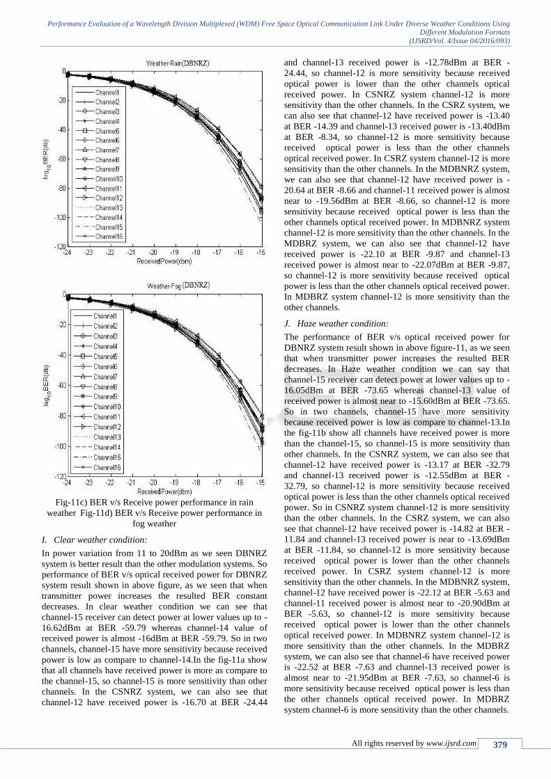
Case 3: - performance of ber
The performance evaluation of BER is carried out using the
attenuation value of clear, haze, rain and fog weather
condition. The performance of BER v/s optical received
power of DWDM link with FSO channel using the DBNRZ
(different) modulation is shown in figure-11 and described
following below. When transmitted power increased from
11 to 20dBm the performance power of BER factor
decreased continuously and received power is measured
using the power meter, the performance of BER and optical
received power is shown in graph.
Fig-11a) BER v/s Receive power performance in
clear weather Fig-11b) BER v/s Receive power performance
in haze weather
Performance Evaluation of a Wavelength Division Multiplexed (WDM) Free Space Optical Communication Link Under Diverse Weather Conditions Using Different Modulation Formats
(IJSRD/Vol. 4/Issue 04/2016/093)
All rights reserved by www.ijsrd.com 379
Fig-11c) BER v/s Receive power performance in rain
weather Fig-11d) BER v/s Receive power performance in
fog weather
I. Clear weather condition:
In power variation from 11 to 20dBm as we seen DBNRZ
system is better result than the other modulation systems. So
performance of BER v/s optical received power for DBNRZ
system result shown in above figure, as we seen that when
transmitter power increases the resulted BER constant
decreases. In clear weather condition we can see that
channel-15 receiver can detect power at lower values up to -
16.62dBm at BER -59.79 whereas channel-14 value of
received power is almost -16dBm at BER -59.79. So in two
channels, channel-15 have more sensitivity because received
power is low as compare to channel-14.In the fig-11a show
that all channels have received power is more as compare to
the channel-15, so channel-15 is more sensitivity than other
channels. In the CSNRZ system, we can also see that
channel-12 have received power is -16.70 at BER -24.44
and channel-13 received power is -12.78dBm at BER -
24.44, so channel-12 is more sensitivity because received
optical power is lower than the other channels optical
received power. In CSNRZ system channel-12 is more
sensitivity than the other channels. In the CSRZ system, we
can also see that channel-12 have received power is -13.40
at BER -14.39 and channel-13 received power is -13.40dBm
at BER -8.34, so channel-12 is more sensitivity because
received optical power is less than the other channels
optical received power. In CSRZ system channel-12 is more
sensitivity than the other channels. In the MDBNRZ system,
we can also see that channel-12 have received power is -
20.64 at BER -8.66 and channel-11 received power is almost
near to -19.56dBm at BER -8.66, so channel-12 is more
sensitivity because received optical power is less than the
other channels optical received power. In MDBNRZ system
channel-12 is more sensitivity than the other channels. In the
MDBRZ system, we can also see that channel-12 have
received power is -22.10 at BER -9.87 and channel-13
received power is almost near to -22.07dBm at BER -9.87,
so channel-12 is more sensitivity because received optical
power is less than the other channels optical received power.
In MDBRZ system channel-12 is more sensitivity than the
other channels.
J. Haze weather condition:
The performance of BER v/s optical received power for
DBNRZ system result shown in above figure-11, as we seen
that when transmitter power increases the resulted BER
decreases. In Haze weather condition we can say that
channel-15 receiver can detect power at lower values up to -
16.05dBm at BER -73.65 whereas channel-13 value of
received power is almost near to -15.60dBm at BER -73.65.
So in two channels, channel-15 have more sensitivity
because received power is low as compare to channel-13.In
the fig-11b show all channels have received power is more
than the channel-15, so channel-15 is more sensitivity than
other channels. In the CSNRZ system, we can also see that
channel-12 have received power is -13.17 at BER -32.79
and channel-13 received power is -12.55dBm at BER -
32.79, so channel-12 is more sensitivity because received
optical power is less than the other channels optical received
power. So in CSNRZ system channel-12 is more sensitivity
than the other channels. In the CSRZ system, we can also
see that channel-12 have received power is -14.82 at BER -
11.84 and channel-13 received power is near to -13.69dBm
at BER -11.84, so channel-12 is more sensitivity because
received optical power is lower than the other channels
received power. In CSRZ system channel-12 is more
sensitivity than the other channels. In the MDBNRZ system,
channel-12 have received power is -22.12 at BER -5.63 and
channel-11 received power is almost near to -20.90dBm at
BER -5.63, so channel-12 is more sensitivity because
received optical power is lower than the other channels
optical received power. In MDBNRZ system channel-12 is
more sensitivity than the other channels. In the MDBRZ
system, we can also see that channel-6 have received power
is -22.52 at BER -7.63 and channel-13 received power is
almost near to -21.95dBm at BER -7.63, so channel-6 is
more sensitivity because received optical power is less than
the other channels optical received power. In MDBRZ
system channel-6 is more sensitivity than the other channels.
Performance Evaluation of a Wavelength Division Multiplexed (WDM) Free Space Optical Communication Link Under Diverse Weather Conditions Using Different Modulation Formats
(IJSRD/Vol. 4/Issue 04/2016/093)
All rights reserved by www.ijsrd.com 380
Rain weather condition: In Rain weather condition we can
say that channel-15 receiver can detect power at lower
values up to -17.04dBm at BER -51.12 whereas channel-2
value of received power is almost near to -16.60dBm at
BER -51.12. So in two channels, channel-15 have more
sensitivity because received power is less as compare to
channel-2.In the fig-11c show all channels have received
power is higher than the channel-15, so channel-15 is more
sensitivity than other channels. In the CSNRZ system, we
can also see that channel-15 have received power is -14.16
at BER -20.76 and channel-13 received power is -13.20dBm
at BER -20.76, so channel-15 is more sensitivity because
received optical power is low than the other channels
optical received power. So in CSNRZ system channel-15 is
high sensitivity than the other channels. . In the CSRZ
system, we can also see that channel-12 have received
power is -14.82 at BER -12.16 and channel-13 received
power is -13.70dBm at BER -12.16, so channel-12 is more
sensitivity because received optical power is less than the
other channels optical received power. In CSRZ system
channel-12 is high sensitivity than the other channels. In the
MDBNRZ system, channel-12 have received power is -
21.08at BER -6.94 and channel-13 received power is almost
near to -20.65dBm at BER -6.94, so channel-12 is more
sensitivity because received optical power is lower than the
other channels optical received power. In MDBNRZ system
channel-12 is more sensitivity than the other channels. In the
MDBRZ system, we can also see that channel-12 have
received power is -22.52 at BER -7.88 and channel-5
received power is almost near to -21.85dBm at BER -7.88,
so channel-12 is more sensitivity because received power is
less than the other channels optical received power. In
MDBRZ system channel-12 is more sensitivity than the
other channels.
K. Fog weather condition:
In Fog weather condition we can say that channel-15
receiver can detect power at lower values up to -16.99dBm
at BER -51.56 whereas channel-2 value of received power is
almost near to -16.45dBm at BER -51.56. So in two
channels, channel-15 has more sensitivity because received
power is less as compare to channel-13.In the fig-11d show
all channels have received power is higher than the channel-
15, so channel-15 is more sensitivity than other channels. In
the CSNRZ system, that channel-12 has received power is -
14.17 at BER -21.36 and channel-13 received power is -
13.25dBm at BER -21.36, so channel-12 is high sensitivity
because received power is less than the other channels
optical received power. So in CSNRZ system channel-12 is
more sensitivity than the other channels. In the CSRZ
system, channel-12 have received power is -14.75 at BER -
12.12 and channel-11 received power is almost near to -
13.64dBm at BER -12.12, so channel-12 is more sensitivity
because received optical power is less than the other
channels optical received power. In CSRZ system channel-
12 is more sensitivity than the other channels. In the
MDBNRZ system, channel-12 has received power is -21.05
at BER -6.91 and channel-11 received power is almost near
to -20.78dBm at BER -6.91, so channel-12 is more
sensitivity because received optical power is lower than the
other channels optical received power. In MDBNRZ system
channel-12 is more sensitivity than the other channels. In
MDBRZ system, we can also see that channel-12 has
received power is -22.47 at BER -8.31 and channel-13
received power is almost near to -21.23dBm at BER -8.31
so channel-12 is high sensitivity because received optical
power is less than the other channels optical received power.
In MDBRZ system channel-12 is more sensitivity than the
other channels.
VII. CONCLUSIONS
We have simulated 16 channel 10Gbps DWDM link with
FSO channel under different weather condition at 1nm
channel spacing over a transmission distance using different
modulation (CSNRZ CSRZ DBNRZ MDBNRZ and
MDBRZ) format with changing power and distance. From
the results it is clear that transmission range decrease when
power is varied from 11 to 20dBm under different weather
condition changing from clear to fog.
In first case when power is varied for different
weather conditions (clear, haze, rain and fog) it is observed
that DBNRZ system gives better result than the other
systems in all the cases because in 16 channels result is
similar. In the second case when length is varied in different
weather conditions then it is observed that CSNRZ gives
better results in almost all the cases with CSRZ in certain
cases because in 16 channels result is similar. Also, the
performance of BER from all received signal in DBNRZ
under clear weather condition, channel-15 received signal
can detect at lower received power value up to -16.62dBm at
BER -59.79 whereas channel-14 value of received signal
detect with received power almost -16dBm at BER -59.79,
so channel-15 has more sensitivity. In the CSNRZ system
channel-12 has lower optical received power is -16.70 at
BER -24.44 and in CSRZ system signal is detect lower
received power is -13.40 at BER -14.39 and in MDBNRZ
system channel-12 signal is detect with received power is -
20.64dBm at BER -8.66. In MDBRZ system channel-12
detects with received power is lower-22.10 at BER -9.87. So
channel-12 is more sensitivity than the other channels
because have received power is lowest.
The performance of BER from all received signal
in DBNRZ under haze weather condition, channel-15
received signal can detect at lower received power value up
to -16.05dBm at BER -73.65, so channel-15 have more
sensitivity. In the CSNRZ and CSRZ and MDBNRZ system
channel-12 signal detect have lower received power is -
13.17 at BER -32.79 and -14.82 at BER -11.84 and -22.12 at
BER -5.63 respectively, so in CSNRZ, CSRZ and
MDBNRZ systems channel-12 is more sensitivity than the
other channels but in MDBRZ system channel-6 is more
sensitivity than the other channels because channel-6 has
received power is -22.52 at BER -7.63.
The performance of BER from all received signal
in DBNRZ and CSNRZ under haze weather condition,
channel-15 received signal can detect at lower received
power value up to -17.04dBm at BER -51.12, so channel-15
have more sensitivity. In CSRZ and MDBNRZ system
channel-12 is high sensitivity but in MDBRZ system
channel-6 is more sensitivity than the other channels.
performance of BER from all received signal in
DBNRZ and CSNRZ under haze weather condition,
channel-15 received signal can detect at lower received
Performance Evaluation of a Wavelength Division Multiplexed (WDM) Free Space Optical Communication Link Under Diverse Weather Conditions Using Different Modulation Formats
(IJSRD/Vol. 4/Issue 04/2016/093)
All rights reserved by www.ijsrd.com 381
power values up to -16.99dBm at BER -51.56, so channel-
15 have more sensitivity. In the CSNRZ, CSRZ, MDBNRZ
and MDBRZ channel-12 is more sensitivity than the other
channels.
From results it is concluded that in the power
variation DBNRZ modulation system is better and in length
variation CSNRZ modulation format is better than the other
modulation formats for different weather conditions.
REFERENCE
[1] Kolka, Z., Wilfert, O., Kvicala, R., Fiser, O. Complex
Model Of Terrestial FSO Links. Proceedings Of
Spie,2007, VOL.6709,P.67091J.
[2] David, F. Scintillation Loss In Free-Space Optic Im/Dd
Systems. In Lase 2004, Vol.5338. San Jose(U.sa),2004.
[3] Shivinder Devra, Gurmeet Kaur, “Different
Compensation Techniques to Compensate Chromatic
Dispersion in Fiber Optics”, International Journal of
Engineering and Information Technology, vol. 3, no. 1,
pp. 1-4, 2011 (ISSN 0975-5292 (Print), ISSN 0976-
0253.
[4] Karamdeep Singh, Gurmeet Kaur, Maninder Lal Singh,
“A single As2Se3 chalcogenide Highly Non-Linear
Fiber (HNLF) based simultaneous all-optical half-adder
and half-subtracter”, locate, vol. 24, pp. 56-63, April
2015.
[5] Shivinder Devra, Gurmeet Kaur, “Dispersion
Compensation using Raised Cosine Filter in optical
fibers”, International Journal on Information and
Electronics Engineering, vol. 1, no. 1, pp. 47-51, July
2011 (ISSN: 2010-3719)
[6] Shivinder Devra, Gurmeet Kaur, “Dispersion
Compensation using All Pass Filters in Optical Fibers”,
Proc. 2011 International Conference on Information and
Electronics Engineering, IACSIT press, vol. 6, no. 5,
pp. 218-222, 2011.
[7] Ross Saunders, Coherent DWDM technology for high
speed optical communications, Optical Fiber
Technology, Opnext Subsytems Inc., 151 Albright
Way, Los Gatos, CA 95032, USA , vol-1 ,(2011), pp.
445–451 .
[8] Simranjit Singh , Raman , Performance investigation on
DWDM optical ring network to increasethe capacity
with acceptable performance, International Journal for
Light and Electron optic, vol-125, 2014, pp. 5750-5752.
[9] R. Randhawaa, J.S. Sohalb, R.S. Kaler, Protection and
restoration of ring in packetswitched wavelength
division multiplexed transport networks, Optik 121
(2010)1013–1018.
[10] S. Singh, R.S. Kaler, Novel optical flat gain hybrid
amplifier for dense wavelengthdivision multiplexed
system, IEEE Photon. Technol. Lett. 26 (2) (2014) 173–
176.
[11] ITU-T Rec. G.694.1, Spectral Grids for WDM
Applications: DWDM Frequency Grid, 06/2002.
[12] Reena Antil, Pinki, Sonal Beniwal, an overview of
DWDM technology and network, International Journal
of scientific and technology research, vol-1, issue-
11,December 2012.
[13] T. Sabapathia , S. Sundaravadivelu , Analysis of
bottlenecks in DWDM fiber optic communication
system, International Journal for Light and Electron
optic, vol-122 , 2011 , pp.1453-1457
[14] www.flyinoptronics.com
[15] www.fowiki.com
[16] Ajay K. Sharma, S.K. Wadhwa, T.S. Kamal,“
Robustness of NRZ , RZ, CSRZ modulation on fiber
Nonlinearities and amplifier noise at 40Gbps for Long
Haul Link”, Optik International Journal for Light and
Electron optics, vol. 120, pp. 614-618, 2009.
[17] Farukh Nadeem, Vaclav Kvicera, Muhammad Saleem
Awan, Erich Leitgeb, Sajid Sheikh Muhammad, Gorazd
Kandus, “Weather Effects on Hybrid FSO/RF
Communication Link,” IEEE journal on selected areas
in communications, vol. 27, no. 9, December 2009.
[18] E. Ciaramella, Y. Arimoto, G. Contestabile, M. Presi,
A. D’Errico, V. Guarino, and M. Matsumoto, “1.28
Terabit/s (32x40 Gbit/s) WDM Transmission System
for Free Space Optical Communications,” IEEE journal
on selected areas in communications, vol. 27, no. 9,
december 2009.
[19] Jagjit Singh Malhotra, Manoj Kumar, Ajay K. Sharma,
Alok Kumar, “Performance evaluation of 16 channel
DWDM radio-over-fiber link”, International Journal for
Light and Electron optics, vol. 124, pp. 4120-4122,
2013.
[20] T. Sabapathi, S. Sundaravadivelu, “Analysis of
bottlenecks in DWDM fiber optic communication
system,” Optik vol. 122, pp. 1453– 1457, 2011.
[21] Ross Saunders, “Coherent DWDM technology for high
speed optical communications,” Optical Fiber
Technology vol. 17, pp. 445–451, 2011.
[22] Anu Sheetal, Ajay K.Sharma, R.S. Kaler, “Simulation
of high capacity 40 Gb/s long haul DWDM system
using different modulation formats and dispersion
compensation schemes in the presence of Kerr’s effect”,
International Journal for Light and Electron optics, vol.
121, pp.739-749, 2010
[23] Ashish Kumar, Aakash Dhiman, Devender Kumar,
Naresh Kumar, “ Free Space Optical Commmunication
System under Different Weather Conditions”,IOSR
Journal of Engineering, e-ISSN: 2250-3021, p-
ISSN:2278-8719, VOL. 3, ISSUE 12, V2, PP. 52-588,
2013.
[24] Michael Cheffena, “The effect of rain attenuation on the
performance of BFWA around Kjeller, Norway”, IEEE
photonic Journals, vol. 2, no. 3, pp. 121-128, December
2008.
[25] D. K. Borah and D. G. Voelz, “Pointing Error Effects
on Free- Space Optical Communication Links in The
Presence of Atmospheric Turbulence”, Jornals of
Lightwave Technolgy, vol. 27, no. 18, pp. 3965-3973,
September. 2009.
[26] Jun He , Robert A. Norwood , Maïté Brandt-Pearce ,
Ivan B. Djordjevic , Milorad Cvijetic ,Suresh
Subramaniam , Roland Himmelhuber , Carolyn
Reynolds , Pierre Blanche ,Brittany Lynn , Nasser
Peyghambarian , “A survey on recent advances in
optical communications”, Computers and Electrical
Engineering, vol.40, pp.216-240, 2014
[27] Salwinder singh, Karamdeep singh and Shivinder
devra,“Simulative Performance Evaluation of a Free
Performance Evaluation of a Wavelength Division Multiplexed (WDM) Free Space Optical Communication Link Under Diverse Weather Conditions Using Different Modulation Formats
(IJSRD/Vol. 4/Issue 04/2016/093)
All rights reserved by www.ijsrd.com 382
Space Optical Communication Link Operating at 1550
nm using Different Modulation Formats” International
Journal of Computer Applications Technology and
Research Volume 5, Issue 6, 320 - 329, 2016.
[28] Karamdeep Singh and Gurmeet Kaur, “Interferometric
Architectures based All-Optical Logic Design Methods
and their Implementations” Optics and Laser
Technology, Vol. 65, June 2015, pp. 122-132
[29] Salwinder singh, Karamdeep singh and Shivinder
devra,“Performance Investigation Of A Free Space
Optical Communication Link Operating At 1550 Nm
Under Diverse Weather Conditions By Employing
Different Modulation Formats” International Journal Of
Engineering Sciences & Research Technology Volume
5, Issue 5, 466- 478, May 2016