
PERFORMANCE ENHANCEMENT IN PROTON ... ENHANCEMENT IN PROTON EXCHANGE MEMBRANE FUEL CELL –...
57
PERFORMANCE ENHANCEMENT IN PROTON EXCHANGE MEMBRANE FUEL CELL – NUMERICAL MODELING AND OPTIMISATION Student: S.O. OBAYOPO Supervisor: Prof. T. Bello-Ochende Co-supervisor: Prof. J.P. Meyer 1
Transcript of PERFORMANCE ENHANCEMENT IN PROTON ... ENHANCEMENT IN PROTON EXCHANGE MEMBRANE FUEL CELL –...
PERFORMANCE ENHANCEMENT IN PROTON EXCHANGE MEMBRANE FUEL
CELL – NUMERICAL MODELING AND OPTIMISATION
Student: S.O. OBAYOPO
Supervisor: Prof. T. Bello-Ochende
Co-supervisor: Prof. J.P. Meyer
1
Presentation overview
Introduction (Fuel cell technology & challenges)
Objective of the research
Research Methodology
Trends and results
Conclusion, recommendations & remarks
2
World Energy concerns:
Increasing world population and production activity.
Pollution increase through fossil fuels.
Emergence of renewable energy sources (solar, Fuel cell, wind, etc.).
Fuel cell potentials (PEMFC, SOFC, AFC, DMFC):
Low pollution potentials
Highly efficient power devices
Portability & remote application
South Africa platinum exploration (80% of world production)
3
A case for PEM fuel cell:
High power density
High efficiency
Fast start-up (low temperature of operation)
Remote applications
Dynamic response capability in automobile application
4
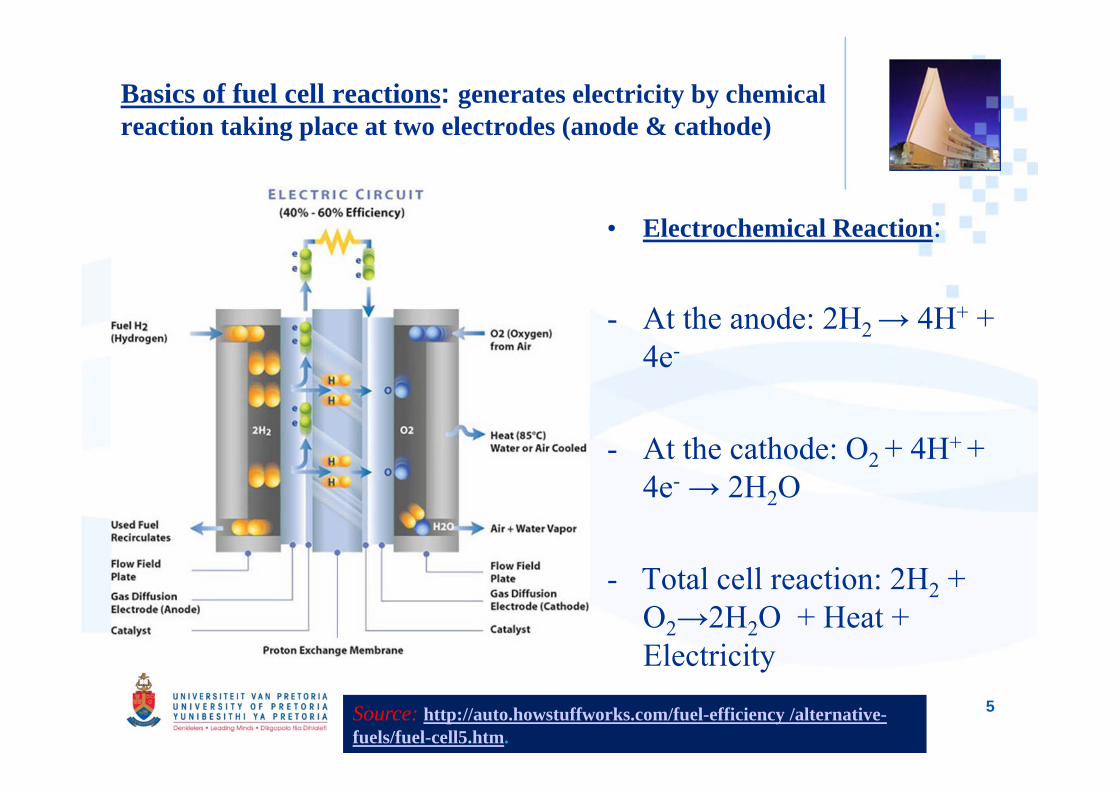
Basics of fuel cell reactions: generates electricity by chemical reaction taking place at two electrodes (anode & cathode)
• Electrochemical Reaction:
- At the anode: 2H2 → 4H+ + 4e-
- At the cathode: O2 + 4H+ + 4e- → 2H2O
- Total cell reaction: 2H2 + O2→2H2O + Heat + Electricity
Source: http://auto.howstuffworks.com/fuel-efficiency /alternative-fuels/fuel-cell5.htm.
5
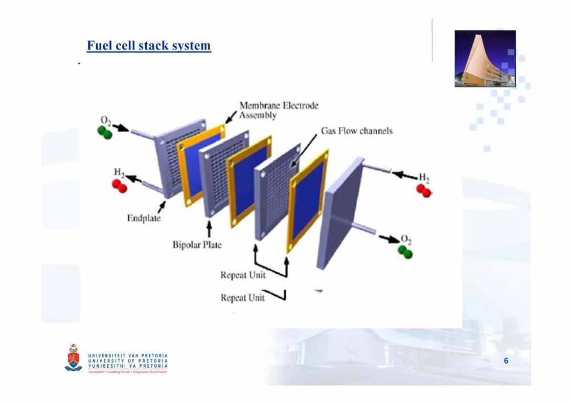
Fuel cell stack system
Fuel cell stack structure:
6
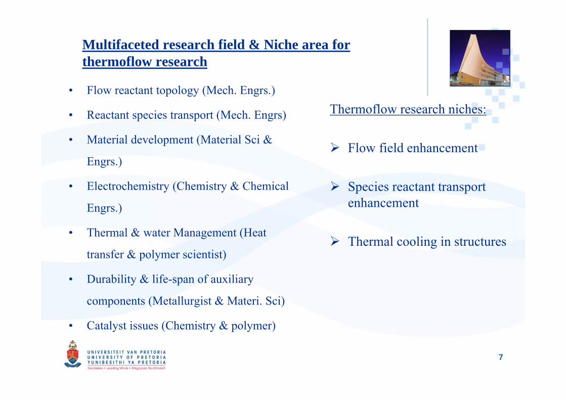
Multifaceted research field & Niche area for thermoflow research
• Flow reactant topology (Mech. Engrs.)
• Reactant species transport (Mech. Engrs)
• Material development (Material Sci &
Engrs.)
• Electrochemistry (Chemistry & Chemical
Engrs.)
• Thermal & water Management (Heat
transfer & polymer scientist)
• Durability & life-span of auxiliary
components (Metallurgist & Materi. Sci)
• Catalyst issues (Chemistry & polymer)
Thermoflow research niches:
Flow field enhancement
Species reactant transport enhancement
Thermal cooling in structures
7
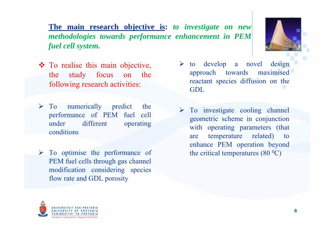
The main research objective is: to investigate on newmethodologies towards performance enhancement in PEMfuel cell system.
To realise this main objective,the study focus on thefollowing research activities:
To numerically predict theperformance of PEM fuel cellunder different operatingconditions
To optimise the performance ofPEM fuel cells through gas channelmodification considering speciesflow rate and GDL porosity
to develop a novel designapproach towards maximisedreactant species diffusion on theGDL
To investigate cooling channelgeometric scheme in conjunctionwith operating parameters (thatare temperature related) toenhance PEM operation beyondthe critical temperatures (80 0C)
8
Numerical Modeling & optimisation
• CFD code – ANSYS FLUENT (Fuel cell add-on)
• Dynamic-Q algorithm (Prof. J.A. Snyman)
• Basic assumptions:
Cell operates under steady-state conditions,
Flow in the cell is considered to be laminar,
Reactant and products are assumed to be ideal gas mixtures,
Electrode is assumed to be an isotropic and homogeneous porous
medium.
9
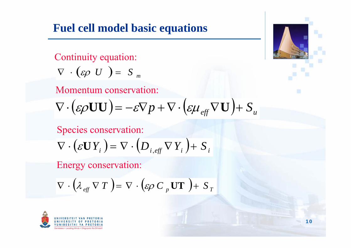
Fuel cell model basic equations
Momentum conservation:
Continuity equation: mSU
ueff Sp UUU
Species conservation:
iieffii SYDY ,UEnergy conservation:
Tpeff SCT UT
10
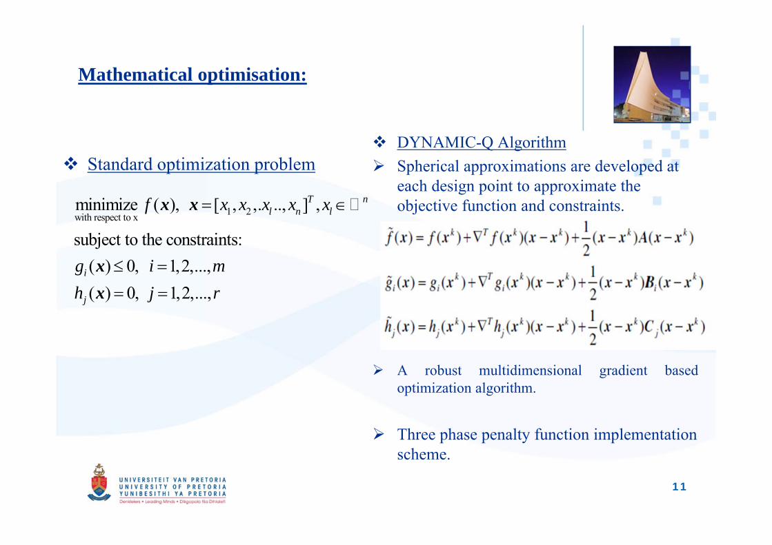
Mathematical optimisation:
Standard optimization problem DYNAMIC-Q Algorithm Spherical approximations are developed at
each design point to approximate the objective function and constraints.
A robust multidimensional gradient basedoptimization algorithm.
Three phase penalty function implementation scheme.
1 2with respect to xminimize ( ), [ , ,. .., ] ,
subject to the constraints:( ) 0, 1,2,...,( ) 0, 1,2,...,
T nl n l
i
j
f x x x x x
g i mh j r
x x
xx
11
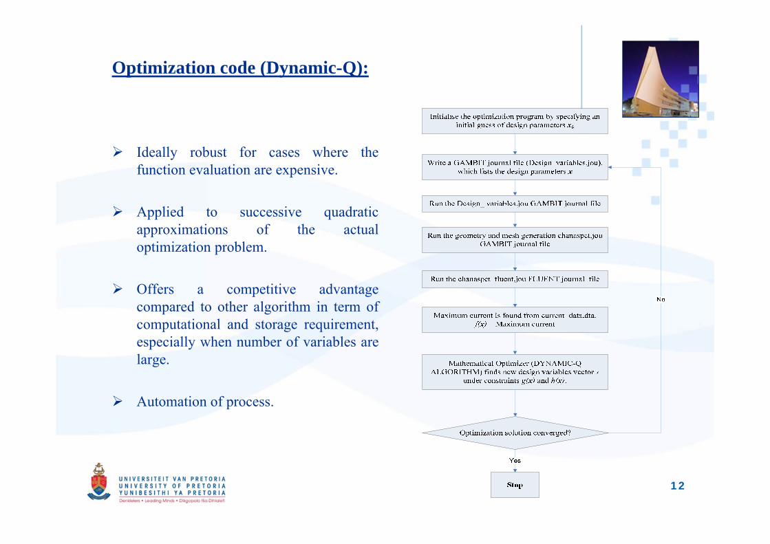
Optimization code (Dynamic-Q):
Ideally robust for cases where thefunction evaluation are expensive.
Applied to successive quadraticapproximations of the actualoptimization problem.
Offers a competitive advantagecompared to other algorithm in term ofcomputational and storage requirement,especially when number of variables arelarge.
Automation of process.
12
13
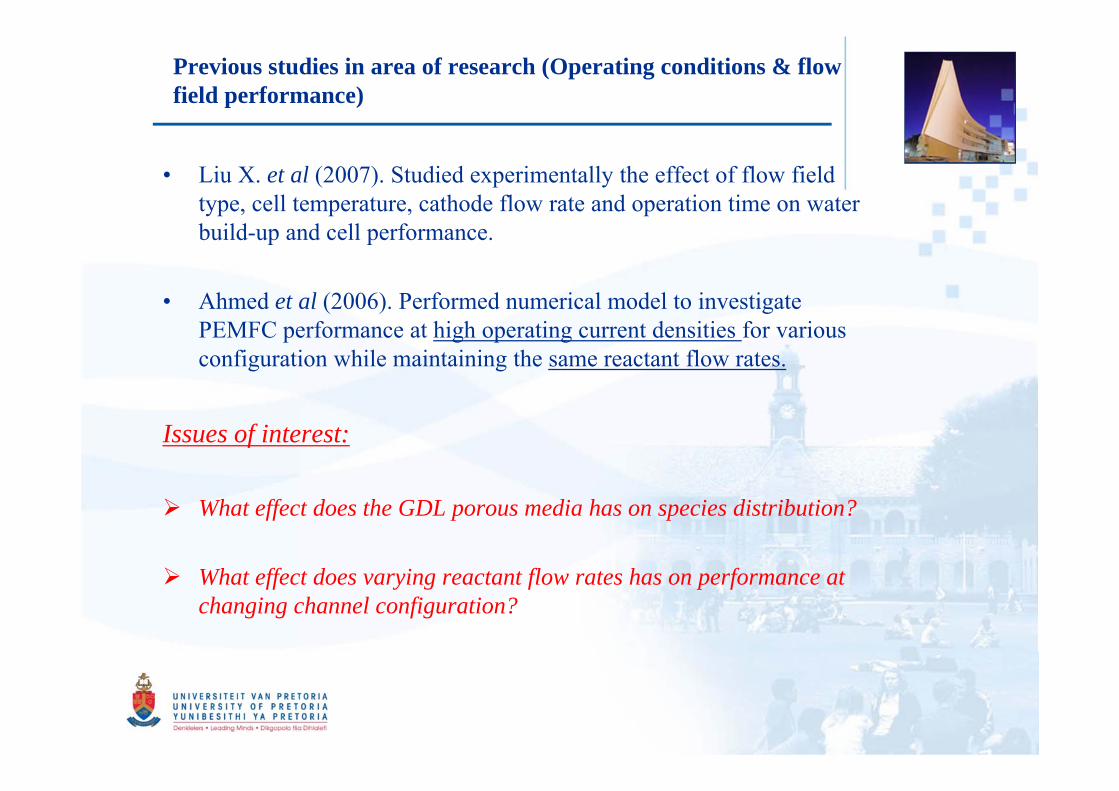
Previous studies in area of research (Operating conditions & flow field performance)
• Liu X. et al (2007). Studied experimentally the effect of flow field type, cell temperature, cathode flow rate and operation time on water build-up and cell performance.
• Ahmed et al (2006). Performed numerical model to investigate PEMFC performance at high operating current densities for various configuration while maintaining the same reactant flow rates.
Issues of interest:
What effect does the GDL porous media has on species distribution?
What effect does varying reactant flow rates has on performance at changing channel configuration?
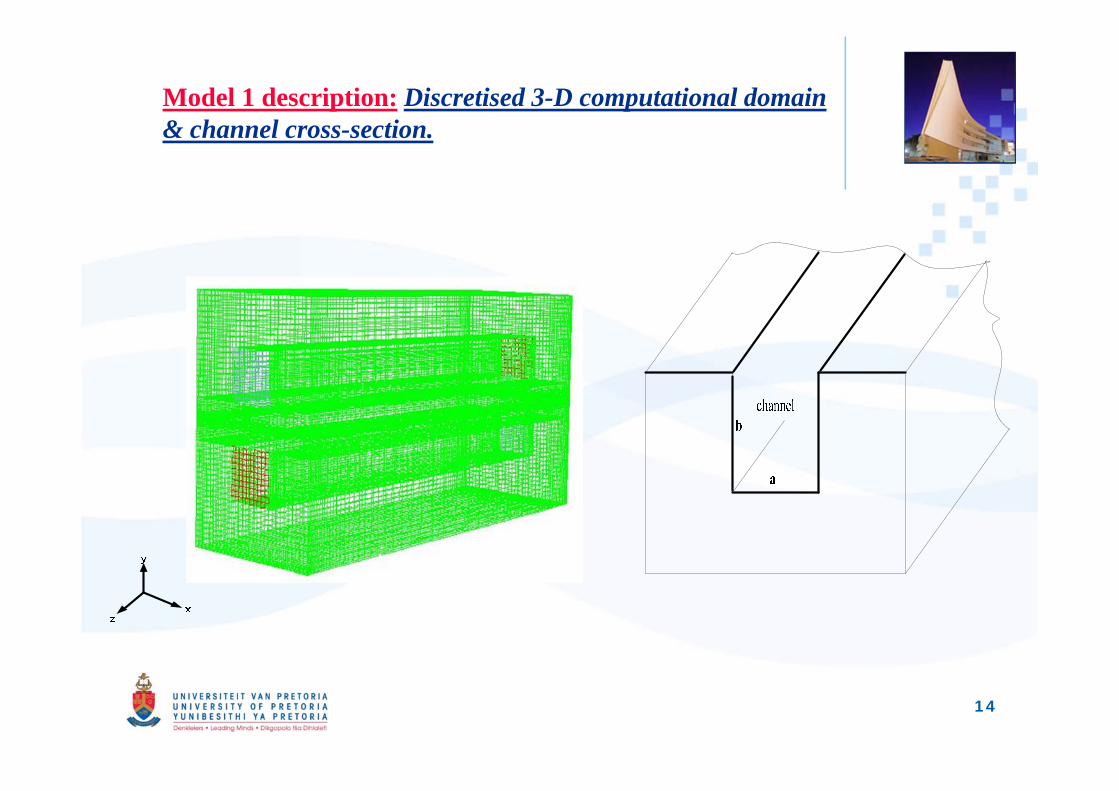
Model 1 description: Discretised 3-D computational domain & channel cross-section.
14
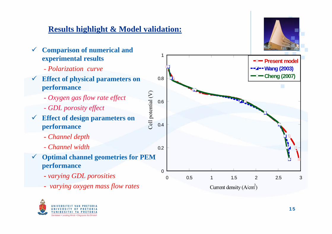
Results highlight & Model validation:
Comparison of numerical and experimental results - Polarization curve
Effect of physical parameters on performance- Oxygen gas flow rate effect- GDL porosity effect
Effect of design parameters on performance- Channel depth - Channel width
Optimal channel geometries for PEM performance- varying GDL porosities- varying oxygen mass flow rates
0
0.2
0.4
0.6
0.8
1
0 0.5 1 1.5 2 2.5 3
Present modelWang (2003)Cheng (2007)
Cell
pote
ntia
l (V
)
Current density (A/cm2)
15
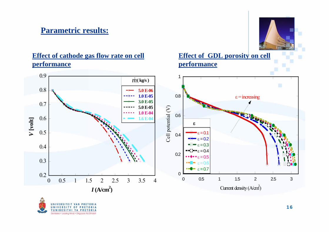
Parametric results:
Effect of cathode gas flow rate on cell performance
Effect of GDL porosity on cell performance
0.2
0.3
0.4
0.5
0.6
0.7
0.8
0.9
0 0.5 1 1.5 2 2.5 3 3.5 4
5.0 E-06 1.0 E-05 3.0 E-05 5.0 E-05 1.0 E-04 1.6 E-04
V [v
olt]
I (A/cm2)
( kg/s )
m
0
0.2
0.4
0.6
0.8
1
0 0.5 1 1.5 2 2.5 3
= 0.1 = 0.2 = 0.3 = 0.4 = 0.5 = 0.6 = 0.7
Cel
l pot
entia
l (V
)
Current density (A/cm2)
= increasing
16
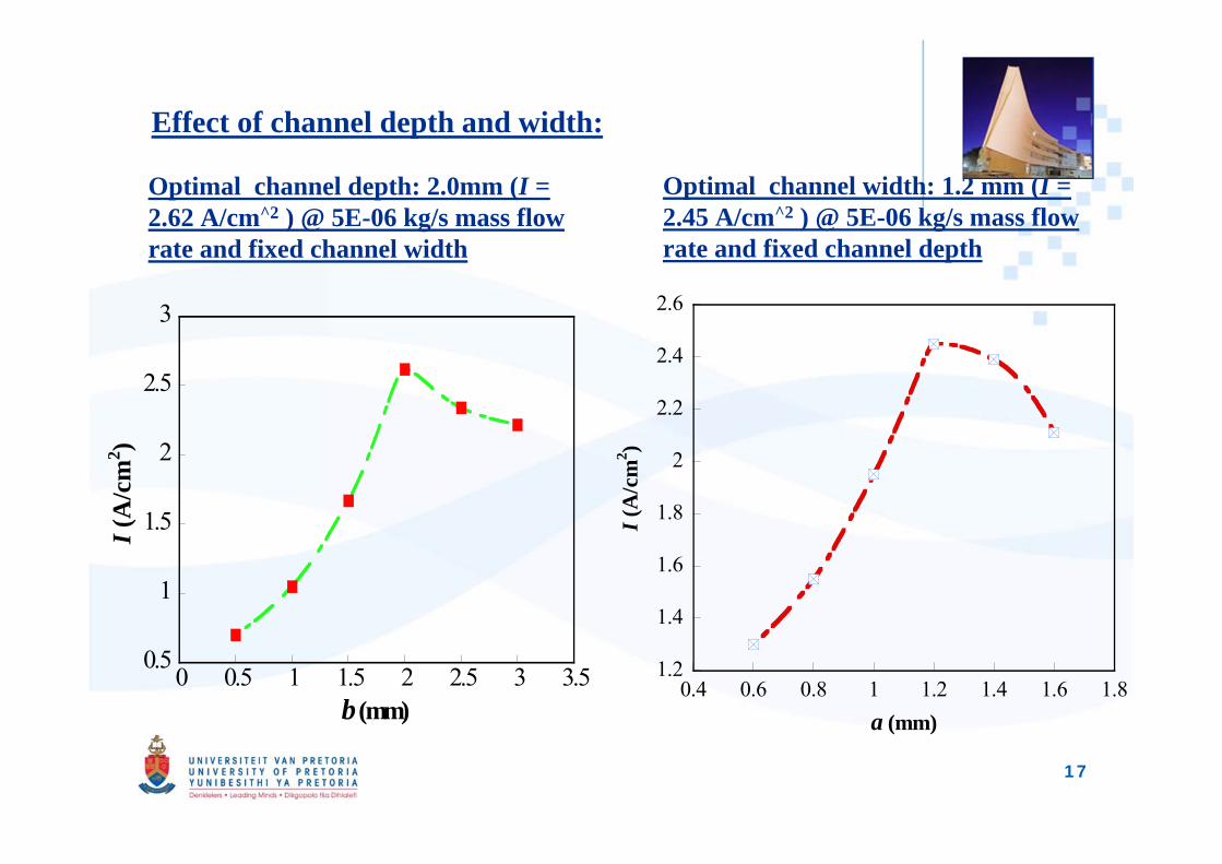
Effect of channel depth and width:
Optimal channel depth: 2.0mm (I = 2.62 A/cm^2 ) @ 5E-06 kg/s mass flow rate and fixed channel width
Optimal channel width: 1.2 mm (I = 2.45 A/cm^2 ) @ 5E-06 kg/s mass flow rate and fixed channel depth
0.5
1
1.5
2
2.5
3
0 0.5 1 1.5 2 2.5 3 3.5
I (A
/cm
2 )
b (mm)
1.2
1.4
1.6
1.8
2
2.2
2.4
2.6
0.4 0.6 0.8 1 1.2 1.4 1.6 1.8
I (A
/cm
2 )
a (mm)
17
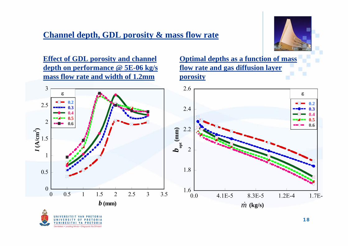
Channel depth, GDL porosity & mass flow rate
Effect of GDL porosity and channel depth on performance @ 5E-06 kg/s mass flow rate and width of 1.2mm
Optimal depths as a function of mass flow rate and gas diffusion layer porosity
0
0.5
1
1.5
2
2.5
3
0 0.5 1 1.5 2 2.5 3 3.5
0.2 0.3 0.4 0.5 0.6
I (A
/cm
2 )
b (mm)
1.6
1.8
2
2.2
2.4
2.6
0.2 0.3 0.4 0.5 0.6
0.0 4.1E-5 8.3E-5 1.2E-4 1.7E-4
b opt (m
m)
(kg/s)
m
18
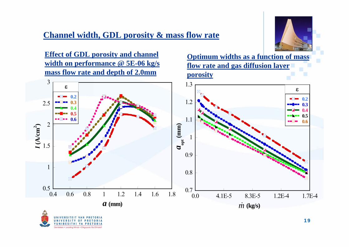
Channel width, GDL porosity & mass flow rate
Effect of GDL porosity and channel width on performance @ 5E-06 kg/s mass flow rate and depth of 2.0mm
Optimum widths as a function of mass flow rate and gas diffusion layer porosity
0.5
1
1.5
2
2.5
3
0.4 0.6 0.8 1 1.2 1.4 1.6 1.8
0.2 0.3 0.4 0.5 0.6
I (A
/cm
2 )
a (mm)
0.7
0.8
0.9
1
1.1
1.2
1.3
0.0 4.1E-5 8.3E-5 1.2E-4 1.7E-4
0.2 0.3 0.4 0.5 0.6
a opt (m
m)
(kg/s)
m
19
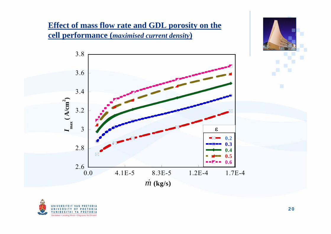
Effect of mass flow rate and GDL porosity on the cell performance (maximised current density)
2.6
2.8
3
3.2
3.4
3.6
3.8
0.0 4.1E-5 8.3E-5 1.2E-4 1.7E-4
0.2 0.3 0.4 0.5 0.6
I max
( A
/cm
2 )
(kg/s)
m
20
21
Research objective 2:Previous studies in area of research (Species diffusion optimisation in flow field)
• Soong. et al. (2005). Developed a flow channel configuration by insertingbaffles in the conventional flow field channels. Performance was enhancedthough with penalty of higher pressure loss.
• Wang et al. (2007). Studied the use of baffles in a serpentine flow field toimprove performance in PEM fuel cell. The baffles helps gas diffusionleading to enhanced current density though at higher pressure differencebetween adjacent flow channels.
Issues of interest: Investigate on pin fins geometry on reactant gas distribution in PEM
fuel cell Investigate of a trade-off between the performance enhancement &
pumping power requirement due to pressure drop.
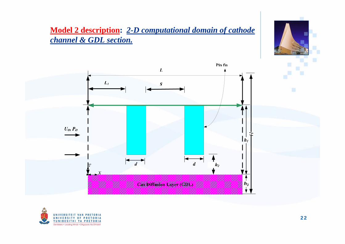
Model 2 description: 2-D computational domain of cathode channel & GDL section.
22
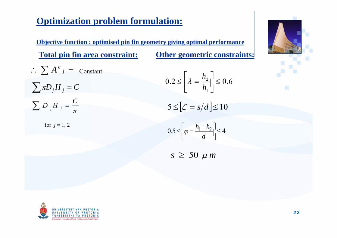
Optimization problem formulation:
Objective function : optimised pin fin geometry giving optimal performance
Total pin fin area constraint: Other geometric constraints:
Constant
for j = 1, 2
jcA
CHD jj
CHD jj
6.02.01
2
hh
105 ds
45.0 21
d
hh
ms 50
23
Results highlights:
Results of flow field:
Results of pin fin geometry:
Optimization results:
Performance evaluation:
24
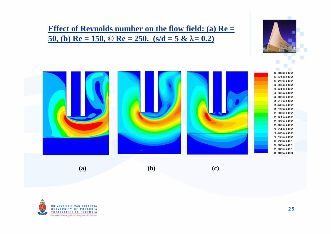
Effect of Reynolds number on the flow field: (a) Re = 50, (b) Re = 150, © Re = 250. (s/d = 5 & = 0.2)
(a) (b) (c)
25
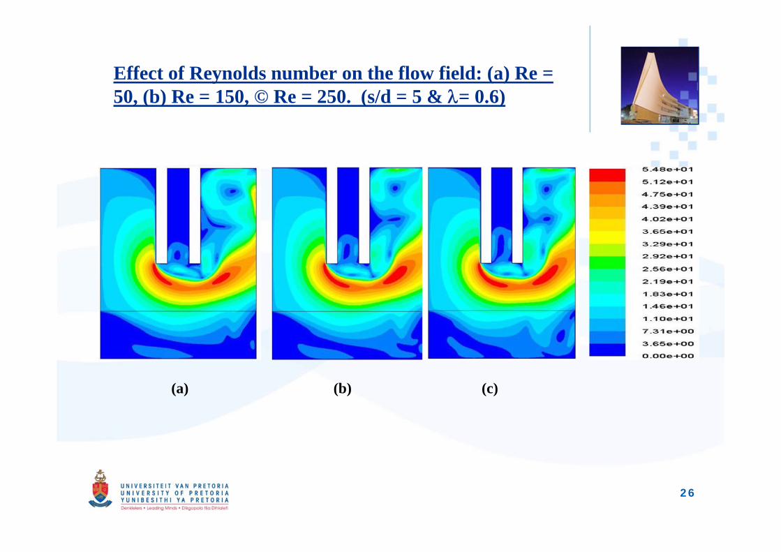
Effect of Reynolds number on the flow field: (a) Re = 50, (b) Re = 150, © Re = 250. (s/d = 5 & = 0.6)
(a) (b) (c)
26
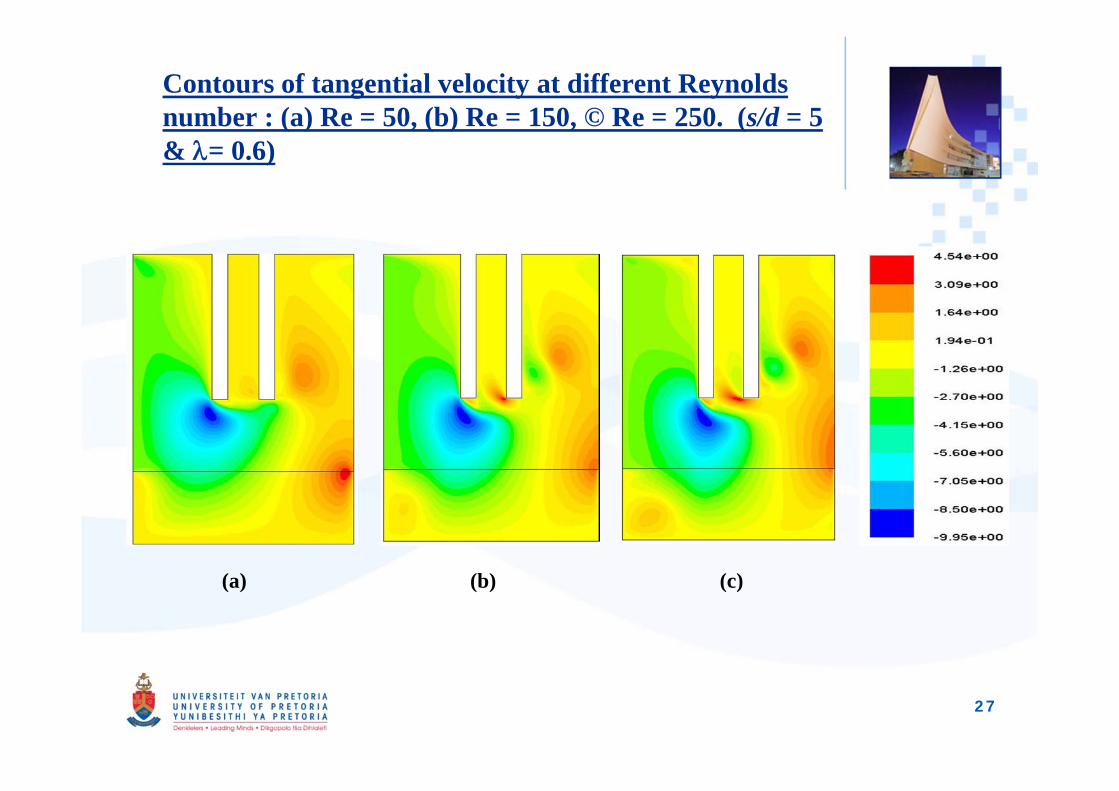
Contours of tangential velocity at different Reynolds number : (a) Re = 50, (b) Re = 150, © Re = 250. (s/d = 5 & = 0.6)
(a) (b) (c)
27
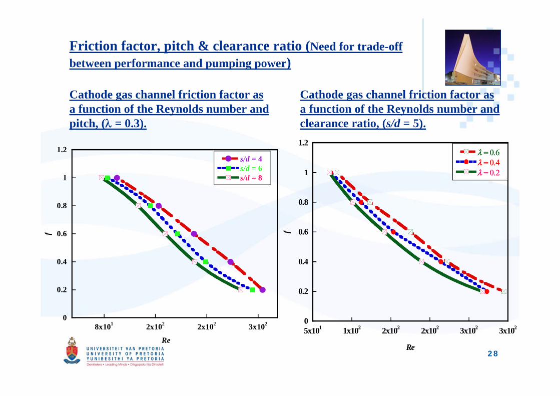
Friction factor, pitch & clearance ratio (Need for trade-off between performance and pumping power)
Cathode gas channel friction factor as a function of the Reynolds number and pitch, ( = 0.3).
Cathode gas channel friction factor as a function of the Reynolds number and clearance ratio, (s/d = 5).
0
0.2
0.4
0.6
0.8
1
1.2
8x101 2x10² 2x10² 3x10²
s/d = 4s/d = 6s/d = 8
f
Re
0
0.2
0.4
0.6
0.8
1
1.2
5x101 1x10² 2x10² 2x10² 3x10² 3x10²
f
Re28
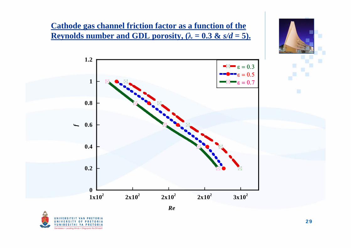
Cathode gas channel friction factor as a function of the Reynolds number and GDL porosity, ( = 0.3 & s/d = 5).
0
0.2
0.4
0.6
0.8
1
1.2
1x10² 2x10² 2x10² 2x10² 3x10²
f
Re
29
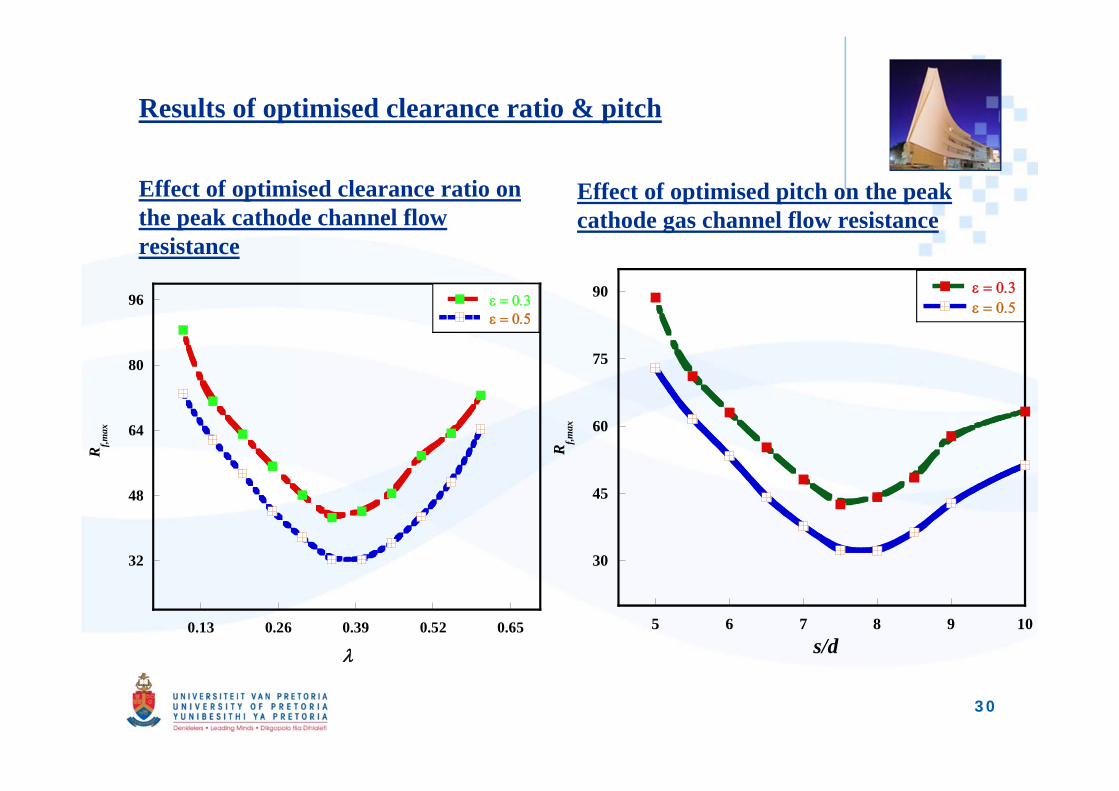
Results of optimised clearance ratio & pitch
Effect of optimised clearance ratio on the peak cathode channel flow resistance
Effect of optimised pitch on the peak cathode gas channel flow resistance
32
48
64
80
96
0.13 0.26 0.39 0.52 0.65
Rf,m
ax
30
45
60
75
90
5 6 7 8 9 10
Rf,m
ax
s/d
30
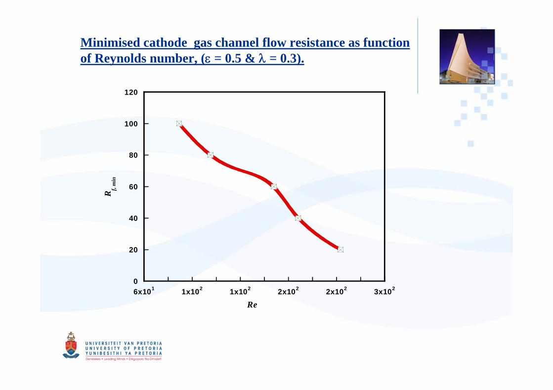
Minimised cathode gas channel flow resistance as function of Reynolds number, ( = 0.5 & = 0.3).
0
20
40
60
80
100
120
6x101 1x10² 1x10² 2x10² 2x10² 3x10²
Rf,
min
Re
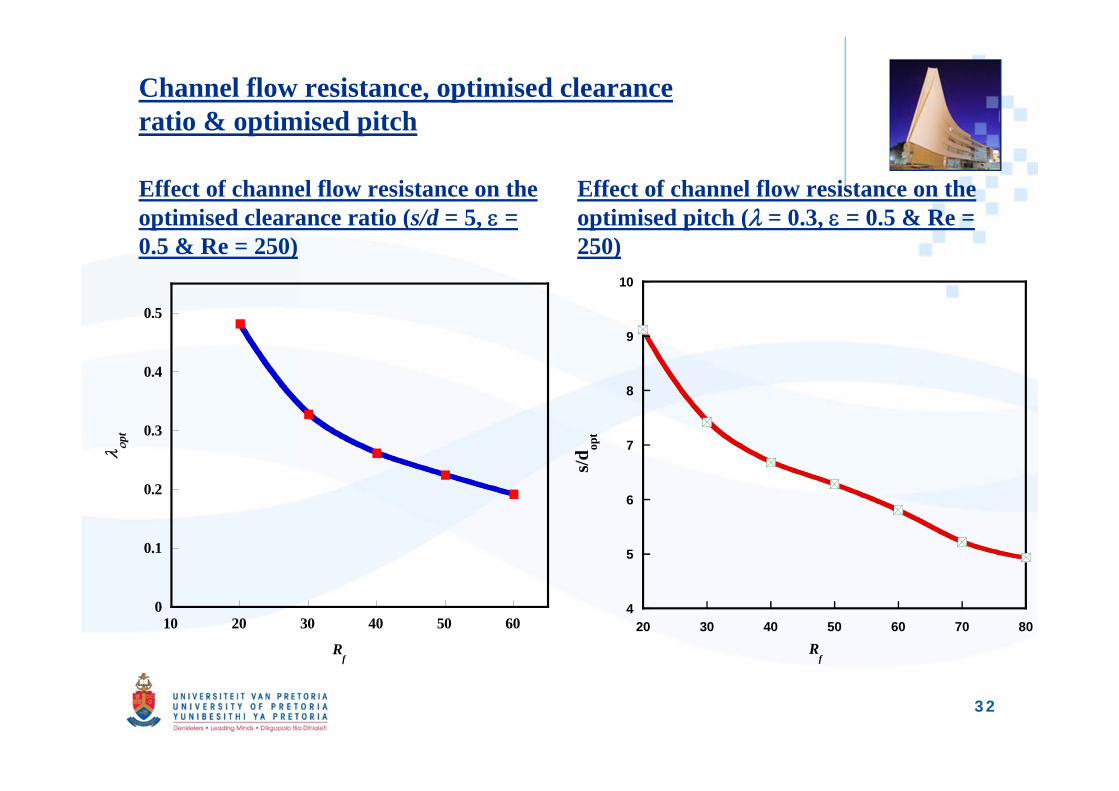
Channel flow resistance, optimised clearance ratio & optimised pitch
Effect of channel flow resistance on the optimised clearance ratio (s/d = 5, = 0.5 & Re = 250)
Effect of channel flow resistance on the optimised pitch ( = 0.3, = 0.5 & Re = 250)
0
0.1
0.2
0.3
0.4
0.5
10 20 30 40 50 60
pt
Rf
4
5
6
7
8
9
10
20 30 40 50 60 70 80
s/d op
t
Rf
32
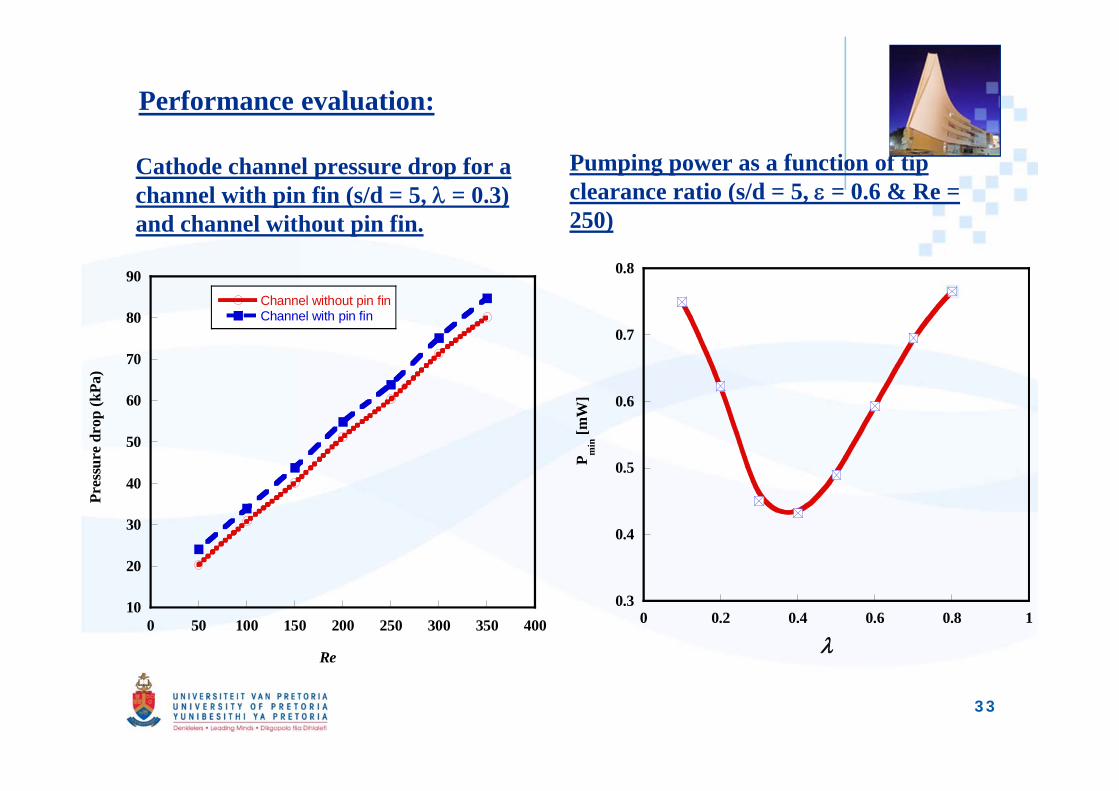
Performance evaluation:
Cathode channel pressure drop for a channel with pin fin (s/d = 5, = 0.3) and channel without pin fin.
Pumping power as a function of tip clearance ratio (s/d = 5, = 0.6 & Re = 250)
10
20
30
40
50
60
70
80
90
0 50 100 150 200 250 300 350 400
Channel without pin finChannel with pin fin
Pres
sure
dro
p (k
Pa)
Re
0.3
0.4
0.5
0.6
0.7
0.8
0 0.2 0.4 0.6 0.8 1
P min
[mW
]
33
34
Research objective 3:Previous studies in area of research (Thermal cooling for PEM fuel cell maximum performance)
• Coppo et al. (2006). Presented a 3D model to study the influence oftemperature on PEM performance. Study confirms that water transport &removal from GDL surface by temperature variation affects the systemperformance.
• Ramousse et al. (2005). Presented a numerical model accounting for heatand mass transfer. The study shows that thermal stresses are induced athigher current density of cell operation.
Issues of interest: Investigate on operating PEM fuel cell beyond the critical temperature
(~80 0C ) without special high temperature materials.
Develop a cooling channel geometry scheme for enhanced PEM fuel cell performance
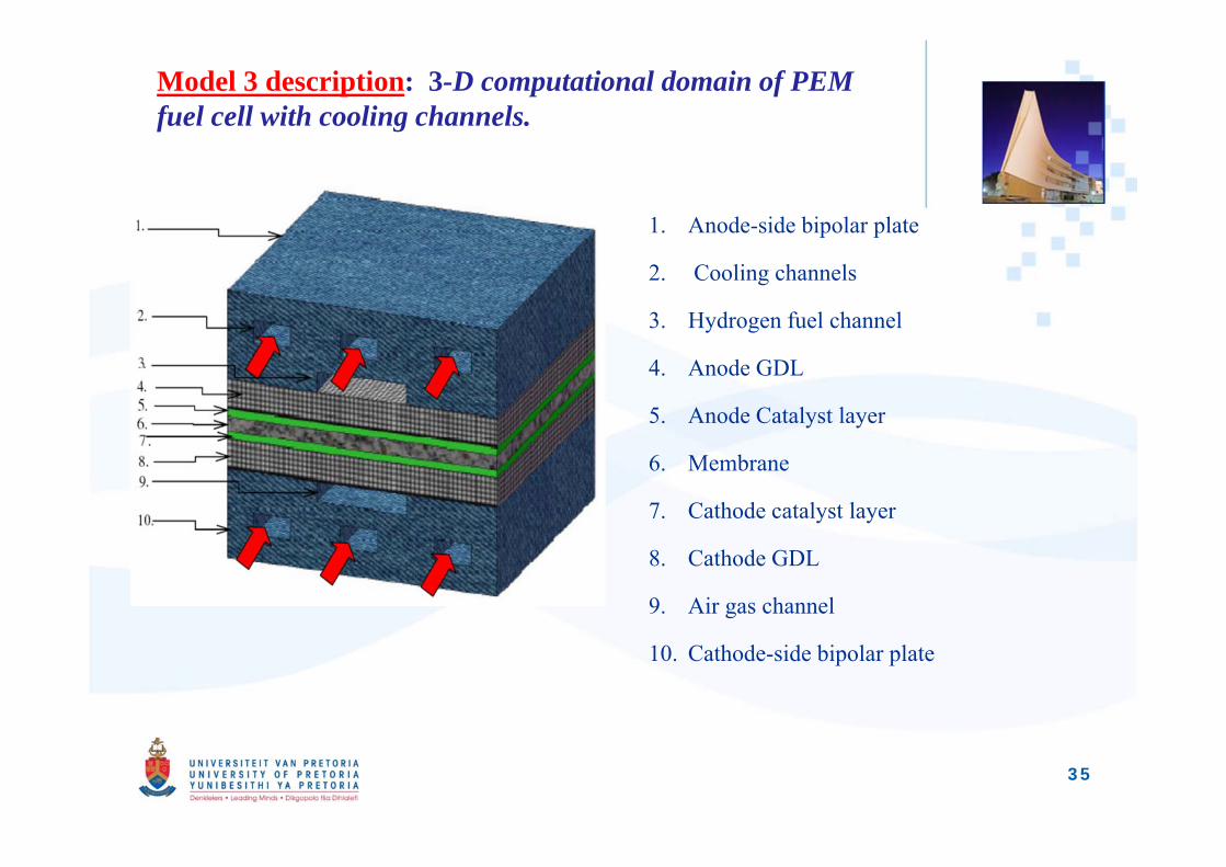
Model 3 description: 3-D computational domain of PEM fuel cell with cooling channels.
1. Anode-side bipolar plate
2. Cooling channels
3. Hydrogen fuel channel
4. Anode GDL
5. Anode Catalyst layer
6. Membrane
7. Cathode catalyst layer
8. Cathode GDL
9. Air gas channel
10. Cathode-side bipolar plate
35
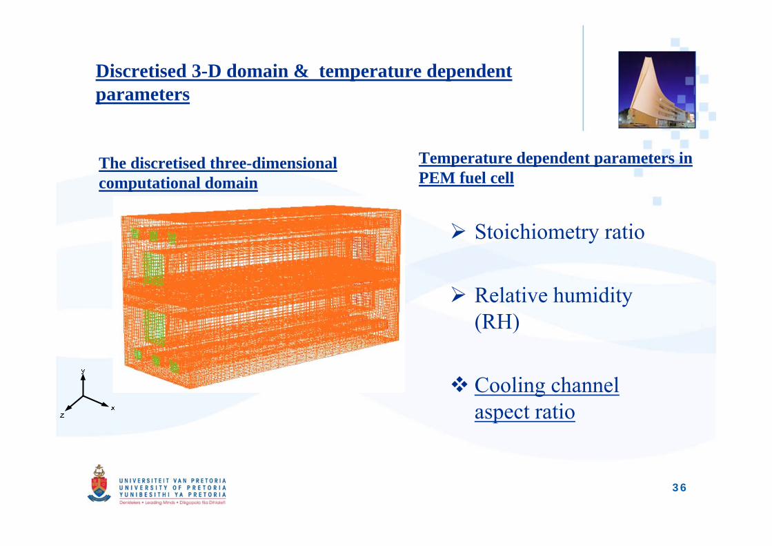
Discretised 3-D domain & temperature dependent parameters
The discretised three-dimensional computational domain
Temperature dependent parameters in PEM fuel cell
Stoichiometry ratio
Relative humidity (RH)
Cooling channel aspect ratio
36
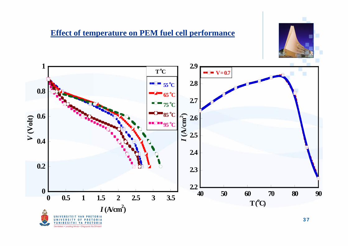
Effect of temperature on PEM fuel cell performance
0
0.2
0.4
0.6
0.8
1
0 0.5 1 1.5 2 2.5 3 3.5
55 oC
65 oC
75 oC
85 oC
95 oC
V (V
olt)
I (A/cm2)
T oC
2.2
2.3
2.4
2.5
2.6
2.7
2.8
2.9
40 50 60 70 80 90
V = 0.7
I (A
/cm
2 )
T (oC)
37
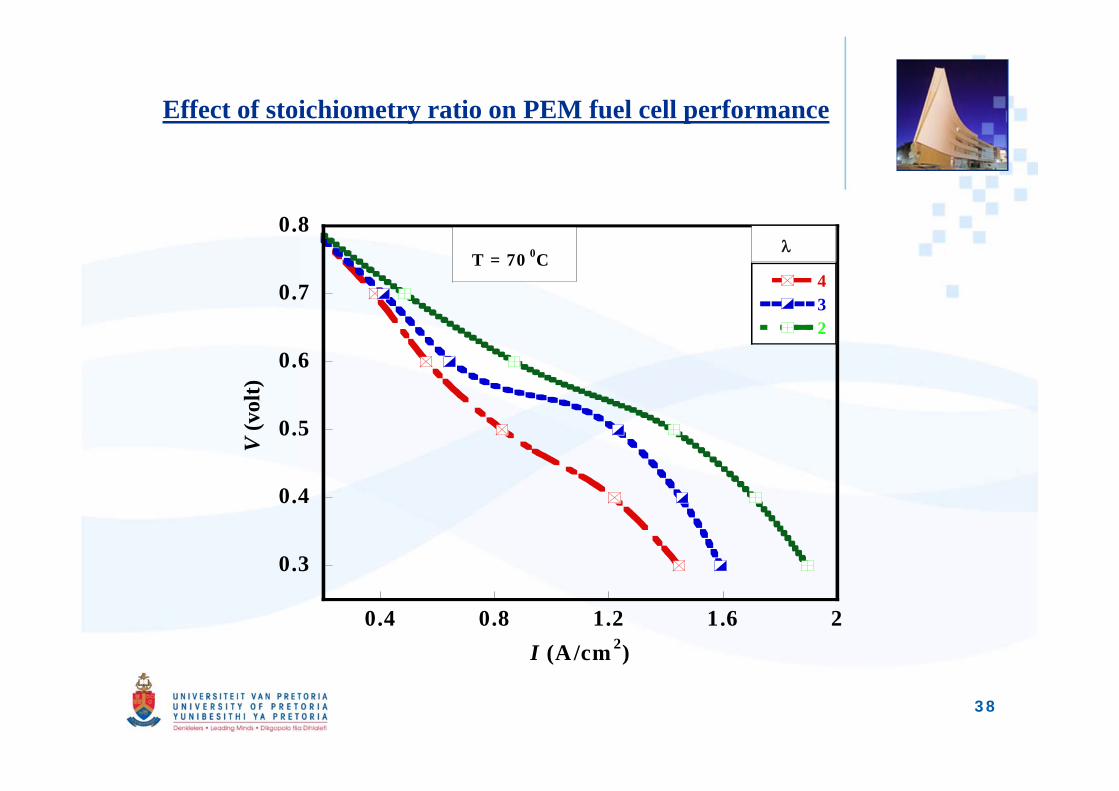
Effect of stoichiometry ratio on PEM fuel cell performance
0.3
0.4
0.5
0.6
0.7
0.8
0.4 0.8 1.2 1.6 2
432
V (v
olt)
I (A/cm 2)
T = 70 0C
38
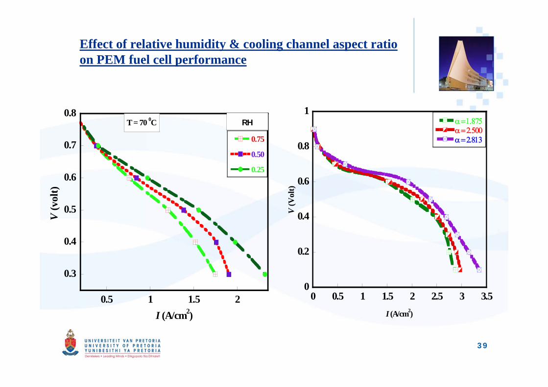
Effect of relative humidity & cooling channel aspect ratio on PEM fuel cell performance
0.3
0.4
0.5
0.6
0.7
0.8
0.5 1 1.5 2
0.75
0.50
0.25
V (v
olt)
I (A/cm2)
RHT = 70 0C
0
0.2
0.4
0.6
0.8
1
0 0.5 1 1.5 2 2.5 3 3.5
V (V
olt)
I (A/cm2)
39
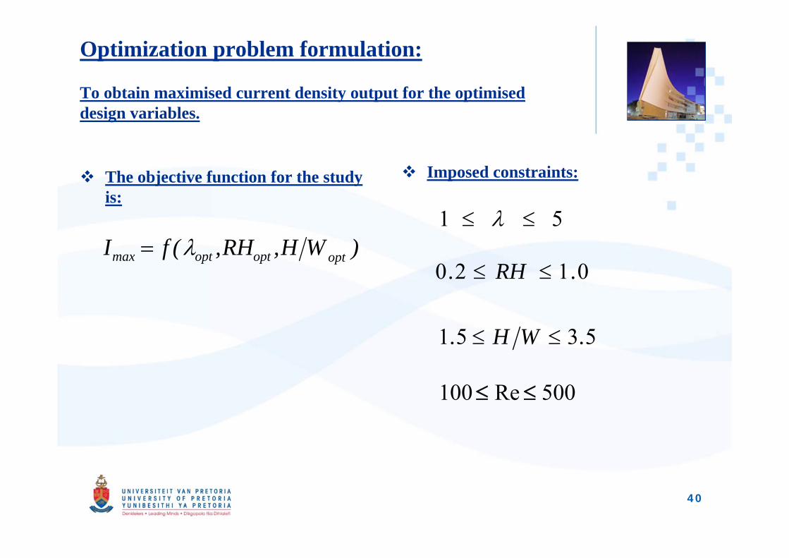
Optimization problem formulation:
To obtain maximised current density output for the optimised design variables.
The objective function for the study is:
Imposed constraints:
40
)WH,RH,(fI optoptoptmax 51
0120 .RH.
5351 .WH.
500Re100
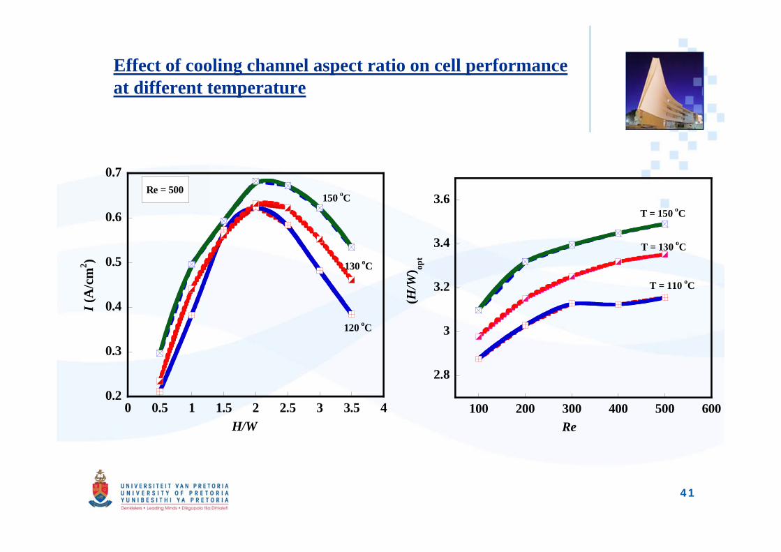
Effect of cooling channel aspect ratio on cell performance at different temperature
0.2
0.3
0.4
0.5
0.6
0.7
0 0.5 1 1.5 2 2.5 3 3.5 4
I (A
/cm
2 )
H/W
150 oC
130 oC
120 oC
Re = 500
2.8
3
3.2
3.4
3.6
100 200 300 400 500 600(H
/W) op
tRe
T = 150 oC
T = 130 oC
T = 110 oC
41
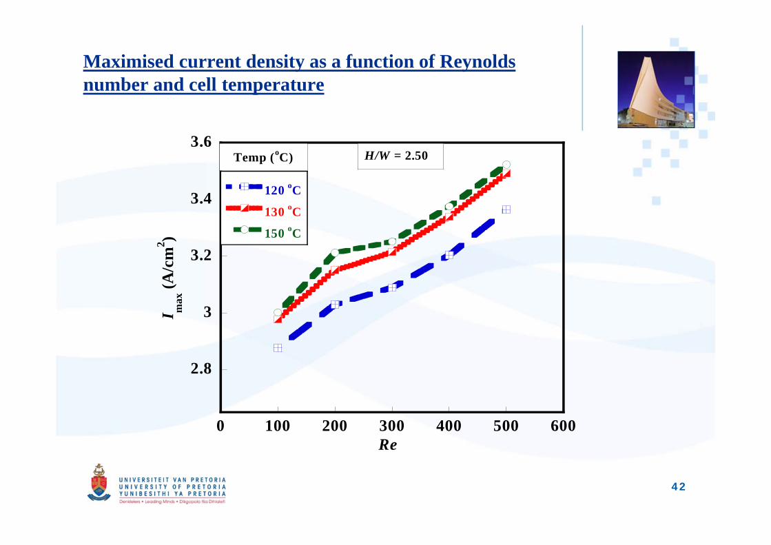
Maximised current density as a function of Reynolds number and cell temperature
2.8
3
3.2
3.4
3.6
0 100 200 300 400 500 600
120 oC
130 oC
150 oC
I max
(A/c
m2 )
Re
Temp (oC) H/W = 2.50
42
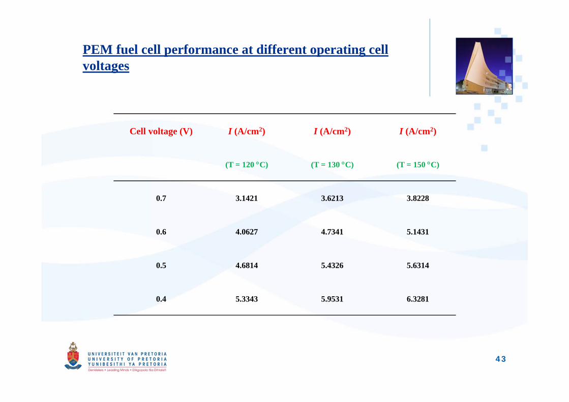
PEM fuel cell performance at different operating cell voltages
Cell voltage (V) I (A/cm2) I (A/cm2) I (A/cm2)
(T = 120 C) (T = 130 C) (T = 150 C)
0.7 3.1421 3.6213 3.8228
0.6 4.0627 4.7341 5.1431
0.5 4.6814 5.4326 5.6314
0.4 5.3343 5.9531 6.3281
43
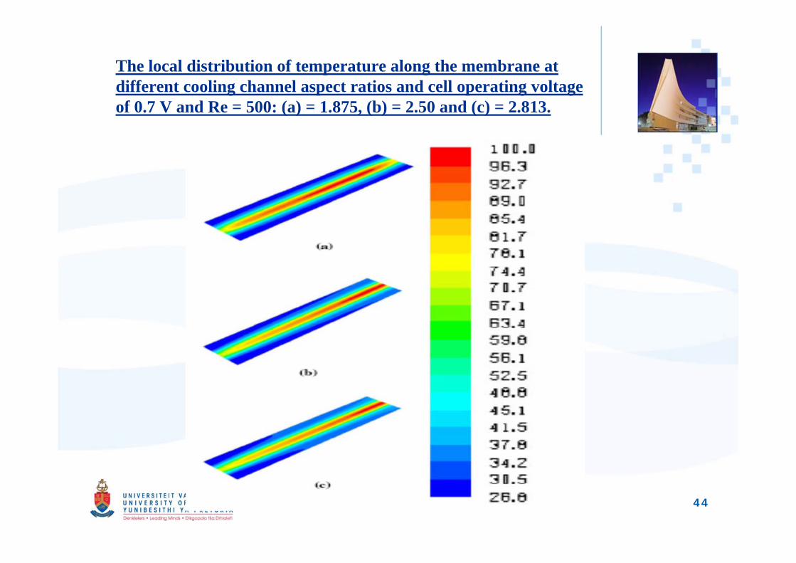
The local distribution of temperature along the membrane at different cooling channel aspect ratios and cell operating voltage of 0.7 V and Re = 500: (a) = 1.875, (b) = 2.50 and (c) = 2.813.
44
Conclusions: model case 1
• The model predictions are in good agreement withexperimental data.
• Gas diffusion layer porosity and cathode gas massflow rate affect the performance of the fuel cell.
• Porosity effect on cell performance are moresignificant at porosity levels of 0.1 to 0.4 than at 0.5 to0.7.
• The study shows that appropriate match of PEM fuelcell parameters (i.e. porosity, species mass flow ratesand channel geometry) can significantly improve fuelcell performance.
45
Conclusion: Model case 2
• The flow Reynolds number had a significant effect on thereactant flow field, and the diffusion of the reactant gas throughthe GDL medium increased as the Reynolds number increased.
• The friction factor increased with an increasing clearance ratioof the pin fin in the channel.
• The optimal clearance ratio and pitch for the considered fuel cellchannel decreased with an increase in the fuel channel friction.
• The friction factor decreased with an increase in the GDLporosity. Hence, the channel friction and pressure drop can bereduced significantly with increased GDL porosity.
46
Conclusion model case 2 contd.
• An optimal pin fin clearance ratio existed which offeredminimum pumping power requirement.
• An enhanced fuel cell performance was achieved by usingpin fins in a fuel cell gas channel, which ensured highperformance and low fuel channel pressure drop of the fuelcell system.
47
Conclusion: Model case 3
• PEM fuel cell performance is considerably enhanced when PEMfuel cells operate at combined optimised design parameters.
• Performance is more outstanding at temperatures between 120Cand 130C. However, the performance increment rate declinesgradually from 130C to 150C.
• The study shows the possibility of operating a PEM fuel cellbeyond the critical temperature range ( 80C) by using thecombined optimised stoichiometry ratio, relative humidity andcooling channel geometry.
• It should also be noted that this study can easily be extended todifferent cooling channels (apart from the rectangular channelsused in this study) in order to enhance the performance of PEMfuel.
48
Recommendation for future work
Evaluation of PEM fuel cell under different materialproperties rather than assuming isotropic & homogeneous
Need for consideration for two-phase flow in the PEM fuelcell structures to enhance modeling results.
Large scale simulations using parallel computing will reducecomputational time especially in model with multi-parameter evaluation.
Experimental validation of results in standard fuel cell teststations to enhance model result implementation.
49
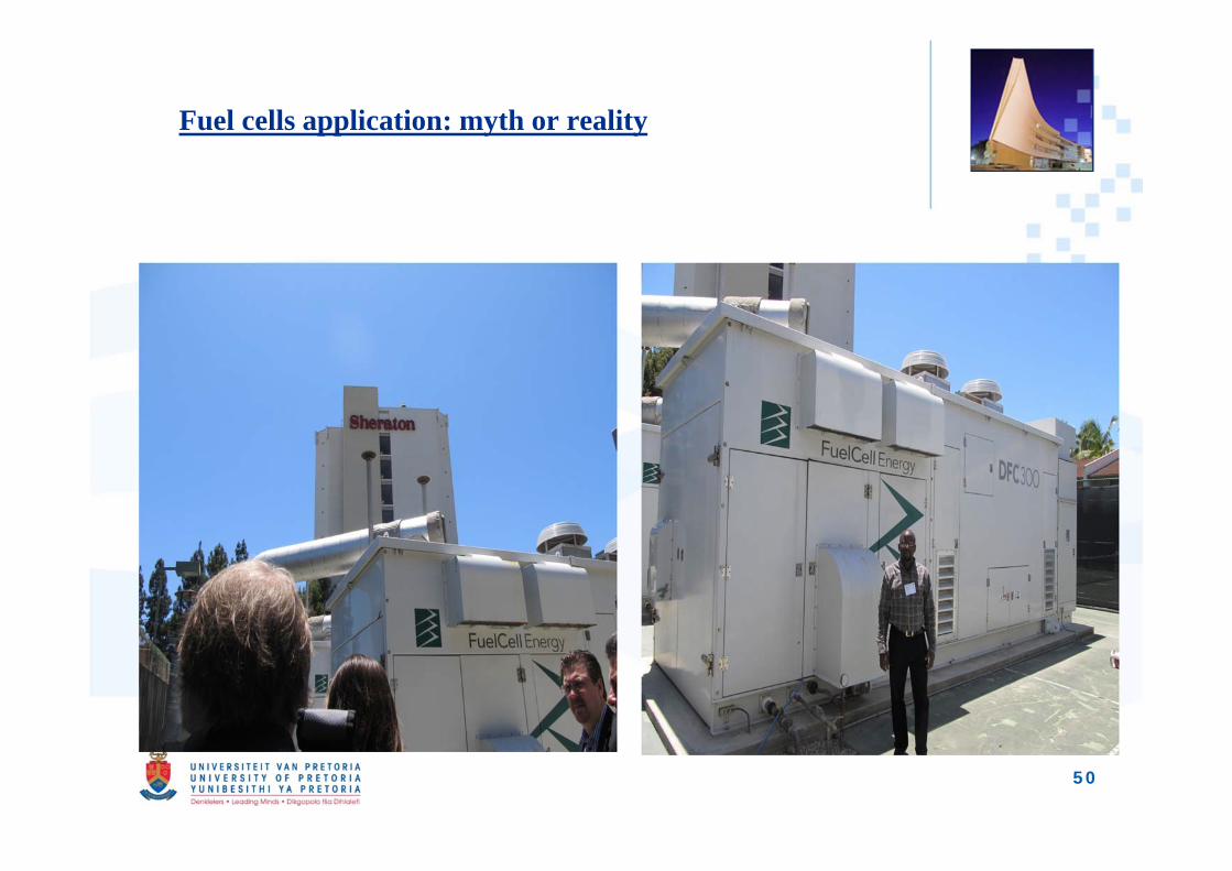
Fuel cells application: myth or reality
50
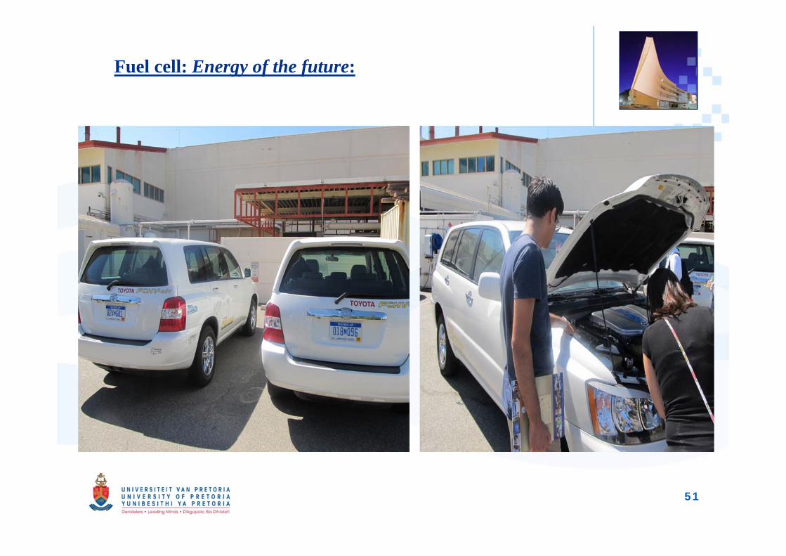
Fuel cell: Energy of the future:
51
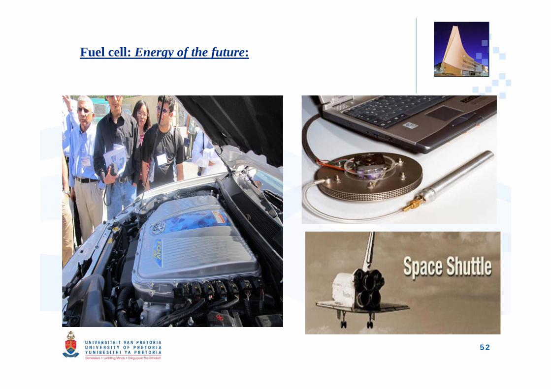
Fuel cell: Energy of the future:
52
List of Publications from the study:
• S.O Obayopo, T.Bello-Ochende, J.P. Meyer (2011); Three-dimensionaloptimization of a fuel gas channel of a PEM fuel cell for maximum currentdensity, International Journal of Energy Research (Wiley Science) paper no:DOI:10.1002/er.1935. Impact factor: 2.122
• S.O. Obayopo, T. Bello-Ochende, J.P. Meyer (2012), ‘Modelling andoptimization of reactant gas transport in PEM fuel cell with transverse pinfin insert in channel flow’, International Journal of Hydrogen Energy 37(13):10286-10298. Impact factor: 4.054
• T. Bello-Ochende, S.O. Obayopo, J.P. Meyer, ‘Conceptual design of highcurrent density PEM fuel cell with optimized cooling channels’ – underreview.
• S.O. Obayopo, T. Bello-Ochende, J.P. Meyer, ‘Impact of Cooling ChannelGeometry on Thermal Management and Performance of a Proton ExchangeMembrane Fuel Cell’, Proceeding of the 9th International Conference on HeatTransfer, Fluid Mechanics and Thermodynamics, HEFAT 2012, 16-18 July2012,Malta
53
List of Publications contd:• S.O. Obayopo, T. Bello-Ochende, J.P. Meyer, ‘Numerical Study and Optimisation
of Channel Geometry and Gas Diffusion Layer of a PEM Fuel Cell’, Proceedings ofthe ASME 2012 6th International Conference on Energy Sustainability & 10th FuelCell Science, Engineering and Technology Conference ESFuelCell2012, July 23-26,San Diego, CA, USA.
• S.O. Obayopo, T. Bello-Ochende, J.P. Meyer, ‘Optmising the Performance of aPEM Fuel Cell with Transverse Fins Insert in the Channel Flow using MathematicalAlgorithm’, Proceedings of the ASME 2012 6th International Conference on EnergySustainability & 10th Fuel Cell Science, Engineering and Technology ConferenceESFuelCell2012, July 23-26, San Diego, CA, USA.
• S.O. Obayopo, T. Bello-Ochende, J.P. Meyer, ‘Numerical Study of effect of designand physical parameters on a PEM fuel cell performance’, Proceeding of the 8th
International Conference on Heat Transfer, Fluid Mechanics and Thermodynamics,HEFAT 2011, pp 567, Pointe Aux Piments, Mauritius, 11-13 July 2011.
• S.O. Obayopo, T. Bello-Ochende, J.P. Meyer, ‘Thermodynamic Optimization of PEM Fuel Cell Stack Gas Channel for Optimal Thermal Performance’, Proceeding of the 14th “International Heat Transfer Conference (ASME), IHTC-14, paper no. IHTC14-22233 Washington DC USA, 8-13 August 2010.
54
List of Publications contd:
• S.O. Obayopo, T. Bello-Ochende, J.P. Meyer, ‘Numerical Optimization of aSingle PEM Fuel Cell under Variable Operating Conditions’, Proceeding ofthe 7th International Conference on Heat Transfer, Fluid Mechanics andThermodynamics, HEFAT 2010, pp 667-672, Antalya Turkey, 19-21 July 2010.
• S.O. Obayopo, T. Bello-Ochende, J.P. Meyer, ‘Thermodynamic Optimizationof Proton Exchange Membrane Fuel Cell System’, Proceeding of the 1st
National symposium on Renewable and Sustainable Energy Center for Renewableand Sustainable Energy Studies, NCRS2010, Paper no. NCRS017. pp 1-15.Stellenbosh South Africa, 11-12 November 2010
• S.O. Obayopo, T. Bello-Ochende, J.P. Meyer, ‘Performance enhancement ofPEM fuel cell through reactant gas channel and gas diffusion layeroptimization’, Proceeding of the 2nd National symposium on Renewable andSustainable Energy Center for Renewable and Sustainable Energy Studies,NCRS2011, Paper no. NCRS010. pp 1-15.Stellenbosh South Africa, 17-18November 2011.
55
Appreciation:
My supervisors (Prof. T. Bello-Ochende & Prof. J.P. Meyer)
Prof. J.A. Snyman.
All academic & non-academic staff of Department of Mechanical Engineering University of Pretoria.
My family: Rofiat , Abdul-Rahman, Mar’yam & Ibrahim.
All research students and friends.
Advanced Engineering Centre of Excellence at the University of Pretoria, NRF, TESP, NAC, the SOLAR Hub with the Stellenbosch University, EEDSM Hub and the CSIR.
56

57