Quantum Versus Chaos - Questions From Mesoscopy - K. Nakamura

Performance comparison between Chaosand quantum-chaos based imageencryption techniques
Manju Kumari1 & Shailender Gupta1
Received: 29 August 2020 /Revised: 15 January 2021 /Accepted: 24 June 2021
# The Author(s), under exclusive licence to Springer Science+Business Media, LLC, part of Springer Nature 2021
AbstractToday’s digital era has undertaken most of the responsibilities of public and privatesectors, not only the industries or big organizations dependent on the internet butindividual’s household needs also lying on it. To make the data transmission/receptionconfidential and secure for both internet users and internet service providers, a largenumber of researches have been done in this field. It has proved that cryptography is thebest solution for solving this purpose. Mostly, digital images are continuously transferringon the network rather than texts. Enciphering a digital image is a much bulkier and acomplex task. It has been evident from many types of research that chaotic logistic map-based equations provide a great level of randomness. Hence Chaotic logistic maps-basedimage encryption techniques (also called chaos techniques) were implemented to obtainhighly random cipher images. On the other hand, time consumption must be as low as itcan be possible to sustain real-time communication. Presently, the advanced encryptionschemes based on quantum technology have enhanced efficiency and security because ofhaving a large key-space and less time complexity along with randomness. The quantum-chaos based encryption is done by utilizing uncertainty principles of quantum mechanicson logistic maps. This paper is an effort to compare chaos and quantum chaos-basedimage encryption schemes. MATLAB 2016a software is used for the execution and thecomparison is made based on various security attack analyses. Based on the study andexperimental results, the quantum chaos techniques used for bit plane scrambling pro-vides better results in terms of effectiveness, efficiency, and trustworthy that can beadopted for highly secured image encryption.
Keywords Cryptography . Security attacks . Chaos techniques . Encryption . Quantum-chaostechniques
https://doi.org/10.1007/s11042-021-11178-3
* Manju [email protected]
Extended author information available on the last page of the article
Published online: 14 August 2021
Multimedia Tools and Applications (2021) 80:33213–33255
/

1 Introduction
In the recent past, the augmented usage of the internet has risen the cases of hacking, intrusion,cyberstalking, and many more unauthorized accesses. We can depict this from the reportpublished last year by CISCO cybercrime survey, it is mentioned that the number of attackshas grown by Malware (20%), Data breach (19%), Spyware (14%), Phishing (13%),Ransomware (13%), Malicious spam (13%) [1].
The intruder’s consistent involvement on the internet urges the need to enhance the securitylevel [2]. During this pandemic situation of COVID-19, as most of the activities of private andgovernment sector has shifted from their organization’s secured intranet to the globallyconnected internet, hence the solutions from the threat of being hacked are in demand now.
Therefore, researchers are continuously working on the development of novel securitytechniques [3, 4]. It is evident in previous researches that adopting cryptography is the bestsolution for cyber-security [5]. Cryptography is the technique of transforming original datainto an unreadable form before transmission and recovering the original data from its ciphers atthe receiver [6]. To secure data communication numerous techniques have been developed.Initially, the internet was used only for the transmission of text files in the form of emails. Thebits representation of text data is very random and limited. But from few decades due to theincrease in various multimedia applications, mostly data are transferring in the form of digitalimages that are bulky and linear. It means most of the information represented in an image aresymmetrically correlated with its neighbor pixel.
The traditional cryptography techniques like DES [8], TDES [9], AES [10], BLOWFISH[11], RC4 [12], RC5, etc. are highly efficient, secure, and fast for text files only. If we usethese encryption techniques on image files, the schemes consume a large time and generate aless random cipher image. That’s why chaos-based encryption techniques have been proposedby the researchers to get better results in image encryption in terms of randomness and timecomplexity. The chaotic-maps used in chaos-based image encryption schemes possess non-linear characteristics that result in a highly randomized image. The schemes consume less timeonly for small size data, for big size image the execution time is not sufficient for real-timecommunication. All the chaos-based techniques cover two major operations, one is for pixelposition scrambling called the confusion process and another one is the diffusion process usedto modify pixel values. The techniques always use the basic logistic map to generate chaotickeys and also to modify pixel positions or values of the original image.
The equation of the logistic map is represented in sr. no. 1 of Table 2. when n = 0, the initialvalue of ×0 must be assigned in between 0 to 1. μ is a sequence control parameter whose valuemust be lies in between 0 to 4, to generate highly random sequence xn. But the map also hassome weaknesses like the formation of a blank window when μ = 3.828, stable window,uneven distribution of sequences, and a weak key [15]. That’s why we always consider μ =3.999 in these experiments. Hence to overcome the drawbacks, researches on quantum-basedencryption techniques is going on currently. The basic idea about the development of thesekinds of techniques is that the information traveled on the internet must be random at itsmaximum extend. This is done by utilizing uncertainty principles of quantum mechanics onlogistic maps which can enhance the randomness property of a ciphered image.
So, when the quantum behavior of the Heisenberg equation of wave motion [16] wasapplied on chaotic logistic maps, the cryptosystem became highly random because of gainingthe qualities of high sensitivity to initial conditions and control parameters, mixing property,high efficiency, and non-periodicity. These properties of the quantum logistic map tend to
33214 Multimedia Tools and Applications (2021) 80:33213–33255

enhance the randomness and time complexity with a large key-space. The higher the keysensitivity lesser will be the image perceptual quality and the lesser will be the chance ofinformation to be retrieved on the way of a communication channel. The mathematicalrepresentation of the quantum chaotic map is given in sr. no.2 of Table 2.
The equation has all the above-mentioned capabilities but this does not serve the purposealone, we still needed to analyze them in some well-known performance analyses likeRobustness analysis, security analysis, and attacks analysis [17].
To solve the purpose a survey of already published encryption techniques based reviewpaper has been studied. The surveyed research papers are shown in Table 1. A survey offourteen encryption techniques has been theoretically analyzed by John Justin M et.al [7]. Theauthor did not consider any performance metrics for analysis against attacks on noises. In2013, B. Padmavathi et.al [13] surveyed the most popular traditional techniques i.e. DES,AES, and RSA encryption techniques. The authors have also performed an analysis of theabove mentioned techniques along with the LSB substitution technique. They provide exper-imentally analysis and comparison in a very effective way. They considered plain and chosenattacks but more attacks need to be considered for better security. Sourabh Chandra et.al hassurveyed various symmetric and asymmetric key cryptography techniques [15]. The authorhas done a comparative analysis of studied encryption techniques without any consideration ofnoise attacks. Garima Tanwar et.al did a comparative analysis of ten image encryptiontechniques [14]. They have done comparisons based on theoretical and experimental analysisby calculating various performance metrics. This paper also did not include the main factor ofsecure encryption technique which is attacks analysis. Kevadia, K. T et.al [27] have done atheoretical survey of fifteen image encryption techniques. This paper includes a comparisonwithout considering attacks and performance metrics. Omar Farook Mohammad et.al [19]have done the experimental analysis of nine encryption techniques. They performed a com-parison but did not consider any noise attacks as one of the parameters. Manju Kumari et.al[26], performed a survey and experimental analysis of fifteen image encryption techniques.But in this paper also noise attack analysis has not been included. Pandya, A. et.al [34], hasperformed a theoretical survey and comparative analysis of three encryption techniqueswithout considering an attack. Younes, M.A.B et.al [35], has performed a survey of the latestfourteen image encryption techniques theoretically without considering any performancemetrics and attacks analysis. Patel, S. et al. [36] have surveyed twenty image encryptiontechniques with compression sensing. This survey was theoretically analyzed without consid-ering any performance metrics and attacks on various noises. Manish Kumar et.al [37]performed a theoretical survey of twenty-four image encryption techniques.
The researchers have compared various image encryption techniques but only a few papersare available which provides a comparison of many traditional and modern encryptiontechniques. It clearly shows that existing papers have provided limited details of cryptographytechniques which can provide experimental details of multiple noises and attacks.
Thus, this paper is an effort for the following contributions:
& Most of the latest encryption algorithms including chaos and quantum chaos-based imageencryption techniques are taken into consideration for analysis.
& Analysis of algorithms is performed meticulously by considering various kinds of com-prehensive attacks with and without consideration of noises.
33215Multimedia Tools and Applications (2021) 80:33213–33255

Table 1 Available survey papers in literature survey
Author Title Year No. of TechniquesCompared
Mode of Comparisonon Performancemetrics
SecurityAttacksAnalysis
John JustinM et al.[7]
A Survey on VariousEncryptionTechniques
2012 14 techniques Theoretically analyzed Not done
B.Padmava-thi et al.[13]
A Survey onPerformanceAnalysis of DES,AES and RSAAlgorithm alongwith LSBSubstitutionTechnique
2013 3 techniques Experimentallyanalyzed with thehelp of algorithmtype, Key length,Encryption Ratio,Scalability,Stimulation Speed,Power Consumption,Key used, Hardwareand Softwareimplementation
SecurityAttacksana-lyzed:plaintext,cipher-textattacks
SourabhChandraet.al [15]
A comparative surveyof symmetric andasymmetric keyCryptography
2014 42 techniques(Symmetric keyCryptography,Asymmetric keyCryptography, newlyproposed Symmetrickey and Asymmetrickey Cryptographytechniques)
Theoretically analyzedwith the help of:
1. SYMMETRIC KEYCRYPTOGRAPHY:Structure ofalgorithm, Blocksize, Key size,Vulnerabilities,Efficiency
2. ASYMMETRICKEYCRYPTOGRAPHY:Feature, Advantages,Disadvantages,Security solutions
3. NEWLYPROPOSEDSYMMETRIC KEYANDASYMMETRICKEYCRYPTOGRAPHY:Characteristics,Advantages, Pitfalls,Implementations
Not done
GarimaTanwaret al. [14]
Survey on ImageEncryptionTechniques
2015 10 techniques Theoretically andExperimentallyanalyzed with thehelp ofImperceptibility,Visual Degradation,Compressionfriendliness, Speed,Key space, KeySensitivity analysis,Histogram analysis,Statistical analysis,Correlationcoefficient analysis,Encryption Quality
Not done
33216 Multimedia Tools and Applications (2021) 80:33213–33255

& Performance metrics are calculated for the examination of the studied encryption tech-niques to get the best technique even in noisy channels. Security analysis, Robustnessanalysis under the influences of noises and attacks are executed for comparison.
& A comparison has been made, and the best technique is identified from the survey with andwithout the presence of attack and noises.
In this paper, various chaos-based and quantum chaos-based image encryption techniqueshave studied theoretically and experimentally besides Robustness analysis, security analysis,and attacks analysis. For robustness analysis, several performance metrics such as Peak Signal
Table 1 (continued)
Author Title Year No. of TechniquesCompared
Mode of Comparisonon Performancemetrics
SecurityAttacksAnalysis
Kevadia,K.T. et.al[27]
A Literature Survey onImage Encryption.
2016 15 techniques Theoretically analyzed Not done
OmarFarookMoham-mad et.al[19]
Survey and Analysis ofthe ImageEncryption Methods
2017 9 techniques Experimental Analysisis done on VisualAssessment, Keyspace analysis,Statistical analysisand Differentialanalysis, Entropy,PSNR withComputationalSpeed
Not done
ManjuKumariet.al [26]
A Survey of ImageEncryptionAlgorithms
2017 15 techniques Experimentallyanalyzed with thehelp of VisualAssessment,Statistical andDifferential analysis,Key space and Keysensitivity analysis,Quantitativeanalysis, Timecomplexity
Not done
Pandya, A.et.al [34]
Comparative Analysisof EncryptionTechniques
2018 3 techniques Theoretically analyzedwith the help of keysize, Block size,Cipher type andsecurity
Not done
Younes,M.A.B.[35]
A Survey of the mostcurrent imageencryption anddecryptiontechniques
2019 14 techniques Theoretically analyzed Not done
Patel, S. et.al[36]
A systematic survey onImage Encryptionusing CompressiveSensing
2020 20 techniques Theoretically analyzed Not done
ManishKumaret.al [37]
Review of ImageEncryptionTechniques
2020 24 techniques Theoretically analyzed Not done
33217Multimedia Tools and Applications (2021) 80:33213–33255

to Noise Ratio (PSNR), Entropy, Correlation (horizontally, vertically, and diagonally) havebeen analyzed with some predefined values. For security analysis performance metrics likeVisual representation of encrypted/decrypted images, Key Space, and time complexity areobserved. Lastly, for attacks analysis several parameters are examined like: Unified AverageChanging Intensity (UACI), Number of pixel change Rate (NPCR) [18], noise(salt & pepper,gaussian, speckle, Poisson’s) attacks.
The rest of the paper is organized as follows: in the section-II, six chaos-based and sixquantum chaos-based latest image encryption techniques or schemes has been theoreticallyexplained with the help of block diagrams. Section-III provides simulation set-up parametersalong with performance matrices used to evaluate the efficacy of the studied techniques.Section IV gives the results with comparison and it is followed by a conclusion in section-V.
2 Image encryption techniques
As mentioned in the previous section that chaos and quantum chaos image encryptiontechniques are well enough for providing confidentiality services to internet users for real-time communication services. These methods directly modified the pixel positions and pixelvalues to maintain a large range of randomness. All of the studied techniques lied under thecategory of symmetric key cryptography techniques. These techniques have two majorprocesses: Confusion and Diffusion [20]. The confusion process is meant for pixel positionmodification and the diffusion process modifies the pixel values. Several iterations of confu-sion and diffusion process have been provided to obtain higher order of randomness and lessertime complexity. The studied encryption techniques are random and confusing because of thepresence of complex mathematics and its application to its various processes. Hence, for betterunderstanding, Table 2 is provided which contains a series of maps and their correspondingequations along with a detailed description of the parameter’s symbol and their range ofvalues.
In this section, six studied and latest developed chaos and six quantum chaos techniques aretried to be explained as follows:
2.1 Chaos scheme 1: An intertwining chaotic maps based image encryption scheme
A concept of a modified classical logistic map was introduced by Sam et al. [21] in 2012. Theauthor named it as intertwining chaotic maps which are used for the generation of chaotic keysand utilized to perform confusion and diffusion processes of encryption. These maps havehighly random properties than a classical logistic map. The complete cryptosystem consists offour encryption processes: permutation to change the pixel value, byte substitution to enablethe confusion process, nonlinear diffusion, and sub-diagonal diffusion along with key gener-ation. Three sets of chaotic keys (x,y, and z) have been generated to encrypt the R, G, and Bplane with the help of proposed intertwining logistic maps as represented in sr. no. 2 ofTable 2.
Each map is iterated m*n times (size of a plane of the original image) such that a sequenceof the compatible size of the plain image can be generated. In the confusion process, firstlyinitial permutation is carried out to scramble the pixel positions with the help of predefined sixrandom values and then the resulting image is XORed with the first chaotic key(x). After thispixel values have been substituted with the help of S-box (16 × 16) as used in AES [10] and
33218 Multimedia Tools and Applications (2021) 80:33213–33255

Table2
Listof
MapsandtheirEquations
used
forencryptio
nschemes
Sr.
No.
Nam
eof
Map
sEqu
ations
Symbo
lof
Con
trol
Param
eter
Nam
eof
Con
trol
Param
eter
Ran
ge
1Logistic
Map
x n+1=μx n(1-x
n)μ
Sequence
Control
Parameter
[0,4]
2Intertwininglogisticmaps
x n+1=[μ.k
1.y n(1-x
n)+z n]mod
1y n
+1=[μ.k
2.y n+z n(1/(1-x n
+1)2 ]
mod
1z n
+1=[μ.(x n
+1+
y n+1+
k 3).sin(z n)]mod
1
μSequence
Control
Parameter
[0,4]
k 1Floatvalueas
multip
lier
>33.5
k 2Floatvalueas
multip
lier
>37.9
k 3Floatvalueas
multip
lier
>35.7
x 0Initialvalueof
x0.41324738544344
y 0Initialvalueof
y0.52638928350638
z 0Initialvalueof
z0.98644737157579
p1,p2,p3,p4,p5,p6
Sixoddrandom
values
1,5,99,111,7,77
3Chaoticfunctio
nx n
+1=[[x n
2 ]mod
S].x
n+x g]
mod
SI 0b
Transform
edbinary
1Dvector
oforiginalmonochrom
eim
age
SLengthof
image
Binarysize
of(I0b)-1
Gpseudo-random
seed
{1,...,
Binarysize
of(I0b)}
x 0Initialvalueof
xG
x gpseudo-random
seed
g24
Mixed
transformed
logicmaps
x n+1=[a.(1+x n)2.k
1.sin(1/1+
(yn)2 )]mod
1y n
+1=[a.x
n+1.k2.sin(x
n+1.
y n).(1+(z
n)2 )]mod
1z n
+1=[a.x
n+1.k3.(1+y n
+1.z
n)]
mod
1
ASequence
Control
Parameter
0<a≤3.999
k 1Predefined
keys
>37.7
k 2Predefined
keys
>39.7
k 3Predefined
keys
>37.2
5Peter
dejong
chaotic
map
andRC4
x i+1=[sin(a.y
i)-cos(b.x i)]
y i+1=[sin(c.x
i+1)-cos(d.x i)]
a,b,c,d
Control
Param
eter
0to
1.8
6Sine
Map
x n+1=sin(π.x
n)7
Quantum
logisticmap
x n+1=r[((x n)-|xn|2)-y n]
y n+1=−y
ne-2β+e-βr[(2-x
n–x
n*)
y n–x
nz n*-x n*z n)]
z n+1=−z
ne-2β+e-βr[(2–x n*)
z n-2x n
y n–x n]
x(0),y
(0),z(0)
pre-definedinitialvalues
[0,1]
x n*
Conjugateandfixedvalues
ofx
0.002
z n*
Conjugateandfixedvalues
ofz
0.004
Rcontrolparameter
[0,4]
βdissipationparameter
>=6
82-D
ToralAutom
or-phism
Map
MWidth
ofdiscretelattice
256
a11
Matrixvalueof
Catmap
1
33219Multimedia Tools and Applications (2021) 80:33213–33255

Table2
(contin
ued)
Sr.
No.
Nam
eof
Map
sEqu
ations
Symbo
lof
Con
trol
Param
eter
Nam
eof
Con
trol
Param
eter
Ran
ge
rnþ1
ðÞ
snþ1
ðÞ
�� ¼
a11
a12
a21
a22
��
rnðÞ
snðÞ
�� M
odMðÞ
a12,
a21
Matrixvalueof
Catmap
1a22
Matrixvalueof
Catmap
1+a12a21
9Couplingof
thetwo-dimensionallogistic
map
andQuantum
chaotic
map
Two-dimension
allogistic
map
:Ø(x
n)=μ1x n(1-x n)+
1y n
2
Ø(y
n)=μ2y n(1-y n)+
2(x n
2+x n
y n)
Qua
ntum
chaoticmap
:x n
+1=(1-Ɛ)Ø(x
n)+ƐØ(y
n)y n
+1=(1-Ɛ)Ø(y
n)+ƐØ(x
n)
μ1
Control
Param
eter
2.75
<μ1≤3.4
μ2
Control
Param
eter
2.75
<μ2≤3.45
1Control
Param
eter
0.15
<1≤0.21
2Control
Param
eter
0.13
<2≤0.15
ƐCouplingconstant
[0,1]
105-D
hyperchaotic
map
alongwith
quantum
cross-exchange
ofnqubit
5-D
Hyp
er-cha
oticsystem
:x 1(i+1)=a[x 2(i)-x 1(i)]+x 4(i)+
x 5(i)
x 2(i+1)=c
x 1(i)-x1(i)×3(i)-x
2(i)
x 3(i+1)=x 1(i)x
2(i)-bx 3(i)
x 4(i+1)=−x
1(i)x 3(i)+
px4(i)
x 5(i+1)=qx
1(i)
a,b,
c,pandq
Lyapunovexponentsparameter
10,8
/3,2
8,1.3and
2.5
x1(0),x2
(0),x3
(0),
x4(0)andx5
(0)
Initialvalues
0.325,0.476,1.256,
0.628,
and1.5
33220 Multimedia Tools and Applications (2021) 80:33213–33255
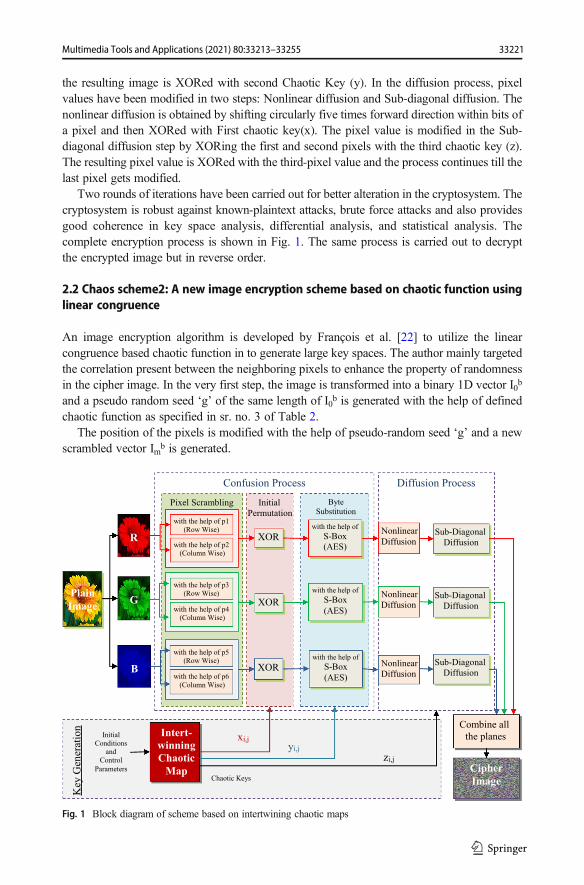
the resulting image is XORed with second Chaotic Key (y). In the diffusion process, pixelvalues have been modified in two steps: Nonlinear diffusion and Sub-diagonal diffusion. Thenonlinear diffusion is obtained by shifting circularly five times forward direction within bits ofa pixel and then XORed with First chaotic key(x). The pixel value is modified in the Sub-diagonal diffusion step by XORing the first and second pixels with the third chaotic key (z).The resulting pixel value is XORed with the third-pixel value and the process continues till thelast pixel gets modified.
Two rounds of iterations have been carried out for better alteration in the cryptosystem. Thecryptosystem is robust against known-plaintext attacks, brute force attacks and also providesgood coherence in key space analysis, differential analysis, and statistical analysis. Thecomplete encryption process is shown in Fig. 1. The same process is carried out to decryptthe encrypted image but in reverse order.
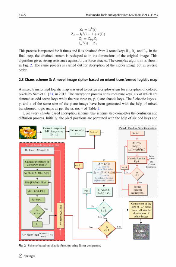
2.2 Chaos scheme2: A new image encryption scheme based on chaotic function usinglinear congruence
An image encryption algorithm is developed by François et al. [22] to utilize the linearcongruence based chaotic function in to generate large key spaces. The author mainly targetedthe correlation present between the neighboring pixels to enhance the property of randomnessin the cipher image. In the very first step, the image is transformed into a binary 1D vector I0b
and a pseudo random seed ‘g’ of the same length of I0b is generated with the help of definedchaotic function as specified in sr. no. 3 of Table 2.
The position of the pixels is modified with the help of pseudo-random seed ‘g’ and a newscrambled vector Imb is generated.
Plain Image
Confusion Process
R
G
B
Diffusion Process
Sub-Diagonal
Diffusion
Nonlinear
Diffusion
Sub-Diagonal
Diffusion
Nonlinear
Diffusion
Sub-Diagonal
DiffusionNonlinear
Diffusion
Initial
Permutation
XOR
XOR
XOR
Pixel Scrambling
with the help of p1
(Row Wise)
with the help of p2(Column Wise)
with the help of p3
(Row Wise)
with the help of p4(Column Wise)
with the help of p5(Row Wise)
with the help of p6
(Column Wise)
Byte
Substitution
with the help of
S-Box
(AES)
with the help of
S-Box
(AES)
with the help of
S-Box
(AES)
Key
Gen
erat
ion
Initial
Conditions and
Control
Parameters
Intert-winning Chaotic
Map
xi,j
yi,j
zi,j
Chaotic Keys
Combine all
the planes
Cipher Image
Fig. 1 Block diagram of scheme based on intertwining chaotic maps
33221Multimedia Tools and Applications (2021) 80:33213–33255
Z1 ¼ I0b ið Þ
Z2 ¼ I0b iþ 1þ x ið Þð Þ
Z3 ¼ Z1⊕Z2
Imb ið Þ ¼ Z3
This process is repeated for R times and R is obtained from 3 round keys R1, R2, and R3. In thefinal step, the obtained stream is reshaped as in the dimensions of the original image. Thisalgorithm gives strong resistance against brute-force attacks. The complex algorithm is shownin Fig. 2. The same process is carried out for decryption of the cipher image but in reverseorder.
2.3 Chaos scheme 3: A novel image cipher based on mixed transformed logistic map
Amixed transformed logistic map was used to design a cryptosystem for encryption of coloredpixels by Sam et al. [23] in 2012. The encryption process consumes nine keys, six of which aredenoted as odd secret keys while the rest three (x, y, z) are chaotic keys. The 3 chaotic keys x,y, and z of the same size of the plane image have been generated with the help of mixedtransformed logic maps as per the sr. no. 4 of Table 2.
Like every chaotic based encryption scheme, this scheme also completes the confusion anddiffusion process. Initially, the pixel positions are permuted with the help of six odd keys and
Plain Image (I)
Convert image into
1-D binary array
I0b(1:L)
Pseudo Random Seed Generation
Initial
values
andControl
Parameters
Chaotic Function
Eq.4
g(i) = i,
x0=g(i),
xg(i) =g(i)*g(i)
Set i=1
Yes
Pseudo
random
sequence (x)
No
Set i=1
Yes
No
Z1= I0b(i)
Z1 consistsCurrent Pixel value
Z2 = I0b(i+1+x(i))
Z2 consists
the value of the pixel
at [i+1+x(i)]th position
Z3 =Z1 Z2
Imb(i) = Z3
Is
i ≥ L
Cipher Image
Yes
Conversion of the
size of Imb series
from 1-D into the
dimensions of
plane image
Set rounds
r =1
Isi ≥ L
i=i+1
i=i+1
Is
r ≥ R
r=r+1
No. of Rounds generation (R)
R3= Floor[log2(( . )
( ))] +1
R1=Floor(128/log2L) +1
Calculate Probability of
Zeros P0(0) from I0b
Set R2=0, & PR2= P0(0)
dif = |0.50- PR2|
R2= R2+1
R=
max
(R1,R
2,R
3)
PR2=[PR22+(1- PR2)2
No
R2
YesIs
dif > e1
No
Fig. 2 Scheme based on chaotic function using linear congruence
33222 Multimedia Tools and Applications (2021) 80:33213–33255

XORed with the first chaotic key(X). The diffusion process is completed in two steps:Nonlinear Diffusion and Zig-Zag Diffusion. In the nonlinear Diffusion, 4 times circularshifting is done in forwarding direction within bits of a pixel and the result is XORed with aSecond chaotic key(Y). In the zig-zag diffusion, the colored image is separated into three (red,green, and blue) channels and is processed in a zig-zag direction as shown in Fig. 3 to obtainintra-channel mixing.
The resulting zig-zag position pixels are then XORed with the Third Chaotic Key (Z). Thisimage encryption scheme enhanced confidentiality by obtaining mixed transformed logisticmaps, initial permutation, nonlinear, and zig-zag diffusion process. These processes reduce thevulnerability against well-known differential attacks. The algorithm has shown a good coher-ence in various attack analyses including key space analysis, differential analysis, and statis-tical analysis like key-space, key sensitivity, time complexity, entropy, etc. Figure 4 shows theblock diagram of the scheme based on mixed transform logistic maps. For decryption, thesame process is carried out but in the reverse direction.
2.4 Chaos Scheme4:An effective image encryption scheme based on Peter De Jongchaotic map and RC4 stream cipher
Hanchinamani and Kulkarni [24] proposed a scheme based on Peter De Jong chaotic map andRC4 Stream Cipher to generate a highly random cryptosystem. The encryption process iscompleted in three major steps: permutation, pixel rotation, and diffusion. The algorithmutilizes Peter De Jong chaotic map (sr. no. 5 of Table 2) and generates the two sets of keys(xand y) of 128 values with the help of six secret keys as input condition parameters. So, asresult, we will get total of 256 key values and the process of round key generation in Table 3.
The process is iterated two times to attain high level of security. The resultant values of xand y are used to arrange in ascending order and denoted by PM and PN respectively. Now thepixel’s positions are permuted row wise and column wise according to the values of PM andPN. After this a pseudorandom stream is generated with the help of RC4 stream cipher schemekeeping x and y keys as input for RC4 stream generator. The generated stream is used forscrambling a pixel’s bit position by applying circular shifting in forwarding direction horizon-tally and vertically. Again a pseudo-random stream is generated with the help of an RC4stream generator and used in the final step which includes a forward and a backward diffusionon the pixel rotated image. The cryptosystem is very effective and it maintained a high level ofsecurity by applying only two rounds of encryption/decryption processes. It is highly resistantagainst brute force, and differential attacks. The complete encryption process is shown inFig. 5. For decryption, the same process is followed but in reverse order.
1 2 …. N
2
…..
m m+1 …. m*n
Fig. 3 Zig-Zag Diffusion
33223Multimedia Tools and Applications (2021) 80:33213–33255

2.5 Chaos scheme5: An innovative image encryption scheme based on chaotic mapand Vigenère scheme
In 2016 Bansal et al .[25] introduced a scheme based on chaotic map and Vigenèrescheme both for encryption of a color image. This encryption scheme consists of twoiterative states: diffusion and confusion. The scheme contains a very complex method ofkey generation and a different set of chaotic keys are used at every stage of encryptionthat’s why the scheme is very much vulnerable to chosen and plain-text attacks. In a keygeneration, The two chaotic maps used for key generation, one is Sine Map(sr. no. 6 ofTable 2) and another one is a combination of the logistic map(eq. 3) and intertwiningchaotic map(eq. 1) with the help of seven random secret keys (k1 – k7). Three channels(x-channel, y-channel, and z-channel) are made to encrypt red, green, and blue planes ofa color image as explained in Table 4.
Plain Image
Confusion Process
R
G
B
Diffusion Process
Zig-Zag
Diffusion
Zig-Zag
Diffusion
Zig-Zag
Diffusion
XOR
XOR
XOR
with the help of p1
(Row Wise)
with the help of p2(Column Wise)
with the help of p3
(Row Wise)
with the help of p4(Column Wise)
with the help of p5
(Row Wise)
with the help of p6(Column Wise)
Nonlinear Diffusion
4 times
Circular
Right
Shift
4 times
Circular
Right
Shift
4 times
Circular
Right
Shift
Key
Gen
erat
ion
Initial Conditions
and
Control
Parameters
Mixed
Tansformed
Logistic
Map
xi,j
yi,jzi,j
Chaotic Keys
Combine all
the planes
Cipher Image
XOR
XOR
XOR
Zig-Zag
Diffusion
Fig. 4 Block diagram of scheme based on mixed transformed logistic map
Table 3 Key scheming
Rounds Key values (0:256)
Key values (0:127) Key values (128:255)
1 PM=x(0), x(1), x(2), ....x(127) PN=y(0), y(1), y(2), …….y(127)2 PM=x(128), x(129), …….x(255) PN=y(128), y(129), …….y(255)3 PM=x(256), x(257), …….x(383) PN=y(256), y(257), …….y(383)
So on.. ….. …..
33224 Multimedia Tools and Applications (2021) 80:33213–33255

In the diffusion stage, pixel permutation, forward and backward diffusion is done bymatching the process with the vignère tables generated according to the sine map and logisticmap generated sequences. In the confusion stage, the image is divided into two sequences. Onesequence will contain row values and the second sequence contains column values. Then thepixel positions will be interchanged by a position permutation of rows and columns with thehelp of sine map and logistic map generated sequences, respectively. The same steps will berepeated for green and blue components also. Where the red, green, and blue components ofthe image are processed by x_channel, y_channel, and z_channel respectively. In the end, thecipher image will be presented by concatenation of all the three modified planes. Thecryptosystem consumes very less time for execution and provides good results of parameterslike PSNR and Unified Average Changing Intensity (UACI). Figure 6 shows the completeencryption process. The same process is carried out in a reverse manner to decrypt the image atthe receiver side.
Plain Image(IM X N)
Key
gen
erat
ion
tess
yek
tercesm
od
narxis P
eter
de
jong C
hao
tic
Map
Pseudo-random
sequence
Generation in
the range of 0-7
RC4
Rivest Cipher 4
R1(0:MN-1)
M X N
Sort the Sequence PM={x4, x1,… xM-1}
Sort the Sequence PN={y6, y2,… yN-1}
Position of the
Sorted Chaotic
Sequence PM’={4, 1,...(M-1)}
Position of the
Sorted Chaotic
SequencePM’={6, 2,..(N-1)}
Co
mb
inin
g P
M’
and
PN
’
Key
(0:M
+N
-1)=
{P
M’(
0:M
-1),
PN
’(0
:N-1
)}
Pixel Value
Circular
Rotation
in alternate
left/Right
directions
Cipher Image
Initial Permutation
Rows
IRows
Pixel
Scrambling
Circular
Rotation in
alternate
left/Right
directions
Combining
the planes
DiffusionProcess in alternate
Up/Down directions
Forward
Diffusion
Backward
Diffusion
Sequence PM={x0, x1,… xM-1}
Sequence PN={y0, y1,… yN-1}
Pseudo-random
sequence
Generation in
the range of 0-7
RC4
Rivest Cipher 4
R2(0:MN-1)
2(M X N)
Pixel Value
Circular
Rotation
in alternate
left/Right
directions
Initial Permutation
Rows
IRows
Pixel
Scrambling
Circular
Rotation in
alternate
left/Right
directions
DiffusionProcess in alternate
Up/Down directions
Forward
Diffusion
Backward
Diffusion
Fig. 5 Block diagram of a Scheme based on Peter De Jong chaotic map and RC4 stream cipher
33225Multimedia Tools and Applications (2021) 80:33213–33255

2.6 Chaos scheme6: A novel image encryption scheme based on intertwining chaoticmap and RC4stream cipher
In 2018 Kumari et al. [18] proposed a cryptosystem which utilizes intertwining chaotic mapsalong with the RC4 stream cipher scheme [12] for the generation of three key sequences toencrypt the color image. Likewise, this encryption process also consists of two major steps:diffusion and confusion. The process of encryption is very much similar to the previouslydiscussed scheme. Firstly the plain image is separated into Red, Green, and Blue components,and three channels (x, y, and z) are used for the generation of three sequences of size (1xMN)named xlog_diff, ylog_diff, and zlog_diff respectively with the help of Intertwining ChaoticMap (sr.no. 2 of Table 2). xlog_diff. The sequences were modified with the help of RC4sequence generator. The resulting sequences are then utilized for the diffusion of the imagerow-wise and then column-wise in forward and backward directions. Sequences ylog_diff andzlog_diff are used in the confusion process. In the last step, the cipher image is formed bycombining all the modified planes into one image. All the red, green, and blue components ofthe image will be processed with the help of x_channel, y_channel, and z_channel respective-ly. The complete process is described in pictorial form in Fig. 7. The proposed scheme is verysimple, consumes very little time to execute, and also provides good values of parameters likePSNR and Unified Average Changing Intensity (UACI). For decryption, the same process iscarried out but in a reverse manner.
2.7 Quantum chaos1: A new approach to chaotic image encryption basedon quantum chaotic system, exploiting color spaces
In 2013, Ahmed A. Abd El-Latif et al. [28] introduced an image encryption techniquethat enhanced the robustness of the test image by exploiting color spaces. In this, alongwith the pixel position or value modification color planes were also shuffled. Thecryptosystem consists of four steps: Key Generation, Scrambling the Luminance com-ponent [29], Diffusion, and confusion as shown in Fig. 8. The adaptive quantum chaoticlogistic map (sr. no. 7 of Table 2) is used to generate chaotic keys for diffusion andconfusion of the pixel values of a plain image. The n (same as the size of the plainimage) no. of iterations has been performed to provide a wide range of complexity in the
Table 4 Details of Key Generation for encryption
Channel Secretkey
Chaotic Map Resultedsequence
Size Purpose of sequenceGeneration
k1 Sine Map Sin_c 1:N Confusion processSin_d 1:M Diffusion process and vignère
matrix creationx-channel k2, k5 Intertwinning Chaotic Map and
Logistic Mapxlog_c 1:N Confusion processxlog_d 1:M+
NDiffusion process and vignère
matrix creationy-channel k3, k6 Intertwinning Chaotic Map and
Logistic Mapylog_c 1:N Confusion processylog_d 1:M+
NDiffusion process and vignère
matrix creationz-channel k4, k7 Intertwinning Chaotic Map and
Logistic Mapzlog_c 1:N Confusion processzlog_d 1:M+
NDiffusion process and vignère
matrix creation
33226 Multimedia Tools and Applications (2021) 80:33213–33255

key values. Firstly the color image is transformed into YCbCr color model. Since the Ycomponent of the image contains maximum frequencies of information. That’s why onlythe Y component is processed with Linear Wavelet Transform (LWT) and then the pixelpositions will be scrambled with the help of 2-D Toral Automor-phism Map (sr. no. 8 ofTable 2). To recover the image in the same format, Inverse Linear Wavelet Transform(ILWT) is applied and transformed into a RGB color model. The color image is diffusedin horizontal and vertical directions according to the key sequence KCQ. In the finalstep, the diffused image is XORed with the second quantum chaotic key. This step isclassified as a confusion stage. The same process is carried out in a reverse manner toretrieve the original image from the encrypted image at the receiver side.
Plain Image
Diffusion Process
Sine
Map-
Vigenère1
Confusion Process
Pixel Position
Permutation
R
G
B
Forward
DiffusionXOR
Pixel
Position
Permutation
Backward
Diffusion
Intert-
winning
Chaotic
Map
Logistic
Map
Vigenère2 Vigenère3 255
k5
k2
Vigenère4 Vigenère5 255
k3
Vigenère6 Vigenère 7255
k7
k4
Column
Wise
Cipher Image
Pixel
Forward
DiffusionXOR
Pixel
Position
Permutation
Backward
Diffusion Column
Wise
Pixel
Forward
DiffusionXOR
Pixel
Position
Permutation
Backward
Diffusion Column
Wise
Row
Wise
Row
Wise
Row
Wise
k6
y-channel
Intert-
winning
Chaotic
Map
Logistic
Map
z-channel
Intert-
winning
Chaotic
Map
Logistic
Map
k1
Fig. 6 Block diagram of a Scheme based on chaotic maps and Vigenère scheme
33227Multimedia Tools and Applications (2021) 80:33213–33255

Diffusion Process Confusion Process
R
G
B
Pixel
Position
Permutation
Cipher Image
Pixel
Position
Permutation
Pixel
Position
Permutation
Pixel Value Modification
Row WisePixel
Position
Permutation
Pixel
Position
Permutation
Pixel
Position
Permutation
Column Wise
k6
z-channel
Intert-
winning
Chaotic
Map
zlog_diff1
RC4
k3
zlog_diff2
RC4
ylog_diff
y-channel
Intert-
winning
Chaotic
Map
k4,
k1
x-channel
Intert-
winning
Chaotic
Map
xlog_diff
Backward
Diffusion
Forward
DiffusionBackward
Diffusion
Forward
Diffusion
Backward
Diffusion
Forward
DiffusionBackward
Diffusion
Forward
Diffusion
Backward
Diffusion
Forward
DiffusionBackward
Diffusion
Forward
Diffusion
Intert-
winning
Chaotic
Mapk5,
k2
Combining the planes
Plain Image
Fig. 7 Block diagram of a Scheme based on intertwining chaotic maps and RC4 Stream cipher
Cipher Image
(R,G,B)Key Generation
KEY
KCQ
Adaptive
Quantum
Chaotic
Logistic
Map
KEY
K
Confusion
Process
PlainImage
(R,G,B)RGB to
YCbCr
Scrambling Process
Pixel
Scrambling LWT
2-D Toral Automor-phism Map
Diffusion Process
+
Inverse LWT Horizontal
and
Vertical
Diffusion
Converted
Image
(R,G,B)
Y
Cb
Cr
Fig. 8 Block diagram of the encryption process of scheme based on quantum chaotic system, exploiting colorspaces
33228 Multimedia Tools and Applications (2021) 80:33213–33255

2.8 Quantum chaos2: A new image encryption scheme based on quantum logisticmap
Akhshani et al. [30] proposed an image encryption scheme based on a quantum chaos logisticmap in 2012. The complete encryption algorithm is shown in Fig. 9. Initially, the plain imageP(M X N) is transformed into a 1D array I((M X N) X 1) in which each entry is filled up bycombining 4-pixel values of the original image. A variable k is set to be false.
The quantum logistic map (sr. no. 7 of Table 2) is taken and iterated 1000 times with thehelp of initial condition and control parameters to remove transient effects. Then the initialcondition values are updated with 1001th values of x, y, z obtained from the previous step.Now the same process of iteration is carried out once with keeping the updated initial conditionvalues as the input and a modified sequence is generated by applying function E on I andchaotic sequence (x and y). The function E is defined in eq. 1:
C ið Þ ¼ E x ið Þ; I ið Þ½ � ð1:aÞ
C ið Þ ¼ E y ið Þ;C ið Þ½ � ð1:bÞ
E a; bð Þ ¼ floor ax232� �
mod232�XORb ð1:cÞ
In every iteration, the value of control parameter (r) will also be modified with the use ofsimple mathematical operations on C(i) and z(i). In this way the complete image (I) istransformed into a cipher image. K is the iteration control variable, set to be true when allthe above defined steps have been completed. For decryption, the same process is carried outin reverse direction.
PlainImageP(M X N)
Convert
image into
1D array
I( ) X 1
Set
K= false
and i=1
Initial value and control parameters
Set
x(0)=x(1000),
y(0)=y(1000),
z(0)=z(1000)
and i=0
C(i) = E(x(i),I(i)
C(i) = E(y(i),C(i)
i=i+1
is
K=Tru
Modify r
using
z(i) and C(i)
Yes
Yes
No
NoTransform array
C(1: )
into C(M XN)
Yes
NO
Cipher ImageC(M XN)
is
i <1001Apply
Quantum
Chaotic
Logistic Map
is
i < Mx N/4
Apply
Quantum
Chaotic
Logistic
Map
Fig. 9 Block diagram of the encryption process of Scheme based on quantum logistic map
33229Multimedia Tools and Applications (2021) 80:33213–33255

2.9 Quantum chaos3: A novel color image encryption algorithm based on quantumChaos sequence
In 2017 H. Liu and C. Jin [31] proposed a color image quantum chaos-based encryptionscheme. The scheme utilizes a quantum logistic map and Arnold map for the generation ofinitial conditions & control parameters and pixel scrambling respectively. The cryptosystemcarries three major steps: generation of initial conditions and control parameters, permutation,and diffusion for image encryption as shown in Fig. 10.
1) generation of initial conditions and control parameters The process is completed in5steps as defined in Table 5. A control parameter ti is generated in each step with the help ofpre-defined 16 secret keys (K1, K2, K3, ....................... K16). The two-dimensional logistic mapand a Quantum chaotic map are coupled together to generate pseudo-random numbers in therange of [0,1]. This type of coupling is called Nearest-Neighboring Coupled Map Lattice asdefined mathematically in sr. no. 9 of Table 2.
2) permutation process The pixel scrambling is done with the help of general Arnoldtransform as described by Eq.2.
Generation of Initial Conditions and Control Parameters
Plain Image(R,G,B) Input Keys
K5 to K16
K1 to K4
μ1 = t1
μ2 = t2
1 = t3
2 = t4
2 Dimensional
Coupled
Quantum
Chaotic
Maps
(iterate it for
G times)
Input Keys
Cipher Image
R G B
Per
mu
tati
on
Pro
cess
Arnold
Transform
Arnold
Transform
Arnold
Transform
t5
t6
t7
a1, b1
a2, b2
a3, b3
t8
t9
t10
Ku1
Ku2
Ku3
t11
t12
t13
Kv1
Kv2
Kv3
t14
t15
t16
Combine all the planes into
size of M x N x 3
Dif
fusi
on
Pro
cess
x0
y0
z0
X
Y
Z
Folding
in 8 Directions Folding
in 8 Directions
Folding
in 8 Directions
Fig. 10 Block diagram of the encryption process of Scheme based on quantum chaos sequence
33230 Multimedia Tools and Applications (2021) 80:33213–33255

x0
y0
� �¼ An
xy
� �þ Ku
Kv
� �mod 256ð Þ ð2Þ
Where,n = no. of iterations for matrix A, to get best scrambling n must be set 6.
Transform Matrix A =1 ab abþ 1
� �;
3) diffusion process The folding of the permuted matrix is applied in eight directionsseparated on each plane. For example, the matrix of R’ is divided into two portions as RTand RB and then XOR operation is applied with the corresponding portion of random matrixX. then the remaining part is XORed with the modified portion. The complete rounds ofdiffusion steps for R plane are defined in Eq. 3:
Round 1
RT’ i; jð Þ ¼ RT i; jð Þ⊕XT ð3:aÞ
RB’ ¼ RT’⊕RB ð3:bÞ
Round 2
Rdr’ ¼ Rdr⊕Xdr ð3:cÞ
Rdl’ ¼ Rdr’⊕Rdl ð3:dÞ
Round 3
RR’ ¼ RR⊕Xr ð3:eÞ
Table 5 List of the responsible control parameters for generation of initial conditions and control parameters
Steps Control Parameter (ti) Responsible for the generation of initialconditions and control parameters
Initial Conditions andcontrol Parameters
1 t1, t2, t3, t4 μ1, μ2, 1, 2
2 t5, t6, t7 a1, a2, a3 and b1, b2, b33 t8, t9, t10 Ku1, Ku2, Ku34 t11, t12, t13 Kv1, Kv2, Kv35 t14, t15, t16 x0’, y0’, z0’
33231Multimedia Tools and Applications (2021) 80:33213–33255

RL’ ¼ RR’⊕RL ð3:fÞ
Round 4
Ridr’ ¼ Ridr⊕Xidr ð3:gÞ
Ridl’ ¼ Ridr’⊕Ridl ð3:hÞ
Round 5
RB’ ¼ RB⊕XB ð3:iÞ
RT’ ¼ RB’⊕RT ð3:jÞ
Round 6
Rdl’ ¼ Rdl⊕Xdl ð3:kÞ
Rdr’ ¼ Rdl’⊕Rdr ð3:lÞ
Round 7
RL’ ¼ RL⊕XL ð3:mÞ
RR’ ¼ RL’⊕RR ð3:nÞ
Round 8
Ridl’ ¼ Ridl⊕Xidl ð3:oÞ
33232 Multimedia Tools and Applications (2021) 80:33213–33255

Ridr’ ¼ Ridl’⊕Ridr ð3:pÞThe resulting image Rd is formed by applying XOR operation on an 8 direction folded imageRf with random matrix X as mentioned in Eq.4.
Rd ¼ Rf⊕X ð4:aÞThe same procedure is applied on permuted green and blue planes with random key matrix Yand Z respectively.
Gd ¼ Gf⊕Y ð4:bÞ
Bd ¼ Bf⊕Z ð4:cÞThe cipher image is formed by combining the three modified planes. For decryption, the sameprocedure will be followed as the encryption process but in a reverse direction.
2.10 Quantum chaos4: Bit.Level quantum color image encryption schemewith quantum cross-exchange operation and hyper chaotic system
In 2018, Nanrun Zhou et al. [32] proposed a bit-level quantum color image encryption schemebased on high definition hyper-chaotic system. The system has more complex dynamicbehavior. The quantum cross-exchange operations are also performed to exchange bit posi-tions of each pixel of the color image. Due to the existence of these two operations, theproposed cryptosystem becomes highly random and complex. In this, a 5-D hyperchaotic map(sr. no.10 of Table 2) is used for the generation of key sequences along with a quantum cross-exchange of 24 qubits. The channel transmission is also performed in between the colorplanes.
A color image |P› of size (2n x 2n ×3) is considered to perform the experiment. A newquantum multi-channel representation in Eq.5 for the digital image is described below:
P›j ¼ 1
2n∑2n−1
y¼0 ∑2n−1x¼0 Cγx
RGB⊗ yx›j ð5Þ
Where;Cyx
RGB=RGB color image having information of pixel value.∣yx›=information of pixel position.⊗ = tensor product.After qubit representation of the color image, the bit position scrambling is done with the
concept of quantum cross-exchange as described by Table 6.The same process bit cross exchange is also performed for G and B plane. The resulted
image formed is |PK› = |PR› |PG› |PB›. In the next step, the quantum color image channeltransformation is done in two steps, first transform occurs between R and G plane, and the thensame is followed for G and B planes.
With the use of 5D hyper chaotic map, 5 sets of chaotic sequences{x1(1:2n)}, {x2(1:2n)},{x3(1:2n)}, {x4(1:2n)}, {x5(1:2n)} is obtained and transformed into integer values between
33233Multimedia Tools and Applications (2021) 80:33213–33255

[0,255]. Now, to convert these sequences from 1-D array to 3D matrix (same size of testimage), a combination rule is applied with the help of the values of X5 as described in Table 7.
From this table, three sets of variables HiR, Hi
G, HiB will be obtained and it is taken as a
security key to encryption the scrambled image (see Fig. 11). The decryption process is carriedout in reverse direction as of the encryption process.
2.11 Quantum chaos5: Quantum image encryption using intra and inter bit permutedbased on logistic map
In 2019, Xingbin Liu et al. [33] proposed a new encryption technique based on Intra and InterBit Permutation on the Qubit Lattice represented color image. In this, the bit positions, as wellas pixel positions, are permuted. This is the most complex scheme because the computationsoccur on quantum represented 24 qubit planes of the plain image. Each plane of the imageconsists of 8-bit planes for each pixel value. The author proposed a novel quantum imagerepresentation (NEQR) model, which defines the quantum states as mentioned in Eq.5. Thetotal no. of qubit required in this step are q + 2n. The author also utilizes a Quantum Logisticmap to enhance the randomness during inter/intra bit permutation and diffusion process asshown in Fig. 12.
(i) Intra Bit Permutation: Firstly, the image will be converted in q qubits binaryplanes(bpm) then the scrambling of bit’s positions is done within a pixel. The scramblingis done with the help of the sequence generated by the quantum logistic map with the helpof initial conditions and parameters. From this step, we get 8 sequences of xm(1:22n), thefirst N0 values will be discarded to reduce the transient effect then the sequence isarranged in ascending order, the controlled operation G is applied to exchange the bitsof original image bpm with respect to corresponding values of Sm and resulted image |I1›is obtained.
(ii) Inter Bit Permutation: In this step, the bit position will be scrambled within its planeonly and the xor operation is applied between inter bit planes according to a
Table. 6 quantum bit cross-exchange
Original bit position 7 6 5 4 3 2 1 0
Cross exchanged bit position 0 1 4 5 2 3 6 7
Table 7 Combination rule of the 5D hyper-chaotic sequence
X5 HiR, Hi
G, HiB
0 X1, X2, X3
1 X1, X2, X4
2 X1, X2, X5
3 X2, X3, X4
4 X3, X4, X5
33234 Multimedia Tools and Applications (2021) 80:33213–33255

predefined operating sequence set OS = [0, 2, 4, 6 ………q-3, q-1]. The operator isapplied on the intra bit permuted image |I1› to generate a scrambled image |I2›.
(iii) Chaotic Diffusion: This procedure will modify the pixel values of permuted image. Apseudo-random sequence P = {P0, P1, P2, …….. P22n-1}is generated from quantumlogistic map N0 + 22n times, the first N0 values will be discarded to reduce the transient
Plain image|I›
Qubit Representationof Image
|bpm› = |bp0, bp1, bp2, bp3, bp4,....... bp24,›
Bit scrambling
|bpm›
Intra Bit Permutation
|I1› = |bpm› |bpm›
XOR
Inter Bit Permutation|I2›
Quantum Logistic Map
Sorted Sequence Sm
Pseudo-random
Sequence PNm
Conversion into qubit
KYX
Chaotic
Diffusion
XOR
Cipher Image
|I3›
Initial conditions
and parameters
Fig. 12 Block diagram of the encryption process of Scheme using intra and inter bit permutation Based onlogistic Map
Encrypted Image
|C›
|T› = TR,TG,TB
Si i i-1
Si i Ti-1
Si i i-1
= (T + T ) mod 256
= (T + ) mod 256
= (T + T ) mod 256
Converting into integer
sequence Xm(i) =floor(mod (xm(i)*1015)
mod 256)
Arrangement according
to the table
HiR, Hi
G, HiB
X5(i)=X5 mod 5
Combination Rule
X5 HiR Hi
G HiB
0 X1, X2, X3
1 X1, X2, X4
2 X1, X2, X5
3 X2, X3, X4
4 X3, X4, X5
X1 X2 X3 X4 X5
XOR
Apply
Hyper-chaotic
Map
Initial
Conditions
and
Control
Parameters
Quantum Color Image Scrambling
using Bit cross-exchange
|PK› bit0 bit1 bit4 bit5 bit2 bit3 bit6 bit7
Channel Transform
|PK› |Q› =URG|PK› |T› =URG|Q›
bit7 | bit6 | bit5 | bit4 | bit3 | bit2 | bit1 | bit0Plain Image|P›
Fig. 11 Block diagram of the encryption process of Scheme based on quantum cross- exchange operation andhyper chaotic system
33235Multimedia Tools and Applications (2021) 80:33213–33255

effect and the rest of the 22n sequences will be used as a key for pixel value diffusion.The sequence PN is combined to form a q qubit matrix of the same size of permutedimage is termed as |Ki
YX›. The final step involves the xor operation between |KiYX› and
|I2›. The decryption process is carried out in reverse direction as of the encryptionprocess.
2.12 Quantum chaos6: A superlative image encryption technique based on bit planeusing key-based electronic code book
The proposed encryption scheme [38] works on similar methodologies to the previouslydescribed quantum chaos image encryption schemes. It possesses complex confusion process-es like bit scrambling on every plane of the colored images with the use of ECB and IP blocks(Similar to S-box of AES) to obtain multilevel matching. These two ECB and IP blocks aredependent on keys and the complete process is also iterated according to one of the key-value(limited to the integer range of 1 to 4) generated from the quantum logistic map (sr. no.7 ofTable 2) by which the randomness of the system increases and completely transforms theoriginal image.
The folding procedure (same as the quantum chaos3 scheme) in 8 directions has followedfor the diffusion process. This results in a large key space with high redundancy in the processwhich means even a single bit change in the secret key forms a completely random cipherimage such that the unauthorized user cannot detect the data correctly. The processes areapplied on three channels of the colored image independently. All the processes utilizedifferent keys, resulting in dissimilar operations for a separate set of keys. Figure 13 showsthe basic block diagram of the encryption procedure with the corresponding keys used in eachprocess. The scheme fulfills all the requirements of security and also passes UACI & NPCRtests. The decryption process is executed just in the reverse manner to recover the originalimage from the cipher image.
The next section provides a simulation set up parameters with various performance matrics.
3 Simulation set-up parameters and performance metrics
3.1 Simulation set-up
All the simulations are carried out on a personal laptop. Table 8, provides the specificationsand initial values and parameters.
3.2 Performance metrics
3.2.1 Security analysis
(i) Visual assessment
The analysis of encrypted and decrypted images is done on three images of different sizes. Theencrypted image must be random in nature such that no information can be interpreted bysimply looking.
33236 Multimedia Tools and Applications (2021) 80:33213–33255

(ii) Key space analysis
Key space analysis is an essential parameter. It defines the key length used in the entire processof encryption. As much as larger the key size lesser will be the feasibility of a brute-forceattack.
(iii) Time complexity
Time complexity is the amount of time taken by the execution of the encryption codes.
3.2.2 Robustness analysis
The encrypted images are analyzed to determine the number of similarities among the pixels ofencrypted and original image or between the adjacent pixels. Histogram, Correlation analysisand entropy are the three parameters used for this purpose:
(i) Histogram analysis
It is a graph represents the frequency distribution of the pixel values presented in a image.Ideally, it should be uniformly spread on the graph.
(ii) Correlation analysis
Plain Image
Confusion Process
R
G
B
Diffusion
Folding
in 8
Directions
Folding
in 8
Directions
IP Block
(S-BOX)
(AES)
IP Block
(S-BOX)
(AES)
IP Block
(S-BOX)
(AES)
ECB
ECB
ECB
Inter
Bit Plane
Scrambling
Inter
Bit Plane
Scrambling
Inter
Bit Plane
Scrambling
Key
Gen
erat
ion
Initial Conditions
and
Control Parameters
k1 k2 k3 Combine all
the planes
Cipher Image
Folding
in 8
Directions
Bit Plane
Scrambling
Bit Plane
Scrambling
Bit Plane
Scrambling
k55 times iterations
k4: k27 k28: k54
Quantum
Chaotic
Map(iterated
1:55)
Fig. 13 Block diagram of the encryption process of Scheme based on Bit Plane using key-based Electronic CodeBook
33237Multimedia Tools and Applications (2021) 80:33213–33255

Table 8 Simulation Set-up Parameters
Processor 2.3GHz Intel Core i5
Memory 8 GB DDR3 RAMOperating system Windows 10Simulation Platform MATLABVersion 2017aSize of Images 128×128, 192×192, 256×256Type Color Images (R,G,B)Initial condition and control parameters used for key generationChaos 1:[p1,p2, p3, p4, p5, p6, x, y, z] [p1=7,p2=31, p3=23, p4=9, p5=15, p6=21, x=33.1, y=37.3, z=35.7]Chaos 2:[Seed g(1:23)] g=[4713 654, 84,287, 7487, 1984, 12,314, 10, 74,120, 130,014,
95,210, 1914, 70,553, 2835, 19,800, 299,314, 83,721,610,990,210, 65,521, 396, 1,109,094, 230,014, 63,010, 10,246]
Chaos 3:[k1, k2, k3][oddkey1, oddkey2, oddkey3, oddkey4,
oddkey5, oddkey6]
[k1=37.8, k2=39.8, k3=37.3][oddkey1=1, oddkey2=5, oddkey3=99, oddkey4=111, oddkey5=7,
oddkey6=77]Chaos 4:[a, b, c, d, X0, Y0] [a=1.77, b=1.67, c=−0.85, d=2.1, X0=0.6, Y0=0.4]Chaos 5:[u, k1, k2, k3,k4, k5, k6, k7] [u=3.99, k1=0.01, k2=20, k3=22, k4=19, k5=34, k6=40, k7=36]Chaos 6:[μ, xlog1, ylog1, zlog1, k4, k5, k6,pix] [μ=3.999, xlog1=20.1, ylog1=22, zlog=19, k4=33.5, k5=37.9, k6=
35.7,pix=0.1]Quantum Choas1:[Q1(0), Q2(0), Q3(0), Q*
1(0), Q*3(0), λ,
β, e1 and e2][Q1(0)=0.463442266, Q2(0)=0.004532285, Q3(0)=0.002136285,
Q*1(0)=0.00186, Q*
3(0)=0.00398, λ=3.99, β=4.489, e1=99,971and e2=99,809]
Quantum Choas2:[x(0), y(0), z(0), xnconj, znconj, r, β] [x(1)=0.4523444336, y(1)=0.003453324562, z(1)=0.001324523564,
xnconj=0.002, znconj=0.004, r=3.9, β=4.5]Quantum Choas3:[a, b, Ɛ, r, β, K(1:16)] [a=3.3; b=3.45; Ɛ=0.001; r=3.99; β=6; K(1:16)=[207, 21, 42, 61,
122, 203, 97, 76, 101, 5, 7, 241, 139, 28, 98, 17]Quantum Choas4:[a,b,c,p,q,x1(0),x2(0),x3(0),x4(0),x5(0)] [a=1, b=8/3, c=28, p=1.3, q=2.5, x1(0)=0.325, x2(0)=0.0476, x3(0)=
0.1256, x4(0)=0.0628, x5(0)=0.15]Quantum Choas5:[x1(0), x2(0), x3(0), x4(0), x5(0), x6(0),
x7(0), x8(0), NO, α, P(0)][x1(0)=0.5, x2(0)=0.52, x3(0)=0.53, x4(0)=0.6, x5(0)=0.37, x6(0)=
0.46, x7(0)=0.38, x8(0)=0.61, NO=10,000, α =3.99999, P(0)=0.49]Quantum Choas6:[x, y, z, x̅, z̅, r and β] [x=0.4523444336, y=0.003453324562, z=0.001324523564, x̅=0.002,
z̅=0.004, r=3.9 and β=4.5]Initial condition and control parameters used for modified key generationChaos 1:[p1,p2, p3, p4, p5, p6, x, y, z] [p1=7,p2=31, p3=23, p4=9, p5=15, p6=21, x=33.11, y=37.3, z=
35.7]Chaos 2:[Seed g(1:23)] [4714 654, 84,287, 7487, 1984, 12,314, 10, 74,120, 130,014, 95,210,
1914, 70,553, 2835, 19,800, 299,314, 83,721,610,990, 210,65,521, 396, 1,109,094, 230,014, 63,010, 10,246]
Chaos 3:[k1, k2, k3][oddkey1, oddkey2, oddkey3, oddkey4,
oddkey5, oddkey6]
[k1=37.81, k2=39.8, k3=37.3][oddkey1=1, oddkey2=5, oddkey3=99, oddkey4=111, oddkey5=7,
oddkey6=77]Chaos 4:
33238 Multimedia Tools and Applications (2021) 80:33213–33255

The encrypted image should have no similarities between the adjacent pixels. The mathemat-ical values of correlation coefficients lie between −1 to +1. The perfect negative or positive onevalue represents maximum linear relation, and a zero value represents no linear relationbetween the adjacent pixel values. This analysis can be done horizontally, vertically, anddiagonally. Eq.6 represents the formula of correlation:
rαβ ¼ cov α;βð ÞffiffiffiffiffiffiffiffiffiffiffiD αð Þp ffiffiffiffiffiffiffiffiffiffiffi
D βð Þp ð6:aÞ
E αð Þ ¼ 1
N∑N
i¼1αi ð6:bÞ
D αð Þ ¼ 1
N∑N
i¼1αi−E αð Þð Þ2 ð6:cÞ
cov α;βð Þ ¼ 1
N∑N
i¼1αi−E αð Þð Þ βi−E βð Þð Þ ð6:dÞ
Where,α and β denote pixel position of encrypted and plain images.
Table 8 (continued)
Processor 2.3GHz Intel Core i5
[a, b, c, d, X0, Y0] [a=1.771, b=1.67, c=−0.85, d=2.1, X0=0.6, Y0=0.4]Chaos 5:[u, k1, k2, k3,k4, k5, k6, k7] [u=3.991, k1=0.01, k2=20, k3=22, k4=19, k5=34, k6=40, k7=36]Chaos 6:[μ, xlog1, ylog1, zlog1, k4, k5, k6,pix] [μ=3.9991, xlog1=20.1, ylog1=22, zlog=19, k4=33.5, k5=37.9, k6=
35.7,pix=0.1]Quantum Choas1:[Q1(0), Q2(0), Q3(0), Q*
1(0), Q*3(0), λ,
β, e1 and e2][Q1(0)=0.4634422661, Q2(0)=0.004532285, Q3(0)=0.002136285,
Q*1(0)=0.00186, Q*
3(0)=0.00398, λ=3.99, β=4.489, e1=99,971and e2=99,809]
Quantum Choas2:[x(0), y(0), z(0), xnconj, znconj, r, β] [x(1)=0.4623444336, y(1)=0.003453324562, z(1)=0.001324523564,
xnconj=0.002, znconj=0.004, r=3.9, β=4.5]Quantum Choas3:[a, b, Ɛ, r, β, K(1:16)] [a=3.31; b=3.45; Ɛ=0.001; r=3.99; β=6; K(1:16)=[207, 21, 42, 61,
122, 203, 97, 76, 101, 5, 7, 241, 139, 28, 98, 17]]Quantum Choas4:[a,b,c,p,q,x1(0),x2(0),x3(0), x4(0),x5(0)] [a=1, b=8/3, c=28, p=1.3, q=2.5, x1(0)=0.326, x2(0)=0.0476, x3(0)=
0.1256, x4(0)=0.0628, x5(0)=0.15]Quantum Choas5:[x1(0), x2(0), x3(0), x4(0), x5(0), x6(0),
x7(0), x8(0), NO, α, P(0)][x1(0)=0.51, x2(0)=0.52, x3(0)=0.53, x4(0)=0.6, x5(0)=0.37, x6(0)=
0.46, x7(0)=0.38, x8(0)=0.61, NO=10,000, α =3.99999, P(0)=0.49]Quantum Choas6:[x, y, z, x̅, z̅, r and β] [x=0.45234443361, y=0.003453324562, z=0.001324523564,
x̅=0.002, z̅=0.004, r=3.9 and β=4.5]
33239Multimedia Tools and Applications (2021) 80:33213–33255
D(α)is the variance of the image.E(α) is the mean of the pixel values of the image.Cov(α,β) is the covariance between encrypted and plain images
(i) Information entropy
Information entropy defines the amount of randomness in the given image. It is measured asbits per message. The formula of entropy is given below:
H Sð Þ ¼ ∑n−1
i¼0P Sið Þlog2
1
P Sið Þ� �
ð7Þ
where,n is the total number of symbols,Si is the pixel value.P(Si) is the probability of the occurrence of Si in the entire image.
3.3 Attack analysis
3.3.1 Differential attack analysis
Differential attack analysis is the kind of tests performed to calculate the number of changes inthe encrypted image occur after a single bit modification is done in the key value or in the plainimage.
3.4 NPCR (number of pixel change rate)
NPCR defines the rate of change in the number of pixels in between the two encrypted imagesformed by the original key and pixel modified (generally a bit only) key or in plain image.
The formula for NPCR is given in Eq. 7:
NPCR ¼ ∑Hi¼1∑
Wj¼1∑
Lk¼1D i; j; kð Þ
W � H � L� 100% ð7:aÞ
D i; j; kð Þ ¼ 0 C1 i; j; kð Þ ¼ C2 i; j; kð Þ1 C1 i; j; kð Þ≠C2 i; j; kð Þ
ð7:bÞ
where,C1 and C2 are the cipher images formed by original and pixel modified key or the plain
image.H, L, and W are the height, length, and width of the image.D is a bipolar array with a size equivalent to the images C1 and C2.
3.5 UACI (unified average change in intensity)
UACI defines the average value of differential intensities between the plain and encryptedimages.
33240 Multimedia Tools and Applications (2021) 80:33213–33255

UACI ¼ 1
W � H � L∑H
i¼1∑W
j¼1∑L
k¼1
C1 i; j; kð Þ−C2 i; j; kð Þj j2Q−1
" #� 100% ð8Þ
where,Q is the number of bits representing respective red, green, and blue channels.
3.5.1 PSNR (peak signal-to-noise ratio)
PSNR is the ratio between the maximum signal power component i.e. maximum pixel valueand the mean error value. For calculation, the plain-image is considered to be the signal and theencrypted image is considered as the noise. It is measured as logarithmic quantity or in decibel.The mathematical representation of PSNR is given as:
PSNR ¼ 20� log10255ffiffiffiffiffiffiffiffiffiffiMSE
p� �
dB ð9:aÞ
MSE ¼ 1
W� H� L∑W
i¼1∑H
j¼1∑L
k¼1I i; j; kð Þ−K i; j; kð Þ½ �2 ð9:bÞ
where,MSE is the mean squared error.I and K are the pixel values of the original and the encrypted image respectively. (i, j,k) are
the pixel position.
3.5.2 Noise attacks
BER: Bit error rate The probability of error defines as number of incorrect bits transmitted perunit time. It can be calculated by dividing the number of wrong bits to the absolute number ofbits transmitted. It is a unitless performance measurement quantity. During information(image)transmission over the correspondence channel and their modification of bits may happenbecause of noises and interference. This is a necessary parameter to compute error. The valueof BER increases as the channel quality decreases.
i. Salt & Pepper Noise: This noise is the outer unsettling influence seen on the images. It isalso popular as a Impulse Noise. This noise occurs when there is sharp and abruptaggravations in the image signal. It is visually can be seen as event of white and darkpixels on the image. The impact of Salt and Pepper noise can be seen on image for variousestimations of noise density and loss of image information.
ii. Gaussian Noise: It is conspicuous noise brought about by the arbitrary variances in thesignal. It is a factual noise which is characterized as Gaussian distribution. The impact ofGaussian noise can be seen on image for various estimations of mean and standarddeviation. It is a statistical noise which is defined as normal or Gaussian distribution orprobability density function (PDF) p can be defined as:
33241Multimedia Tools and Applications (2021) 80:33213–33255
p zð Þ ¼ 1
σffiffiffiffiffiffi2π
p e− z−μð Þ22σ2 ð10Þ
where z represents the grey level, μ the mean value and σ the standard deviation.
i. Poisson Noise: This noise occurs because of the statistical nature of electromagneticwaves. The x-ray and gamma beam sources transmit number of photons per unit timewhich is infused in patient’s body from its source. These sources contain arbitrary varianceof photons. The resulted picture has spatial and transient arbitrariness. This noise is calledas quantum noise or photon noise or shot noise. This noise is calculated from poisson’sdistribution.
ii. Speckle Noise: This noise is augmentative noise. It is appeared in intelligent imagingframeworks. For example: laser, radar and acoustics. This can exist in an image asGaussian noise. Its probability density function is calculated from gamma distribution.
4 Results
4.1 Security analysis
4.1.1 Visual analysis
Table 9 shows the visual assessment of the different images of sizes 128*128, 192*192, and256*256. It illustrates the visual evaluation of the scrambled pictures generated after applyingthe encryption algorithms on the original image. It is very well seen that quantum chaos basedsystems give a high scrambling of the pixels in the encoded original image, which means itshows no information to the intermediate user. Finally, all the schemes provide the decryptedimages the same as the original images. Table 9 also represents the histograms of original,encrypted, and decrypted images. The histograms of images encrypted by quantum chaos 2,quantum chaos 5 and quantum chaos 6 schemes are uniformly distributed and show nostatistical resemblance with the histograms of original images. So, these techniques providestrong resistance against the statistical attacks.
4.1.2 Key space analysis
Key size is one of the important parameter used for cryptanalysis, as it is the only secret keyshould be kept safe. Key space defines the range of combinations for key generated fordiffusion during the encryption. With an increase in key size, complexity will also increasefor its identification.
Table 10 gives the key-space calculations for the techniques for the implemented schemes.It is observed that all of the quantum chaos-based techniques have a large key-space which issufficient to oppose the brute force attacks. Among all of the studied schemes, scheme utilizinga key of a bigger size.
33242 Multimedia Tools and Applications (2021) 80:33213–33255

4.1.3 Time complexity
Table 11 introduces the time utilities for the execution of the process of encryption for the threetest images of the studied techniques. The figure demonstrates that quantum chaos-basedScheme 4 utilizes very little time for execution of the encryption procedure and on the otherhand quantum chaos 5 encryption technique will take large time for execution. Hence for theapplication of real time and fast communication quantum chaos 4 is the best suitabletechnique.
Table 9 Visual Assessment and Histogram Analysis of Image Encryption Schemes.
Size/
Scheme
128*128 192*192 256*256
Chaos Scheme 1
Chaos Scheme 2
Chaos Scheme 3
Chaos Scheme 4
Chaos Scheme 5
33243Multimedia Tools and Applications (2021) 80:33213–33255

Chaos Scheme 6
Quantum Chaos
Scheme 1
Quantum Chaos
Scheme 2
Quantum Chaos
Scheme 3
Quantum Chaos
Scheme 4
Quantum Chaos
Scheme 5
Quantum Chaos
Scheme 6
33244 Multimedia Tools and Applications (2021) 80:33213–33255

4.2 Robustness analysis
4.2.1 Histogram analysis
This is represented in Table 9 collectively in response with visual snapshot of original,encrypted and decrypted image. It represents the frequency distribution of the pixel valuespresented in a image. It is shown that the frequency of all the studied techniques are uniformlydistributed on the graph.
4.3 Correlation analysis
The analysis is performed by the calculated correlation between original and encrypted images.Every one of the pixel sets contains one arbitrarily chosen pixel and another adjoining it.Table 12 shows the original, horizontal, vertical, and diagonal correlation coefficients of theimages of size 128*128, 192*192, and 256*256. It is clearly seen that all the quantum chaos-based techniques, gave very low correlation coefficient values for all three images. But out ofthe implemented schemes quantum chaos 1, 2 and 5 obtained the lowest correlation betweenoriginal and its neighbor pixel.
Table 10 Key Space Analysis
Scheme Key Space
Chaos Scheme 1 2216
Chaos Scheme 2 2126–2147
Chaos Scheme 3 2192
Chaos Scheme 4 2384
Chaos Scheme 5 2448
Chaos Scheme 6 2384 (six keys of 64 bit k1 to k6)Quantum Chaos Scheme 1 2224
Quantum Chaos Scheme 2 2256
Quantum Chaos Scheme 3 2128
Quantum Chaos Scheme 4 1072
Quantum Chaos Scheme 5 >2100
Quantum Chaos Scheme 6 2432
Table 11 Time Complexity Values of all Techniques
Size/Scheme 128×128 192×192 256×256
Chaos Scheme 1 14.38301 32.18196 56.63815Chaos Scheme 2 2.140098 4.965226 8.99707Chaos Scheme 3 7.189583 15.74994 27.55559Chaos Scheme 4 6.301881 13.4756 23.93574Chaos Scheme 5 0.55678 0.789644 1.368821Chaos Scheme 6 17.92622 9.805815 16.34207
Quantum Chaos Scheme 1 11.98091 6.837741 13.66485Quantum Chaos Scheme 2 5.858 7.132 8.62Quantum Chaos Scheme 3 3.798695 2.481566 4.120921Quantum Chaos Scheme 4 0.250721 0.145437 0.252716Quantum Chaos Scheme 5 925.8209 320.6599 962.2312Quantum Chaos Scheme 6 17.92622 9.805815 16.34207
33245Multimedia Tools and Applications (2021) 80:33213–33255

This shows to their diminished obstruction against the statistical attacks. The correlationplots of the original and the encrypted pictures are given in Table 12. It is shown that the plotsof the encrypted pictures are very non-consistently distributed. The corresponding values ofthe correlation coefficients which we visually analyzed in Table 12 are given in Table 13.
4.4 Information entropy analysis
The entropy values for highest amount of randomness should be extremely near the perfectestimation of 8. From Fig. 14, except quantum chaos scheme 2 every scheme obtains entropyvalue nearly equal to 8. Hence all the studied image encryption techniques give highly randomencrypted image.
Table 12 Horizontal, Vertical, Diagonal Correlation Plots of Original and Encrypted Image.
Size/
Scheme128*128 192*192 256*256
Original
Chaos Scheme 1
Chaos Scheme 2
Chaos Scheme 3
Chaos Scheme 4
Chaos Scheme 5
33246 Multimedia Tools and Applications (2021) 80:33213–33255

Chaos Scheme 6
Quantum Chaos
Scheme 1
Quantum Chaos
Scheme 2
Quantum Chaos
Scheme 3
Quantum Chaos
Scheme 4
Quantum Chaos
Scheme 5
Quantum Chaos
Scheme 6
33247Multimedia Tools and Applications (2021) 80:33213–33255

Table13
Horizontal(H),Vertical(V
)andDiagonal(D)correlationvalues
Size/
Scheme
128×128
192×192
256X
256
Horizontal
Correlatio
nVertical
Correlatio
nDiagonal
Correlatio
nHorizontal
Correlatio
nVertical
Correlatio
nDiagonal
Correlatio
nHorizontal
Correlatio
nVertical
Correlatio
nDiagonal
Correlatio
n
Original
0.940712
0.961066
0.9208359
0.9624182
0.957173
0.9417011
0.978094
0.976509
0.956619
Chaos
Scheme1
−0.016097
−1.52E
-02
0.0137199
−1.13E
-02
0.0054393
7.48E-03
−0.011327
−5.95E
-03
−0.01264
Chaos
Scheme2
−0.003679
5.08E-03
−0.0027
−6.08E
-03
0.0038142
4.34E-03
0.006315
5.30E-03
0.0043147
Chaos
Scheme3
−0.006269
2.00E-03
0.0202164
−8.90E
-03
0.0145188
1.08E-02
−0.006991
−0.018013
−0.010264
Chaos
Scheme4
0.0043302
−1.51E
-02
−0.002805
−9.75E
-03
−0.001252
1.05E-02
−0.010351
9.98E-05
0.01158
Chaos
Scheme5
0.0060997
5.65E-03
0.0230068
6.10E-03
−0.001188
−2.35E
-03
−0.011054
−3.26E
-04
−0.011806
Chaos
Scheme6
0.002769
−0.00684
−0.00982
−0.01237
−0.00613
−0.01285
−0.00232
0.004796
−0.00119
Quantum
Chaos
Scheme1
0.002058
0.027612
0.009497
0.022454
0.013432
−0.00488
0.128499
0.136189
0.081143
Quantum
Chaos
Scheme2
0.020805
0.05301
0.035518
0.017432
0.023468
0.010631
0.088709
0.161429
0.062789
Quantum
Chaos
Scheme3
−0.00227
0.002841
−0.00217
0.013753
0.01272
−0.00113
−0.02943
−0.00946
0.010685
Quantum
Chaos
Scheme4
0.003944
−0.02128
−0.00262
0.008257
−0.00552
0.008037
−0.01314
−0.0034
0.006497
Quantum
Chaos
Scheme5
0.002073
−0.02454
0.000764
0.027627
0.003291
0.016466
−0.00094
−0.02253
0.014371
Quantum
Chaos
Scheme6
0.002769
−0.00684
−0.00982
−0.01237
−0.00613
−0.01285
−0.00232
0.004796
−0.00119
33248 Multimedia Tools and Applications (2021) 80:33213–33255

4.5 Attack analysis
4.5.1 Differential attack analysis
A experiment have done for encrypt an image on the basis of the steps proposed by the authorsto obtain a quantum based encryption scheme. The values of the original key set and modifiedkeys for differential attacks are provided in Table 8. It has seen that, for single bit change eitherin a pixel of the original image or in the key results in a highly random encrypted image. Asper the NPCR and UACI standard values [17], for every three test pictures should be morethan 99.4 and 33.2% respectively. It is found that the results after applying these two tests,quantum chaos techniques exceedingly resistive against the differential assaults. Table 14
0123456789
Entr
opy
valu
es
(bits
/ mes
sage
)
Image Encryp�on Techniques
Informa�on Entropy
128x128 192x192 256x256
Fig. 14 Entropy of all Techniques for all Image size
Table 14 NPCR and UACI values for one bit change in pixel value
Size/ Scheme 128×128 192×192 256×256
NPCR UACI NPCR UACI NPCR UACI
Chaos Scheme 1 99.658 33.292 99.6121 33.492 99.614 33.546Chaos Scheme 2 99.578 33.428 99.5813 33.393 99.608 33.421Chaos Scheme 3 99.591 33.391 99.6247 33.525 99.649 33.413Chaos Scheme 4 99.682 33.437 99.6718 33.406 99.585 33.555Chaos Scheme 5 99.585 33.517 99.6257 33.374 99.617 33.551Chaos Scheme 6 99.591 30.523 99.6184 30.476 99.605 31.89
Quantum Chaos Scheme 1 99.55 33.46 99.64 33.47 99.65 33.47Quantum Chaos Scheme 2 99.61 33.50 99.65 33.61 99.72 33.62Quantum Chaos Scheme 3 99.59 33.56 99.61 33.63 99.65 33.65Quantum Chaos Scheme 4 51.23
(fail)33.46 52.35
(fail)33.53 52.39
(fail)33.57
Quantum Chaos Scheme 5 50.20(fail)
25.09(fail)
50.42(fail)
25.16(fail)
50.57(fail)
25.19(fail)
Quantum Chaos Scheme 6 99.22 33.01 99.12 33.17 99.75 33.41
33249Multimedia Tools and Applications (2021) 80:33213–33255

show the NPCR and UACI test results for 128*128, 192*192 and 256*256 image for differentencryption schemes stating which techniques pass or fail in passing the 0.05 level 0.01 leveland 0.001 level of investigation. As seen in the Table 14 that quantum chaos Scheme 4 and 5doesn’t pass the NPCR test while only Scheme 5 doesn’t pass the UACI test.
4.6 Quantitative analysis
PSNR PSNR is one of the key parameters to compute the robustness of any encryptiontechnique. The lower value of PSNR results the in high error between the original and cipherimage.
Figure 15 shows the PSNR values acquired for the three test pictures for all thetechniques illustrated in the literature. Every scheme utilizes practically comparableestimated value of PSNR should be equal to 8 for the 128*128, 192*192, and256*256 test images. The simulation of all the encryption schemes provides the averageresults of all the techniques. Techniques quantum chaos 3 obtained the highest PSNRand chaos 2 obtained the lowest and best results. Also, chaos Scheme 2 also obtained thenearest PSNR value comparable with chaos Schemes 3, hence we may consider chaosScheme 2, 3 and quantum chaos 6 are the best techniques in terms to obtain maximumerrors in cipher image.
4.7 Noise attacks
BER: Bit error rate Figures 16, 17, and 18 demonstrates the BER values acquired for alltechniques available in literature for Salt & Pepper, Gaussian, Speckle and Poisson’s NoiseAttacks of image size of 128 × 128, 192 × 192, and 256 × 256 respectively. Chaos Scheme 5shows the minimum bit error rate against Speckle noise and quantum chaos 5 shows
05
101520253035
PSN
R va
lues
(in
deci
bel)
Image Encryp�on Techniques
PSNR
128X128 192X192 256X256
Fig. 15 PSNR of the survey techniques for Image size of 128 × 128, 192 × 192, 256 × 256
33250 Multimedia Tools and Applications (2021) 80:33213–33255

effectively very less amount of Salt & Pepper noise. Chaos scheme1 and chaos Scheme 5 bothrepresents minimum amount of Gaussian noise in comparison with other techniques. In overallcomparison, all the studied techniques except Chaos Scheme 5 shows comparable high biterror rate in comparison to other techniques.
00.20.40.60.8
11.2
BER
valu
es
)cestinurepstibrorre(
Image Encryp�on Techniques
BER for Image size 128 x 128
Salt & Pepper Noise Gaussian Noise Speckle Noise Poisson’s Noise
Fig. 16 BER of all Techniques for Salt & Pepper, Gaussian, Speckle and Poisson’s Noise Attacks for image sizeof 128 × 128
00.20.40.60.8
11.2
BER
valu
es
)cestinurepstibrorre(
Image Encryp�on Techniques
BER for Image size 192 x 192
Salt & Pepper Noise Gaussian Noise Speckle Noise Poisson’s Noise
Fig. 17 BER of all Techniques for Salt & Pepper, Gaussian, Speckle and Poisson’s Noise Attacks for image sizeof 192 × 192
33251Multimedia Tools and Applications (2021) 80:33213–33255

5 Conclusion
In search of best secure image encryption technique numerous researchers have proposedhigher order of security mechanism. In this paper, twelve Image Encryption techniquesproposed in past decade based on chaos and quantum chaos-based encryption areselected. These techniques are theoretically and experimentally analyzed with the helpof MATLAB 2016a software. After review of techniques for different sizes of images(128, 192 and 256), results are calculated. On the basis of results a comparison betweenvarious quantum chaos encryption schemes are presented. The comparison has been donein terms of Robustness analysis which includes image perceptual quality, PSNR, entropy,time complexity, Security analysis and Attacks analysis on three four type of noises (salt& pepper, gaussian, speckle, Poisson’s noise). The image perceptual quality is very lowin the case of all the schemes due to uniform histogram distribution. Correlation is nearlyequal to zero, thus all the schemes can resist statistical attacks and noise attacks. Also,NPCR and UACI are close to their identical values 99.6% and 33.4% which makes thescheme resistive against differential attacks. The entropy of the schemes is close to theidentical value 8. The time complexity is moderate in most of the cases but sufficient forreal time communication in case of small size images. Table 15 represents the overallcomparison of different techniques existent in the literature. The green colored highlightsin the table have identified the best performance parameter of their respective schemes.Hence, this survey paper may help the network service providers to choose the bestscheme for a particular application. The latest proposed Quantum chaos tend to be thebest technique among all which can resist a limited amount of attacks and but it is havingbest qualities of confidentiality.
00.20.40.60.8
11.2
BER
valu
es
)cestinurepstibrorre(
Image Encryp�on Techniques
BER for Image size 256 x 256
Salt & Pepper Noise Gaussian Noise Speckle Noise Poisson’s Noise
Fig. 18 BER of all Techniques for Salt & Pepper, Gaussian, Speckle and Poisson’s Noise Attacks for image sizeof 256 × 256
33252 Multimedia Tools and Applications (2021) 80:33213–33255

References
1. CISO Benchmark Report CiscoCybersecuritySeries (2019)2. https://securityboulevard.com/2020/02/20-ransomware-statistics-youre-powerless-to-resist-reading/3. Alloghani M, Alani MM, Al-Jumeily D, Baker T, Mustafina J, Hussain A, Aljaaf AJ (2021) A systematic
review on the status and progress of homomorphic encryption technologies4. Al-Maytami B, Fan P, Hussain A, Baker T, Liatsis P (2020) An efficient queries processing model based on
multi broadcast searchable keywords encryption (MBSKE). Ad Hoc Netw 98:1020285. Kumari M, Pawar V, Kumar P (2019) A novel image encryption scheme with Huffman encoding and
steganography technique. Int J Netw Secur Its Appl 11(4):49–73. https://doi.org/10.5121/ijnsa.2019.114046. Rhee MY (2003) Internet security: cryptographic principles, algorithms, and protocols. In: Book, Hoboken.
J. Wiley, NJ
Table 15 Over all comparison
EncryptionScheme
ImagePerceptualQuality
Correlation UACI/NPCRTest
KeySpace
KeySensitivity
Entropy/Randomness
TimeComplexity
NoiseAttacks
ChaosScheme-
1
Very Low Low Pass Large High High High Resistant
ChaosScheme
2
Very Low Low Pass Medium High High Very Low LessResis-tant
ChaosScheme
3
Very Low Low Pass Large High High Low LessResis-tant
ChaosScheme
4
Very Low Low Pass Large High High Low LessResis-tant
ChaosScheme
5
Very Low Low Pass Largest High High Low HighlyResis-tant
ChaosScheme
6
Very Low Low Pass Large High High Medium LessResis-tant
QuantumChaosScheme
1
Very Low Low Pass Large High High Low LessResis-tant
QuantumChaosScheme
2
Very Low Low Pass Large High High Low LessResis-tant
QuantumChaosScheme
3
Very Low Low Pass Large High High Low LessResis-tant
QuantumChaosScheme
4
Very Low Low Pass Large High High Very Low LessResis-tant
QuantumChaosScheme
5
Very Low Low Fail Medium High High High Resistantfor smallsizeimage
QuantumChaosScheme
6
Very Low Low Pass VeryLarge
High High Low LessResis-tant
33253Multimedia Tools and Applications (2021) 80:33213–33255

7. John Justin M, Manimurugan S (2013) A survey on various encryption techniques. International Journal ofSoft Computing and Engineering (IJSCE) 2(1). ISSN 2231:2307
8. El-Zoghdy SF, Nada YA, Abdo AA (2011) How good is the DES algorithm in image ciphering. Int JAdvanced Networking and Applications 02(05):796–803
9. Mitchell CJ (2016) On the security of 2-key triple DES. In: on the security of 2-key triple DES. RoyalHolloway, University of London, Information Security Group
10. FIPS 197 (2001) Advanced Encryption Standard (AES)11. Schneier B (1994) Description of a new variable-length key, 64-bit block cipher (blowfish). In: Anderson R.
(eds) Fast software encryption. FSE 1993. Lecture notes in computer science, vol 809. Springer, Berlin,Heidelberg. https://doi.org/10.1007/3-540-58108-1_24
12. Fluhrer S, Mantin I, Shamir A (2001) Weaknesses in the key scheduling algorithm of RC4. Springer,Selected Areas in Cryptography 2001, volume 2259. ISBN: 978–3–540-43066-7
13. Padmavathi B, Kumari SR (2013) A survey on performance analysis of DES, AES and RSA algorithmalong with LSB substitution. International journal of Science and Research (IJSR) 2(4) ISSN 2319:7064
14. Tanwar G, Mishra N (2015) Survey on image encryption techniques. International Journal of AdvancedResearch in Computer Science and Software Engineering (IJARCSSE) 5(12)
15. Chandra S, Paira S, Alam SS, Sanyal G (2014) A comparative survey of symmetric and asymmetric keycryptography. In: 2014 international conference on electronics, communication and computational engi-neering (ICECCE) (pp. 83–93). IEEE
16. Lai C-Y, Chung K-M (2019) Quantum encryption and generalized Shannon impossibility. Des Codes Crypt87(9):1961–1972. https://doi.org/10.1007/s10623-018-00597-3
17. Wu Y, Agaian S (2011) NPCR and UACI randomness tests for image encryption. Cyber Journals:Multidisciplinary Journals in Science and Technology, Journal of Selected Areas in Telecommunications(JSAT):9
18. Kumari M, Gupta S (2018) A novel image encryption scheme based on intertwining chaotic maps and RC4stream cipher. 3D Res 9(1). https://doi.org/10.1007/s13319-018-0162-2
19. Mohammad OF, Rahim MSM, Zeebaree SRM, Ahmed FY (2017) A survey and analysis of the imageencryption methods. Int J Appl Eng Res 12(23):13265–13280
20. François M, Grosges T, Barchiesi D, Erra R (2012) A new image encryption scheme based on a chaoticfunction. Signal Process Image Commun 27(3):249–259. https://doi.org/10.1016/j.image.2011.11.003
21. Shatheesh Sam I, Devaraj P, Bhuvaneswaran RS (2012) An intertwining chaotic maps based imageencryption scheme. Springer Nonlinear Dyn 69:1995–2007. https://doi.org/10.1007/s11071-012-0402-6
22. François M, Grosges T, Barchiesi D, Erra R (2012) A new image encryption scheme based on a chaoticfunction. Springer, Signal Process Image Commun 27(3):249–259. https://doi.org/10.1016/j.image.2011.11.003
23. Sam IS, Devaraj P, Bhuvaneswaran RS (2012) A novel image cipher based on mixed transformed logisticmaps. Multimed Tools Appl, Springer 56(2):315–330. https://doi.org/10.1007/s11042-010-0652-6
24. Hanchinamani G, Kulkarni L (2015) An efficient image encryption scheme based on a Peter De Jongchaotic map and a RC4 stream cipher. 3D Res 6(3):30. https://doi.org/10.1007/s13319-015-0062-7
25. Bansal et al (2017) An innovative image encryption scheme based on cha.pdf26. Kumari M, Gupta S, Sardana P (2017) A survey of image encryption algorithms. Springer, 3D Research
8(4):3727. Kevadia KT, Nayak AM, Patel KS, Patel BU (2016) A literature survey on image encryption 2:741–74628. Abd El-Latif AA, Li L, Wang N, Han Q, Niu X (2013) A new approach to chaotic image encryption based
on quantum chaotic system, exploiting color spaces. Signal Process 93(11):2986–3000. https://doi.org/10.1016/j.sigpro.2013.03.031
29. Sirichotedumrong W, Kiya H (2019) Grayscale-based block scrambling image encryption using YCbCrcolor space for encryption-then-compression systems. APSIPA Trans Signal Inf Process 8:e7. https://doi.org/10.1017/ATSIP.2018.33
30. Akhshani A, Akhavan A, Lim S-C, Hassan Z (2012) An image encryption scheme based on quantumlogistic map. Commun Nonlinear Sci Numer Simul 17(12):4653–4661. https://doi.org/10.1016/j.cnsns.2012.05.033
31. Liu H, Jin C (2017) A novel color image encryption algorithm based on quantum chaos sequence. 3D Res 48(1). https://doi.org/10.1007/s13319-016-0114-7
32. Zhou N, Chen W, Yan X, Wang Y (2018) Bit-level quantum color image encryption scheme with quantumcross-exchange operation and hyper-chaotic system. Quantum Inf Process 17(6):137. https://doi.org/10.1007/s11128-018-1902-1
33. Liu X, Xiao D, Xiang Y (2019) Quantum image encryption using intra and inter bit permutation based onlogistic map. IEEE Access 7:6937–6946. https://doi.org/10.1109/ACCESS.2018.2889896
33254 Multimedia Tools and Applications (2021) 80:33213–33255

34. Pandya A, Pandey P (2018) Comparative analysis of encryption techniques. Int Res J Eng Technol 05(03):2010–2012
35. Younes MAB (2019) A survey of the most current image encryption and decryption techniques. Int J AdvRes Comput Sci 10(1):9
36. Patel S, Vaish A (2020) A systematic survey on image encryption using compressive sensing. J Sci Res64(1):291–296
37. Rachid AML, Chandan A, Surya V, Krishna K, Ram M, Manish K (2020) Review of image encryptiontechniques. IOSR Journal of Computer Engineering (IOSR-JCE) 22(1):31–37
38. Kumari M, Gupta S, Malik A (2020) A superlative image encryption technique based on bit plane usingkey-based electronic code book. Springer Multimed Tools Appl 79:33161–33191. https://doi.org/10.1007/s11042-020-09627-6
Publisher’s note Springer Nature remains neutral with regard to jurisdictional claims in published mapsand institutional affiliations.
Affiliations
Manju Kumari1 & Shailender Gupta1
Shailender [email protected]
1 Electronics Engineering Department, J.C.Bose University of Science and Technology YMCA, Faridabad,India
33255Multimedia Tools and Applications (2021) 80:33213–33255