Performance Characterization of a 600-700 GHz SIS Mixer · Thirteenth international Symposium on...
8
Thirteenth international Symposium on Space Terahertz Technology, Harvard University, March 2002. Performance Characterization of a 600-700 GHz SIS Mixer M. 3. Wand a) , C. C. Chie ) , W. L. Shan (c) . W. Thane, H. W. Cheng (a) , T. Noguchi (d) , S. C. Shi(e) (a) Institute ofAstronomy and Astrophysics, Academia Sinica, Nankang, Taipei, China (Taiwan) (b) Herzberg Institute, 5071 West Saanich Road, Victoria, BC, Canada (c) Purple Mountain Observatory; Nanjing, China (d) Nobeyama Radio Observatory, NA0J. Nobeyama, Nagano 384-13, Japan Abstract A 600-700GHz SIS mixer with the twin-junction tuning circuit has been designed and fabricated [1] The surface impedance of thin-film superconducting microstrip lines, based on Mattis-Bardeen theory [2], is included in the optimization of RF impedance matching. The receiver noise temperature measured in the frequency range of 630-660GHz is below 200K and the lowest receiver noise temperature of 181K is achieved at 656GHz. The FTS response of the SIS mixer shows a good RF coupling from 600GHz to 700GHz. Both the noise performance and the FTS response can be quantitatively described by numerical results using the quantum theory of mixing. Some detail considerations on the mixer model calculation, such as spreading inductance around the junction tuning structure and mixer's embedding impedance, are discussed. Introduction Nb-based superconductor-insulator-superconductor (SIS) mixers have been used very successfully in sub-mm wavelength detection. Their receiver noise temperature has reached to three times the quantum limit, —3 hfrk B , below the junction's gap frequency. However, at high frequency bands, Nb SIS mixers need to be designed carefully because the photon energy is close to or higher than the gap energy of Nb, A-1.4meV. When the frequency band covers the gap frequency of Nb, —670GHz, the RF loss of Nb superconducting transmission lines increases dramatically and the surface impedance has strong frequency dependence. Usually, the RF properties of a superconducting transmission line can be described by the Mattis-Bardeen theory [2] in good accuracy. From results reported so far [4-9], the best receiver noise temperature is close to 5 hi7kB in the band of 600-700GHz. Despite of the input loss contributed by the experimental setup, some other properties of SIS mixers should be taken into account. In this paper, we characterize the performance of a 600-700GHz mixer by comparing the experimental and simulated results. 445
-
Upload
nguyenphuc -
Category
Documents
-
view
213 -
download
0
Transcript of Performance Characterization of a 600-700 GHz SIS Mixer · Thirteenth international Symposium on...
Thirteenth international Symposium on Space Terahertz Technology, Harvard University, March 2002.
Performance Characterization of a 600-700 GHz SIS Mixer
M. 3. Wanda), C. C. Chie ), W. L. Shan(c). W. Thane, H. W. Cheng (a), T. Noguchi (d), S. C. Shi(e)
(a) Institute ofAstronomy and Astrophysics, Academia Sinica, Nankang, Taipei, China (Taiwan)
(b) Herzberg Institute, 5071 West Saanich Road, Victoria, BC, Canada
(c) Purple Mountain Observatory; Nanjing, China
(d) Nobeyama Radio Observatory, NA0J. Nobeyama, Nagano 384-13, Japan
Abstract
A 600-700GHz SIS mixer with the twin-junction tuning circuit has been designed
and fabricated [1] The surface impedance of thin-film superconducting microstrip lines,
based on Mattis-Bardeen theory [2], is included in the optimization of RF impedance
matching. The receiver noise temperature measured in the frequency range of
630-660GHz is below 200K and the lowest receiver noise temperature of 181K is
achieved at 656GHz. The FTS response of the SIS mixer shows a good RF coupling
from 600GHz to 700GHz. Both the noise performance and the FTS response can be
quantitatively described by numerical results using the quantum theory of mixing. Some
detail considerations on the mixer model calculation, such as spreading inductance
around the junction tuning structure and mixer's embedding impedance, are discussed.
Introduction
Nb-based superconductor-insulator-superconductor (SIS) mixers have been used
very successfully in sub-mm wavelength detection. Their receiver noise temperature has
reached to three times the quantum limit, —3 hfrkB, below the junction's gap frequency.
However, at high frequency bands, Nb SIS mixers need to be designed carefully
because the photon energy is close to or higher than the gap energy of Nb, A-1.4meV.
When the frequency band covers the gap frequency of Nb, —670GHz, the RF loss of Nb
superconducting transmission lines increases dramatically and the surface impedance
has strong frequency dependence. Usually, the RF properties of a superconducting
transmission line can be described by the Mattis-Bardeen theory [2] in good accuracy.
From results reported so far [4-9], the best receiver noise temperature is close to 5 hi7kB
in the band of 600-700GHz. Despite of the input loss contributed by the experimental
setup, some other properties of SIS mixers should be taken into account. In this paper,
we characterize the performance of a 600-700GHz mixer by comparing the
experimental and simulated results.
445
—0—Real Part of theEmbedding Impedance
Imaginary Part of theEmbedding Impedance
•
Thirteenth international Symposium on Space Terahertz Technology, Harvard University, March 2002.
Mixer design
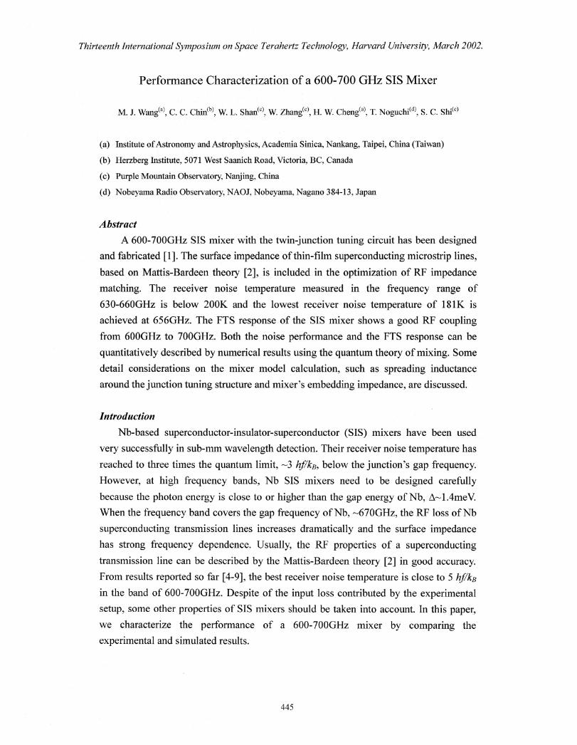
The embedding impedance of the 600-700GEL SIS mixer was calculated by HESS
using the structure of the SMA mixer block and RF choke, which are designed by the
receiver team at SAO, but with a substrate thickness of 30 m. Figure 1 shows the
calculated embedding impedance over the interesting frequency band. Both the real and
imaginary parts of the impedance vary remarkably in the band of 600-700GHz. This
variation of the embedding impedance should be considered in the mixer performance
calculation.
80
600a) 40
200.
0
U20-a2.40
-60400 460 500 660 600 660 700 760
Frequency (GHz)
Fig. 1 Embedding impedance of the 600-700GlIz SIS mixer calculated by BFSS.
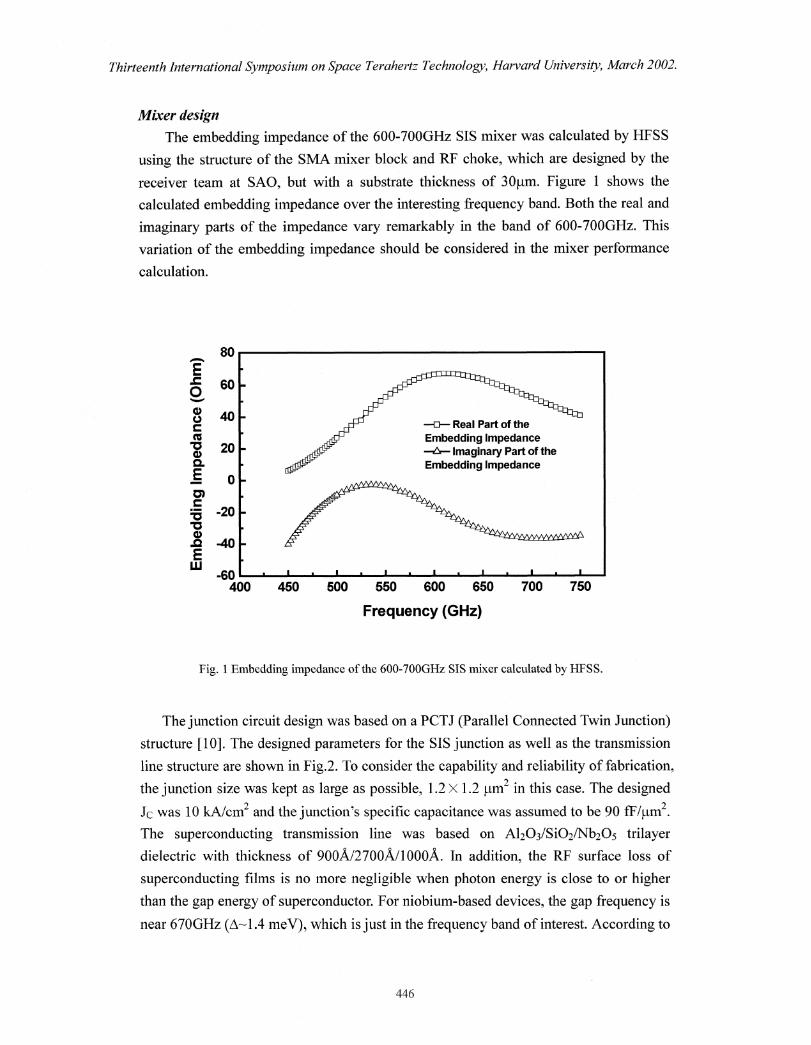
The junction circuit design was based on a PCTJ (Parallel Connected Twin Junction)
structure [10]. The designed parameters for the SIS junction as well as the transmission
line structure are shown in Fig.2. To consider the capability and reliability of fabrication,
the junction size was kept as large as possible, 1.2 X 1.2 1...tm 2 in this case. The designed
Jc was 10 kA/cm2 and the junction's specific capacitance was assumed to be 90 ffivirn2.
The superconducting transmission line was based on Al 203/Si02/Nb205 trilayer
dielectric with thickness of 900A/2700A/1000A. In addition, the RF surface loss of
superconducting films is no more negligible when photon energy is close to or higher
than the gap energy of superconductor. For niobium-based devices, the gap frequency is
near 670GHz (A-1 .4 meV), which is just in the frequency band of interest. According to
446
Je=101cA/cm2
A=1.2x1.2wn2
Ci=1.44m2 x 90fFilim2=129.6fF
Rn=13.540 (by Ielt1=1.95mV)
Thirteenth international Symposium on Space Terahertz Technology, Harvard University, March 2002.
Junction design parameters
Single Junction Parameters (design) Impedance transformer
1 2x .2 1, 2
Fig. 2 Designed SIS junction parameters and the transmission line structure near junction, in Inn unit.
The Jc is 10 kA/cm2 and the junction specific capacitance is assumed to be 90 fF/pm2 . Two 1.2 X 1.2 jAm2
junctions are connected by a 5.5pm wide superconducting transmission line to tune out the junction's
geometric capacitance.
Mattis-Bardeen theory [2], the RF losses of the superconducting transmission lines were
included during the optimization procedure of RF impedance matching [11]
Experiments
The SIS junction was fabricated by selective niobium etching process with
additional anodization technique [12]. The Nb/A10-A1Nb (1000A/70Al2000A)
multi-layer was in-situ deposited on crystal quartz wafer with RF choke photo-resist
lift-off pattern. The Al layer was exposed to 25 mtorr of Ar/10%0 2 mixture for 30
minutes to obtain critical current density (Jo) of 10I(A/cm 2 . The junction was defined by
Deep UV source of mask aligner and top Nb was etched by R1E system using CF4+02
mixture as processing gas. Before the deposition of the insulator layer, an additional
anodization process was applied to anodize about 300A thick Nb around the junction.
An insulating layer of SiOx/A10„ (2700A and 900A) was deposited as the dielectric of
the superconducting transmission lines. Before the deposition of a 6000A thick wiring
Nb film, the native oxide on top Nb surface was removed by applying Ar plasma. A
200A/2000A thick Ti/Au film was deposited on the contact pad of chip to reduce the
contact resistance of DC/IF leads. Then, the quartz substrate was thinned by lapping
machine and diced into individual chips, measuring 2mm (L) by 150inn (W) by 30jim
(T).
447
Hot/cold load
Mylar window
Metal grid
Thirteenth International Symposium on Space Terahertz Technology, Harvard University, March 2002.
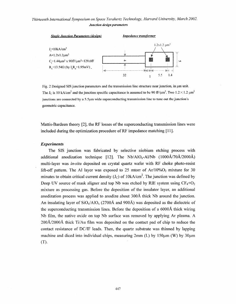
The mixer performance was measured in a liquid He cooled dewar using typical
hot/cold load technique. Fig. 3 shows the schematic drawing of the testing system. The
LO source was generated by a multiplier (doubler+triplier) pumped by Gunn oscillator.
Its frequency coverage is from 600GHz to 700GHz. The wire grid angle was set at 20'
to couple enough LO power. However, it will increase the input RF noise temperature.
Smaller grid angle was also tried to obtain lower receiver noise temperature in a narrow
frequency range limited by insufficient LO power. The RF signal and LO power passed
through a mylar vacuum window and Zitax IF filter, then were reflected by a cooled
off-axis parabolic mirror into the corrugated horn of the mixer block. The IF signal was
magnified by a cooled low noise amplifier (LNA) in the dewar and by a post amplifier
at room temperature, then detected by a 11P48xx power detector. Magnetic field by a
superconducting coil was applied to reduce the Josephson tunneling effect. The hot/cold
load was provided by a black body emitter at temperature of 295K177K. The FTS
measurement was done in the laboratory of National Astronomical Observatory of Japan
at Mitaka. To get more reliable information, we used the same mixer block and junction
in FTS and Trx measurement.
MirrorHEMT
Aà Room temperature
\ 4.2K plate
77K
Mixer blockDoubler / Tripler
.111■111■
WA/ Witx2 I x3 A
Gunn oscillator Teflon Lens
100GHz-116GHz
Fig. 3 Schematic drawing of the mixer performance testing system.
Results and discussion
IF post amplifier
IIF power meter
DC bias
IR filter
AAt E:=
448
5/i
6- 0
550
'Noe' 500
450
0414 :350
300
250
200
150
100
50
0 4
580 6()0 620 640 660 680 700 720
Frequency (GM)
Thirteenth International Symposium on Space Terahertz Technology, Harvard University, March 2002.
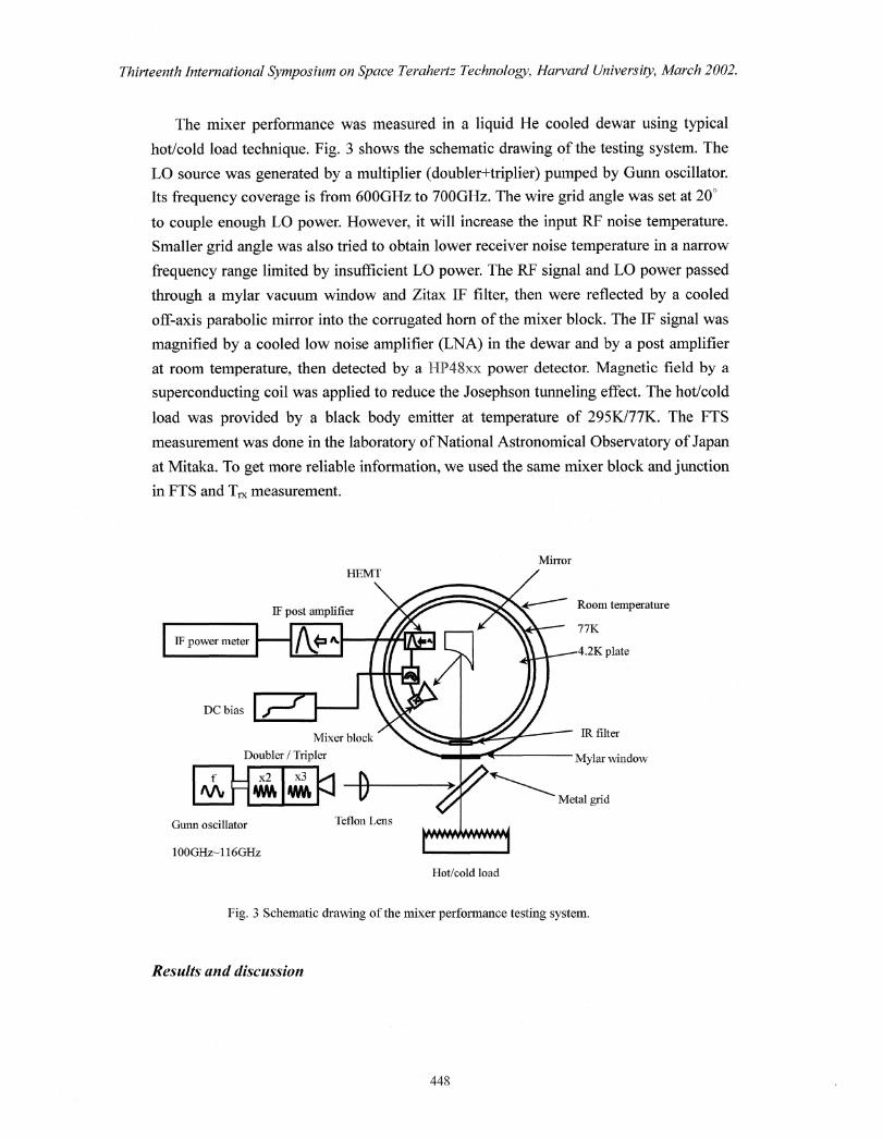
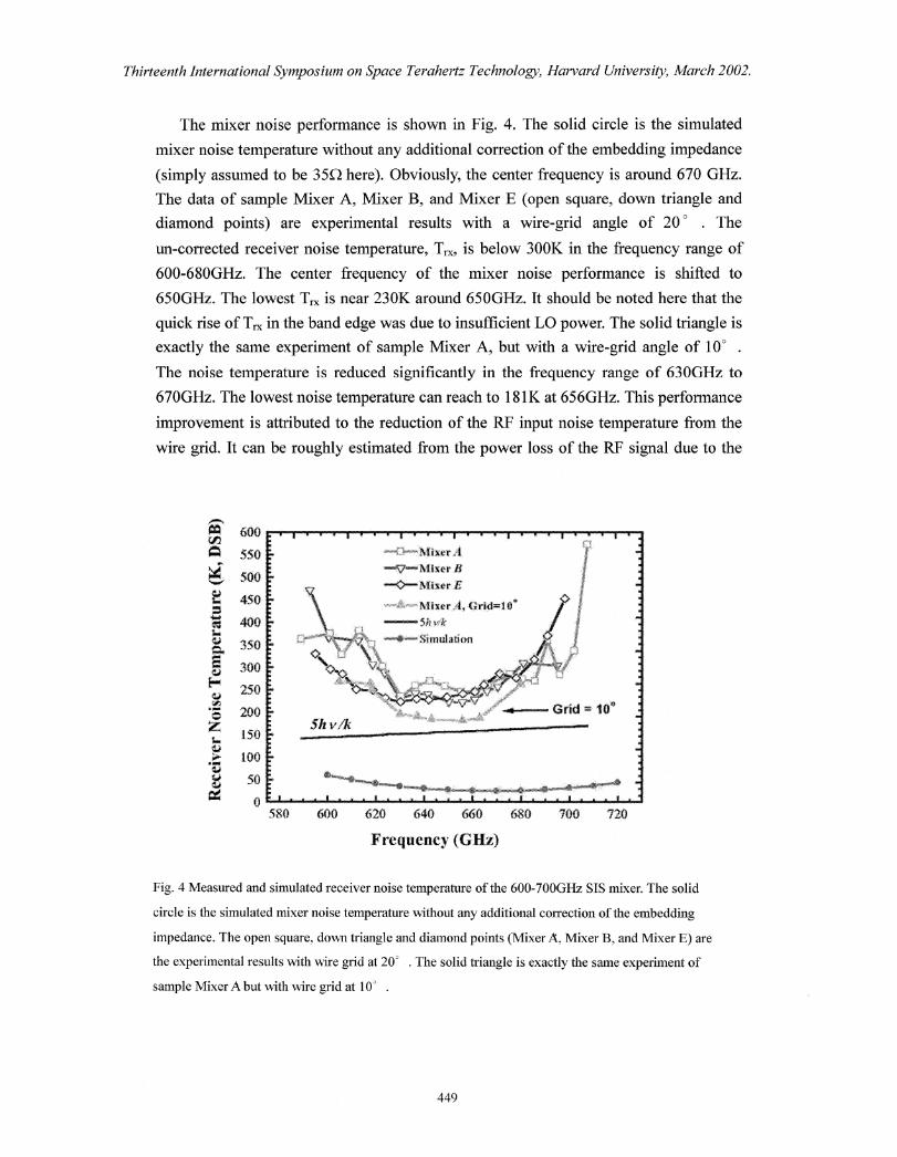
The mixer noise performance is shown in Fig. 4. The solid circle is the simulated
mixer noise temperature without any additional correction of the embedding impedance
(simply assumed to be 350 here). Obviously, the center frequency is around 670 GHz.
The data of sample Mixer A, Mixer B, and Mixer E (open square, down triangle and
diamond points) are experimental results with a wire-grid angle of 20 ° . The
un-corrected receiver noise temperature, T„, is below 300K in the frequency range of
600-680GHz. The center frequency of the mixer noise performance is shifted to
650GHz. The lowest T, is near 230K around 6500Hz. It should be noted here that the
quick rise of T, in the band edge was due to insufficient LO power. The solid triangle is
exactly the same experiment of sample Mixer A, but with a wire-grid angle of 10° .
The noise temperature is reduced significantly in the frequency range of 630GHz to
670GHz. The lowest noise temperature can reach to 181K at 656Gliz. This performance
improvement is attributed to the reduction of the RF input noise temperature from the
wire grid. It can be roughly estimated from the power loss of the RF signal due to the
Fig. 4 Measured and simulated receiver noise temperature of the 600-700GHz SIS mixer. The solid
circle is the simulated mixer noise temperature without any additional correction of the embedding
impedance. The open square, down triangle and diamond points (Mixer A, Mixer B, and Mixer E) are
the experimental results with wire grid at 20 . The solid triangle is exactly the same experiment of
sample Mixer A but with wire grid at 10' .
449
Thirteenth International Symposium on Space Terahertz Technology, Harvard University, March 2002.
misalignment between the waveguide polarization and the wire grid angle. The effective
angles of the wire grid projected onto the waveguide polarization direction are about
25.8' and 13.8' for setting at 20' and 10' on the grid's holder, respectively. It is
well known that the input noise of an object is equal to Tamb X a, where Tarim is the
physical temperature of object and a is the absorption coefficient. Thus, the input noise
temperature contributed from the wire grid is about 56K and 16K for the cases of the
wire grid set at 20' and HY on the grid's holder, respectively. The 40-K reduction of
T„, due to the wire grid angle changed from 20' to 10 , is consistent with the
experimental results.
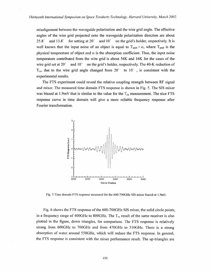
The FTS experiment could reveal the relative coupling strength between RIP signal
and mixer. The measured time domain FTS response is shown in Fig. 5. The SIS mixer
was biased at 1.9mV that is similar to the value for the T, x measurement. The nice FTS
response curve in time domain will give a more reliable frequency response after
Fourier transformation.
20000 •<, : OM 3SOCIO
Mirror Position
Fig. 5 Time domain FTS response measured for the 600-700GHz SIS mixer biased at 1.9mV.
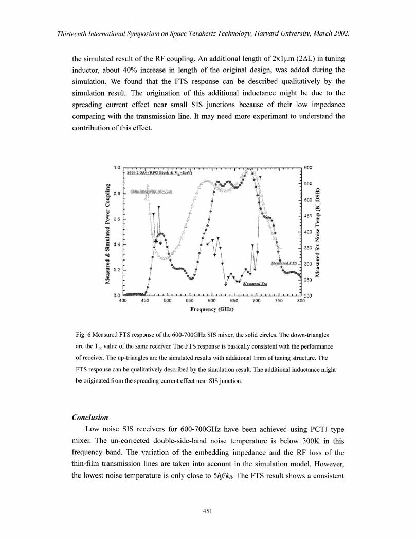
Fig. 6 shows the FTS response of the 600-700GHz SIS mixer, the solid circle points,
in a frequency range of 4000Hz to 800GHz. The T, result of the same receiver is also
plotted in the figure, down triangles, for comparison. The FTS response is relatively
strong from 600GHz to 700GHz and from 470GHz to 5 1 OGHz. There is a strong
absorption of water around 550GHz, which will reduce the FTS response. In general,
the FTS response is consistent with the mixer performance result. The up-triangles are
450
1.0
25
00.6
0.4
0,2ci*
200800•700 760
$660-2,3 iP,PG . Moat $4. 'filiigi.tvo:V)
medwrod rex
0.0400 460 500 650 800 660
Fre uent,7 (GM)
600
55
500
45
400
350
Thirteenth International Symposium on Space Terahertz Technology, Harvard University, March 2002.
the simulated result of the RF coupling. An additional length of 2x1p,m (2AL) in tuning
inductor, about 40% increase in length of the original design, was added during the
simulation. We found that the FTS response can be described qualitatively by the
simulation result. The origination of this additional inductance might be due to the
spreading current effect near small SIS junctions because of their low impedance
comparing with the transmission line. It may need more experiment to understand the
contribution of this effect.
Fig. 6 Measured FTS response of the 600-700GHz SIS mixer, the solid circles. The down-triangles
are the T, value of the same receiver The FTS response is basically consistent with the performance
of receiver. The up-triangles are the simulated results with additional lmm of tuning structure. The
FTS response can be qualitatively described by the simulation result. The additional inductance might
be originated from the spreading current effect near SIS junction.
Conclusion
Low noise SIS receivers for 600-700GHz have been achieved using PCTJ type
mixer. The un-corrected double-side-band noise temperature is below 300K in this
frequency band. The variation of the embedding impedance and the RF loss of the
thin-film transmission lines are taken into account in the simulation model. However,
the lowest noise temperature is only close to 5hf/kB. The FTS result shows a consistent
451
Thirteenth International Symposium on Space Terahertz Technology, Harvard University, March 2002.
frequency window of the RF coupling as Ti experiment. The simulated RF coupling
can qualitatively describe the FTS experimental result by adding an extra inductor. This
additional inductor might result from the current spreading effect near the SIS junctions.
More experimental results are necessary to clarify its origination.
Acknowledgement
We grateful appreciate the receiver team of SAO for providing the detail designs of
the mixer block and RF choke. We also thank Dr. Matsu° for his help on FTS
experiments and useful discussion.
References
[1] S.C. Shi, W.L. Shan, W Zhang, C.C. Chin, M.J. Wang, and T. Noguchi, "Development of a
600-720 GHz 'RS mixer for the SMART," in Proceedings of 12 th mt. Symp. on Space THz Tech,
San Diego, USA, Feb. 2001.
[2] D.C. Mattis and J. Bardeen, "Theory of the anomalous skin effect in normal and
superconducting materials," Phys. Rev., 111, 412, 1958.
[3] J. R. Tucker, IEEE J. Quantum Electron. QE-15, 1234, 1979.
[4] C.-Y. E. Tong, R. Blundell, D. C. Papa, J. W. Barrett, S. Paine, and X. Zhang, "A Fixed
Tuned Low Noise SIS Receiver for the 600 GHz Frequency Band, " The Proceedings of Sixth
International Symposium on Space Terahertz Technology, p. 295, 1995
[5] S. Hass, C. E. Honingh, D. Hottgenroth, K. Jacobs, and J. Stutzki, "Low noise broadband
Tunerless waveguide SIS Receivers for 440-500GHz and 630-690GHz, " International Journal
of Infrared and Millimeter Waves, 17(3), 493-506, 1996.
[6] C.-Y. E. Tong, R. Blundell, B. Bumble, J. A. Stem, and H. G. LeDuc, "Sub-millimeter
Distributed Quasiparticle Receiver Employing a Non-Linear Transmission Line, The
Proceedings of Seventh International Symposium on Space Terahertz Technology, p. 47, 1996.
[7] J. W. Kooi, M. S. Chan, H. G. LeDuc, and T. G. Phillips, "A 665GHz Waveguide Receiver
Using a Tuned 0.5 vim2 Nb/A10x/Nb SIS Tunnel Junction," The Proceedings of Seventh
International Symposium on Space Terahertz Technology, p. 76, 1996.
[8] T. Matsunaga, C.E. Tong, T. Noguchi, & R. Blundell, Proc. 12th Space THz Tech, Symp.,
San Diego, CA, (February 2001)
[9] accepted by International Journal of Infrared and Millimeter Waves, 2002.
[10] T. Noguchi, S. C. Shi, and J. Inatani, "An SIS Mixer Using Two Junctions Connected in
Parallel," IEEE Transaction on Applied Superconductivity, 5, p. 2228, 1995.
[11] S.C. Shi, C. C. Chin and W. Zhang, "Characterization of Nb-Based Superconducting
Transmission Lines around the Gap Frequency," International Journal of Infrared and
Millimeter Waves 21(12): 2007-2013; Dec 2000
[12] T. Noguchi, A. Sakamoto, S. Ochiai, "Fabrication of sub-micron SI'S junctions," Technical
Report of lEICE, SCE93-64, pp.43-48, 1994.
452