
PERFORMANCE ANALYSIS OF MICRO GAS … ANALYSIS OF MICRO GAS TURBINE DRIVEN THROUGH...
11
34 PERFORMANCE ANALYSIS OF MICRO GAS TURBINE DRIVEN THROUGH COMPRESSION- ABSORPTION REFRIGERATION SYSTEMS Upendra Kumar 1 and Amit Kumar 1 * *Corresponding Author: Amit Kumar, [email protected] The paper analyses configuration of combined refrigeration system consisting of a compression chiller and an absorption chiller that is driven by a micro turbine to generate cooling at low temperatures. The compression chiller is operated directly by the micro turbine at the low temperature stage and the waste heat from the micro turbine is used to drive the absorption chiller that operates at the high temperature stage and helps to the compression chiller performance. From the results obtained, it is concluded that the use of this configuration of integrated refrigeration system is more efficient and less energy consuming than the system without absorption chiller. Keywords: Micro gas turbine, Combined refrigeration system, Absorption, Compression, Performance INTRODUCTION The accelerated need for new energy generation systems and distribution lines to cope with the increase in electricity demands in recent years is causing supply problems and high emissions of pollutants. Cooling demand is increasing dramatically, and peak demand for power in several countries now is in summer, not winter. Combined Heat and Power (CHP) is the simultaneous generation of heat and power in a single process. Combined heat and power applications will ISSN 2278 – 0149 www.ijmerr.com Vol. 2, No. 3, July 2013 © 2013 IJMERR. All Rights Reserved Int. J. Mech. Eng. & Rob. Res. 2013 1 Department of Mechanical Engineering, National Institute of Technology Patna 800005, Bihar, India. contribute significantly to reduction of CO 2 emissions due to their higher global efficiency in comparison to conventional power stations. The use of CHP systems in refrigeration application would bring several advantages such as enhancement in power since the system can be operated independent of the grid and saving energy. Another important benefit is the security of supply. Herold et al. (1991) have analysed Hybrid refrigeration cycles which combine a mechanical compressor and an absorption cycle in such Research Paper
Transcript of PERFORMANCE ANALYSIS OF MICRO GAS … ANALYSIS OF MICRO GAS TURBINE DRIVEN THROUGH...

34
Int. J. Mech. Eng. & Rob. Res. 2013 Upendra Kumar and Amit Kumar, 2013
PERFORMANCE ANALYSIS OF MICRO GASTURBINE DRIVEN THROUGH COMPRESSION-
ABSORPTION REFRIGERATION SYSTEMS
Upendra Kumar1 and Amit Kumar1*
*Corresponding Author: Amit Kumar,[email protected]
The paper analyses configuration of combined refrigeration system consisting of a compressionchiller and an absorption chiller that is driven by a micro turbine to generate cooling at lowtemperatures. The compression chiller is operated directly by the micro turbine at the lowtemperature stage and the waste heat from the micro turbine is used to drive the absorptionchiller that operates at the high temperature stage and helps to the compression chillerperformance. From the results obtained, it is concluded that the use of this configuration ofintegrated refrigeration system is more efficient and less energy consuming than the systemwithout absorption chiller.
Keywords: Micro gas turbine, Combined refrigeration system, Absorption, Compression,Performance
INTRODUCTIONThe accelerated need for new energygeneration systems and distribution lines tocope with the increase in electricity demandsin recent years is causing supply problems andhigh emissions of pollutants. Cooling demandis increasing dramatically, and peak demandfor power in several countries now is insummer, not winter. Combined Heat andPower (CHP) is the simultaneous generationof heat and power in a single process.Combined heat and power applications will
ISSN 2278 – 0149 www.ijmerr.comVol. 2, No. 3, July 2013
© 2013 IJMERR. All Rights Reserved
Int. J. Mech. Eng. & Rob. Res. 2013
1 Department of Mechanical Engineering, National Institute of Technology Patna 800005, Bihar, India.
contribute significantly to reduction of CO2
emissions due to their higher global efficiencyin comparison to conventional power stations.The use of CHP systems in refrigerationapplication would bring several advantagessuch as enhancement in power since thesystem can be operated independent of thegrid and saving energy. Another importantbenefit is the security of supply. Herold et al.(1991) have analysed Hybrid refrigerationcycles which combine a mechanicalcompressor and an absorption cycle in such
Research Paper

35
Int. J. Mech. Eng. & Rob. Res. 2013 Upendra Kumar and Amit Kumar, 2013
way that they share a single evaporator. Theyhave shown that the cycle have significantpotential from a thermodynamic viewpoint. Hoet al. (2004) have presented a micro turbineco-generation system that provides electricalpower and space cooling to a laboratoryspace. They studied the performance of theco-generation system under varying heat loadin the cooling space and longer micro turbineoperating period. Bruno et al. (2009) havestudied the performance of gas micro turbinesof different power capacities directly coupledto double effect water/LiBr absorption chillers.In these systems post-combustion natural gashave been used to increase the coolingcapacity of the system. [4] Fernandez-Searaet al. (2006) analyzed an alternativerefrigeration system that could reduce theelectricity consumption in those applications.This system consists of a compression systemat low temperature stage and an absorptionsystem at high temperature stage. Also theystudied the possibility of powering this systemby means of a co-generation system.Cogeneration is synonyms with CHP. In hybridrefrigeration systems CHP can supplysimultaneously the power to the compressionsystem and the heat to the absorption system.Bruno et al. (2005) analysed variousintegrated configurations of several types ofcommercially available absorption coolingchillers and MGT cogeneration systems drivenby bio-gas. MGTs are fuelled with biogas andtheir waste heat is used to drive absorptionchillers and other thermal energy users. Thechillers considered in this study include single-and double-effect water/LiBr and ammonia/water chillers. The exhaust gas from the MGTcan be used directly to drive the chiller or
indirectly to produce hot water to drive thechiller. He conducted a case study for anexisting sewage treatment plant. Chilled wateris used to reduce humidity in the bio-gas pre-treatment process and cool the combustion airof the MGT. He identified the most interestingintegrated configurations for tri-generationsystems that use bio-gas and micro gasturbines. He analysed these configurationsand compared them with conventionalconfigurations using operational data from anexisting sewage treatment plant. The bestconfigurations are those that completelyreplace the existing system with a tri-generation plant that uses all the availablebiogas and additional natural gas tocompletely meet the heating demands of thesewage treatment plant. Garimella et al. (2011)has conceptualized and analyzed a novelcascaded absorption/vapour-compressioncycle with a high temperature lift for a navalship application. Also they compared theperformance of this system with an equivalenttwo-stage vapour-compression cycle. In thepresent study, configuration of a refrigerationsystem that integrated with a micro turbine andan absorption chiller to generate cooling at lowtemperatures are analyzed. The electricityproduced by the micro turbine used to drivethe compression chiller and the heat recoveredfrom the micro turbine is used in the absorptionchiller. Overall efficiency of this configurationis compared to a system that is operatingwithout any waste heat utilization andconsisting of a micro turbine and acompression chiller. The main components ofthe proposed system are micro gas turbine,vapour-compression chiller and water/LiBrabsorption chiller.

36
Int. J. Mech. Eng. & Rob. Res. 2013 Upendra Kumar and Amit Kumar, 2013
DESCRIPTION OF THE MAINSUBSYSTEMSThe main parts of proposed system are microgas turbine, Vapour-compression chiller andwater/LiBr absorption chiller.
Micro Gas Turbine
Micro turbines are small, compact high-speedturbo-generators of 28 to 200 KW, whichconsist of a centrifugal compressor, a radialturbine and a permanent magnet alternatorrotor operating as a Brayton cycle. Their mainfeatures are that the high-speed generator isdirectly coupled to the turbine rotor and thatthey use power electronics instead of agearbox and conventional generator to adaptthe power produced to the grid power quality.
In a typical MGT re-generative system, theincoming atmospheric air is first filtered andused as a cooling medium for the alternatorand electronic devices. The air leaving thealternator is later compressed and passedthrough the regenerator, where it is preheatedwith the hot gases leaving the turbine before it
enters the combustion chamber. This reducesthe amount of fuel used to reach the operatingtemperature. In the combustion chambercompressed fuel is burned with excesscompressed air to produce hot gas at hightemperature and pressure. This is thenexpanded through the turbine, which extractsenergy and uses it to drive the compressor andthe alternator. The turbine exhaust gas is fedthrough the regenerator and can then be fedto a boiler, a directly driven absorption chiller,a desiccant cooling system, or any otherprocess that can benefit from high gasestemperature. The main advantages that MGTshave over other technologies are the fuelflexibility, low emissions, quiet operation andlow maintenance. The electrical efficiency ofthe current re-generative MGTs is in the rangeof 25-30% depending on the MGT size.However, the micro turbine efficiency dependson the ambient temperature. As the ambienttemperature increases, the efficiency and thepower of micro turbine both decrease (Figure1). This is mainly because the air density at
Figure 1: Performance of Micro Turbine vs. Ambient Temperature
Source: Hwang (2004)

37
Int. J. Mech. Eng. & Rob. Res. 2013 Upendra Kumar and Amit Kumar, 2013
high air temperature is lower and, for the sameinlet volume of air, a lower mass of fluidcirculates the system. It should be noted thatthis performance dependence on the ambienttemperature and might be changed through adifferent design approach.
The power from the micro turbine is appliedto the compression chiller compressor, thefans of the system and to the absorption chillerpump. To recover the waste heat from the microgas turbine an exhaust gas heat exchangerproduce hot water to drive the absorptionchiller (Figure 2). It was assumed that 42% ofthe fuel energy from the micro turbine exhaustgas is delivered to the absorption chiller.
Absorption Chiller
Absorption chillers are thermally driven chillersthat are well suited for the use of exhaust heatfrom prime movers such as micro turbines.There are various types of absorption cycles.They can be single effect, double effect or triple
effect and can be powered by hot water, steamor combustion gases. Two preferredrefrigerant and absorbent pairs in theabsorption cycles are water/LiBr andAmmonia/water. Ammonia/water systemrequires higher generator inlet temperaturesthan water/LiBr system and higher pressuresand hence higher pumping power.
It also requires a separation system toseparate ammonia from water at the generatoroutlet but the water/LiBr chiller do not requireany separation system. Though water/LiBrsystem has a limited range of operation,because of the crystallization, but the low costand excellent performance of this working fluidcombinations make it favourable for use. In thepresent study, single effect, hot water drivenwater/LiBr absorption chillers are considered.The model equations are formulated frommass and energy balances for eachcomponent of absorption cycle. The following
Figure 2: Energy Flow in Combined System

38
Int. J. Mech. Eng. & Rob. Res. 2013 Upendra Kumar and Amit Kumar, 2013
assumptions have been made during thepresent study:
• Refrigerant in the evaporator and condenseris pure water.
• Stream coming out from the condenser issaturated water, and the condenserpressure is the saturated pressure atcondenser temperature.
• Saturated vapour leaves the evaporator andthe evaporator pressure is the saturatedpressure at evaporator temperature.
• The efficiency of the pump is 50%.
• Air cooled condenser and absorber areused. Condensing temperature andabsorbent temperature are 10 °C higherthan air temperature.
• The generator temperature is assumed as90 °C at the ambient temperature of 30 °C.
• The evaporator temperature is assumed as5 K at the ambient temperature of 30 °C.
• The power input to the condenser andabsorber fan motor is 775 W for 1 cubemetre per second air flow rate and the airflow rate through these components is0.0537 metre cube per second for 1 KWheat transfer.
• The solution concentration at the outlet ofthe absorber is the equilibriumconcentration to the absorber temperature.
• The solution concentration at the outlet ofthe generator is the equilibriumconcentration to the generator temperature.
Compression Chiller
The compression chillers in this study is similarto conventional vapour-compression chillersand includes compressor, condenser,
evaporator and expansion valve and using R22as its working fluid. The model equations aresimilar to absorption cycle, formulated frommass and energy balances. The followingassumptions based on Hwang (2004) areused in this model:
• Evaporation temperature was considered10 K lower than the refrigerated airtemperature.
• Condensing temperature was considered10 K higher than air temperature.
• Degree of superheating at evaporator outletis 5 K and the water exiting the condenseris 5 K sub cooled.
• Pressure drop at evaporator and condenseris 50 kPa.
• Compressor isentropic efficiency dependsupon the pressure ratio.
• The same assumptions used for the fans ofabsorption chiller are applied in theevaporator and condenser fan motors.
ANALYSISThe configuration of the integrated refrigerationsystem is analyzed to generate cooling at lowtemperatures and is compared for their energyefficiency to the base system. The basesystem is a system without absorption chillerand it consists of a compression chiller and amicro gas turbine. In the analyzed system theuse of absorption chiller improves the overallsystem efficiency by reducing the electricityconsumption in the compression chiller.
Performance of the Base System
The base system is used for reference andconsists of a compression chiller and a microgas turbine. In this case, the waste heat from

39
Int. J. Mech. Eng. & Rob. Res. 2013 Upendra Kumar and Amit Kumar, 2013
micro gas turbine is released to theatmosphere.
Performance of the Configuration
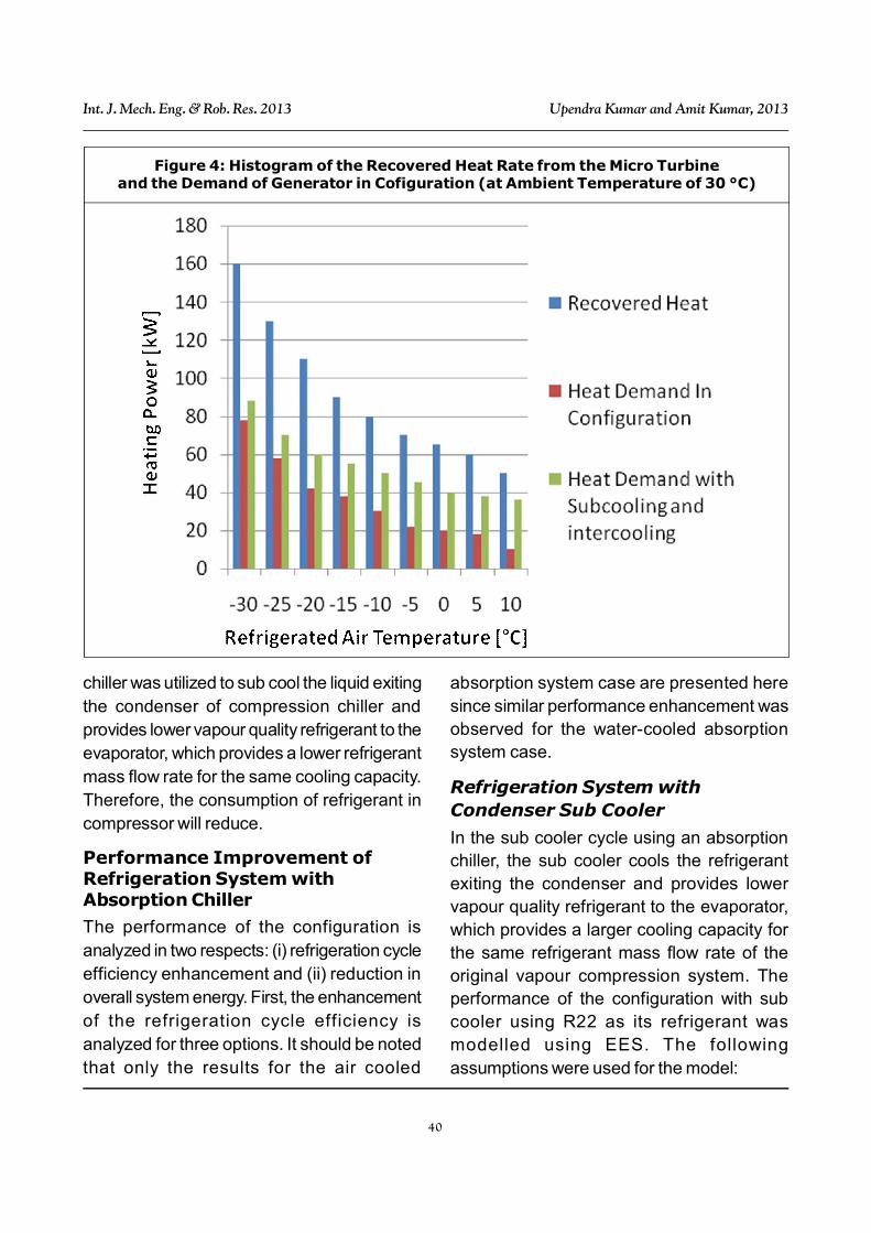
In this configuration the absorption chilleroperates at the high temperature stage andthe compression chiller operates at the lowtemperature stage. A micro gas turbinesupplies simultaneously the electricity to thesystem and the heat to the absorption chiller(Figure 3). If the power generated by microturbine is equated to the power required bythe system, the heat demand for the generatorof absorption chiller is higher than the wasteheat recovered from the micro turbine. Figure4 shows the amounts of heat demand and thewaste heat recovered at various refrigeratedair temperatures. As refrigerated airtemperature increases, the heat demanddecreases by 50%, while the waste heat
recovered decreases by 215%. It means thatat higher refrigerated air temperatures, theheat demand is much higher than the wasteheat recovered and extra heat is needed.There is a two stage compression chiller withan intercooler between two compressors ofcompression chiller in the configuration. Intercooling between two stages of compressionchiller reduces the work of compression perkilogram of vapour. The absorption chillerprovides inter cooling. The compression chillerrefrigerant and the water in evaporator ofabsorption chiller exchange heat in counterflow configuration. The higher amount of theheat recovered by micro turbine is used in theabsorption chiller and the surplus cooling isemployed to sub cool the liquid exiting thecondenser of compression chiller, so thereduction in the work of compressionincreases. The cooling capacity of absorption
Figure 3: Schematic Diagram of Configuration
40
Int. J. Mech. Eng. & Rob. Res. 2013 Upendra Kumar and Amit Kumar, 2013
chiller was utilized to sub cool the liquid exitingthe condenser of compression chiller andprovides lower vapour quality refrigerant to theevaporator, which provides a lower refrigerantmass flow rate for the same cooling capacity.Therefore, the consumption of refrigerant incompressor will reduce.
Performance Improvement ofRefrigeration System withAbsorption Chiller
The performance of the configuration isanalyzed in two respects: (i) refrigeration cycleefficiency enhancement and (ii) reduction inoverall system energy. First, the enhancementof the refrigeration cycle efficiency isanalyzed for three options. It should be notedthat only the results for the air cooled
absorption system case are presented heresince similar performance enhancement wasobserved for the water-cooled absorptionsystem case.
Refrigeration System withCondenser Sub Cooler
In the sub cooler cycle using an absorptionchiller, the sub cooler cools the refrigerantexiting the condenser and provides lowervapour quality refrigerant to the evaporator,which provides a larger cooling capacity forthe same refrigerant mass flow rate of theoriginal vapour compression system. Theperformance of the configuration with subcooler using R22 as its refrigerant wasmodelled using EES. The followingassumptions were used for the model:
Figure 4: Histogram of the Recovered Heat Rate from the Micro Turbineand the Demand of Generator in Cofiguration (at Ambient Temperature of 30 °C)

41
Int. J. Mech. Eng. & Rob. Res. 2013 Upendra Kumar and Amit Kumar, 2013
Evaporator
• Refrigeration capacity is 100 kW.Refrigerant mass flow rate is adjusted foreach case.
• Evaporation temperature is 10 K lower thanthe refrigerated air temperature.
• Superheat of vapour is 5 K exiting theevaporator.
• Pressure drop is 50 kPa.
Condenser
• Condensing temperature is 10 K higherthan the inlet air temperature.
• Degree of sub cooling at condenser outletis 5 K.
• Pressure drop is 50 kPa.
Compressor
• Isentropic and volumetric efficiencieschange depending upon the Pressure Ratio(PR).
Sub Cooler
• H2O/LiBr absorption chillers provide the
additional sub cooling.
• Absorption chiller works only for an ambienttemperature between 7.2 and 40.6 °C.
• The sub cooled liquid refrigerant and chilledwater exchange heat in counter flowconfiguration. The approach temperature is2 K.
• The approach temperature limits thedegree of sub cooling.
• The sub cooler does not affect the pressuresof the evaporator and condenser.
• When the air-cooled absorption chiller isused, the evaporating temperature of the
absorption chiller is controlled dynamicallyaccording to the ambient temperature whenthe water-cooled absorption chiller is used;the evaporating temperature is maintainedat 38 °C of the ambient temperature.
Motor
• Air flow rate through the evaporator is0.0537 m3/s for 1 kW refrigeration capacity.
• Power input to the evaporator andcondenser fan motor is 775 W for 1 m3/sairflow rate.
• Evaporator motor is located in the cold airstream and works as thermal load.
Refrigeration System with SubCooler and Micro Turbine IntakeAir Pre Cooler
Since the utilization of the sub cooling capacityfrom the sub cooler is limited, the surpluscooling capacity by the sub cooler can beemployed to pre-cool the intake air enteringthe micro turbine. The surplus cooling capacityand the amount of the cooling capacity usedto pre cool the micro turbine intake air arecompared to the sub cooling capacityavailable from the sub cooler. If this surpluscooling is utilized to pre cool the intake airentering the micro turbine, the micro turbineefficiency can be improved. For example, themicro turbine efficiency improvement is 13%if all the surplus cooling capacity is used at40.6 °C. However, heat transfer limits theutilization of the surplus cooling in most casesbecause the intake air temperature cannot belower than the sub cooler temperature. Toaccount for this heat transfer limitation, theambient air temperature was assumed to behigher than that of the sub cooler temperatureby 2 K. The cooling capacity used to pre cool

42
Int. J. Mech. Eng. & Rob. Res. 2013 Upendra Kumar and Amit Kumar, 2013
the intake air increases as the ambienttemperature increases but its utilization isclearly limited especially at low ambienttemperature. This heat transfer limitationresults in the limitation of the micro turbineefficiency improvement. Moreover, it meansthat the current waste heat recovery is largeenough and more waste heat recovery can notcontribute to the further enhancement.
Refrigeration System withCondenser Air Pre Cooler
In the pre cooler cycle using an absorptionchiller, the pre cooler cools the air entering thecondenser and supplies the air at reducedtemperature. The lower air temperatureentering the condenser results in a lowerpressure ratio and reduced compressor powerconsumption. The same assumptions used forthe evaporator, condenser and compressor ofthe cycle with sub cooler were applied in themodel. The following assumptions for the precooler were used in addition to the previousassumptions:
Pre Cooler
• Airflow rate is the same as that of theconventional cycle to increase the airtemperature by 5 K across the condenser.
• LiBr absorption chiller provides the precooling.
• Absorption chiller works only for ambienttemperature between 7.2 and 40.6 °C.
• Pre cooler does not affect the evaporationpressure.
• Refrigerant and air heat exchange occursin cross counter flow configuration. Theapproach temperature is 2 K.
• The same assumption for the evaporatingtemperature of the absorption chiller usedfor the sub cooler cycle is used.
The Effect of AmbientTemperature
The effect of ambient temperature on systemperformance was also investigated over therange 10-40 °C. In absorption chillers, if thesolution concentration is too high or thesolution temperature is reduced too low,crystallization may occur and interrupt systemoperation. As the ambient temperaturedecreases, the generator temperature must bedecreased to avoid of crystallizing. At lowambient temperatures, overall efficiency canbe increased by decreasing temperature ofthe absorption chiller evaporator. Also atambient temperatures higher than 30 °C, bygenerator temperature of 90 °C, the generatorcouldn’t disrobe lithium Bromide from waterdue to the high concentration of the enteringsolution to the generator. By increasing theambient temperature, the temperature ofgenerator and evaporator in absorption chillerhas been changed to solve this obstacle andalso to have optimum efficiency. Thesechanges of operating temperatures of
Table 1: Temperature of Generator and Evaporator of Absorption Chillervs. Ambient Temperature
Ambient Temperature in °C 10 15 20 25 30 35 40
Evaporating Temperature in °C 2 2 2 2 5 8 14
Generating Temperature in °C 65 75 80 85 90 95 100

43
Int. J. Mech. Eng. & Rob. Res. 2013 Upendra Kumar and Amit Kumar, 2013
generator and evaporator in this study arepresented in Table 1.
CONCLUSION• Micro turbines have emerged as one of new
on-site power generation technologies toprovide a reliable power supply against theincreasingly susceptible electric grid.
• The overall energy efficiency of the systemusing micro turbines as its power supply canbe improved, if the waste heat from microturbines is recovered by an absorptionchiller.
• The results show that the use of absorptionchillers to assist the compression chillersto generate low temperatures (lower than0 °C), can reduce energy consumption.
• A refrigeration system with condenserevaporator heat exchanger and auxiliaryboiler, with condenser evaporator heatexchanger and a conventional compressionchiller that works under integrated systemcondition with intercooler between twocompressors, and with intercooler and subcooler can reduce energy consumption byas much as 133%, compared to the systemwithout any waste heat utilization from themicro turbine.
• The integrated system with thisconfiguration can operate at hightemperatures as much as 40 °C, while withincreasing the ambient temperature, thetemperature of absorption chillersevaporator and generator increase.
• To operate this system at ambienttemperatures lower than 30 °C, thetemperature of absorption chiller generatormust be decreased to prevent crystallization.
• The energy consumption of a refrigeration
system with condenser evaporator, heatexchanger and auxiliary boiler has highefficiency to generate cooling at lowtemperature but the energy consumption ofthis system at low ambient temperaturesand at high refrigerated air temperatures,
is higher than the system without absorptionchiller.
REFERENCES1. Bruno J C, Ortega-Lopez V and Coronas
A (2009), “Integration of AbsorptionCooling Systems into Micro Gas TurbineTri Generation Systems Using Biogas:Case Study of a Sewage TreatmentPlant”, Appl. Energy, Vol. 86, pp. 837-847.
2. Bruno J C, Valero A and Coronas A(2005), “Performance Analysis ofCombined Micro Gas Turbines and Gas
Fired Water/LiBr Absorption Chillers withPost-Combustion”, Appl. Therm. Eng.,Vol. 25, pp. 87-99.
3. Fernandez-Seara J, Sieres J andVazquez M (2006), “Compression-Absorption Cascade RefrigerationSystem”, Appl. Therm. Eng., Vol. 26,pp. 502-512.
4. Garimella S, Brown A M, Krishna A andNagavarapu A K (2011), “Waste HeatDriven Absorption/Vapour-CompressionCascade Refrigeration System for
Megawatt Scale, High-Flux, LowTemperature Cooling”, Int. J.Refrigeration, Vol. 34, pp. 1776-1785.
5. Herold K E, Howe L A and RadermacherR (1991), “Analysis of a Hybrid

44
Int. J. Mech. Eng. & Rob. Res. 2013 Upendra Kumar and Amit Kumar, 2013
Compression-Absorption Cycle UsingLithium Bromide and Water as theWorking Fluid”, Int. J. Refrigeration,Vol. 14, pp. 264-272.
6. Ho J C, Chua K J and Chou S K (2004),“Performance Study of a Micro TurbineSystem for Cogeneration Application”,Renew. Energy, Vol. 29, pp. 1121-1133.


