
PEPPE CABLE GLAND - CSL Online · with Marine Shipboard & Tray Cables under NEC ... LSOH cables and...
11
PEPPERS CABLE GLANDS www.cableglands.com
Transcript of PEPPE CABLE GLAND - CSL Online · with Marine Shipboard & Tray Cables under NEC ... LSOH cables and...

PEPPERS CABLE GLANDS
www.cableglands.com

MORE THAN THE SUM OF OUR PARTS,
,
A
l
.
unit
www.cableglands.com
minimises the possibility of occuring during installation and deluge protection is achieved without the use of additional sealing devices.
B G
our competitors designs allowing the use of
smaller
A R S P B D
t
, ISO/IEC 80079-34:2011 Explosive atmospheres -- Part 34: Application of quality systems for equipment manufacture and an
as well as operating within Occupational Health and Safety Management (OHS) to BS OHSAS 18001.
www.cableglands.com
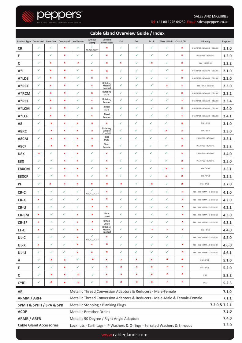
Product T pe Outer Seal Co pou d Co duit
Connection E d E e E R Class Di II Class Di I IP Rati g Page No.
CR CROCLOCK ®
IP66 / IP68 - NEMA 4X - DELUGE . .
E
IP66 / IP68 - NEMA 4X . .
C
IP66 - NEMA 4X .2.2
A*L IP66 / IP68 - NEMA 4X - DELUGE . .
A*LDS IP66 / IP68 - NEMA 4X - DELUGE . .
A*RCC IP66 / IP68 - DELUGE . .
A*RCM RotatingMale IP66 / IP68 - NEMA 4X - DELUGE . .2
A*RCF RotatingFemale IP66 / IP68 - NEMA 4X - DELUGE . .4
A*LCM IP66 / IP68 - NEMA 4X - DELUGE . .
A*LCF IP66 / IP68 - NEMA 4X - DELUGE . .
A IP66 - IP68 . .
A RC IP66 - IP68 .3.
A CM IP66 / IP68 - NEMA 4X . .1
A CF IP66 / IP68 - NEMA 4X . .2
D X IP66 / IP68 - NEMA 4X . .
E X IP66 / IP68 - NEMA 4X . .
E XCM IP66 / IP68 .5.1
E XCF IP66 / IP68 .5.2
PF IP66 - IP68 . .
CR‐C IP66 - IP68 NEMA 4X - DELUGE . .
CR‐X IP66 - IP68 NEMA 4X - DELUGE . .
CR‐U IP66 - IP68 NEMA 4X - DELUGE . .
CR‐SM IP66 - IP68 NEMA 4X - DELUGE . .
CR‐SF IP66 - IP68 NEMA 4X - DELUGE . .
LT‐C IP66 - IP68 . .
UL‐C IP66 - IP68 NEMA 4X - DELUGE . .
UL‐X IP66 - IP68 NEMA 4X - DELUGE . .
UL‐U IP66 - IP68 NEMA 4X - DELUGE . .
A
IP66 - IP68 . .
E
IP66 - IP68 . .
C
IP66 .2.2
C*IE IP66 .2.3
Ca le Gla d O er ie Guide / I deInner Seal
ArmourClampLead Option
FixedMale
CROCLOCK ®
CROCLOCK ®
RotatingMetallicConduit
FixedFemale
RotatingMetallicConduit
FixedMale
FixedFemale
RotatingMetallicConduit
MaleUnion
FemaleUnion
SALES AND ENQUIRIESTel: +44 (0) 1276 64232 Email: [email protected]
AR 7.1.0Metallic Thread Conversion Adaptors & Reducers - Male-FemaleARMM / ARFF 7.1.1Metallic Thread Conversion Adaptors & Reducers - Male-Male & Female-Female
7.2.0 & 7.2.1SPMH & SPHH / SPA & SPB 7.3.0ACDP7.4.0ARMR / ARFR
Metallic Breather Drains
Metallic 90 Degree / Right Angle Adaptors
www.cableglands.com
Metallic Stopping / Blanking Plugs
7.5.0Cable Gland Accessories Locknuts - Earthtags - IP Washers & O-rings - Serrated Washers & Shrouds
Notes:
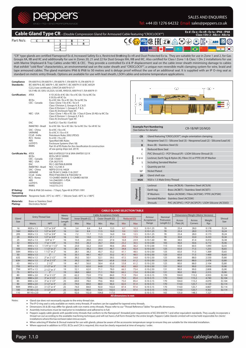
Cable Gland Type CR - (Double Compression Gland for Armoured Cable featuring “CROCLOCK®”)
C R 1 B *2 S R34
Part No’s:
“CR” type glands are certified Flameproof Ex d, Increased Safety Ex e, Restricted Brea thing Ex nR and Dust Protected Ex ta. They are suitable for use in Zone 1 and 2, for Gas Groups IIA, IIB and IIC and additionally for use in Zones 20, 21 and 22 for Dust Groups IIIA, IIIB and IIIC. Also certified for Class I Zone 1 & Class 1 Div 2 installations for use with Marine Shipboard & Tray Cables under NEC & CEC. They provide a controlled Ex d & IP displacement seal on the cable inner sheath minimising damage to cables that exhibit “cold flow” characteristics, an environmental seal on the outer sheath and “CROCLOCK®”, a unique non reversible multi clamping system for wire, braid and tape armoured cables. The gland maintains IP66 & IP68 to 50 metres and is deluge proof without the use of an additional seal. It is supplied with an IP O- ring seal as standard on metric entry threads. Options are available for use with lead sheath, LSOH cables and extreme temperature applications.
Compliance
Standards:
EN 60079-0, EN 60079-1, EN 60079-7, EN 60079-15, EN 60079-31
IEC 60079-0, IEC 60079-1, IEC 60079-7, IEC 60079-31 & IEC 60529
C22.2 (see certiicate), CAN/CSA 60079-0/1/7
UL514B, UL1203, UL2225, UL50E, ANSI/UL 60079-0/7, ISA 60079-31
Certiication: ATEX II 1D 2G Ex d IIC Gb / Ex e IIC Gb / Ex ta IIIC DaII 3G Ex nR IIC Gc
IECEx Ex d IIC Gb / Ex e IIC Gb / Ex ta IIIC DaCEC - Canada Class I Zone 1 Ex d IIC / Ex e II
Class I Division 2, Groups A, B, C & DClass II Division 1, Groups E, F & GClass III, Enclosure Type 4X
NEC - USA Class I Zone 1 AEx e IIC Gb / Class II Zone 20 AEx ta IIIC DaClass II Division 1, Groups E, F & G Class III, Enclosure Type 4X
EAC Exd IICU / Exe IIU / ExnR IIU
INMETRO - Brazil Ex d IIC Gb / Ex e IIC Gb / Ex ta IIIC Da / Ex nR IIC Gc
SAC - ChinaUKRAINECCoE - IndiaKCS - KoreaABSLLOYD’SRMRS
Certiicate No. ATEXIECExCEC - CanadaNEC - USAEAC
Ex d IIC / Ex e IICEx d IIC X / Ex e II XPetroleum Rules 2002 (PESO)Ex d IIC / Ex e IICSpeciied ABS RulesEnclosure Systems (Part 1B)Part XI of RS Rules for the classiication & construction of sea-going ships (ed. 2014)
BAS 01ATEX2271X & SIRA 09ATEX1221XIECEx SIR 07.0099XCSA 1356011CSA 2627370RU C-GB.ГБ06.В.00098
INMETRO - Brazil NCC 13.2185 XSAC - ChinaUKRAINECCoE - IndiaKCS - KoreaABSLLOYD’SRMRS
NEPSI GYJ16.1402XUA.TR.047.C.0408-13 & 2937PESO P365300/2 & P365300/1415-GA4BO-0669X & 15-GA4BO-0670X14-LD463991-1-PDA10/00056(E1)14.02755.315
IP Rating: IP66 & IP68 (50 metres - 7 Days), Type 4X & DTS01:1991OperatingTemperature: Neoprene Seals -35°C to +90°C / Silicone Seals -60°C to +180°C
Materials: Brass or Stainless SteelPlating: Electroless Nickel
Example Part Numbering
(See below for details)CR-1B/NP/20/M20
CR Gland featuring “CROCLOCK®”, single orientation clamping
1 Neoprene Seal (1) - Silicone Seal (3) - Neoprene/Lead (2) - Silicone/Lead (4)
B Brass (B) - Stainless Steel (S)
Op
tio
ns
R Reduced Bore Seal
C PVC Shroud (C) - PCP Shroud (P) - LSOH Silicone Shroud (3)
K-V-H Locknut, Earth Tag & Nylon (K), Fibre (V) or PTFE (H) IP Washer
S Including Serrated Washer
1 Quantity per kit
NP Nickel Plated
20 Gland shell size
M20 M20 x 1.5 Male Entry Thread
Op
tio
na
l
Acc
ess
ori
es
Locknut Brass (ACBLN) / Stainless Steel (ACSLN)
Earth tag Brass (ACBET) / Stainless Steel (ACSET)
IP Washers Nylon (ACNSW) / Fibre (ACFSW) / PTFE (ACPSW)
Serrated Washer Stainless Steel (ACSSW)
Shrouds PVC (ACSPVC) / PCP (ACSPCP) / LSOH Silicone (ACSSIO)
CABLE GLAND SELECTION TABLE
Gland
Size
Entry Thread SizeMetric
Thread
Length
[B]
Cable Acceptance DetailsArmour
Acceptance
Range
Nominal
Protrusion
Length [L]
Dimensions/Weight (Metric Versions)
Shroud
Size
Inner Sheath [C] Outer Sheath [D] Reduced [D]Across
Flats [A]
Across
Corners
Weight
KgsMetric NPT Min Max Min Max Min Max
16 M20 x 1.5 1/2” or 3/4” 16 3.4 8.4 8.4 13.5 6.7 10.3 0.10-1.25 78 25.4 28.0 0.178 EL2416H M20 x 1.5 1/2” or 3/4” 16 3.4 8.4 11.5 16.0 9.4 12.5 0.10-1.25 78 25.4 28.0 0.173 EL24
20S M20 x 1.5 1/2” or 3/4” 16 7.2 11.7 11.5 16.0 9.4 12.5 0.10-1.25 78 25.4 28.0 0.173 EL24
20 M20 x 1.5 1/2” or 3/4” 16 9.4 14.0 15.5 21.1 12.0 17.6 0.10-1.25 78 30.0 33.0 0.233 EL30
25 M25 x 1.5 3/4” or 1” 16 13.5 20.0 20.3 27.4 16.8 23.9 0.10-1.60 90 38.0 41.4 0.416 EL38
32 M32 x 1.5 1” or 1 1/4” 16 19.5 26.3 26.7 34.0 23.2 30.5 0.10-2.00 105 46.0 50.6 0.772 EL46
40 M40 x 1.5 1 1/4” or 1 1/2” 16 23.0 32.2 33.0 40.6 28.6 36.2 0.10-2.00 113 55.0 60.5 1.093 EL55
50S M50 x 1.5 1 1/2” or 2” 16 28.1 38.2 39.4 46.7 34.8 42.4 0.10-2.50 125 65.0 71.5 1.255 EL65
50H M50 x 1.5 1 1/2” or 2” 16 28.1 38.2 45.7 53.2 41.1 48.5 0.10-2.50 125 65.0 71.5 1.369 EL65
50 M50 x 1.5 2” 16 33.1 44.1 45.7 53.2 41.1 48.5 0.10-2.50 125 65.0 71.5 1.400 EL65
63S M63 x 1.5 2” or 2 1/2” 19 39.2 50.1 52.1 59.5 47.5 54.8 0.10-2.50 125 80.0 88.0 2.550 EL80
63H M63 x 1.5 2” or 2 1/2” 19 39.2 50.1 58.4 65.8 53.8 61.2 0.10-2.50 125 80.0 88.0 2.478 EL80
63 M63 x 1.5 2 1/2” 19 46.7 56.0 58.4 65.8 53.8 61.2 0.10-2.50 125 80.0 88.0 2.104 EL80
75S M75 x 1.5 2 1/2” or 3” 19 52.1 62.0 64.8 72.2 60.2 68.0 0.10-2.50 131 90.0 99.0 2.916 EL90
75H M75 x 1.5 19 52.1 62.0 71.1 78.0 66.5 73.4 0.10-2.50 131 90.0 99.0 2.808 EL90
75 M75 x 1.5 3” 19 58.0 68.0 71.1 78.0 66.5 73.4 0.10-2.50 131 90.0 99.0 2.315 EL90
80 M80 x 2.0 3” or 3 1/2” 25 62.2 72.0 77.0 84.0 71.9 79.4 0.10-3.15 170 104.0 115.2 4.953 EL104
80H M80 x 2.0 3” or 3 1/2” 25 62.2 72.0 79.6 90.0 75.0 85.4 0.10-3.15 170 104.0 115.2 4.740 EL104
85 M85 x 2.0 3” or 3 1/2” 25 69.0 78.0 79.6 90.0 75.0 85.4 0.10-3.15 170 104.0 115.2 4.070 EL104
90 M90 x 2.0 3 1/2” or 4” 25 74.0 84.0 88.0 96.0 82.0 91.4 0.10-3.15 170 114.0 125.7 5.129 EL114
90H M90 x 2.0 3 1/2” or 4” 25 74.0 84.0 92.0 102.0 87.4 97.4 0.10-3.15 170 114.0 125.7 4.867 EL114
100 M100 x 2.0 3 1/2” or 4” 25 82.0 90.0 92.0 102.0 87.4 97.4 0.10-3.15 170 114.0 125.7 4.362 EL114110 M110 x 2.0 4” 25 92.0 102.0 104.0 117.0 - - 0.10-3.15 165 135.0 148.5 7.327 -
All dimensions in mm
Ex d : Ex e : Ex nR : Ex ta : IP66 : IP68 Class I Div 2 : AEx e : AEx ta
• Gland size does not necessarily equate to the entry thread size.
• The IP O-ring seal is only available on metric entry threads. IP washers can be supplied for tapered entry threads.
• Dimensions (A) & (B) may differ for glands with non metric entry threads. Please refer to our “Thread Reference Tables” for specific dimensions.
• Assembly instructions must be read prior to installation and adhered to in full.
• Peppers supply cable glands with parallel entry threads that conform to the flameproof threaded joint requirements of IEC/EN 60079-1 and other equivalent standards. They usually incorporate a
thread run out according to the available machining techniques and will not have a full form thread for the entire length. Peppers Cable Glands Limited will not be held responsible for clients’
installations where this has not been taken into account.
• When selecting IP Washer & Shroud material for use with glands, please be aware of the accessories temperature range to ensure they are suitable for the intended installation.
• Where approval in addition to ATEX, IECEx and CSA is required, this must be clearly requested at time of enquiry / order.
2 1/2” or 3”
www.cableglands.comPage 1.1.0
SALES AND ENQUIRIESTel: +44 (0) 1276 64232 Email: [email protected]

E 1 W B * F *2 X S IE R3 A4
Part Numbers:
Notes:
“E” type double compression glands are certiied Flameproof Ex d, Increased Safety Ex e, Restricted Breathing Ex nR and Dust Protected Ex ta. They are suitable for use in Zone 1 and 2 for Gas Groups IIA, IIB and IIC and additionally for use in Zones 20, 21 and 22 for Dusts Groups IIIA, IIIB and IIIC. Also certiied for Class I Zone 1 & Class I Div 2 installations for use with Marine Shipboard & Tray Cables under NEC & CEC. They provide a controlled Ex d & IP seal on the cable inner sheath, an environmental seal on the outer sheath and a detachable armour speciic clamping system for wire (W), braid/tape (X) armoured cables. The gland has been tested to IP66 and IP68 to 50 metres and is available with an IP O-ring seal on metric entry threads. The Integral Earth “IE” version allows the gland to be used with HV cables where the fault load is greater than 10.4kA and options are available for use with lead sheath, LSOH cables and extreme temperature applications.
Compliance
Standards:
EN 60079-0, EN 60079-1, EN 60079-7, EN 60079-15, EN 60079-31IEC 60079-0, IEC 60079-1, IEC 60079-7, IEC 60079-31 & IEC 60529C22.2 (see certific te), CAN.CSA 60079-0/1/7UL514B, UL1203, UL2225, UL50E, ANSI/UL 60079-0/7, ISA 60079-31
Certiication: ATEX
IECExCEC - Canada
NEC - USA
EACINMETRO - BrazilSAC - ChinaUKRAINECCoE - IndiaABSLLOYD’SRMRS
Certiicate No. ATEXIECExCEC - CanadaNEC - USAEACINMETRO - BrazilSAC - ChinaUKRAINECCoE - IndiaABSLLOYD’SRMRS
II 1D 2G Ex d IIC Gb / Ex e IIC Gb / Ex ta IIIC DaII 3G Ex nR IIC GcEx d IIC Gb / Ex e IIC Gb / Ex ta IIIC DaClass I Zone 1 Ex d IIC / Ex e IIClass I Division 2, Groups A, B, C & DClass II Division 1, Groups E, F & GClass III, Enclosure Type 4XClass I Zone 1 AEx e IIC Gb / Class II Zone 20 AEx ta IIIC Da Class II Division 1, Groups E, F & GClass III, Enclosure Type 4XExd IICU / Exe IIU / ExnR IIUEx d IIC Gb / Ex e IIC Gb / Ex ta IIIC DaEx d IIC / Ex e IICEx d IIC X / Ex e II XPetroleum Rules 2002 (PESO)Specified ABS RuleEnclosure Systems (Part 1B)Part XI of RS Rules for the classific tion & construction of sea-going ships (ed. 2014)
SIRA 01ATEX1271X & SIRA 09ATEX1221XIECEx SIR 07.0097XCSA 1356011CSA 2627370RU C-GB.ГБ06.В.00098NCC 13.2186 XNEPSI GYJ16.1400XUA.TR.047.C.0408-13 & 2937PESO P365300/2 & P365300/1314-LD463991-1-PDA10/00056(E1)14.02755.315
IP Rating:
Operating
Temperature:
Materials:Plating:
IP66 & IP68 (50 metres - 7 days), Type 4X
Neoprene Seals -35°C to +90°C / Silicone Seals -60°C to +180°C
Aluminium, Brass or Stainless SteelElectroless Nickel
Example Part Numbering(See below for details) E1WBF/NP/20/050NPT
E Gland featuring armour specific clampin1 Neoprene Seal (1) - Silicone Seal (3) - Neoprene/Lead (2) - Silicone/Lead (4)
W SWA (W) / SWB or STA (X) B Aluminium (A) / Brass (B) / Stainless Steel (S)IE Integral Earth (see page TR-4)F Multiple Certification
Op
tio
ns
R Reduced Bore Seal C PVC Shroud (C) - PCP Shroud (P) - LSOH Silicone Shroud (3)
K-V-H Locknut, Earth Tag & Nylon (K), Fibre (V) or PTFE (H) IP WasherS Including Serrated Washer1 Quantity per kit
Nickel Plated 20 Gland shell size
050NPT 1/2”NPT Male Entry Thread
Op
tio
na
l
Acc
ess
ori
es Locknut Brass (ACBLN) / Stainless Steel (ACSLN) / Aluminium (ACALN)
Earth tag Brass (ACBET) / Stainless Steel (ACSET) / Aluminium (ACAET)IP Washers Nylon (ACNSW) / Fibre (ACFSW) / PTFE (ACPSW)Serrated Washer Stainless Steel (ACSSW)Shrouds PVC (ACSPVC) / PCP (ACSPCP) / LSOH Silicone (ACSSIO)
CABLE GLAND SELECTION TABLE
GlandSize
Entry Thread SizeMetric ThreadLength
[B]
Cable Acceptance Details Armour Acceptance Range
NominalProtrusionLength [L]
Dimensions/Weight (Metric)Shroud
SizeInner Sheath [C] Outer Sheath [D] Reduced [D] AcrossFlats [A]
AcrossCorners
WeightKgsMetric NPT Min Max Min Max Min Max W X
16 M16 x 1.5 1/2” or 3/4” 16 3.5 8.4 8.4 13.5 4.9 10.3 0.90 0.15-0.35 58 24.0 26.5 0.143 L2416 M20 x 1.5 1/2” or 3/4” 16 3.5 8.4 8.4 13.5 4.9 10.3 0.90 0.15-0.35 58 24.0 26.5 0.154 L24
20S M20 x 1.5 1/2” or 3/4” 16 8.0 11.7 11.5 16.0 9.4 12.5 0.90-1.25 0.15-0.35 58 24.0 26.5 0.125 L2420 M20 x 1.5 1/2” or 3/4” 16 6.7* 14.0 15.5 21.1 12.0 17.6 0.90-1.25 0.15-0.50 58 30.0 33.0 0.180 L3025 M25 x 1.5 3/4” or 1” 16 13.0 20.0 20.3 27.4 16.8 23.9 1.25-1.60 0.15-0.50 58 38.0 41.4 0.256 L3832 M32 x 1.5 1” or 1 1/4” 16 19.0 26.3 26.7 34.0 23.2 30.5 1.60-2.00 0.15-0.55 65 46.0 50.6 0.400 L4640 M40 x 1.5 1 1/4” or 1 1/2” 16 25.0 32.2 33.0 40.6 28.6 36.2 1.60-2.00 0.20-0.60 72 55.0 60.5 0.649 L55
50S M50 x 1.5 1 1/2” or 2” 16 31.5 38.2 39.4 46.7 34.8 42.4 2.00-2.50 0.20-0.60 73 65.0 71.5 0.940 L6550H M50 x 1.5 16 31.5 38.2 45.7 53.2 41.1 48.5 2.00-2.50 0.30-0.80 73 65.0 71.5 0.849 L6550 M50 x 1.5 2” 16 36.5 44.1 45.7 53.2 41.1 48.5 2.00-2.50 0.30-0.80 73 65.0 71.5 0.707 L65
63S M63 x 1.5 2” or 2 1/2” 19 42.5 50.1 52.1 59.5 47.5 54.8 2.50 0.30-0.80 76 80.0 88.0 1.369 L8063H M63 x 1.5 19 42.5 50.1 58.4 65.8 53.8 61.2 2.50 0.30-0.80 76 80.0 88.0 1.306 L8063 M63 x 1.5 2 1/2” 19 49.5 56.0 58.4 65.8 53.8 61.2 2.50 0.30-0.80 76 80.0 88.0 1.123 L80
75S M75 x 1.5 2 1/2” or 3” 19 54.5 62.0 64.8 72.2 60.2 68.0 2.50 0.30-1.00 82 90.0 99.0 1.661 L9075H M75 x 1.5 19 54.5 62.0 71.1 78.0 66.5 73.4 2.50 0.30-1.00 82 90.0 99.0 1.553 L9075 M75 x 1.5 3” 19 60.5 68.0 71.1 78.0 66.5 73.4 2.50 0.30-1.00 82 90.0 99.0 1.310 L9080 M80 x 2.0 3” or 3 1/2” 25 62.2 72.0 77.0 84.0 71.9 79.4 3.15 0.45-1.00 110 104.0 115.2 2.718 L104
80H M80 x 2.0 3” or 3 1/2” 25 62.2 72.0 79.6 90.0 75.0 85.4 3.15 0.45-1.00 110 104.0 115.2 2.489 L10485 M85 x 2.0 3” or 3 1/2” 25 69.0 78.0 79.6 90.0 75.0 85.4 3.15 0.45-1.00 110 104.0 115.2 2.326 L10490 M90 x 2.0 3 1/2” or 4” 25 74.0 84.0 88.0 96.0 82.0 91.4 3.15 0.45-1.00 110 114.0 125.7 2.852 L114
90H M90 x 2.0 3 1/2” or 4” 25 74.0 84.0 92.0 102.0 87.4 97.4 3.15 0.45-1.00 110 114.0 125.7 2.629 L114100 M100 x 2.0 3 1/2” or 4” 25 82.0 90.0 92.0 102.0 87.4 97.4 3.15 0.45-1.00 110 114.0 125.7 2.496 L114
All dimensions in mm
• Gland size does not necessarily equate to the entry thread size.• Dimensions (A) & (B) may differ for glands with non metric entry threads. Please refer to our “Thread Reference Tables” for specific dimensions.• Assembly instructions must be read prior to installation and adhered to in full.• Peppers supplies cable glands with parallel entry threads that conform to the flameproof threaded joint requirements of IEC/EN 60079-1 and other equivalent
standards. They usually incorporate a thread run out according to the available machining techniques and will not have a full form thread for the entire length. Peppers Cable Glands Limited will not be held responsible for clients’ installations where this has not been taken into account.
• For gland size 20 the silicone inner seal has a minimum diameter of 9.3 mm and NOT 6.7mm• When selecting IP Washer & Shroud material for use with glands, please be aware of the accessories temperature range to ensure they are suitable for the intended
installation.• Where approval in addition to ATEX, IECEx and CSA is required, this must be clearly requested at time of enquiry / order.
NP
1 1/2” or 2”
2” or 2 1/2”
2 1/2” or 3”
Ex d : Ex e : Ex nR : Ex ta : IP66 : IP68 Class I Div 2 : AEx e : AEx taCable Gland Type E - (Double Compression Gland for Armoured Cable featuring Dedicated Armour Clamping)
SALES AND ENQUIRIESTel: +44 (0) 1276 64232 Email: [email protected]
www.cableglands.com Page 1.2.0
Part Numbers: C 1 W B * E *3 X S IE R
A
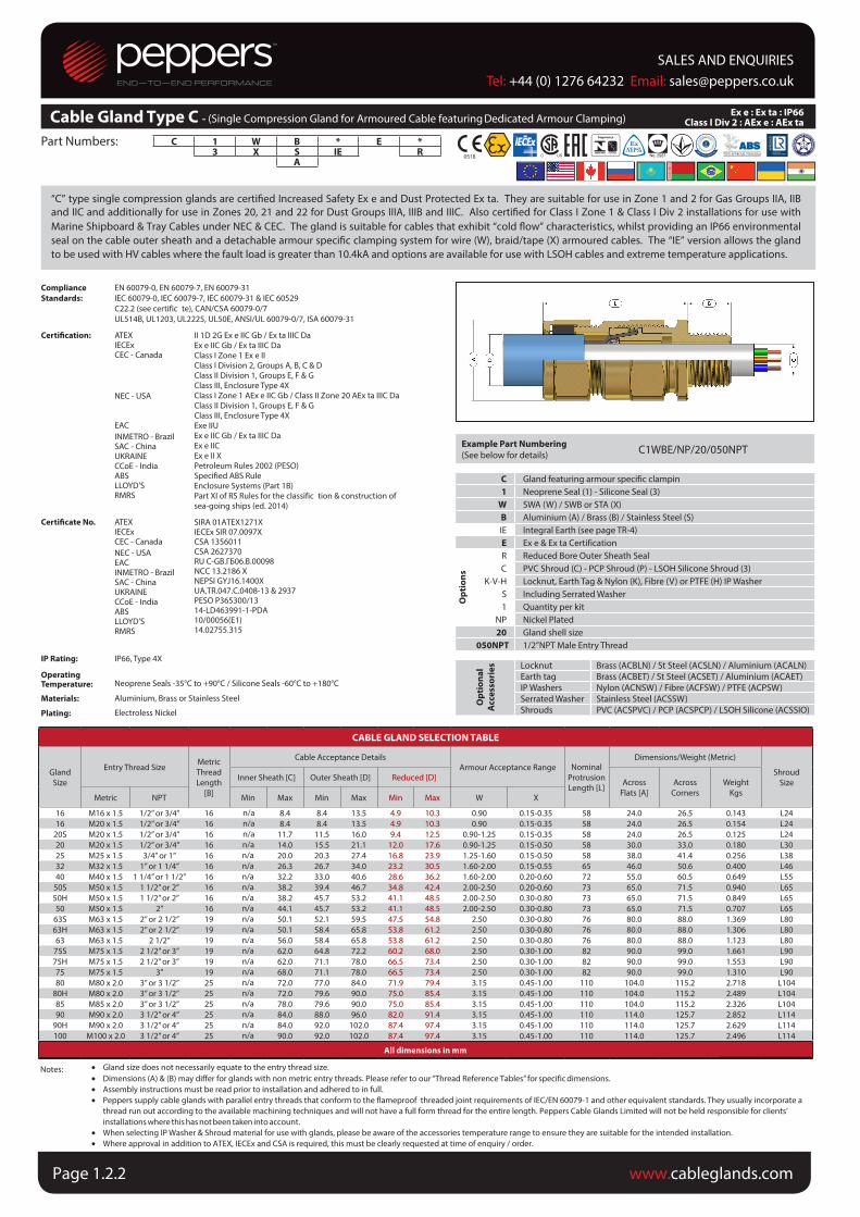
“C” type single compression glands are certiied Increased Safety Ex e and Dust Protected Ex ta. They are suitable for use in Zone 1 and 2 for Gas Groups IIA, IIB and IIC and additionally for use in Zones 20, 21 and 22 for Dust Groups IIIA, IIIB and IIIC. Also certiied for Class I Zone 1 & Class I Div 2 installations for use with Marine Shipboard & Tray Cables under NEC & CEC. The gland is suitable for cables that exhibit “cold low” characteristics, whilst providing an IP66 environmental seal on the cable outer sheath and a detachable armour speciic clamping system for wire (W), braid/tape (X) armoured cables. The “IE” version allows the gland to be used with HV cables where the fault load is greater than 10.4kA and options are available for use with LSOH cables and extreme temperature applications.
Compliance
Standards:
EN 60079-0, EN 60079-7, EN 60079-31IEC 60079-0, IEC 60079-7, IEC 60079-31 & IEC 60529C22.2 (see certific te), CAN/CSA 60079-0/7UL514B, UL1203, UL2225, UL50E, ANSI/UL 60079-0/7, ISA 60079-31
Certiication: ATEXIECExCEC - Canada
NEC - USA
EACINMETRO - BrazilSAC - ChinaUKRAINECCoE - IndiaABSLLOYD’SRMRS
Certiicate No. ATEXIECExCEC - CanadaNEC - USAEACINMETRO - BrazilSAC - ChinaUKRAINECCoE - IndiaABSLLOYD’SRMRS
II 1D 2G Ex e IIC Gb / Ex ta IIIC DaEx e IIC Gb / Ex ta IIIC DaClass I Zone 1 Ex e IIClass I Division 2, Groups A, B, C & DClass II Division 1, Groups E, F & GClass III, Enclosure Type 4XClass I Zone 1 AEx e IIC Gb / Class II Zone 20 AEx ta IIIC Da Class II Division 1, Groups E, F & GClass III, Enclosure Type 4XExe IIUEx e IIC Gb / Ex ta IIIC DaEx e IICEx e II XPetroleum Rules 2002 (PESO)Specified ABS RuleEnclosure Systems (Part 1B)Part XI of RS Rules for the classific tion & construction of sea-going ships (ed. 2014)
SIRA 01ATEX1271XIECEx SIR 07.0097XCSA 1356011CSA 2627370RU C-GB.ГБ06.В.00098NCC 13.2186 XNEPSI GYJ16.1400XUA.TR.047.C.0408-13 & 2937PESO P365300/1314-LD463991-1-PDA10/00056(E1)14.02755.315
IP Rating:
OperatingTemperature:
Materials:
Plating:
IP66, Type 4X
Neoprene Seals -35°C to +90°C / Silicone Seals -60°C to +180°C
Aluminium, Brass or Stainless Steel
Electroless Nickel
Example Part Numbering
(See below for details) C1WBE/NP/20/050NPT
C Gland featuring armour specific clampin1 Neoprene Seal (1) - Silicone Seal (3)
W SWA (W) / SWB or STA (X)B Aluminium (A) / Brass (B) / Stainless Steel (S)IE Integral Earth (see page TR-4)E Ex e & Ex ta Certification
Op
tio
ns
R Reduced Bore Outer Sheath SealC PVC Shroud (C) - PCP Shroud (P) - LSOH Silicone Shroud (3)
K-V-H Locknut, Earth Tag & Nylon (K), Fibre (V) or PTFE (H) IP WasherS Including Serrated Washer1 Quantity per kit
NP Nickel Plated 20 Gland shell size
050NPT 1/2”NPT Male Entry Thread
Op
tio
na
l
Acc
ess
ori
es Locknut Brass (ACBLN) / St Steel (ACSLN) / Aluminium (ACALN)
Earth tag Brass (ACBET) / St Steel (ACSET) / Aluminium (ACAET)IP Washers Nylon (ACNSW) / Fibre (ACFSW) / PTFE (ACPSW)Serrated Washer Stainless Steel (ACSSW)Shrouds PVC (ACSPVC) / PCP (ACSPCP) / LSOH Silicone (ACSSIO)
CABLE GLAND SELECTION TABLE
GlandSize
Entry Thread SizeMetric ThreadLength
[B]
Cable Acceptance DetailsArmour Acceptance Range Nominal
ProtrusionLength [L]
Dimensions/Weight (Metric)
ShroudSizeInner Sheath [C] Outer Sheath [D] Reduced [D] Across
Flats [A]Across
Corners Weight
KgsMetric NPT Min Max Min Max Min Max W X
16 M16 x 1.5 1/2” or 3/4” 16 n/a 8.4 8.4 13.5 4.9 10.3 0.90 0.15-0.35 58 24.0 26.5 0.143 L2416 M20 x 1.5 1/2” or 3/4” 16 n/a 8.4 8.4 13.5 4.9 10.3 0.90 0.15-0.35 58 24.0 26.5 0.154 L24
20S M20 x 1.5 1/2” or 3/4” 16 n/a 11.7 11.5 16.0 9.4 12.5 0.90-1.25 0.15-0.35 58 24.0 26.5 0.125 L2420 M20 x 1.5 1/2” or 3/4” 16 n/a 14.0 15.5 21.1 12.0 17.6 0.90-1.25 0.15-0.50 58 30.0 33.0 0.180 L3025 M25 x 1.5 3/4” or 1” 16 n/a 20.0 20.3 27.4 16.8 23.9 1.25-1.60 0.15-0.50 58 38.0 41.4 0.256 L3832 M32 x 1.5 1” or 1 1/4” 16 n/a 26.3 26.7 34.0 23.2 30.5 1.60-2.00 0.15-0.55 65 46.0 50.6 0.400 L4640 M40 x 1.5 1 1/4” or 1 1/2” 16 n/a 32.2 33.0 40.6 28.6 36.2 1.60-2.00 0.20-0.60 72 55.0 60.5 0.649 L55
50S M50 x 1.5 1 1/2” or 2” 16 n/a 38.2 39.4 46.7 34.8 42.4 2.00-2.50 0.20-0.60 73 65.0 71.5 0.940 L6550H M50 x 1.5 1 1/2” or 2” 16 n/a 38.2 45.7 53.2 41.1 48.5 2.00-2.50 0.30-0.80 73 65.0 71.5 0.849 L6550 M50 x 1.5 2” 16 n/a 44.1 45.7 53.2 41.1 48.5 2.00-2.50 0.30-0.80 73 65.0 71.5 0.707 L65
63S M63 x 1.5 2” or 2 1/2” 19 n/a 50.1 52.1 59.5 47.5 54.8 2.50 0.30-0.80 76 80.0 88.0 1.369 L8063H M63 x 1.5 2” or 2 1/2” 19 n/a 50.1 58.4 65.8 53.8 61.2 2.50 0.30-0.80 76 80.0 88.0 1.306 L8063 M63 x 1.5 2 1/2” 19 n/a 56.0 58.4 65.8 53.8 61.2 2.50 0.30-0.80 76 80.0 88.0 1.123 L80
75S M75 x 1.5 2 1/2” or 3” 19 n/a 62.0 64.8 72.2 60.2 68.0 2.50 0.30-1.00 82 90.0 99.0 1.661 L9075H M75 x 1.5 2 1/2” or 3” 19 n/a 62.0 71.1 78.0 66.5 73.4 2.50 0.30-1.00 82 90.0 99.0 1.553 L9075 M75 x 1.5 3” 19 n/a 68.0 71.1 78.0 66.5 73.4 2.50 0.30-1.00 82 90.0 99.0 1.310 L9080 M80 x 2.0 3” or 3 1/2” 25 n/a 72.0 77.0 84.0 71.9 79.4 3.15 0.45-1.00 110 104.0 115.2 2.718 L104
80H M80 x 2.0 3” or 3 1/2” 25 n/a 72.0 79.6 90.0 75.0 85.4 3.15 0.45-1.00 110 104.0 115.2 2.489 L10485 M85 x 2.0 3” or 3 1/2” 25 n/a 78.0 79.6 90.0 75.0 85.4 3.15 0.45-1.00 110 104.0 115.2 2.326 L10490 M90 x 2.0 3 1/2” or 4” 25 n/a 84.0 88.0 96.0 82.0 91.4 3.15 0.45-1.00 110 114.0 125.7 2.852 L114
90H M90 x 2.0 3 1/2” or 4” 25 n/a 84.0 92.0 102.0 87.4 97.4 3.15 0.45-1.00 110 114.0 125.7 2.629 L114100 M100 x 2.0 3 1/2” or 4” 25 n/a 90.0 92.0 102.0 87.4 97.4 3.15 0.45-1.00 110 114.0 125.7 2.496 L114
All dimensions in mm
Notes: • Gland size does not necessarily equate to the entry thread size.• Dimensions (A) & (B) may differ for glands with non metric entry threads. Please refer to our “Thread Reference Tables” for specific dimensions.• Assembly instructions must be read prior to installation and adhered to in full.• Peppers supply cable glands with parallel entry threads that conform to the flameproof threaded joint requirements of IEC/EN 60079-1 and other equivalent standards. They usually incorporate a
thread run out according to the available machining techniques and will not have a full form thread for the entire length. Peppers Cable Glands Limited will not be held responsible for clients’ installations where this has not been taken into account.
• When selecting IP Washer & Shroud material for use with glands, please be aware of the accessories temperature range to ensure they are suitable for the intended installation.• Where approval in addition to ATEX, IECEx and CSA is required, this must be clearly requested at time of enquiry / order.
Ex e : Ex ta : IP66 Class I Div 2 : AEx e : AEx taCable Gland Type C - (Single Compression Gland for Armoured Cable featuring Dedicated Armour Clamping)
SALES AND ENQUIRIESTel: +44 (0) 1276 64232 Email: [email protected]
www.cableglands.comPage 1.2.2
Part Numbers:
Notes:
A 1 L B F2 S E3 A4
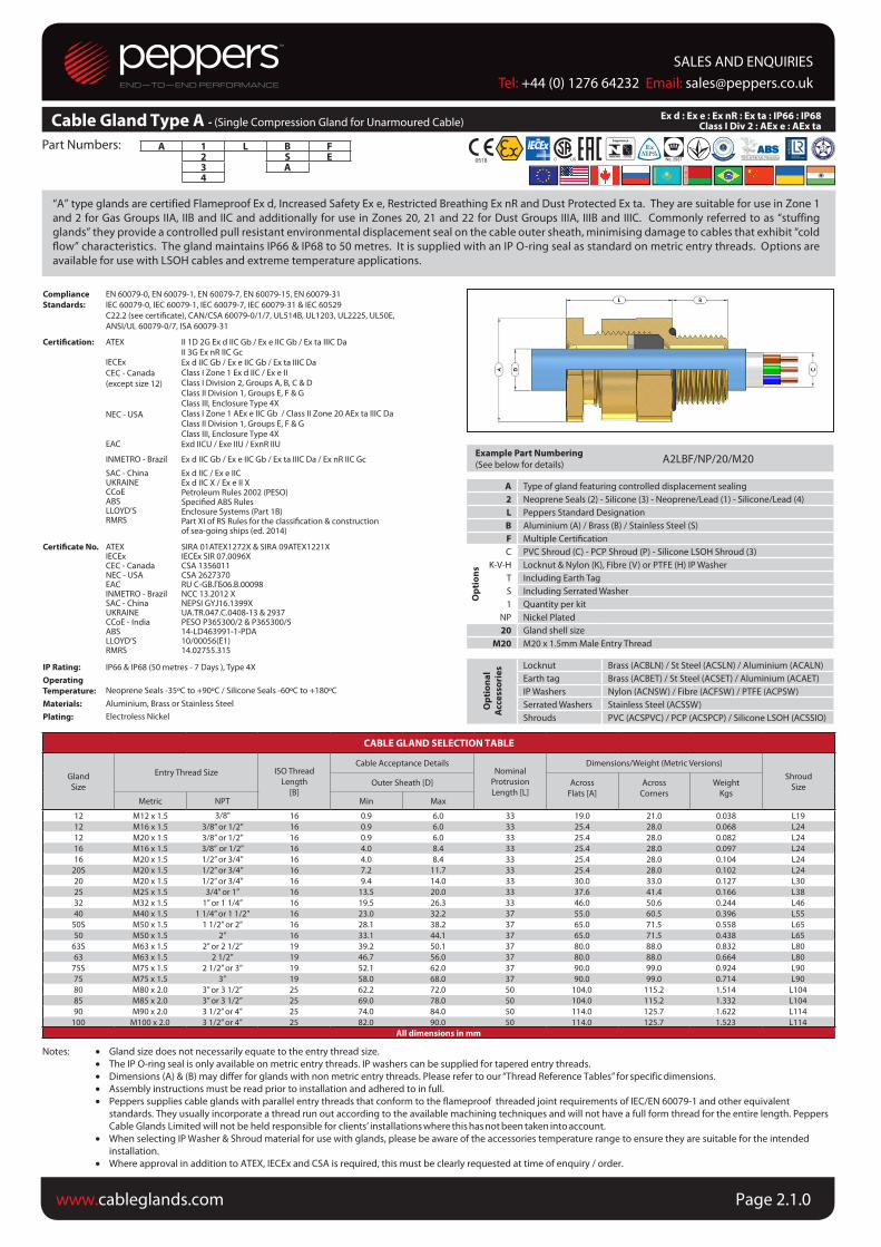
“A” type glands are certified Flameproof Ex d, Increased Safety Ex e, Restricted Breathing Ex nR and Dust Protected Ex ta. They are suitable for use in Zone 1
and 2 for Gas Groups IIA, IIB and IIC and additionally for use in Zones 20, 21 and 22 for Dust Groups IIIA, IIIB and IIIC. Commonly referred to as “stuffing
glands” they provide a controlled pull resistant environmental displacement seal on the cable outer sheath, minimising damage to cables that exhibit “cold
low” characteristics. The gland maintains IP66 & IP68 to 50 metres. It is supplied with an IP O-ring seal as standard on metric entry threads. Options are
available for use with LSOH cables and extreme temperature applications.
• Gland size does not necessarily equate to the entry thread size.
• The IP O-ring seal is only available on metric entry threads. IP washers can be supplied for tapered entry threads.
• Dimensions (A) & (B) may differ for glands with non metric entry threads. Please refer to our “Thread Reference Tables” for specific dimensions.
• Assembly instructions must be read prior to installation and adhered to in full.
• Peppers supplies cable glands with parallel entry threads that conform to the flameproof threaded joint requirements of IEC/EN 60079-1 and other equivalent
standards. They usually incorporate a thread run out according to the available machining techniques and will not have a full form thread for the entire length. Peppers Cable Glands Limited will not be held responsible for clients’ installations where this has not been taken into account.
• When selecting IP Washer & Shroud material for use with glands, please be aware of the accessories temperature range to ensure they are suitable for the intended
installation.
• Where approval in addition to ATEX, IECEx and CSA is required, this must be clearly requested at time of enquiry / order.
Compliance
Standards:
EN 60079-0, EN 60079-1, EN 60079-7, EN 60079-15, EN 60079-31
IEC 60079-0, IEC 60079-1, IEC 60079-7, IEC 60079-31 & IEC 60529
C22.2 (see certiicate), CAN/CSA 60079-0/1/7, UL514B, UL1203, UL2225, UL50E,
ANSI/UL 60079-0/7, ISA 60079-31
Certiication: ATEX
IECEx
CEC - Canada
(except size 12)
NEC - USA
EAC
II 1D 2G Ex d IIC Gb / Ex e IIC Gb / Ex ta IIIC DaII 3G Ex nR IIC GcEx d IIC Gb / Ex e IIC Gb / Ex ta IIIC DaClass I Zone 1 Ex d IIC / Ex e IIClass I Division 2, Groups A, B, C & DClass II Division 1, Groups E, F & GClass III, Enclosure Type 4XClass I Zone 1 AEx e IIC Gb / Class II Zone 20 AEx ta IIIC Da Class II Division 1, Groups E, F & GClass III, Enclosure Type 4XExd IICU / Exe IIU / ExnR IIU
INMETRO - Brazil Ex d IIC Gb / Ex e IIC Gb / Ex ta IIIC Da / Ex nR IIC Gc
SAC - ChinaUKRAINECCoEABSLLOYD’SRMRS
Certiicate No. ATEXIECExCEC - CanadaNEC - USAEAC
Ex d IIC / Ex e IICEx d IIC X / Ex e II XPetroleum Rules 2002 (PESO)Speciied ABS RulesEnclosure Systems (Part 1B)Part XI of RS Rules for the classiication & construction of sea-going ships (ed. 2014)
SIRA 01ATEX1272X & SIRA 09ATEX1221XIECEx SIR 07.0096XCSA 1356011CSA 2627370RU C-GB.ГБ06.В.00098
INMETRO - Brazil NCC 13.2012 XSAC - ChinaUKRAINECCoE - IndiaABSLLOYD’SRMRS
NEPSI GYJ16.1399XUA.TR.047.C.0408-13 & 2937 PESO P365300/2 & P365300/5 14-LD463991-1-PDA10/00056(E1)14.02755.315
IP Rating: IP66 & IP68 (50 metres - 7 Days ), Type 4X
Operating
Temperature:
Materials:
Plating:
Neoprene Seals -35ºC to +90ºC / Silicone Seals -60ºC to +180ºC Aluminium, Brass or Stainless Steel
Electroless Nickel
Example Part Numbering
(See below for details)A2LBF/NP/20/M20
A Type of gland featuring controlled displacement sealing
2 Neoprene Seals (2) - Silicone (3) - Neoprene/Lead (1) - Silicone/Lead (4)
L Peppers Standard Designation
B Aluminium (A) / Brass (B) / Stainless Steel (S)
F Multiple Certiication
Op
tio
ns
C PVC Shroud (C) - PCP Shroud (P) - Silicone LSOH Shroud (3)
K-V-H Locknut & Nylon (K), Fibre (V) or PTFE (H) IP Washer
T Including Earth Tag
S Including Serrated Washer
1 Quantity per kit
NP Nickel Plated
20 Gland shell size
M20 M20 x 1.5mm Male Entry Thread
Op
tio
na
l
Acc
ess
ori
es Locknut Brass (ACBLN) / St Steel (ACSLN) / Aluminium (ACALN)
Earth tag Brass (ACBET) / St Steel (ACSET) / Aluminium (ACAET)IP Washers Nylon (ACNSW) / Fibre (ACFSW) / PTFE (ACPSW)
Serrated Washers Stainless Steel (ACSSW)
Shrouds PVC (ACSPVC) / PCP (ACSPCP) / Silicone LSOH (ACSSIO)
CABLE GLAND SELECTION TABLE
Gland
Size
Entry Thread Size ISO Thread
Length
[B]
Cable Acceptance DetailsNominal
Protrusion
Length [L]
Dimensions/Weight (Metric Versions)
Shroud
SizeOuter Sheath [D] Across
Flats [A]
Across
Corners
Weight
KgsMetric NPT Min Max
12 M12 x 1.5 3/8" 16 0.9 6.0 33 19.0 21.0 0.038 L19
12 M16 x 1.5 3/8” or 1/2” 16 0.9 6.0 33 25.4 28.0 0.068 L24
12 M20 x 1.5 3/8” or 1/2” 16 0.9 6.0 33 25.4 28.0 0.082 L24
16 M16 x 1.5 3/8” or 1/2" 16 4.0 8.4 33 25.4 28.0 0.097 L24
16 M20 x 1.5 1/2” or 3/4” 16 4.0 8.4 33 25.4 28.0 0.104 L24
20S M20 x 1.5 1/2” or 3/4” 16 7.2 11.7 33 25.4 28.0 0.102 L24
20 M20 x 1.5 1/2” or 3/4” 16 9.4 14.0 33 30.0 33.0 0.127 L30
25 M25 x 1.5 3/4” or 1” 16 13.5 20.0 33 37.6 41.4 0.166 L38
32 M32 x 1.5 1” or 1 1/4” 16 19.5 26.3 33 46.0 50.6 0.244 L46
40 M40 x 1.5 1 1/4” or 1 1/2” 16 23.0 32.2 37 55.0 60.5 0.396 L55
50S M50 x 1.5 1 1/2” or 2” 16 28.1 38.2 37 65.0 71.5 0.558 L65
50 M50 x 1.5 2” 16 33.1 44.1 37 65.0 71.5 0.438 L65
63S M63 x 1.5 2” or 2 1/2” 19 39.2 50.1 37 80.0 88.0 0.832 L80
63 M63 x 1.5 2 1/2” 19 46.7 56.0 37 80.0 88.0 0.664 L80
75S M75 x 1.5 2 1/2” or 3” 19 52.1 62.0 37 90.0 99.0 0.924 L90
75 M75 x 1.5 3” 19 58.0 68.0 37 90.0 99.0 0.714 L90
80 M80 x 2.0 3” or 3 1/2” 25 62.2 72.0 50 104.0 115.2 1.514 L104
85 M85 x 2.0 3” or 3 1/2” 25 69.0 78.0 50 104.0 115.2 1.332 L104
90 M90 x 2.0 3 1/2” or 4” 25 74.0 84.0 50 114.0 125.7 1.622 L114
100 M100 x 2.0 3 1/2” or 4” 25 82.0 90.0 50 114.0 125.7 1.523 L114
All dimensions in mm
Ex d : Ex e : Ex nR : Ex ta : IP66 : IP68 Class I Div 2 : AEx e : AEx taCable Gland Type A - (Single Compression Gland for Unarmoured Cable)
SALES AND ENQUIRIESTel: +44 (0) 1276 64232 Email: [email protected]
www.cableglands.com Page 2.1.0

Cable Gland Type CR (featuring “CROCLOCK®”) Ex d : Ex e : Ex nR : Ex tD A21 : IP66 : IP68
Part Numbers:
Notes:
Cable Gland Type A*LDS - (Double Compression Gland designed for use with Unarmoured Cable)Ex d : Ex e : Ex nR : Ex ta : IP66 : IP68
Class I Div 2 : AEx e : AEx ta
“A*LDS” type glands are certiied Flameproof Ex d, Increased Safety Ex e, Restricted Breathing Ex nR and Dust Protected Ex ta. They are suitable for use
in Zone 1 and 2 for Gas Groups IIA, IIB and IIC and additionally for use in Zones 20, 21 and 22 for Dust Groups IIIA, IIIB and IIIC. Commonly referred to as
“double seal stuing glands” they provide two controlled pull resistant environmental displacement seals on the cable outer sheath, minimising damage to
cables that exhibit “cold low” characteristics. The gland maintains IP66 & IP68 to 50 metres. It is supplied with an IP O-ring seal as standard on metric entry
threads. Options are available for use with LSOH cables and extreme temperature applications.
• Gland size does not necessarily equate to the entry thread size.
• The IP O-ring seal is only available on metric entry threads. IP washers can be supplied for tapered entry threads.
• Dimensions (A) & (B) may differ for glands with non metric entry threads. Please refer to our “Thread Reference Tables” for specific dimensions.
• Assembly instructions must be read prior to installation and adhered to in full.
• Peppers supplies cable glands with parallel entry threads that conform to the flameproof threaded joint requirements of IEC/EN 60079-1 and other equivalent
standards. They usually incorporate a thread run out according to the available machining techniques and will not have a full form thread for the entire length. Peppers Cable Glands Limited will not be held responsible for clients’ installations where this has not been taken into account.
• When selecting IP Washer & Shroud material for use with glands, please be aware of the accessories temperature range to ensure they are suitable for the intended
installation.
• Where approval in addition to ATEX, IECEx and CSA is required, this must be clearly requested at time of enquiry / order.
A 1 L DS B F2 S3 A4
Compliance
Standards:
EN 60079-0, EN 60079-1, EN 60079-7, EN 60079-15, EN 60079-31
IEC 60079-0, IEC 60079-1, IEC 60079-7, IEC 60079-31 & IEC 60529
C22.2 (see certiicate), CAN/CSA 60079-0/1/7, UL514B, UL1203, UL2225, UL50E
ANSI/UL 60079-0/7, ISA 60079-31
Certiication: ATEX
IECEx
CEC - Canada
(except size 12)
NEC - USA
EAC
II 1D 2G Ex d IIC Gb / Ex e IIC Gb / Ex ta IIIC DaII 3G Ex nR IIC GcEx d IIC Gb / Ex e IIC Gb / Ex ta IIIC DaClass I Zone 1 Ex d IIC / Ex e IIClass I Division 2, Groups A, B, C & DClass II Division 1, Groups E, F & GClass III, Enclosure Type 4XClass I Zone 1 AEx e IIC Gb / Class II Zone 20 AEx ta IIIC Da Class II Division 1, Groups E, F & GClass III, Enclosure Type 4XExd IICU / Exe IIU / ExnR IIU
INMETRO - Brazil Ex d IIC Gb / Ex e IIC Gb / Ex ta IIIC Da / Ex nR IIC Gc
SAC - China Ex d IIC / Ex e IICUKRAINE Ex d IIC X / Ex e II XCCoE - India Petroleum Rules 2002 (PESO)ABS Speciied ABS RulesLLOYD’S Enclosure Systems (Part 1B)RMRS Part XI of RS Rules for the classiication & construction
of sea-going ships (ed. 2014)
Certiicate No. ATEX SIRA 01ATEX1272X & SIRA 09ATEX1221XIECEx IECEx SIR 07.0096XCEC - Canada CSA 1356011NEC - USA CSA 2627370EAC RU C-GB.ГБ06.В.00098INMETRO - Brazil NCC 13.2012 XSAC - China NEPSI GYJ16.1399XUKRAINE UA.TR.047.C.0408-13 & 2937CCoE - India PESO P365300/2 & P365300/5ABS 14-LD463991-1-PDALLOYD’S 10/00056(E1)RMRS 14.02755.315
IP Rating:
Operating
Temperature:
Materials:
Plating:
IP66 & IP68 (50 metres - 7 Days), Type 4X
Neoprene Seals -35ºC to +90ºC / Silicone Seals -60ºC to +180ºC
Aluminium, Brass or Stainless Steel
Electroless Nickel
Example Part Numbering
(See below for details)A2LDSBF/NP/20/M20
A Gland featuring controlled displacement sealing
2 Neoprene Seals (2) - Silicone Seals (3) - Neoprene/Lead (1) - Silicone/Lead (4)
L Peppers Standard Designation
DS Double Sealing
B Aluminium (A) / Brass (B) / Stainless Steel (S)
F Multiple Certiication
Op
tio
ns
C PVC Shroud (C) - PCP Shroud (P) - LSOH Silicone Shroud (3)
K-V-H Locknut & Nylon (K), Fibre (V) or PTFE (H) IP Washer
T Including Earth Tag
S Including Serrated Washer
1 Quantity per kit
NP Nickel Plated
20 Gland shell size
M20 M20 x 1.5mm Male Entry Thread
Op
tio
na
l
Acc
ess
ori
es Locknut Brass (ACBLN) / St Steel (ACSLN) / Aluminium (ACALN)
Earth tag Brass (ACBET) / St Steel (ACSET) / Aluminium (ACAET)IP Washers Nylon (ACNSW) / Fibre (ACFSW) / PTFE (ACPSW)
Serrated Washers Stainless Steel (ACSSW)
Shrouds PVC (ACSPVC) / PCP (ACSPCP) / LSOH Silicone(ACSSIO)
CABLE GLAND SELECTION TABLE
Gland
Size
Entry Thread Size Metric
Thread
Length
[B]
Cable Acceptance Details
Outer Sheath [D]Nominal
Protrusion
Length [L]
(Metric)
Dimensions/Weight (Metric Versions)
Shroud
SizeAcross
Flats [A]
Across
Corners
Weight
Kgs (Metric)Metric NPT Min Max
12 M12 x 1.5 3/8" 16 0.9 6.0 33 19.0 21.0 0.064 L19
12 M16 x 1.5 3/8” or 1/2” 16 0.9 6.0 33 25.4 28.0 0.119 L24
16 M16 x 1.5 1/2” or 3/4” 16 4.0 8.4 48 25.4 28.0 0.133 L24
20S M20 x 1.5 1/2” or 3/4” 16 7.2 11.7 48 25.4 28.0 0.209 L24
20 M20 x 1.5 1/2” or 3/4” 16 9.4 14.0 62 30.0 33.0 0.275 L30
25 M25 x 1.5 3/4” or 1” 16 13.5 20.0 62 37.6 41.4 0.408 L38
32 M32 x 1.5 1” or 1 1/4” 16 19.5 26.3 62 46.0 50.6 0.408 L46
40 M40 x 1.5 1 1/4” or 1 1/2” 16 23.0 32.2 68 55.0 60.5 0.666 L55
50S M50 x 1.5 1 1/2” or 2” 16 28.1 38.2 68 65.0 71.5 0.896 L65
50 M50 x 1.5 2” 16 33.1 44.1 74 65.0 71.5 0.736 L65
63S M63 x 1.5 2” or 2 1/2” 19 39.2 50.1 74 80.0 88.0 1.330 L80
63 M63 x 1.5 2 1/2” 19 46.7 56.0 74 80.0 88.0 1.114 L80
75S M75 x 1.5 2 1/2” or 3” 19 52.1 62.0 74 90.0 99.0 1.493 L90
75 M75 x 1.5 3” 19 58.0 68.0 74 90.0 99.0 1.218 L90
80 M80 x 2.0 3” or 3 1/2” 25 62.2 72.0 87 104.0 115.2 2.322 L104
85 M85 x 2.0 3” or 3 1/2” 25 69.0 78.0 104.0 115.2 2.107 L104
90 M90 x 2.0 3 1/2” or 4” 25 74.0 84.0 114.0 125.7 2.539 L114
100 M100 x 2.0 3 1/2” or 4” 25 82.0 90.0 114.0 125.7 2.211 L114
All dimensions in mm
SALES AND ENQUIRIESTel: +44 (0) 1276 64232 Email: [email protected]
www.cableglands.comPage 2.2.0
878890

Part Numbers:
Notes:
“A*RCC” type glands are certiied Flameproof Ex d, Increased Safety Ex e, Restricted Breathing Ex nR and Dust Protected Ex ta. They are suitable for use in
Zone 1 and 2 for Gas Groups IIA, IIB and IIC and additionally for use in Zones 20, 21 and 22 for Dust Groups IIIA, IIIB and IIIC. Commonly referred to as “stuffing
glands”, they provide a controlled pull resistant environmental displacement seal on the cable outer sheath, minimising damage to cables that exhibit “cold
low” characteristics. The gland maintains IP66 & IP68 to 50 metres. It is supplied with an IP O-ring seal as standard on metric entry threads. The gland
features a freely rotating lexible conduit connection.
• Gland size does not necessarily equate to the entry thread size.
• The IP O-ring seal is only available on metric entry threads. IP washers can be supplied for tapered entry threads.
• Dimensions (A) & (B) may differ for glands with non metric entry threads. Please refer to our “Thread Reference Tables” for specific dimensions.
• Assembly instructions must be read prior to installation and adhered to in full.
• Peppers supplies cable glands with parallel entry threads that conform to the flameproof threaded joint requirements of IEC/EN 60079-1 and other equivalent
standards. They usually incorporate a thread run out according to the available machining techniques and will not have a full form thread for the entire length. Peppers Cable Glands Limited will not be held responsible for clients’ installations where this has not been taken into account.
• When selecting IP Washer material for gland kits, please be aware of the accessories temperature range to ensure they are suitable for the intended installation.
• Where approval in addition to ATEX and IECEx is required, this must be clearly requested at time of enquiry / order.
• It is the installer’s responsibility to ensure that the flexible conduit is secured correctly.
• If fit testing is required for specific conduit please contact Peppers.
A 1 R CC B F2 S3 A4
Compliance
Standard:
EN 60079-0, EN 60079-1, EN 60079-7, EN 60079-15, EN 60079-31
IEC 60079-0, IEC 60079-1, IEC 60079-7, IEC 60079-31 & IEC 60529
Certiication: ATEX
IECEx
EAC
INMETRO - Brazil
UKRAINE
CCoE - India
ABS
LLOYD’S
RMRS
Certiicate No. ATEX
IECEx
EAC
INMETRO - BrazilSAC - ChinaUKRAINE
CCoE - India ABS
LLOYD’S
RMRS
II 1D 2G Ex d IIC Gb / Ex e IIC Gb / Ex ta IIIC Da
II 3 G Ex nR IIC Gc
Ex d IIC Gb / Ex e IIC Gb / Ex ta IIIC Da
Exd IICU / Exe IIU / ExnR IIU
Ex d IIC Gb / Ex e IIC Gb / Ex ta IIIC Da / Ex nR IIC Gc
Ex d IIC / Ex e IICEx d IIC X / Ex e II X
Petroleum Rules 2002 (PESO)
Specified ABS Rules
Enclosure Systems (Part 1B)
Part XI of RS Rules for the classification & construction
of sea-going ships (ed. 2014)
SIRA 01ATEX1272X & SIRA 09ATEX1221X
IECEx SIR 07.0096X
RU C-GB.ГБ06.В.00098
NCC 13.2012 X
NEPSI GYJ16.1399XUA.TR.047.C.0408-13 & 2937
PESO P365300/2 & P365300/5
14-LD463991-1-PDA
10/00056(E1)
14.02755.315
IP Rating:
Operating
Temperature:
Materials:Plating:
IP66 & IP68 (50 metres - 7 Days)
Neoprene Seals -35°C to +90°C / Silicone Seals -60°C to +180°C
Aluminium, Brass or Stainless SteelElectroless Nickel
Example Part Numbering
(See below for details)A2RCCBF/NP/20-1/M20
A Gland featuring controlled displacement sealing
2 Neoprene Seal (2) - Silicone Seal (3) - Neoprene/Lead (1) - Silicone/Lead (4)
R Rotating Conduit Design
CC Metallic Flexible Conduit Connector
B Aluminium (A) / Brass (B) / Stainless Steel (S)
F Multiple Certiication
Nickel Plated
20-1 Gland & Connector Size
M20 M20 x 1.5mm Male Entry Thread
Op
tio
na
l
Acc
ess
ori
es Locknut Brass (ACBLN) / Stainless Steel (ACSLN) / Aluminium (ACALN)
Earth tag Brass (ACBET) / Stainless Steel (ACSET) / Aluminium (ACAET)IP Washers Nylon (ACNSW) / Fibre (ACFSW) / PTFE (ACPSW)
Serrated Washers Stainless Steel (ACSSW)
CABLE GLAND SELECTION TABLE
Gland &
Connector
Size
Entry Thread SizeMetric
Thread Length
[B]
Cable Acceptance Details
Outer Sheath [D]Typical Conduit Diameter
Nominal
Protrusion
Length [L]
Dimensions/Weight (Metric Versions)Metric Thread
Shroud SizeAcross Flats [A] Across Corners Weight
Kgs Metric NPT Min Max I/D Max O/D12-1 M12 x 1.5 3/8” 16 0.9 5.4 6.8 10.3 35 19.0 20.9 0.051 n/a12-1 M16 x 1.5 3/8” or 1/2” 16 0.9 5.4 6.8 10.3 34 25.4 28.0 0.059 n/a12-2 M12 x 1.5 3/8” 16 0.9 6.0 9.1 14.3 35 19.0 20.9 0.083 n/a12-2 M16 x 1.5 3/8” or 1/2” 16 0.9 6.0 9.1 14.3 34 25.4 28.0 0.092 n/a12-3 M16 x 1.5 3/8” or 1/2” 16 0.9 6.0 7.7 13.0 34 25.4 28.0 0.107 n/a16-1 M16 x 1.5 3/8” or 1/2” 16 4.0 8.4 10.2 14.1 39 25.4 28.0 0.130 n/a16-1 M20 x 1.5 3/8” or 1/2” 16 4.0 8.4 10.2 14.1 45 25.4 28.0 0.130 n/a16-2 M16 x 1.5 3/8” or 1/2” 16 4.0 8.4 10.9 15.8 39 25.4 28.0 0.130 n/a16-2 M20 x 1.5 3/8” or 1/2” 16 4.0 8.4 10.9 15.8 45 25.4 28.0 0.130 n/a16-3 M16 x 1.5 3/8” or 1/2” 16 4.0 8.4 13.0 17.1 39 25.4 28.0 0.130 n/a16-3 M20 x 1.5 3/8” or 1/2” 16 4.0 8.4 13.0 17.1 45 25.4 28.0 0.130 n/a
20S-1 M20 x 1.5 3/8” or 1/2” 16 7.2 11.0 13.0 17.1 45 25.4 28.0 0.133 n/a20S-2 M20 x 1.5 3/8” or 1/2” 16 7.2 11.7 15.0 19.3 45 25.4 28.0 0.133 n/a20S-3 M20 x 1.5 3/8” or 1/2” 16 7.2 11.7 13.6 20.7 45 25.4 28.0 0.133 n/a20-1 M20 x 1.5 1/2” or 3/4” 16 9.4 14.0 16.9 22.3 45 30.0 33.0 0.162 n/a20-2 M20 x 1.5 1/2” or 3/4” 16 9.4 14.0 18.0 23.8 45 30.0 33.0 0.162 n/a20-3 M20 x 1.5 1/2” or 3/4” 16 9.4 14.0 18.7 24.8 45 30.0 33.0 0.174 n/a20-4 M20 x 1.5 1/2” or 3/4” 16 9.4 14.0 20.7 28.3 45 30.0 33.0 0.195 n/a20-5 M20 x 1.5 1/2” or 3/4” 16 9.4 13.0 13.9 19.3 45 30.0 33.0 0.210 n/a25-1 M25 x 1.5 3/4” or 1” 16 13.5 20.0 23.7 31.3 46 37.6 41.4 0.256 n/a25-2 M25 x 1.5 3/4” or 1” 16 13.5 19.0 21.1 26.8 46 37.6 41.4 0.231 n/a25-3 M25 x 1.5 3/4” or 1” 16 13.5 19.0 24.3 31.3 46 37.6 41.4 0.234 n/a25-4 M25 x 1.5 3/4” or 1” 16 13.5 20.0 22.3 28.3 46 37.6 41.4 0.234 n/a32-1 M32 x 1.5 1” or 1 1/4” 16 19.5 26.0 28.1 33.3 47 46.0 50.6 0.322 n/a32-2 M32 x 1.5 1” or 1 1/4” 16 19.5 26.3 30.4 38.2 47 46.0 50.6 0.347 n/a32-3 M32 x 1.5 1” or 1 1/4” 16 19.5 26.3 30.4 40.2 47 46.0 50.6 0.369 n/a40-1 M40 x 1.5 1 1/4” or 1 1/2” 16 23.0 32.2 36.4 46.2 50 55.0 60.5 0.518 n/a40-2 M40 x 1.5 1 1/4” or 1 1/2” 16 23.0 32.2 36.4 44.2 50 55.0 60.5 0.497 n/a40-3 M40 x 1.5 1 1/4” or 1 1/2” 16 23.0 32.2 37.7 44.7 50 55.0 60.5 0.484 n/a
50S-1 M50 x 1.5 1 1/2” or 2” 16 28.1 38.2 48.4 55.8 50 65.0 71.5 0.630 n/a50-1 M50 x 1.5 2” 16 33.1 44.1 48.4 55.8 50 65.0 71.5 0.575 n/a
63S-1 M63 x 1.5 2” or 2 1/2” 19 39.2 50.1 57.5 64.8 50 80.0 88.0 0.990 n/a63-1 M63 x 1.5 2 1/2” 19 46.7 53.6 57.5 64.8 50 80.0 88.0 0.900 n/a
All dimensions in mm
Cable Gland Type A*RCC -
NP
SAC - China
(Single Compression Gland featuring a Freely Rotating Flexible Metallic Conduit Connector) Ex d : Ex e : Ex nR : Ex ta : IP66 : IP68
SALES AND ENQUIRIESTel: +44 (0) 1276 64232 Email: [email protected]
www.cableglands.com Page 2.3.0
Cable Gland Type CR (featuring “CROCLOCK®”) Ex d : Ex e : Ex nR : Ex tD A21 : IP66 : IP68
Part Numbers:
Notes:
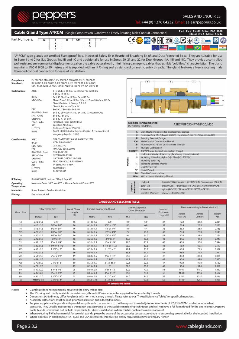
Cable Gland Type A*RCM - (Single Compression Gland with a Freely Rotating Male Conduit Connection)Ex d : Ex e : Ex nR : Ex ta : IP66 : IP68
Class I Div 2 : AEx e : AEx ta
“A*RCM” type glands are certiied Flameproof Ex d, Increased Safety Ex e, Restricted Breathing Ex nR and Dust Protected Ex ta. They are suitable for use
in Zone 1 and 2 for Gas Groups IIA, IIB and IIC and additionally for use in Zones 20, 21 and 22 for Dust Groups IIIA, IIIB and IIIC. They provide a controlled
pull resistant environmental displacement seal on the cable outer sheath, minimising damage to cables that exhibit “cold low” characteristics. The gland
maintains IP66 & IP68 to 50 metres and is supplied with an IP O-ring seal as standard on metric entry threads. The gland features a freely rotating male
threaded conduit connection for ease of installation.
• Gland size does not necessarily equate to the entry thread size.
• The IP O-ring seal is only available on metric entry threads. IP washers can be supplied for tapered entry threads.
• Dimensions (A) & (B) may differ for glands with non metric entry threads. Please refer to our “Thread Reference Tables” for specific dimensions.
• Assembly instructions must be read prior to installation and adhered to in full.
• Peppers supplies cable glands with parallel entry threads that conform to the flameproof threaded joint requirements of IEC/EN 60079-1 and other equivalent
standards. They usually incorporate a thread run out according to the available machining techniques and will not have a full form thread for the entire length. Peppers
Cable Glands Limited will not be held responsible for clients’ installations where this has not been taken into account.
• When selecting IP Washer material for use with glands, please be aware of the accessories temperature range to ensure they are suitable for the intended installation.
• Where approval in addition to ATEX, IECEx and CSA is required, this must be clearly requested at time of enquiry / order.
A 1 R CM B F2 S3 A4
Compliance
Standards:
EN 60079-0, EN 60079-1, EN 60079-7, EN 60079-15, EN 60079-31
IEC 60079-0, IEC 60079-1, IEC 60079-7, IEC 60079-31 & IEC 60529
UL514B, UL1203, UL2225, UL50E, ANSI/UL 60079-0/7, ISA 60079-31
Certiication: ATEX
IECEx
NEC - USA
EAC
INMETRO - Brazil
SAC - China
UKRAINE
CCoE - India
ABS
LLOYD’S
RMRS
Certiicate No. ATEX
IECEx
NEC - USA
EAC
INMETRO - Brazil
SAC - China
UKRAINE
CCoE - India
ABS
LLOYD’S
RMRS
II 1D 2G Ex d IIC Gb / Ex e IIC Gb / Ex ta IIIC Da
II 3G Ex nR IIC Gc
Ex d IIC Gb / Ex e IIC Gb / Ex ta IIIC Da
Class I Zone 1 AEx e IIC Gb / Class II Zone 20 AEx ta IIIC Da Class II Division 1, Groups E, F & G
Class III, Enclosure Type 4X
Exd IICU / Exe IIU / ExnR IIU
Ex d IIC Gb / Ex e IIC Gb / Ex ta IIIC Da / Ex nR IIC Gc
Ex d IIC / Ex e IIC
Ex d IIC X / Ex e II X
Petroleum Rules 2002 (PESO)
Specified ABS Rules
Enclosure Systems (Part 1B)
Part XI of RS Rules for the classification & construction of
sea-going ships (ed. 2014)
SIRA 01ATEX1272X & SIRA 09ATEX1221X
IECEx SIR 07.0096X
CSA 2627370
RU C-GB.ГБ06.В.00098
NCC 13.2012 X
NEPSI GYJ16.1399X
UA.TR.047.C.0408-13 & 2937
PESO P365300/2 & P365300/5
14-LD463991-1-PDA
10/00056(E1)
14.02755.315
IP Rating:
Operating
Temperature:
Materials:
Plating:
IP66 & IP68 (50 metres - 7 Days), Type 4X
Neoprene Seals -35°C to +90°C / Silicone Seals -60°C to +180°C
Brass, Stainless Steel or Aluminium
Electroless Nickel
CABLE GLAND SELECTION TABLE
Gland Size
Entry Thread Size Metric Thread
Length
[B]
Conduit Connection ThreadCable Acceptance
Outer Sheath [D] Nominal
Protrusion
Length [L]
Dimensions/Weight (Metric Versions)
Across
Flats [A]
Across
Corners
Weight
KgsMetric NPT Metric NPT Min Max
12 M12 x 1.5 3/8” 16 M12 x 1.5 3/8" 0.9 6.0 34 19.0 21.0 0.061
12 M16 x 1.5 3/8” or 1/2” 16 M16 x 1.5 3/8” or 1/2” 0.9 6.0 32 25.4 28.0 0.121
16 M16 x 1.5 1/2” or 3/4” 16 M16 x 1.5 1/2” or 3/4” 4.0 8.4 38 25.4 28.0 0.133
20S M20 x 1.5 1/2” or 3/4” 16 M20 x 1.5 1/2” or 3/4” 7.2 11.7 43 25.4 28.0 0.149
20 M20 x 1.5 1/2” or 3/4” 16 M20 x 1.5 1/2” or 3/4” 9.4 14.0 43 30.0 33.0 0.174
25 M25 x 1.5 3/4” or 1” 16 M25 x 1.5 3/4” or 1” 13.5 20.0 43 37.6 41.4 0.243
32 M32 x 1.5 1” or 1 1/4” 16 M32 x 1.5 1” or 1 1/4” 19.5 26.3 43 46.0 50.6 0.344
40 M40 x 1.5 1 1/4” or 1 1/2” 16 M40 x 1.5 1 1/4” or 1 1/2” 23.0 32.2 46 55.0 60.5 0.510
50S M50 x 1.5 1 1/2” or 2” 16 M50 x 1.5 1 1/2” or 2” 28.1 38.2 47 65.0 71.5 0.597
50 M50 x 1.5 2” 16 M50 x 1.5 2” 33.1 44.1 47 65.0 71.5 0.540
63S M63 x 1.5 2” or 2 1/2” 19 M63 x 1.5 2” or 2 1/2” 39.2 50.1 47 80.0 88.0 0.921
63 M63 x 1.5 2 1/2” 19 M63 x 1.5 2 1/2” 46.7 56.0 47 80.0 88.0 0.825
75S M75 x 1.5 2 1/2” or 3” 19 M75 x 1.5 2 1/2” or 3” 52.1 62.0 47 90.0 99.0 1.132
75 M75 x 1.5 3” 19 M75 x 1.5 3” 58.0 68.0 47 90.0 99.0 1.011
80 M80 x 2.0 3” or 3 1/2” 25 M80 x 2.0 3” or 3 1/2” 62.2 72.0 58 104.0 115.2 1.852
85 M85 x 2.0 3” or 3 1/2” 25 M85 x 2.0 3” or 3 1/2” 69.0 78.0 58 104.0 115.2 1.667
90 M90 x 2.0 3 1/2” or 4” 25 M90 x 2.0 3 1/2” or 4” 74.0 84.0 59 114.0 125.7 2.041
100 M100 x 2.0 3 1/2” or 4” 25 M100 x 2.0 3 1/2” or 4” 82.0 90.0 60 114.0 125.7 1.986
All dimensions in mm
Example Part Numbering
(See below for details)A2RCMBF050NPT/NP/20/M20
A Gland featuring controlled displacement sealing
2 Neoprene Seal (2) - Silicone Seal (3) - Neoprene/Lead (1) - Silicone/Lead (4)
R Rotating Conduit Design
CM Male Conduit Connection Thread
B Aluminium (A) / Brass (B) / Stainless Steel (S)
F Multiple Certiication
050NPT 1/2”NPT Male Conduit Connection Thread
L Locknut (material dictated by gland entry thread material)
N Including IP Washer, Nylon [N] - Fibre [V] - PTFE [H]
T Including Earth Tag
S Including Serrated Washer
1 Quantity per kit
Nickel Plated
20 Gland & Connector Size
M20 M20 x 1.5mm Male Entry Thread
Op
tio
na
l
Acc
ess
ori
es Locknut Brass (ACBLN) / Stainless Steel (ACSLN) / Aluminium (ACALN)
Earth tag Brass (ACBET) / Stainless Steel (ACSET) / Aluminium (ACAET)
IP Washers Nylon (ACNSW) / Fibre (ACFSW) / PTFE (ACPSW)
Serrated Washers Stainless Steel (ACSSW)
Op
tio
ns
NP
SALES AND ENQUIRIESTel: +44 (0) 1276 64232 Email: [email protected]
www.cableglands.comPage 2.2.0
www.cableglands.comPage 2.3.2
Ex nR : Ex tD A21 : IP66 : IP68
Part Numbers:
Notes:
Ex d : Ex e : Ex nR : Ex ta : IP66 : IP68Class I Div 2 : AEx e : AEx ta
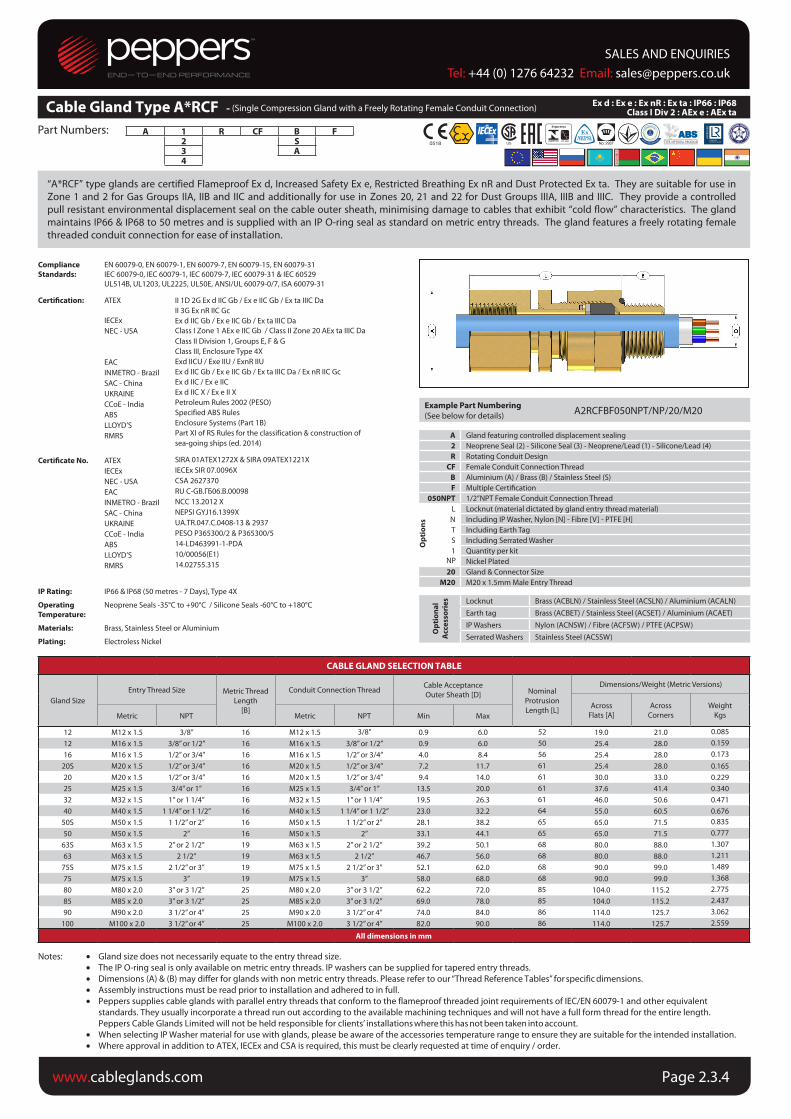
“A*RCF” type glands are certified Flameproof Ex d, Increased Safety Ex e, Restricted Breathing Ex nR and Dust Protected Ex ta. They are suitable for use in
Zone 1 and 2 for Gas Groups IIA, IIB and IIC and additionally for use in Zones 20, 21 and 22 for Dust Groups IIIA, IIIB and IIIC. They provide a controlled
pull resistant environmental displacement seal on the cable outer sheath, minimising damage to cables that exhibit “cold flow” characteristics. The gland
maintains IP66 & IP68 to 50 metres and is supplied with an IP O-ring seal as standard on metric entry threads. The gland features a freely rotating female
threaded conduit connection for ease of installation.
• Gland size does not necessarily equate to the entry thread size.
• The IP O-ring seal is only available on metric entry threads. IP washers can be supplied for tapered entry threads.
• Dimensions (A) & (B) may differ for glands with non metric entry threads. Please refer to our “Thread Reference Tables” for specific dimensions.
• Assembly instructions must be read prior to installation and adhered to in full.
• Peppers supplies cable glands with parallel entry threads that conform to the flameproof threaded joint requirements of IEC/EN 60079-1 and other equivalent
standards. They usually incorporate a thread run out according to the available machining techniques and will not have a full form thread for the entire length.
Peppers Cable Glands Limited will not be held responsible for clients’ installations where this has not been taken into account.
• When selecting IP Washer material for use with glands, please be aware of the accessories temperature range to ensure they are suitable for the intended installation.
• Where approval in addition to ATEX, IECEx and CSA is required, this must be clearly requested at time of enquiry / order.
A 1 R CF B F2 S3 A4
Compliance
Standards:
EN 60079-0, EN 60079-1, EN 60079-7, EN 60079-15, EN 60079-31
IEC 60079-0, IEC 60079-1, IEC 60079-7, IEC 60079-31 & IEC 60529
UL514B, UL1203, UL2225, UL50E, ANSI/UL 60079-0/7, ISA 60079-31
Certiication: ATEX
IECEx
NEC - USA
EAC
INMETRO - Brazil
SAC - China
UKRAINE
CCoE - India
ABS
LLOYD’S
RMRS
Certiicate No. ATEX
IECEx
NEC - USA
EAC
INMETRO - Brazil
SAC - China
UKRAINE
CCoE - India
ABS
LLOYD’S
RMRS
II 1D 2G Ex d IIC Gb / Ex e IIC Gb / Ex ta IIIC Da
II 3G Ex nR IIC Gc
Ex d IIC Gb / Ex e IIC Gb / Ex ta IIIC Da
Class I Zone 1 AEx e IIC Gb / Class II Zone 20 AEx ta IIIC Da Class II Division 1, Groups E, F & G
Class III, Enclosure Type 4X
Exd IICU / Exe IIU / ExnR IIU
Ex d IIC Gb / Ex e IIC Gb / Ex ta IIIC Da / Ex nR IIC Gc
Ex d IIC / Ex e IIC
Ex d IIC X / Ex e II X
Petroleum Rules 2002 (PESO)
Specified ABS Rules
Enclosure Systems (Part 1B)
Part XI of RS Rules for the classification & construction of
sea-going ships (ed. 2014)
SIRA 01ATEX1272X & SIRA 09ATEX1221X
IECEx SIR 07.0096X
CSA 2627370
RU C-GB.ГБ06.В.00098
NCC 13.2012 X
NEPSI GYJ16.1399X
UA.TR.047.C.0408-13 & 2937
PESO P365300/2 & P365300/5
14-LD463991-1-PDA
10/00056(E1)
14.02755.315
IP Rating:
Operating
Temperature:
Materials:
Plating:
IP66 & IP68 (50 metres - 7 Days), Type 4X
Neoprene Seals -35°C to +90°C / Silicone Seals -60°C to +180°C
Brass, Stainless Steel or Aluminium
Electroless Nickel
CABLE GLAND SELECTION TABLE
Gland Size
Entry Thread Size Metric Thread
Length
[B]
Conduit Connection ThreadCable Acceptance
Outer Sheath [D] Nominal
Protrusion
Length [L]
Dimensions/Weight (Metric Versions)
Across
Flats [A]
Across
Corners
Weight
KgsMetric NPT Metric NPT Min Max
12 M12 x 1.5 3/8” 16 M12 x 1.5 3/8" 0.9 6.0 52 19.0 21.0 0.08512 M16 x 1.5 3/8” or 1/2” 16 M16 x 1.5 3/8” or 1/2” 0.9 6.0 50 25.4 28.0 0.15916 M16 x 1.5 1/2” or 3/4” 16 M16 x 1.5 1/2” or 3/4” 4.0 8.4 56 25.4 28.0 0.173
20S M20 x 1.5 1/2” or 3/4” 16 M20 x 1.5 1/2” or 3/4” 7.2 11.7 61 25.4 28.0 0.16520 M20 x 1.5 1/2” or 3/4” 16 M20 x 1.5 1/2” or 3/4” 9.4 14.0 61 30.0 33.0 0.22925 M25 x 1.5 3/4” or 1” 16 M25 x 1.5 3/4” or 1” 13.5 20.0 61 37.6 41.4 0.34032 M32 x 1.5 1” or 1 1/4” 16 M32 x 1.5 1” or 1 1/4” 19.5 26.3 61 46.0 50.6 0.47140 M40 x 1.5 1 1/4” or 1 1/2” 16 M40 x 1.5 1 1/4” or 1 1/2” 23.0 32.2 64 55.0 60.5 0.676
50S M50 x 1.5 1 1/2” or 2” 16 M50 x 1.5 1 1/2” or 2” 28.1 38.2 65 65.0 71.5 0.83550 M50 x 1.5 2” 16 M50 x 1.5 2” 33.1 44.1 65 65.0 71.5 0.777
63S M63 x 1.5 2” or 2 1/2” 19 M63 x 1.5 2” or 2 1/2” 39.2 50.1 68 80.0 88.0 1.30763 M63 x 1.5 2 1/2” 19 M63 x 1.5 2 1/2” 46.7 56.0 68 80.0 88.0 1.211
75S M75 x 1.5 2 1/2” or 3” 19 M75 x 1.5 2 1/2” or 3” 52.1 62.0 68 90.0 99.0 1.48975 M75 x 1.5 3” 19 M75 x 1.5 3” 58.0 68.0 68 90.0 99.0 1.36880 M80 x 2.0 3” or 3 1/2” 25 M80 x 2.0 3” or 3 1/2” 62.2 72.0 85 104.0 115.2 2.77585 M85 x 2.0 3” or 3 1/2” 25 M85 x 2.0 3” or 3 1/2” 69.0 78.0 85 104.0 115.2 2.43790 M90 x 2.0 3 1/2” or 4” 25 M90 x 2.0 3 1/2” or 4” 74.0 84.0 86 114.0 125.7 3.062
100 M100 x 2.0 3 1/2” or 4” 25 M100 x 2.0 3 1/2” or 4” 82.0 90.0 86 114.0 125.7 2.559
All dimensions in mm
Example Part Numbering
(See below for details)A2RCFBF050NPT/NP/20/M20
A Gland featuring controlled displacement sealing
2 Neoprene Seal (2) - Silicone Seal (3) - Neoprene/Lead (1) - Silicone/Lead (4)
R Rotating Conduit Design
CF Female Conduit Connection Thread
B Aluminium (A) / Brass (B) / Stainless Steel (S)
F Multiple Certiication
050NPT 1/2”NPT Female Conduit Connection Thread
L Locknut (material dictated by gland entry thread material)
N Including IP Washer, Nylon [N] - Fibre [V] - PTFE [H]
T Including Earth Tag
S Including Serrated Washer
1 Quantity per kit
Nickel Plated
20 Gland & Connector Size
M20 M20 x 1.5mm Male Entry Thread
Op
tio
na
l
Acc
ess
ori
es Locknut Brass (ACBLN) / Stainless Steel (ACSLN) / Aluminium (ACALN)
Earth tag Brass (ACBET) / Stainless Steel (ACSET) / Aluminium (ACAET)
IP Washers Nylon (ACNSW) / Fibre (ACFSW) / PTFE (ACPSW)
Serrated Washers Stainless Steel (ACSSW)
Op
tio
ns
Cable Gland Type A*RCF - (Single Compression Gland with a Freely Rotating Female Conduit Connection)
NP
SALES AND ENQUIRIESTel: +44 (0) 1276 64232 Email: [email protected]
www.cableglands.com Page 2.3.4