Penetration of rigid objects into semi-infinite compressible solids
14
Penetration of rigid objects into semi-infinite compressible solids Amit Shaw Department of Civil Engg., Indian Institute of Technology, Kharagpur, India article info Article history: Received 12 August 2011 Received in revised form 30 January 2012 Available online 23 March 2012 Keywords: Semi-infinite target Rigid object Analytical model Smooth particle hydrodynamics Acceleration correction abstract Penetration of rigid object into semi-infinite compressible solid is investigated in the pres- ent study. First a detailed numerical analysis of the penetration process is performed via smooth particle hydrodynamics. Based on the numerical results, estimate for the resistive force that the target exerts on the penetrating object is obtained. It is shown that in the computation of the resistive force the quasi-static coefficient can accurately be obtained through the spherical cavity expansion theory. However for a given target material the coefficient associated with the hydro-dynamic term significantly depends on the impact velocity unlike commonly assumed constant values. Penetration equations for rigid object with arbitrary nose geometries are derived. Developed analytical model is then verified through some experimental and analytical results reported in the literature. Ó 2012 Elsevier Ltd. All rights reserved. 1. Introduction The mechanics of indentation and penetration (when depth is considerably larger than the characteristic dimen- sion of the indenter) of rigid object into thick target has been the subject of interest for many decades to both experimentalist and numerical analyst. Experimental work provides the highest accuracy but it has disadvantage of being valid exclusively for the material used in the exper- iment. Moreover experiments provide a cumulative effect of all involving parameters which are difficult to be iso- lated. Numerical simulations, on the other hand give de- tailed information which enables a better understanding of the penetration process. However it requires relatively large computational effort and thus may not be of much interest to design professionals and engineers. Finally, the third approach is the development of analytical model based on some simplified assumptions which are consis- tent with the physics of the process. Prediction via analyt- ical model is generally slightly less accurate compared to full numerical simulation. However requirement of little computational effort and ease of understanding of the ef- fect of each underlying parameters (geometric as well as material) make analytical model more useful and attrac- tive to design professionals. The first attempt towards the development of analytical method for penetration of rigid object may be traced back to the classical work by Bishop et al. (1945) who developed an expression for resistive force on a slowly penetrating rigid cone into an elasto- plastic solid. Their work was based on the theory of expan- sion of cylindrical and spherical cavities in an elasto-plastic incompressible solid. Based on dynamic spherical cavity expansion analysis Hopkins (1960) and Goodier (1965) derived the equations for rigid sphere penetrating into a soft target. Later Forrestal et al. (1988) developed closed form expression for final depth of penetration of a rigid long rod into a semi-infinite solid. The effect of nose geom- etries and friction at the rod-target interface were also con- sidered in their model. Some other work based on the dynamic cavity expansion analysis may be found in Dur- ban and Baruch (1976), Durban and Fleck (1992, 1997), Durban and Masri (2004), Masri and Durban (2005, 2006a,b, 2007, 2009) and Luk and Amos (1991). Based on a series of 2D numerical simulation Rosenberg and Dekel (2009) obtained the critical velocities for the cavitation process in a semi-infinite target for different rod-target pairs. Using this critical velocity they developed a closed form expression for final depth of penetration. 0167-6636/$ - see front matter Ó 2012 Elsevier Ltd. All rights reserved. http://dx.doi.org/10.1016/j.mechmat.2012.03.004 E-mail address: [email protected] Mechanics of Materials 50 (2012) 22–35 Contents lists available at SciVerse ScienceDirect Mechanics of Materials journal homepage: www.elsevier.com/locate/mechmat
Transcript of Penetration of rigid objects into semi-infinite compressible solids
Mechanics of Materials 50 (2012) 22–35
Contents lists available at SciVerse ScienceDirect
Mechanics of Materials
journal homepage: www.elsevier .com/locate /mechmat
Penetration of rigid objects into semi-infinite compressible solids
Amit ShawDepartment of Civil Engg., Indian Institute of Technology, Kharagpur, India
a r t i c l e i n f o
Article history:Received 12 August 2011Received in revised form 30 January 2012Available online 23 March 2012
Keywords:Semi-infinite targetRigid objectAnalytical modelSmooth particle hydrodynamicsAcceleration correction
0167-6636/$ - see front matter � 2012 Elsevier Ltdhttp://dx.doi.org/10.1016/j.mechmat.2012.03.004
E-mail address: [email protected]
a b s t r a c t
Penetration of rigid object into semi-infinite compressible solid is investigated in the pres-ent study. First a detailed numerical analysis of the penetration process is performed viasmooth particle hydrodynamics. Based on the numerical results, estimate for the resistiveforce that the target exerts on the penetrating object is obtained. It is shown that in thecomputation of the resistive force the quasi-static coefficient can accurately be obtainedthrough the spherical cavity expansion theory. However for a given target material thecoefficient associated with the hydro-dynamic term significantly depends on the impactvelocity unlike commonly assumed constant values. Penetration equations for rigid objectwith arbitrary nose geometries are derived. Developed analytical model is then verifiedthrough some experimental and analytical results reported in the literature.
� 2012 Elsevier Ltd. All rights reserved.
1. Introduction
The mechanics of indentation and penetration (whendepth is considerably larger than the characteristic dimen-sion of the indenter) of rigid object into thick target hasbeen the subject of interest for many decades to bothexperimentalist and numerical analyst. Experimental workprovides the highest accuracy but it has disadvantage ofbeing valid exclusively for the material used in the exper-iment. Moreover experiments provide a cumulative effectof all involving parameters which are difficult to be iso-lated. Numerical simulations, on the other hand give de-tailed information which enables a better understandingof the penetration process. However it requires relativelylarge computational effort and thus may not be of muchinterest to design professionals and engineers. Finally, thethird approach is the development of analytical modelbased on some simplified assumptions which are consis-tent with the physics of the process. Prediction via analyt-ical model is generally slightly less accurate compared tofull numerical simulation. However requirement of littlecomputational effort and ease of understanding of the ef-fect of each underlying parameters (geometric as well as
. All rights reserved.
material) make analytical model more useful and attrac-tive to design professionals. The first attempt towards thedevelopment of analytical method for penetration of rigidobject may be traced back to the classical work by Bishopet al. (1945) who developed an expression for resistiveforce on a slowly penetrating rigid cone into an elasto-plastic solid. Their work was based on the theory of expan-sion of cylindrical and spherical cavities in an elasto-plasticincompressible solid. Based on dynamic spherical cavityexpansion analysis Hopkins (1960) and Goodier (1965)derived the equations for rigid sphere penetrating into asoft target. Later Forrestal et al. (1988) developed closedform expression for final depth of penetration of a rigidlong rod into a semi-infinite solid. The effect of nose geom-etries and friction at the rod-target interface were also con-sidered in their model. Some other work based on thedynamic cavity expansion analysis may be found in Dur-ban and Baruch (1976), Durban and Fleck (1992, 1997),Durban and Masri (2004), Masri and Durban (2005,2006a,b, 2007, 2009) and Luk and Amos (1991). Based ona series of 2D numerical simulation Rosenberg and Dekel(2009) obtained the critical velocities for the cavitationprocess in a semi-infinite target for different rod-targetpairs. Using this critical velocity they developed a closedform expression for final depth of penetration.

(a)
(c)
D0
D0 D0 2φ
D0
s
(d)
(b)
Fig. 1. Objects with different nose geometry (a) flat; (b) ogival; (c)spherical; (d) conical.
Table 1Target material properties.
Targetmaterial
Density (qt)(kg/m3)
Young’smod (E)(GPa)
Poisson’sratio ()
Yieldstress(Y0)(GPa)
Aluminium-1 2710 68.9 0.33 0.4Aluminium-2 2710 68.9 0.33 0.8
A. Shaw / Mechanics of Materials 50 (2012) 22–35 23
In all analytical models based on the cavity expansionanalysis, the resistive force at the rod target interface is as-sumed to have a common generic form as,
F ¼ pD2
4ðAY0 þ bqtv2Þ; ð1Þ
where D is the rod diameter, v is the velocity (it is also thespeed at which penetration takes place) of the rod, Y0 andqt are respectively the yield stress and density of the targetmaterial. A and b are the parameters which depend on var-ious factors such as target material properties, nose geom-etry, friction at the rod-target interface etc. The accuracy ofprediction through any analytical model that uses Eq. (1)significantly depends on how accurately the parametersA and b are estimated. In the literature several attemptshave been made either through cavity expansion analysisor through 2D numerical simulation (Batra and Wright,1986) in order to estimate the parameters A and b. How-ever there exist considerable discrepancies among thosestudies (Rosenberg and Dekel, 2009).
In the present study first a numerical investigation ofthe penetration of rigid objects into semi-infinite com-pressible solid is performed. Based on the results throughnumerical simulations, estimates for parameters A and bare obtained. Finally analytical models for penetration ofrigid object with different nose geometries into semi-infi-nite compressible solid are derived. The developed modelis validated through some experimental and analyticalwork reported in the literature.
The paper is organized as follows. Numerical model isbriefly outlined in Section 2. Resistive force exerted by alu-minium target on the nose of a penetrating object is com-puted and detail estimate of the associated coefficients arediscussed in Section 3. Penetration equations for objectwith different nose geometries are derived in Section 4.In Section 5 the developed model is validated throughsome experimental, numerical and analytical resultsreported in the literature. Conclusions are drawn inSection 6.
2. Numerical model
In the present study numerical simulations are per-formed via the smoothed particle hydrodynamics (SPH)(Libersky et al., 1993). In SPH, the computational domain
Fig. 2. Discretization of the
is discretized by a set of particles which interact with eachother through a kernel function. Contact between two par-ticles establishes when one particle comes within theinfluence domain (which is defined by the support size ofthe kernel function) of other. Once the continuum equa-tions are discretized, the discrete SPH equations are up-dated in time. For comprehensive information about SPHone may refer to the review paper by Monaghan (2005)and the references therein. In order to reduce the adverseeffect (spurious reduction of kinetic energy of the system)of artificial viscosity (often used to stabilize the SPH com-putation) the acceleration correction algorithm as devel-oped by Shaw and Reid (2009a,b) and Shaw et al. (2011)is used.
Objects with four different nose geometries viz. flat,spherical, conical and ogival as shown in Fig. 1 are consid-ered in this study. Two different aluminium targets as gi-ven in Table 1 are considered. The target materials areassumed to be elastic-perfectly plastic and the flow régimeis determined by the Von Mises yield criterion. Young’s
domain by particles.
(a)
m, v0
z x
σn dA
μσn dAμσn dA
σn dA
m, v
z x
L
(b)
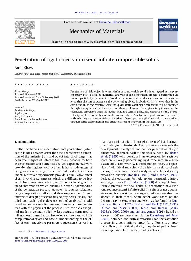
Fig. 3. Penetration of arbitrary shaped rigid object into semi-infinite target.
24 A. Shaw / Mechanics of Materials 50 (2012) 22–35
modulus and yield stress of the object is taken very highcompared to the target materials so that in numerical sim-ulation the object behaves as a rigid body. In order to mod-el the target as semi-infinite the computational domain forthe target is taken sufficiently large so that the reflectedwaves from the boundary do not affect the penetrationprocess. Penetrating object and the target are discretizedrespectively by 162 and 71064 particles as shown inFig. 2. For time integration the standard predictor–correc-tor scheme (Monaghan, 1989) with constant time step of0.01 ls is used.
m, v0
∞∞
∞
∞ ∞
∞
m, v(t)
Fz
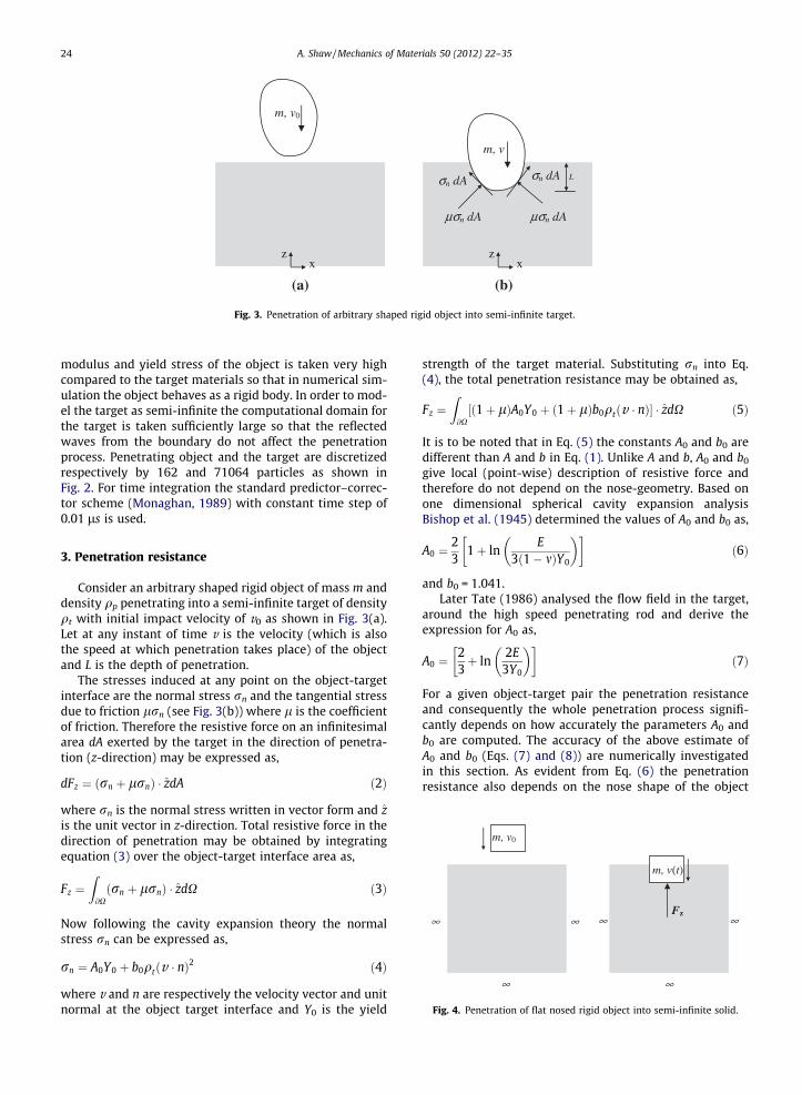
Fig. 4. Penetration of flat nosed rigid object into semi-infinite solid.
3. Penetration resistance
Consider an arbitrary shaped rigid object of mass m anddensity qp penetrating into a semi-infinite target of densityqt with initial impact velocity of v0 as shown in Fig. 3(a).Let at any instant of time v is the velocity (which is alsothe speed at which penetration takes place) of the objectand L is the depth of penetration.
The stresses induced at any point on the object-targetinterface are the normal stress rn and the tangential stressdue to friction lrn (see Fig. 3(b)) where l is the coefficientof friction. Therefore the resistive force on an infinitesimalarea dA exerted by the target in the direction of penetra-tion (z-direction) may be expressed as,
dFz ¼ ðrn þ lrnÞ � zdA ð2Þ
where rn is the normal stress written in vector form and zis the unit vector in z-direction. Total resistive force in thedirection of penetration may be obtained by integratingequation (3) over the object-target interface area as,
Fz ¼Z@Xðrn þ lrnÞ � zdX ð3Þ
Now following the cavity expansion theory the normalstress rn can be expressed as,
rn ¼ A0Y0 þ b0qtðv � nÞ2 ð4Þ
where v and n are respectively the velocity vector and unitnormal at the object target interface and Y0 is the yield
strength of the target material. Substituting rn into Eq.(4), the total penetration resistance may be obtained as,
Fz ¼Z@X½ð1þ lÞA0Y0 þ ð1þ lÞb0qtðv � nÞ� � zdX ð5Þ
It is to be noted that in Eq. (5) the constants A0 and b0 aredifferent than A and b in Eq. (1). Unlike A and b, A0 and b0
give local (point-wise) description of resistive force andtherefore do not depend on the nose-geometry. Based onone dimensional spherical cavity expansion analysisBishop et al. (1945) determined the values of A0 and b0 as,
A0 ¼23
1þ lnE
3ð1� mÞY0
� �� �ð6Þ
and b0 = 1.041.Later Tate (1986) analysed the flow field in the target,
around the high speed penetrating rod and derive theexpression for A0 as,
A0 ¼23þ ln
2E3Y0
� �� �ð7Þ
For a given object-target pair the penetration resistanceand consequently the whole penetration process signifi-cantly depends on how accurately the parameters A0 andb0 are computed. The accuracy of the above estimate ofA0 and b0 (Eqs. (7) and (8)) are numerically investigatedin this section. As evident from Eq. (6) the penetrationresistance also depends on the nose shape of the object
A. Shaw / Mechanics of Materials 50 (2012) 22–35 25
and the frictional coefficient at the object-target interface.In order to decouple these effects from that of A0 and b0
first the penetration of a flat-nosed rigid cylindrical objectas shown in Fig. 4 is considered. Since the interface area isnormal to the direction of penetration, frictional force doesnot contribute anything to Fz.
Removing the frictional term from Eq. (6), the resistiveforce Fz for a flat-nosed object may be written as,
Fz ¼ pD2
4rn ð8Þ
Substituting rn from Eq. (5), Fz may be written as,
Fz ¼ pD2
4ðA0Y0 þ b0qtv2Þ ð9Þ
0 10 20 30 40 50-3.5
-3
-2.5
-2
-1.5
-1
-0.5
0x 10
8
Time (mi
Acc
eler
atio
n (m
/s2 )
0 10 20 30-3.5
-3
-2.5
-2
-1.5
-1
-0.5
0x 10
8
Time (mic
Acc
eler
atio
n (m
/s2 )
(a)
(b)
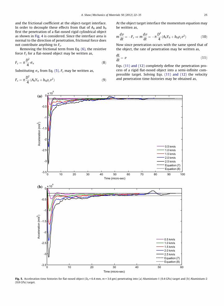
Fig. 5. Acceleration time histories for flat-nosed object (D0 = 6.4 mm, m = 3.6 gm(0.8 GPa) target.
At the object target interface the momentum equation maybe written as,
mdvdt¼ �Fz ) m
dvdt¼ �pD2
4ðA0Y0 þ b0qtv2Þ ð10Þ
Now since penetration occurs with the same speed that ofthe object, the rate of penetration may be written as,
dLdt¼ v ð11Þ
Eqs. (11) and (12) completely define the penetration pro-cess of a rigid flat-nosed object into a semi-infinite com-pressible target. Solving Eqs. (11) and (12) the velocityand penetration time-histories may be obtained as,
60 70 80 90 100cro-sec)
0.5 km/s1.0 km/s1.5 km/s2.0 km/s2.5 km/sEquation (7)Equation (8)
40 50 60ro-sec)
0.5 km/s1.0 km/s1.5 km/s2.0 km/s2.5 km/sEquation (7)Equation (8)
) penetrating into (a) Aluminium-1 (0.4 GPa) target and (b) Aluminium
-2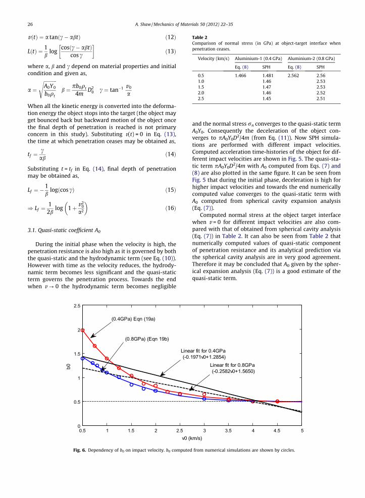
Table 2Comparison of normal stress (in GPa) at object-target interface whenpenetration ceases.
Velocity (km/s) Aluminium-1 (0.4 GPa) Aluminium-2 (0.8 GPa)
Eq. (8) SPH Eq. (8) SPH
0.5 1.466 1.481 2.562 2.561.0 1.46 2.531.5 1.47 2.532.0 1.46 2.522.5 1.45 2.51
26 A. Shaw / Mechanics of Materials 50 (2012) 22–35
vðtÞ ¼ a tanðc� abtÞ ð12Þ
LðtÞ ¼ 1b
logcosðc� abtÞ
cos c
� �ð13Þ
where a, b and c depend on material properties and initialcondition and given as,
a ¼ffiffiffiffiffiffiffiffiffiffiffiA0Y0
b0qt
sb ¼ pb0qt
4mD2
0 c ¼ tan�1 v0
a
When all the kinetic energy is converted into the deforma-tion energy the object stops into the target (the object mayget bounced back but backward motion of the object oncethe final depth of penetration is reached is not primaryconcern in this study). Substituting v(t) = 0 in Eq. (13),the time at which penetration ceases may be obtained as,
tf ¼cab
ð14Þ
Substituting t = tf in Eq. (14), final depth of penetrationmay be obtained as,
Lf ¼ �1b
logðcos cÞ ð15Þ
) Lf ¼1
2blog 1þ v2
0
a2
� �ð16Þ
3.1. Quasi-static coefficient A0
During the initial phase when the velocity is high, thepenetration resistance is also high as it is governed by boththe quasi-static and the hydrodynamic term (see Eq. (10)).However with time as the velocity reduces, the hydrody-namic term becomes less significant and the quasi-staticterm governs the penetration process. Towards the endwhen v ? 0 the hydrodynamic term becomes negligible
0.5 1 1.5 2 2.50
0.5
1
1.5
2
2.5
v0 (k
b0
(0.4GPa) Eqn (19a)
Line (-0.
(0.8GPa) (Eqn 19b)
Fig. 6. Dependency of b0 on impact velocity. b0 computed
and the normal stress rn converges to the quasi-static termA0Y0. Consequently the deceleration of the object con-verges to pA0Y0D2/4m (from Eq. (11)). Now SPH simula-tions are performed with different impact velocities.Computed acceleration time-histories of the object for dif-ferent impact velocities are shown in Fig. 5. The quasi-sta-tic term pA0Y0D2/4m with A0 computed from Eqs. (7) and(8) are also plotted in the same figure. It can be seen fromFig. 5 that during the initial phase, deceleration is high forhigher impact velocities and towards the end numericallycomputed value converges to the quasi-static term withA0 computed from spherical cavity expansion analysis(Eq. (7)).
Computed normal stress at the object target interfacewhen v = 0 for different impact velocities are also com-pared with that of obtained from spherical cavity analysis(Eq. (7)) in Table 2. It can also be seen from Table 2 thatnumerically computed values of quasi-static componentof penetration resistance and its analytical prediction viathe spherical cavity analysis are in very good agreement.Therefore it may be concluded that A0 given by the spher-ical expansion analysis (Eq. (7)) is a good estimate of thequasi-static term.
3 3.5 4 4.5 5m/s)
ar fit for 0.4GPa1971v0+1.2854)
Linear fit for 0.8GPa (-0.2582v0+1.5650)
from numerical simulations are shown by circles.
0 0.1 0.2 0.3 0.4 0.50
2
4
6
8
10
12
14
16
18
v/c
Pen
etra
tion
resi
stan
ce (G
Pa)
MD modelProposed model with quartic b0Proposed model with linear b0
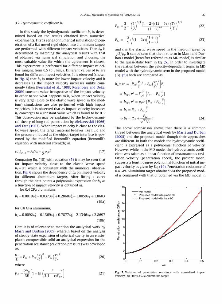
Fig. 7. Variation of penetration resistance with normalized impactvelocity (v/c) for 0.4 GPa Aluminium target.
A. Shaw / Mechanics of Materials 50 (2012) 22–35 27
3.2. Hydrodynamic coefficient b0
In this study the hydrodynamic coefficient b0 is deter-mined based on the results obtained from numericalexperiments. First a series of numerical simulations of pen-etration of a flat nosed rigid object into aluminium targetsare performed with different impact velocities. Then b0 isdetermined by matching the analytical results with thatof obtained via numerical simulation and choosing themost suitable value for which the agreement is closest.This experiment is performed for different impact veloci-ties ranging from 0.5 to 3 km/s. Different values of b0 arefound for different impact velocities. It is observed (shownin Fig. 6) that b0 is more for lower impact velocity and itdecreases as the impact velocity increases unlike com-monly taken (Forrestal et al., 1988; Rosenberg and Dekel2009) constant value irrespective of the impact velocity.In order to see what happens to b0 when impact velocityis very large (close to the elastic wave speed in the med-ium) simulations are also performed with high impactvelocities. It is observed that as impact velocity increasesb0 converges to a constant value which is found to be 0.5.This observation may be explained by the hydro-dynami-cal theory of long rod penetration by Alekseevskii (1966)and Tate (1967). When impact velocity is close to the elas-tic wave speed, the target material behaves like fluid andthe pressure induced at the object-target interface is gov-erned by the modified Bernoulli’s equation (Bernoulli’sequation with material strength) as,
ðrzÞv!c ¼ A0Y0 þ12qtv2 ð17Þ
Comparing Eq. (18) with equation (5) it may be seen thatfor impact velocity close to the elastic wave speedb0 = 0.5 which is consistent with the numerical observa-tion. Fig. 6 shows the dependency of b0 on impact velocityfor different aluminium targets. After fitting a curvethrough the data points a polynomial expression for b0 asa function of impact velocity is obtained as,
for 0.4 GPa aluminium,
b0¼0:0019v40�0:0373v3
0þ0:2860v20�1:0059v0þ1:8603
ð19aÞ
for 0.8 GPa aluminium,
b0¼0:0092v40�0:1369v3
0þ0:7877v20�2:1346v0þ2:8697
ð19bÞ
Here it is of relevance to mention the analytical work byMasri and Durban (2005) wherein based on the analysisof steady-state expansion of spherical cavity in an elasto-plastic compressible solid an analytical expression for thepenetration resistance (cavitation pressure) was developedas,
rz
E¼ Pc0 þ Pc1
vc
� �2þ Pc2
vc
� �3ð20Þ
where
Pc0 ¼2Y0
3E1þ ln
E3ð1� mÞY0
� �� �ð21Þ
Pc1 ¼32� 1
3
� �5=3 ð1� 2mÞð13� 5mÞð1� mÞ5=3
Y0
E
� �1=3
ð22Þ
Pc2 ¼ �29
ffiffiffiffiffiffiffiffiffiffiffiffiffiffiffiffiffiffiffiffiffiffiffiffiffiffiffiffiffiffiffiffiffiffiffiffiffiffiffið1� 2mÞ 1þ m
1� m
� �5s
ð23Þ
and c is the elastic wave speed in the medium given byffiffiffiffiffiffiffiffiffiffiE=qt
p. It can be seen that the first term in Masri and Dur-
ban’s model (hereafter referred to as MD model) is similarto the quasi-static term in Eq. (5). In order to investigatethe relation between the velocity-dependent terms in MDmodel with the hydrodynamic term in the proposed model(Eq. (5)) both are compared as,
b0qtv2 ¼ Pc1ðvcÞ2 þ Pc2
vc
� �3� �
E
) b0qtv2 ¼ Ev2
c2 Pc1 þ Pc2vc
� �) b0qtv2 ¼ qtv2 Pc1 þ Pc2
vc
� �) b0 ¼ Pc1 þ Pc2
vc
) b0 ¼ Pc1 þPc2ffiffiffiffiffiffiffiffiffiffiE=qt
p v ð24Þ
The above comparison shows that there is a commonthread between the analytical work by Masri and Durban(2005) and the proposed model though their approachesare different. In both the models the hydrodynamic coeffi-cient is expressed as a polynomial function of velocity.However while in the MD model the hydrodynamic coeffi-cient was taken as a linear function of instantaneous cavi-tation velocity (penetration speed), the present modelsuggests a fourth degree polynomial function of initial im-pact velocity as given by Eq. (19). Penetration resistance of0.4 GPa Aluminium target obtained via the proposed mod-el is compared with that of obtained via the MD model in
0 5 10 15 20 25 30 35 40 45 50 550
250
500
750
1000
Time (micro-sec)
Vel
ocity
(m/s
)SPHAnalytical
0 5 10 15 20 25 30 35 40 45 50 550
5
10
15
20
25
Time (micro-sec)
Dep
th o
f pen
etra
tion
(mm
)
SPHAnalytical
0 5 10 15 20 25 30 35 40 45 50 55 60 65 700
250
500
750
1000
1250
1500
Time (micro-sec)
Vel
ocity
(m/s
)
SPHAnalytical
0 5 10 15 20 25 30 35 40 45 50 55 60 65 700
5
10
15
20
25
30
35
40
Time (micro-sec)
Dep
th o
f pen
etra
tion
(mm
)
SPHAnalytical
0 5 10 15 20 25 30 35 40 45 50 55 60 65 70 75 800
250
500
750
1000
1250
1500
1750
2000
Time (micro-sec)
Vel
ocity
(m/s
)
SPHAnalytical
0 5 10 15 20 25 30 35 40 45 50 55 60 65 70 75 800
10
20
30
40
50
60
Time (micro-sec)
Dep
th o
f pen
etra
tion
(mm
)
SPHAnalytical
(a)
(b)
(c)
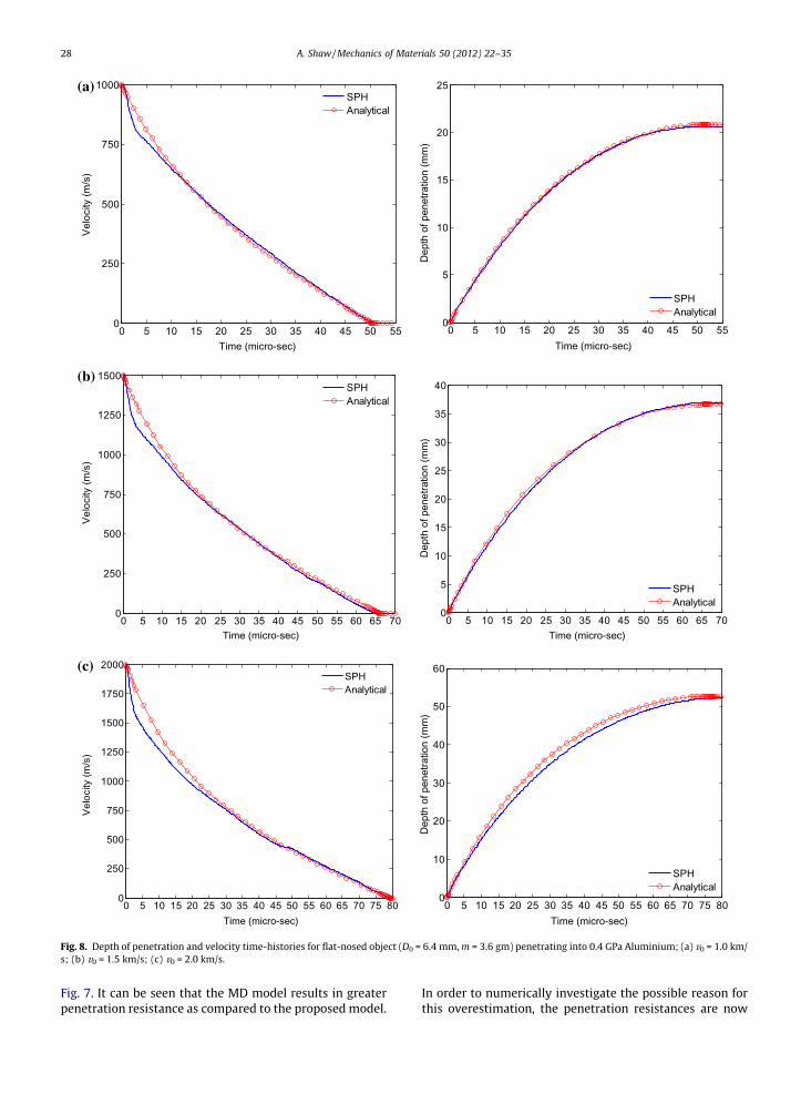
Fig. 8. Depth of penetration and velocity time-histories for flat-nosed object (D0 = 6.4 mm, m = 3.6 gm) penetrating into 0.4 GPa Aluminium; (a) v0 = 1.0 km/s; (b) v0 = 1.5 km/s; (c) v0 = 2.0 km/s.
28 A. Shaw / Mechanics of Materials 50 (2012) 22–35
Fig. 7. It can be seen that the MD model results in greaterpenetration resistance as compared to the proposed model.
In order to numerically investigate the possible reason forthis overestimation, the penetration resistances are now

0 5 10 15 20 25 30 350
250
500
750
1000
Time (micro-sec)
v(t)
(m/s
)
SPHAnalytical
0 5 10 15 20 25 30 350
2
4
6
8
10
12
14
Time (micro-sec)
Dep
th o
f pen
etra
tion
(mm
)
SPHAnalytical
0 5 10 15 20 25 30 35 40 450
250
500
750
1000
1250
1500
Time (micro-sec)
v(t)
(m/s
)
SPHAnalytical
0 5 10 15 20 25 30 35 40 450
5
10
15
20
25
Time (micro-sec)
Dep
th o
f pen
etra
tion
(mm
)
SPHAnalytical
0 5 10 15 20 25 30 35 40 45 50 550
250
500
750
1000
1250
1500
1750
2000
Time (micro-sec)
v(t)
(m/s
)
SPHAnalytical
0 5 10 15 20 25 30 35 40 45 50 550
5
10
15
20
25
30
35
40
Time (micro-sec)
Dep
th o
f pen
etra
tion
(mm
)
SPHAnalytical
(a)
(b)
(c)
Fig. 9. Depth of penetration and velocity time-histories for flat-nosed object (D0 = 6.4 mm, m = 3.6 gm) penetrating into 0.8 GPa Aluminium; (a) v0 = 1.0 km/s; (b) v0 = 1.5 km/s; (c) v0 = 2.0 km/s.
A. Shaw / Mechanics of Materials 50 (2012) 22–35 29
computed with a linear best fit for b0 (see Fig. 6) andcompared with MD model in the same figure. This time it
is observed that computed penetration resistances withlinear best fit for b0 and that of obtained via the MD model
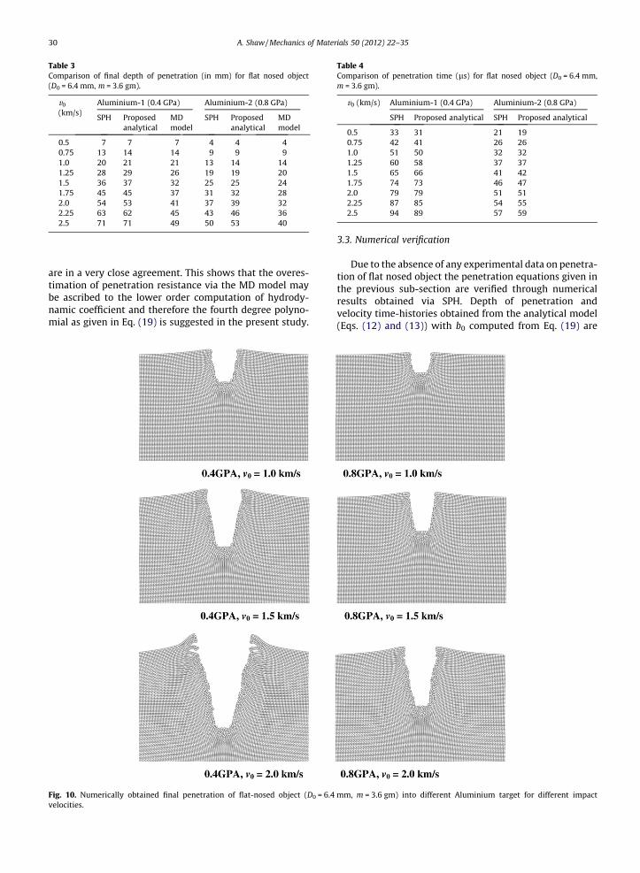
Table 3Comparison of final depth of penetration (in mm) for flat nosed object(D0 = 6.4 mm, m = 3.6 gm).
v0
(km/s)Aluminium-1 (0.4 GPa) Aluminium-2 (0.8 GPa)
SPH Proposedanalytical
MDmodel
SPH Proposedanalytical
MDmodel
0.5 7 7 7 4 4 40.75 13 14 14 9 9 91.0 20 21 21 13 14 141.25 28 29 26 19 19 201.5 36 37 32 25 25 241.75 45 45 37 31 32 282.0 54 53 41 37 39 322.25 63 62 45 43 46 362.5 71 71 49 50 53 40
Table 4Comparison of penetration time (ls) for flat nosed object (D0 = 6.4 mm,m = 3.6 gm).
v0 (km/s) Aluminium-1 (0.4 GPa) Aluminium-2 (0.8 GPa)
SPH Proposed analytical SPH Proposed analytical
0.5 33 31 21 190.75 42 41 26 261.0 51 50 32 321.25 60 58 37 371.5 65 66 41 421.75 74 73 46 472.0 79 79 51 512.25 87 85 54 552.5 94 89 57 59
30 A. Shaw / Mechanics of Materials 50 (2012) 22–35
are in a very close agreement. This shows that the overes-timation of penetration resistance via the MD model maybe ascribed to the lower order computation of hydrody-namic coefficient and therefore the fourth degree polyno-mial as given in Eq. (19) is suggested in the present study.
Fig. 10. Numerically obtained final penetration of flat-nosed object (D0 = 6.4velocities.
3.3. Numerical verification
Due to the absence of any experimental data on penetra-tion of flat nosed object the penetration equations given inthe previous sub-section are verified through numericalresults obtained via SPH. Depth of penetration andvelocity time-histories obtained from the analytical model(Eqs. (12) and (13)) with b0 computed from Eq. (19) are
mm, m = 3.6 gm) into different Aluminium target for different impact
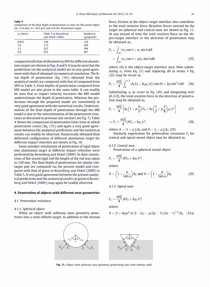
Table 5Comparison of the final depth of penetration (in mm) for flat-nosed object(D0 = 6.4 mm, m = 30.3 gm) into 0.4 GPa Aluminium target.
v0 (km/s) Table 5 in Rosenbergand Dekel (2009)
Analytical(proposed)
0.875 140 1391.0 175 1691.5 327 3092.0 472 467
A. Shaw / Mechanics of Materials 50 (2012) 22–35 31
compared with that of obtained via SPH for different alumin-ium targets are shown in Figs. 8 and 9. It may be seen that thepredictions via the analytical model are in very good agree-ment with that of obtained via numerical simulation. The fi-nal depth of penetration (Eq. (16)) obtained from theanalytical model are compared with that of computed fromSPH in Table 3. Final depths of penetration computed fromMD model are also given in the same table. It can readilybe seen that as impact velocity increases the MD modelunderestimate the depth of penetration. Whereas the pre-dictions through the proposed model are consistently invery good agreement with the numerical results. Underesti-mation of the final depth of penetration through the MDmodel is due to the overestimation of the penetration resis-tance as discussed in previous sub-section (see Fig. 7). Table4 shows the comparison of penetration time (time at whichpenetration ceases (Eq. (15)) and again a very good agree-ment between the analytical predictions and the numericalresults can readily be observed. Numerically obtained finaldeformed configuration of different aluminium target fordifferent impact velocities are shown in Fig. 10.
Some autodyn simulations of penetration of rigid objectinto aluminium target at different impact velocities wereperformed by Rosenberg and Dekel (2009). In their simula-tions of flat-nosed rigid rod the length of the rod was takenas 120 mm. The final depth of penetrations for similar rod-target pair are computed via the present model and com-pared with that of given in Rosenberg and Dekel (2009) inTable 5. A very good agreement between the present analyt-ical predictions and the numerical results (as given in Rosen-berg and Dekel (2009)) may again be readily observed.
4. Penetration of objects with different nose geometries
4.1. Penetration resistance
4.1.1. Spherical objectWhen an object with arbitrary nose geometry pene-
trates into a semi-infinite target, in addition to the normal
v
FnFtFn Ft
vθ vθϕ ϕ
Fig. 11. Object with arbitrary nose geometr
force, friction at the object-target interface also contributeto the total resistive force. Resistive forces exerted by thetarget on spherical and conical nose are shown in Fig. 11.At any instant of time the total resistive force on the ob-ject-target interface in the direction of penetration maybe obtained as,
Fz ¼Z@Xðrn cos hþ rt sin hÞdA
¼Z@Xðrn cos hþ lrn sin hÞdA ð25Þ
where oX is the object-target interface area. Now substi-tuting rn from Eq. (5) and replacing dA in terms h Eq.(25) may be recast as,
Fz ¼pD2
0
4
Z p=2
0ðA0Y0 þ b0qtv2
hÞðsin 2hþ 2l sin2 hÞdh ð26Þ
Substituting vh as vcosh in Eq. (26) and integrating over[0,p/2], the total resistive force in the direction of penetra-tion may be obtained as,
Fz ¼pD2
0
4A0 1þ lp
2
� �Y0 þ b0
12þ lp
8
� �qtv2
� �ð27Þ
) Fz ¼pD2
0
4½AY0 þ bqtv2� ð28Þ
where A ¼ ð1þ lp2ÞA0 and b ¼ ð12þ lp
8Þb0 (29)Similarly expressions for penetration resistance Fz for
conical and ogival nosed object may be obtained as,
4.1.2. Conical nosePenetration of a spherical nosed object
Fz ¼pD2
0
4½AY0 þ bqtv2�
where
A ¼ 1þ ltan /
� �A0 and b ¼ 1þ l
tan /
� �b0 ð29Þ
4.1.3. Ogival nose
Fz ¼pD2
0
4½AY0 þ bqtv2�
where
A ¼ ½1þ 4lw2ðp=2� h0Þ � lð2w� 1Þð2w� 1Þ1=2�A0 ð31aÞ
Ft Ft
FnFn
vθ vθθ θ
y penetrating into semi-infinite solid.

Table 6Comparison of depth of penetration (in mm) for spherical nose objects(D0 = 7.1 mm, l = 0.125) into 0.4 GPa Aluminium target.
Mass(gm)
v0
(km/s)Experimental(Forrestalet al., 1988)
AnalyticalRosenbergand Dekel
Analytical(proposed)
23.3 0.45 30 26 30
32 A. Shaw / Mechanics of Materials 50 (2012) 22–35
b ¼ 124w2 ½ð8w� 1Þ þ 24lw4ðp=2� h0Þ � lð2w� 1Þ
� ð6w2 þ 4w� 1Þð4w� 1Þ1=2�b0 ð31bÞ
w ¼ s2a
and h0 ¼ sin�1 2w� 12w
� �
23.3 0.76 72 75 7523.3 0.96 115 119 11123.3 1.12 152 162 14323.3 1.16 159 174 15123.7 0.48 36 30 3524.0 0.77 84 79 8023.7 1.0 119 132 121Table 7Comparison of depth of penetration (in mm) for conical nose (D0 = 7.1 mm,/ = 18.352�, l = 0.1) object into 0.4 GPa Aluminium target.
Mass(gm)
v0
(m/s)Experimental(Forrestalet al., 1988)
AnalyticalRosenbergand Dekel
Analytical(proposed)
23.8 510 40 40 4123.7 660 66 67 6823.6 940 121 135 13223.7 1000 145 154 14924.1 1060 153 176 16924.1 1150 196 207 19723.7 1370 273 289 270
Table 8Comparison of depth of penetration (in mm) for ogival nose (D0 = 7.1 mm,s = 21.3 mm, l = 0.04) into 0.4 GPa Aluminium target.
Mass(gm)
v0
(m/s)Experimental(Forrestalet al., 1988)
AnalyticalRosenbergand Dekel
Analytical(proposed)
24.9 440 44 32 3424.9 730 94 89 9024.7 790 105 104 10524.7 1000 163 166 16424.7 1260 253 264 25124.8 1460 333 355 331
4.2. Penetration equation
Similar to the flat-nosed object (see section 3.1) pene-tration equation for any object with arbitrary nose geome-try may be written as,
mdvdt¼ �pD2
0
4ðAY0 þ bqtv2Þ ð32Þ
dLdt¼ v ð33Þ
Coefficients A and b may be obtained depending on thenose shape as given in previous sub-section. Integratingequation (32) and (33) in time, expressions for time histo-ries and final depth of penetration may be obtained as,
vðtÞ ¼ a tanðc� abtÞ ð34Þ
LðtÞ ¼ 1b
logcosðc� abtÞ
cos c
� �ð35Þ
Lf ¼1
2blog 1þ v2
0
a2
� �ð36Þ
where
a ¼ffiffiffiffiffiffiffiffiffiAY0
bqt
sb ¼ pbqt
4mD2
0 c ¼ tan�1 v0
að37Þ
Coefficients A0 and b0 (required to compute A and b respec-tively) may be obtained as discussed in Sections 3.1 and 3.2respectively.
Before the proposed model is validated in the subse-quent section it is of relevance to mention the recent workby Cohen et al. (2010) on the formation of shock waves indynamic cavity expansion. Therein it was shown that forhigher expansion velocity a new plastic shock waveemerges which has to be taken into account. In the presentstudy the penetrating object is assumed to remain unde-formed throughout the penetration process. Experiments(Forrestal et al., 1988; Piekutowski et al., 1999) on penetra-tion of Aluminium targets show a visible deformation inthe penetrating rod if the impact velocity is high (generallyv/c > 0.4). Therefore the application of the proposed modelis restricted to v/c < 0.4. Since within this velocity rangeformation of the plastic shock wave does not take place,this is not accounted in the proposed model.
5. Verification of the analytical model
The analytical model derived in the previous section isvalidated through the experimental results reported byForrestal et al. (1988). The efficacy of the present modelis also demonstrated by comparing the computed results
with the analytical model developed by Rosenberg and De-kel (2009).
The final depth of penetration predicted via the presentmodel for object with different masses, nose geometriesand impact velocities are compared with the experimentalresults in Tables 6–8. Predictions via the analytical modeldeveloped by Rosenberg and Dekel (2009) are also givenin the same table. It can be observed that the final depthsof penetration obtained via the Rosenberg–Dekel modelare slightly on the higher side especially when the impactvelocity is more. On the other hand, predictions via thepresent model based on the velocity dependent b0 (Eq.(19)) are consistently close to the experimental results.
As discussed in Section 3 the distinct feature of thepresent model compared to its existing counterpart is theaccurate computation of the hydro-dynamic coefficient b0
as a function of impact velocity (see Eq. (19)). The effectof hydro-dynamic term becomes more significant for
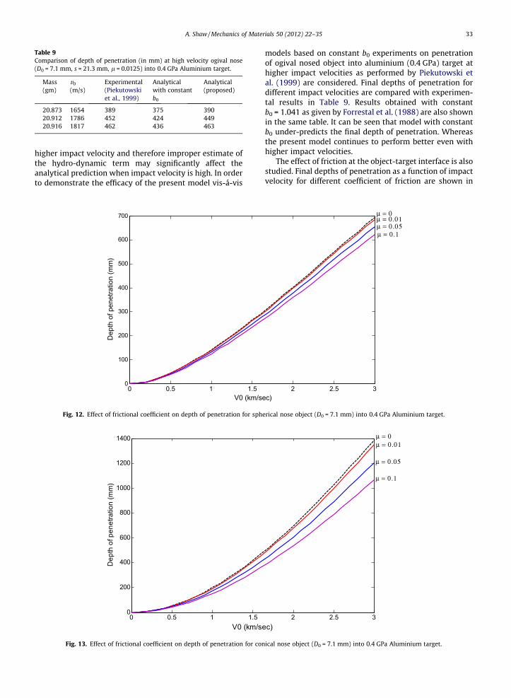
Table 9Comparison of depth of penetration (in mm) at high velocity ogival nose(D0 = 7.1 mm, s = 21.3 mm, l = 0.0125) into 0.4 GPa Aluminium target.
Mass(gm)
v0
(m/s)Experimental(Piekutowskiet al., 1999)
Analyticalwith constantb0
Analytical(proposed)
20.873 1654 389 375 39020.912 1786 452 424 44920.916 1817 462 436 463
A. Shaw / Mechanics of Materials 50 (2012) 22–35 33
higher impact velocity and therefore improper estimate ofthe hydro-dynamic term may significantly affect theanalytical prediction when impact velocity is high. In orderto demonstrate the efficacy of the present model vis-á-vis
0 0.5 1 1.50
100
200
300
400
500
600
700
V0 (km/se
Dep
th o
f pen
etra
tion
(mm
)
Fig. 12. Effect of frictional coefficient on depth of penetration for sph
0 0.5 1 1.50
200
400
600
800
1000
1200
1400
V0 (km/se
Dep
th o
f pen
etra
tion
(mm
)
Fig. 13. Effect of frictional coefficient on depth of penetration for con
models based on constant b0 experiments on penetrationof ogival nosed object into aluminium (0.4 GPa) target athigher impact velocities as performed by Piekutowski etal. (1999) are considered. Final depths of penetration fordifferent impact velocities are compared with experimen-tal results in Table 9. Results obtained with constantb0 = 1.041 as given by Forrestal et al. (1988) are also shownin the same table. It can be seen that model with constantb0 under-predicts the final depth of penetration. Whereasthe present model continues to perform better even withhigher impact velocities.
The effect of friction at the object-target interface is alsostudied. Final depths of penetration as a function of impactvelocity for different coefficient of friction are shown in
2 2.5 3c)
μ = 0.1μ = 0.05μ = 0.01μ = 0
erical nose object (D0 = 7.1 mm) into 0.4 GPa Aluminium target.
2 2.5 3c)
μ = 0
μ = 0.1
μ = 0.05
μ = 0.01
ical nose object (D0 = 7.1 mm) into 0.4 GPa Aluminium target.

0 0.5 1 1.5 2 2.5 30
200
400
600
800
1000
1200
1400
V0 (km/sec)
Dep
th o
f pen
etra
tion
(mm
)μ = 0.1
μ = 0.05
μ = 0.01μ = 0
Fig. 14. Effect of frictional coefficient on depth of penetration for ogival object (D0 = 7.1 mm) into 0.4 GPa Aluminium target.
34 A. Shaw / Mechanics of Materials 50 (2012) 22–35
Figs. 12–14. It is observed that the sensitivity of the predic-tion on the coefficient of friction is maximum for objectwith ogival nose and minimum for object with sphericalnose. This is consistent with the observation by Forrestalet al. (1988).
6. Closure
An analytical and numerical investigation of penetrationof rigid object into semi-infinite compressible solid is per-formed in this study. For numerical modelling an SPH basedhydro-code with acceleration correction algorithm (Shawand Reid, 2009a,b) is used. Through several numerical simu-lation it is shown that while the quasi-static coefficient A0
can be accurately computed through the spherical cavityexpansion theory as given by Bishop et al. (1945) its hy-dro-dynamic counterpart needs special attention. It is ob-served that the hydro-dynamic coefficient b0 significantlydepends on the impact velocity in addition to the targetmaterial properties. b0 decreases with increase in impactvelocity and converges to a constant value of 0.5 when im-pact velocity is very large (close to the elastic wave speedin the medium). Based on numerical simulations, expres-sions for b0 as a function of impact velocity for differentaluminium targets are obtained. Penetration equations forrigid object with arbitrary nose geometries are derived.Developed analytical model are then verified through exper-imental results reported by Forrestal et al. (1988), and Pieku-towski et al. (1999). The efficacy of the present model is alsodemonstrated via some other commonly used analyticalmodel based on constant hydro-dynamic coefficient. It isshown that analytical model based on constant hydro-dynamic coefficient may over-predict or under-predict thefinal depth of penetration depending on the impact velocity.However predictions via the present model where b0 is con-sidered as a function of impact velocity are in very goodagreement with the experimental results. The effect of
friction at the object-target interface is also studied. It is ob-served that the sensitivity of the prediction on the coeffi-cient of friction is maximum for object with ogival noseand minimum for object with spherical nose.
References
Alekseevskii, V.P., 1966, Penetration of a Rod into a Target at HighVelocity, Combustion explosion and Shock Waves, vol. 2, Springer,New York, USA.
Batra, R.C., Wright, T.W., 1986. Steady state penetration of rigid perfectlyplastic targets. Int. J. Eng. Sci. 24, 41.
Bishop, R.F., Hill, R., Mott, N.F., 1945. The theory of indentation andhardness. Proc. Roy. Soc. 57, 147.
Cohen, T., Masri, R., Durban, D., 2010. Shock waves in dynamic cavityexpansion. J. Appl. Mech. 77, 041009-1.
Durban, D., Baruch, M., 1976. On the problem of a spherical cavity in aninfinite elastoplastic medium. J. Appl. Mech. 43, 633–638.
Durban, D., Fleck, N.A., 1992. Singular plastic fields in steady penetrationof a rigid cone. J. Appl. Mech. (ASME Trans.) 59, 706–710.
Durban, D., Fleck, N.A., 1997. Spherical cavity expansion in a Drucker–Prager solid. J. Appl. Mech. 64, 743–750.
Durban, D., Masri, R., 2004. Dynamic spherical cavity expansion inpressure-sensitive elastoplastic medium. Int. J. Solids Struct. 41,5697–5716.
Forrestal, M.J., Okajima, K., Luk, V.K., 1988. Penetration of 6061-T651aluminum targets with rigid long rods. J. Appl. Mech. 55, 755–760.
Goodier, J.N. 1965. On the mechanics of indentation and cratering in solidtargets of strain hardening metal by impact of hard and soft spheres.In: Proceedings of the Seventh Symposium on Hypervelocity Impact,III, 215.
Hopkins, H.G., 1960. Dynamic expansion of spherical cavities in metals.In: Sneddon, I.N., Hill, R. (Eds.), Progress in Solid Mechanics, vol. 1.North-Holland Pub. Co..
Libersky, L.D., Petschek, A.G., Carney, T.C., Hipp, J.R., Allahdadi, F.A., 1993.High strain Lagrangian hydrodynamics a three-dimensional SPH codefor dynamic material response. J. Comput. Phys. 109, 67–75.
Luk, V.K., Amos, D.E., 1991. Dynamic cylindrical cavity expansion ofcompressible strain-hardening materials. J. Appl. Mech. 58, 334–340.
Masri, R., Durban, D., 2005. Dynamic spherical cavity expansion in anelastoplastic compressible Mises solid. J. Appl. Mech. 72, 887–898.
Masri, R., Durban, D., 2006a. Quasi-static cylindrical cavity expansion inan elastoplastic compressible Mises solid. Int. J. Solids Struct. 43,7518–7533.
Masri, R., Durban, D., 2006b. Dynamic cylindrical cavity expansion in anincompressible elastoplastic medium. Acta Mech. 181, 105–123.

A. Shaw / Mechanics of Materials 50 (2012) 22–35 35
Masri, R., Durban, D., 2007. Cylindrical cavity expansion in compressibleMises and Tresca solids. Eur. J. Mech. A/Solids 26, 712–727.
Masri, R., Durban, D., 2009. Deep penetration analysis with dynamiccylindrical cavitation fields. Int. J. Impact Eng. 36, 830–841.
Monaghan, J.J., 2005. Smoothed particle hydrodynamics. Rep. Prog. Phys.68, 1703–1759.
Monaghan, J.J., 1989. On the problem of penetration in particle methods. J.Comput. Phys. 82, 1–15.
Piekutowski, A.J., Forrestal, M.J., Poormon, K.I., Warren, T.I., 1999.Penetration of 6061-t6511 aluminum targets by ogive-nose steelprojectiles with striking velocities between 0.5 and 3.0 km/s. Int. J.Impact Eng. 23, 723–734.
Rosenberg, Z., Dekel, E., 2009. The penetration of rigid long rods –revisited. Int. J. Empact Eng. 36, 551–564.
Shaw, A., Reid, S.R., 2009a. Heuristic acceleration correction algorithm foruse in SPH computations in impact mechanics. Comput. MethodsAppl. Mech. Eng. 198, 3962–3974.
Shaw, A., Reid, S.R., 2009b. Applications of SPH with the accelerationcorrection algorithm in structural impact computations. Curr. Sci. 97(8), 1177–1186.
Shaw, A., Roy, D., Reid, S.R., 2011. Optimised form of accelerationcorrection algorithm within SPH-based simulations of impactmechanics. Int. J. Solids Struct. 48, 3484–3498.
Tate, A., 1967. A theory for the deceleration of long rods after impact. J.Mech. Phys. Solids 14, 387–399.
Tate, A., 1986. Long rod penetration mechanics – part 1. The flow fieldmodel for highspeed long rod penetration. Int. J. Mech. Sci. 28, 535–548.