Pellematic e-max - Stroomop · meets Qnergy Stirling engine to develop the Pellematic e-max - a...
8
Pellematic e-max Electricity and heat in the medium power range www.okofen-e.com
Transcript of Pellematic e-max - Stroomop · meets Qnergy Stirling engine to develop the Pellematic e-max - a...

Pellematic e-maxElectricity and heat in the mediumpower range
www.okofen-e.com

Two specialists in their field
unite for the development of the project Pellematic e-max.
Pellematic e-max Project goal: Development of a
power-generating pellet heating system for the medium perfor-mance range
Approx. 55 kW thermal power
Approx. 4.5 kW electrical power
Target group: Commercial buildings, hotels, residential complexes
Technology: Stirling engine and approven ÖkoFEN pellet heating technology
Consumer-oriented and efficient production of electricity and heat plays a key role not only in the private sector.Also in the larger power range for example in commercial buildings there is a trend to the simultaneous heat and power generation.
ÖkoFEN_e 5.0 - the combined heat andpower system for the medium power range is planned to use for generating heat and elec-tricity for large buildings.

The power generating pellet heating for the medium power range: This cogeneration plant will be mainly used as a base load boiler in large buildings. In these applications high run-ning times, related with a high annual power output, can be achieved.
The Pellematic e-max as a base load boiler leads - at constant energy prices - to a relatively short payback time.
PellemaTiC e-max
Efficient heat and elec-tricity generation at the
place of use
Low emission and ecological: CO2-neutral energy balance for heat
and electricity
PE Smart_e 0.6 - zur eigenbedarfsoptimierten Stromerzeugung(Datenbasis: beispielhafter Tag eines Pilothaushaltes)
Erzeugung
VerbrauchLaufzeit: 12,5 hErzeugung: 7,3 kWEnergieverbrauch: 10,3 kWDeckungsgrad: 70%Eigenverbrauchanteil: 80 %
As a base load boiler: long, continuous runtimes and
thereby a predictable ener-gy yield
Short payback time due to optimum use and
long run-times

Approven ÖkoFEN pellet heating technology meets Qnergy Stirling engine to develop the Pellematic e-max - a wood pellet power station for the medium power range.
2013
2014
2015
October: Stirling engine achieves for the first time an elec-trical output of 4.5 kWel
April: Start of endurance test - ÖkoFEN_e 5.0 Prototype installed as a base load boiler at headquarters
First meetings with Qnergy with the aim to deve-lop a CHP system for a large power range
August: First functional prototype is taken into operation on the test bench
February: First official presentation of the „ÖkoFeN_e Project 5.0“ at the expoenergy in Wels
December: Assembling of the first prototypes & tests on the test bench
August: Finalization of prototypes & pre-paration for type testing
October: Type testing of the ÖkoFEN_e 5.0 system at the BLT in Wieselburg
December:Final product name: Project 5.0 becomes Pellematic e-max
Start of cooperation with Qnergy
September: Construction of a prototype & first long-term tests with the functional model
2016
Spring: Evaluation and selection of sui-table partners for the pilot phase
February: Final preparations of the field test phase
Summer - Autumn: Installation and in-itial start up of the first pilot plants
Milestones
WarMth
Wood Pellet heating
Stirling engine
elec-tricity

For the integration of the Qnergy Stirling engine a separate pellet boiler was designed and adapted to the needs of the Stirling engine. This pellet boiler has a thermal output of a pproximately 55 kW while providing 4.5 kW electricity.
Constant combustion conditions in the burner chamber are very important for a proper operation and the highest possible electricity yield. Therefore a concept was developed to ensure a steady flue-gas flow for the Stirling engine directing the heat from all sides to the heater head. A maintenance door provides a good access to the heater head of the Stirling engine and allows post-cleaning of the Stirling engine if necessary. In future this cogeneration
system should be installed especially in the mid-power sector in interaction and combination with other boilers. This electricity generating pellet boiler, which was mainly designed for base-load applications, should be preferably installed in larger buildings. In this field of application very high running times and related to that a very high annual electricity yield can be achieved.
These factors have a significantly positive effect on the payback time of the entire system. Remaining and steady energy prices and the use of the Pellematic e-max as a base load boiler can lead to a relatively short payback time of the system. The Pellematic e-max can be integrated as a base load boiler in a cascade
system but is also available as single heat source in multi-family houses or similar buildings.
composition of the electricity generating pellet heating system
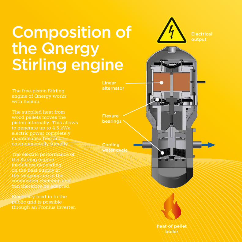
The free-piston Stirlingengine of Qnergy workswith helium.
The supplied heat from wood pellets moves the piston internally. This allows to generate up to 4.5 kWe electric power completely maintenance-free and environmentally friendly.
The electric performance ofthe Stirling engine modulates depending on the heat supply or the temperature in the combustion chamber, and can therefore be adapted.
Electricity feed-in to the public grid is possible through an Fronius inverter.
composition of the Qnergy Stirling engine
linear alternator
Flexure bearings
cooling water cycle
heat of pellet boiler
electrical output
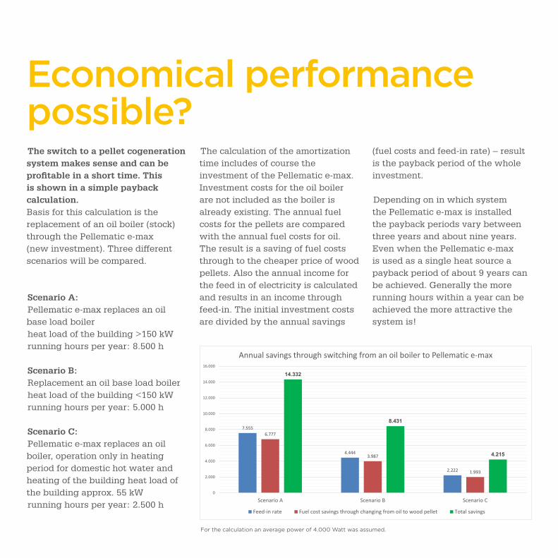
economical performance possible? The switch to a pellet cogeneration system makes sense and can be profitable in a short time. This is shown in a simple payback calculation. Basis for this calculation is the replacement of an oil boiler (stock) through the Pellematic e-max (new investment). Three different scenarios will be compared.
Scenario A: Pellematic e-max replaces an oil base load boilerheat load of the building >150 kWrunning hours per year: 8.500 h
Scenario B: Replacement an oil base load boilerheat load of the building <150 kWrunning hours per year: 5.000 h
Scenario C: Pellematic e-max replaces an oil boiler, operation only in heating period for domestic hot water and heating of the building heat load of the building approx. 55 kWrunning hours per year: 2.500 h
The calculation of the amortization time includes of course the investment of the Pellematic e-max. Investment costs for the oil boiler are not included as the boiler is already existing. The annual fuel costs for the pellets are compared with the annual fuel costs for oil. The result is a saving of fuel costs through to the cheaper price of wood pellets. Also the annual income for the feed in of electricity is calculated and results in an income through feed-in. The initial investment costs are divided by the annual savings
(fuel costs and feed-in rate) – result is the payback period of the whole investment.
Depending on in which system the Pellematic e-max is installed the payback periods vary between three years and about nine years. Even when the Pellematic e-max is used as a single heat source a payback period of about 9 years can be achieved. Generally the more running hours within a year can be achieved the more attractive the system is!
7.555
4.444
2.222
6.777
3.987
1.993
14.332
8.431
4.215
0
2.000
4.000
6.000
8.000
10.000
12.000
14.000
16.000
Scenario A Scenario B Scenario C
Annual savings through switching from an oil boiler to Pellematic e-max
Feed-in rate Fuel cost savings through changing from oil to wood pellet Total savings
For the calculation an average power of 4.000 Watt was assumed.

technical data
Pellematic e-max
Nominal power kW 55
Electrical power W 4.500 *
Width - total mm 1.286
Height - total mm 1.995
Height of suction system filling unit mm 1.635
Depth - total mm 1.230
Maximum unit dimension mm 890
Tilted height mm 2.160
Water supply/return Ø Zoll 6/4"
Height of inlet/return mm VL 1.343 / RL 686
Flue gas tube connection height mm 280
Dry weight fully equipped not packed kg ca. 780
Boiler efficiency rated power % ca. 93
Water capacity l ca. 152
Flue gas temperature rated power °C ca. 100
Flue gas tube diameter (at the boiler) mm 180
Chimney diameter min. 180 mm as per chimney calculation
Chimney construction qualified for condensing – solid fuel – dampresistant – N1 or P1 (as per flue calculation)
Electrical connection value 230 VAC, 50 Hz, 16 A
Volume hopper kg 66
Please pay attention to technical changes!* In operation it can be expected by temporally slightly delayed starting times, starts and stops with an average output of 4,000 watts.
a
a
a
a
a
a
aMin. distance from boiler side to the wall or building component
650 mm
b Min. ceiling height 2.300 mm