Peer Review – Dam Safety Action Classification (DSAC)...
71
Transcript of Peer Review – Dam Safety Action Classification (DSAC)...
Peer Review – Dam Safety Action Classification (DSAC) Group1
Wolf Creek Dam Consensus Report April 11, 2007
The Wolf Creek (DSAC) Peer Review Team has completed its review in accordance with Contract requirements. All comments, responses, issues and concerns resulting from this Peer Review have been fully addressed.
P.E., D.WRE, PhD
Jeff Bradley, P.E., D.WRE, PhD
Keith Ferguson, P.E., Vice Chair
Lll James Talbot, P.E.
Donald Bruce, C.Eng., PhD
Steve Poulos, P.E., PhD, Chair
John Vrymoed
John Vrymoed, P.E.
Wolf Creek Dam Consensus Report Engineering Risk and Reliability Analysis Peer Review – Dam Safety Action Classification Group 1 April 11, 2007
i
Table of Contents
Executive Summary............................................................................................... iii 1.0 Introduction .................................................................................................. 1
1.1 Project Description............................................................................................1 1.2 References and Sources of Factual Data...........................................................2
2.0 Site Visit (December 2006) .......................................................................... 3 2.1 General..............................................................................................................3 2.5 Surface Erosion Features ..................................................................................4 2.6 Cable Tunnel Settlement...................................................................................5 2.7 Drawdown Capacity..........................................................................................5 2.8 Rock Core Examination....................................................................................6 2.9 Wet Areas..........................................................................................................6 2.10 Concrete Dam Gallery Inspection....................................................................6
3.0 History of Seepage Issues........................................................................... 8 4.0 Graphic Depiction of Continuum of Failure Timeline.............................. 10 5.0 Safety in Context of Failure Continuum ................................................... 11 6.0 Dissenting Views........................................................................................ 12 7.0 SPRA and Proposed Risk Reduction/Mitigation Measures .................... 13
7.1 Failure Modes .................................................................................................13 7.2 Failure Modes of Primary Concern.................................................................13 7.3 Proposed Risk Reduction Measures................................................................13
7.3.1 Immediate Risk Reduction Measures ................................................ 14 7.3.2 Short-term Risk Reduction Measures ................................................ 14 7.3.3 Long-term Risk Reduction Measures ................................................ 15
7.4 Risk-based Reservoir Pool/Operation Restrictions.........................................17 7.4.1 Are the proposed risk-based reservoir pool/operation restrictions
appropriate?........................................................................................ 17 7.4.2 Are there considerations related to the reservoir pool/operation
restrictions that the Panel member would like to comment on further?............................................................................................... 18
7.5 Time for Response ..........................................................................................18 7.5.1 Service Life Without Intervening Actions......................................... 18 7.5.2 Recommended Timeframe to Implement Actions............................. 18
7.6 Distress Indicators/Triggering Events.............................................................19 7.7 Questions Asked of the Panel .........................................................................20
7.7.1 Is the proposed remediation with a cutoff wall appropriate?............. 20 7.7.2 Residual risk in final product due to existing embankment and
foundation damage? ........................................................................... 20 7.7.3 Reliability of cutoff wall? Corps does not have a set position on this
like the USBR 1x10⁻⁴. ........................................................................ 21
Wolf Creek Dam Consensus Report Engineering Risk and Reliability Analysis Peer Review – Dam Safety Action Classification Group 1 April 11, 2007
ii
7.7.4 Is an embankment dam ever appropriate in this environment? ........ 21 7.7.5 Feasibility of replacing/reinforcing embankment with an RCC
dam?................................................................................................... 22 7.7.6 Are risk-based costs an appropriate means of assessing the best
remediation option? ........................................................................... 22 8.0 Conclusions and Recommendations ....................................................... 23 Figures Figure 1: Seepage Failure Mode Continuum Figure 2: Estimated Condition of Dam with Uncertainty Limits Figure 3: Timeline of Failure Stages Attachments Attachment A. References Attachment B. Summary of Data Source Opinions on Key Distress Indicators Attachment C. Site Visit Photos Referenced in Consensus Report Attachment D. Alternative Description of Events Leading to the Development of the
Critical Embankment Foundation Seepage and Piping Failure Mode
Wolf Creek Dam Consensus Report Engineering Risk and Reliability Analysis Peer Review – Dam Safety Action Classification Group 1 April 11, 2007
iii
Executive Summary
The DSAC (Dam Safety Action Classification) Peer Review Panel, (Panel) has found that the U.S. Army Corps of Engineers (Corps) Class 1 designation (Urgent and Compelling) of Wolf Creek Dam under the draft ETL 1110-2-XXXX “INTERIM RISK REDUCTION MEASURES FOR DAM SAFETY” is appropriate. There is compelling evidence that a piping failure mode has re-initiated, and is in an advanced “continuation” stage of development. At this stage of failure mode development, the Panel believes there is significant potential for failure of Wolf Creek Dam under the normal operating conditions. The time at which such a failure would occur is very difficult to predict. Therefore, it is essential to 1) take immediate short-term actions to avoid failure and to reduce risks to the public, and 2) to expedite investigations, design and construction of long-term repairs. The conclusions and recommendations of the Panel are as follows:
1. Lower Reservoir Level: The reservoir water levels should immediately be lowered and maintained at a lower level until short-term corrective actions arrest further development of the failure mode and long-term corrective actions have been completed. The Panel believes that a target drawdown level of between 640 and 650 is needed to help avoid the development of a failure due to seepage through the embankment dam and its foundation. The Panel further recognizes that the selection of a target drawdown level must consider a number of factors, the most important of which is to prevent loss of life.
2. Conduct Foundation Grouting Immediately: The planned foundation grouting program is a critical short-term risk reduction program that must be completed as soon as possible under Monolith 37, under the embankment in the area immediately adjacent to Monolith 37, and in the area to the right of the point where the existing diaphragm wall was terminated.
3. Improve Existing Instrumentation: The entire investigation, piezometer and settlement instrumentation system and monitoring program for the dam, including the planned investigations and instrumentation to be installed as part of the grouting program should be independently reviewed as soon as possible. The system for measuring ongoing deformations of the dam crest and key areas along the downstream slope and the wrap-around section of the embankment is not considered adequate and needs to be substantially modified as soon as possible so that reliable deformation measurements can be obtained. Additional investigations and instrumentation are recommended in two “depression:” areas identified by the Panel including 1) a portion of the downstream wrap around section near the contact with the concrete dam, and 2) along the downstream slope near the end of the diaphragm wall to investigate the root cause of the depressions that have developed.
4. Review Reservoir Restriction: Once completed, the results of the supplemental investigation and grouting program, along with the supplemental instrumentation monitoring, should be independently reviewed to determine whether adjustments to the target reservoir drawdown level are appropriate.
Wolf Creek Dam Consensus Report Engineering Risk and Reliability Analysis Peer Review – Dam Safety Action Classification Group 1 April 11, 2007
1
1.0 Introduction
1.1 Project Description
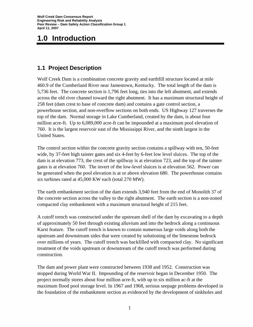
Wolf Creek Dam is a combination concrete gravity and earthfill structure located at mile 460.9 of the Cumberland River near Jamestown, Kentucky. The total length of the dam is 5,736 feet. The concrete section is 1,796 feet long, ties into the left abutment, and extends across the old river channel toward the right abutment. It has a maximum structural height of 258 feet (dam crest to base of concrete dam) and contains a gate control section, a powerhouse section, and non-overflow sections on both ends. US Highway 127 traverses the top of the dam. Normal storage in Lake Cumberland, created by the dam, is about four million acre-ft. Up to 6,089,000 acre-ft can be impounded at a maximum pool elevation of 760. It is the largest reservoir east of the Mississippi River, and the ninth largest in the United States. The control section within the concrete gravity section contains a spillway with ten, 50-feet wide, by 37-feet high tainter gates and six 4-feet by 6-feet low level sluices. The top of the dam is at elevation 773, the crest of the spillway is at elevation 723, and the top of the tainter gates is at elevation 760. The invert of the low-level sluices is at elevation 562. Power can be generated when the pool elevation is at or above elevation 680. The powerhouse contains six turbines rated at 45,000 KW each (total 270 MW). The earth embankment section of the dam extends 3,940 feet from the end of Monolith 37 of the concrete section across the valley to the right abutment. The earth section is a non-zoned compacted clay embankment with a maximum structural height of 215 feet. A cutoff trench was constructed under the upstream shell of the dam by excavating to a depth of approximately 50 feet through existing alluvium and into the bedrock along a continuous Karst feature. The cutoff trench is known to contain numerous large voids along both the upstream and downstream sides that were created by solutioning of the limestone bedrock over millions of years. The cutoff trench was backfilled with compacted clay. No significant treatment of the voids upstream or downstream of the cutoff trench was performed during construction. The dam and power plant were constructed between 1938 and 1952. Construction was stopped during World War II. Impounding of the reservoir began in December 1950. The project normally stores about four million acre-ft, with up to six million ac-ft at the maximum flood pool storage level. In 1967 and 1968, serious seepage problems developed in the foundation of the embankment section as evidenced by the development of sinkholes and

Wolf Creek Dam Consensus Report Engineering Risk and Reliability Analysis Peer Review – Dam Safety Action Classification Group 1 April 11, 2007
2
muddy flows in the tailrace. An emergency investigation and grouting program was completed shortly thereafter. The emergency grouting was not viewed as a long-term solution and a more permanent solution was sought. After convening a board of consultants in 1972 studying numerous alternatives, and then preparing a final design, the District completed construction of a concrete diaphragm wall between 1975 and 1979. During construction, due to cost concerns, the length and depth of the wall were reduced from the original design intent. Additional details of the seepage problems that developed and the remediation program that was completed are provided in Section 3.0. 1.2 References and Sources of Factual Data
The Panel has reviewed summaries and technical interpretations contained in a variety of sources of information prepared by Corps personnel, their consultants, and appointed “Panels of Experts”. These sources of information are listed in Attachment A. The present Panel has relied on the accuracy of these summaries and technical interpretations and in particular the analysis of the distress indicators that have been identified, in formulating the opinions presented in this report. The Panel acknowledges that certain observations and information relating to the distress indicators is open to different interpretations, reflecting the accuracy and veracity of the data. Therefore, the Panel has carefully considered the verbal and written opinions of all investigators who have been part of the ongoing investigations or who have previously reviewed and evaluated the condition of the dam. The Panel has prepared a summary of these opinions relative to key distress indicators, (presented in Attachment B) to support the historical basis of its opinions, conclusions and recommendations.
Wolf Creek Dam Consensus Report Engineering Risk and Reliability Analysis Peer Review – Dam Safety Action Classification Group 1 April 11, 2007
3
2.0 Site Visit (December 2006)
2.1 General
Five members of the Panel (all except Dr. Poulos) visited the site with Mr. Jody Stanton of the District on December 11, and 12, 2006, to help develop opinions and recommendations, and preparation of this consensus report. A summary of the key findings related to our site visit is provided below. Illustrative photographs taken during the site visit and referenced in the text that follows are presented in Attachment C. Conclusions and recommendations that are based in part on the site visit are included in Section 8 – Conclusions and Recommendations.
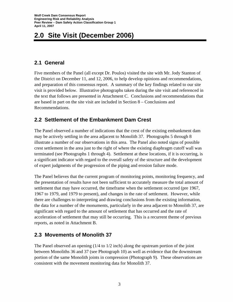
2.2 Settlement of the Embankment Dam Crest The Panel observed a number of indications that the crest of the existing embankment dam may be actively settling in the area adjacent to Monolith 37. Photographs 5 through 8 illustrate a number of our observations in this area. The Panel also noted signs of possible crest settlement in the area just to the right of where the existing diaphragm cutoff wall was terminated (see Photographs 1 through 4). Settlement at these locations, if it is occurring, is a significant indicator with regard to the overall safety of the structure and the development of expert judgments of the progression of the piping and erosion failure mode. The Panel believes that the current program of monitoring points, monitoring frequency, and the presentation of results have not been sufficient to accurately measure the total amount of settlement that may have occurred, the timeframe when the settlement occurred (pre 1967, 1967 to 1979, and 1979 to present), and changes in the rate of settlement. However, while there are challenges to interpreting and drawing conclusions from the existing information, the data for a number of the monuments, particularly in the area adjacent to Monolith 37, are significant with regard to the amount of settlement that has occurred and the rate of acceleration of settlement that may still be occurring. This is a recurrent theme of previous reports, as noted in Attachment B. 2.3 Movements of Monolith 37 The Panel observed an opening (1/4 to 1/2 inch) along the upstream portion of the joint between Monoliths 36 and 37 (see Photograph 10) as well as evidence that the downstream portion of the same Monolith joints in compression (Photograph 9). These observations are consistent with the movement monitoring data for Monolith 37.
Wolf Creek Dam Consensus Report Engineering Risk and Reliability Analysis Peer Review – Dam Safety Action Classification Group 1 April 11, 2007
4
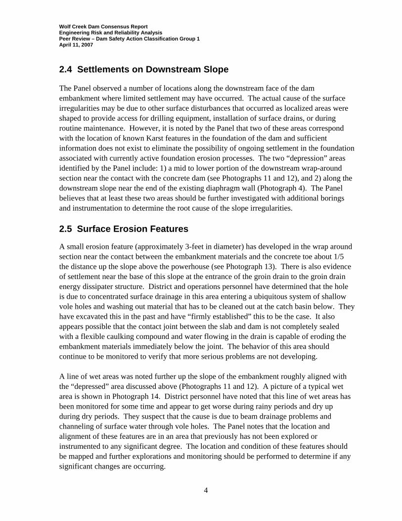
2.4 Settlements on Downstream Slope The Panel observed a number of locations along the downstream face of the dam embankment where limited settlement may have occurred. The actual cause of the surface irregularities may be due to other surface disturbances that occurred as localized areas were shaped to provide access for drilling equipment, installation of surface drains, or during routine maintenance. However, it is noted by the Panel that two of these areas correspond with the location of known Karst features in the foundation of the dam and sufficient information does not exist to eliminate the possibility of ongoing settlement in the foundation associated with currently active foundation erosion processes. The two “depression” areas identified by the Panel include: 1) a mid to lower portion of the downstream wrap-around section near the contact with the concrete dam (see Photographs 11 and 12), and 2) along the downstream slope near the end of the existing diaphragm wall (Photograph 4). The Panel believes that at least these two areas should be further investigated with additional borings and instrumentation to determine the root cause of the slope irregularities. 2.5 Surface Erosion Features
A small erosion feature (approximately 3-feet in diameter) has developed in the wrap around section near the contact between the embankment materials and the concrete toe about 1/5 the distance up the slope above the powerhouse (see Photograph 13). There is also evidence of settlement near the base of this slope at the entrance of the groin drain to the groin drain energy dissipater structure. District and operations personnel have determined that the hole is due to concentrated surface drainage in this area entering a ubiquitous system of shallow vole holes and washing out material that has to be cleaned out at the catch basin below. They have excavated this in the past and have “firmly established” this to be the case. It also appears possible that the contact joint between the slab and dam is not completely sealed with a flexible caulking compound and water flowing in the drain is capable of eroding the embankment materials immediately below the joint. The behavior of this area should continue to be monitored to verify that more serious problems are not developing. A line of wet areas was noted further up the slope of the embankment roughly aligned with the “depressed” area discussed above (Photographs 11 and 12). A picture of a typical wet area is shown in Photograph 14. District personnel have noted that this line of wet areas has been monitored for some time and appear to get worse during rainy periods and dry up during dry periods. They suspect that the cause is due to beam drainage problems and channeling of surface water through vole holes. The Panel notes that the location and alignment of these features are in an area that previously has not been explored or instrumented to any significant degree. The location and condition of these features should be mapped and further explorations and monitoring should be performed to determine if any significant changes are occurring.
Wolf Creek Dam Consensus Report Engineering Risk and Reliability Analysis Peer Review – Dam Safety Action Classification Group 1 April 11, 2007
5
2.6 Cable Tunnel Settlement
The Panel observed conditions along the exterior and interior of the cable tunnel. The Panel’s observations suggest that the cable tunnel may have settled in an area approximately aligned with a notable Karst feature and previous sinkhole development. The settlement has lead to compression of a joint and extrusion of joint filler material that appeared to be at a location of maximum settlement and tension cracking of the tunnel at the extreme (outer) limits of the settlement where the cable tunnel would be subject to bending and the development of tensile stresses. In the year 2000, the District sealed the leaky joints and installed crack survey pins across some of the cracks and survey monuments along the floor of the cable tunnel. Monitoring of these items has indicated no significant movements in the tunnel since they were installed. The Panel has not evaluated the settlement monitoring data that have been gathered by the District. However, based on our observations, we concur with the District’s opinion that the settlement could be the results of 1) erosion and piping of foundation material, or 2) long-term consolidation. The cracking that would result from either of these mechanisms could be influenced by the location of a bedrock knob and the change from a rock to soil bearing profile along the base of the conduit. The Panel also believes that the settlement attributable to foundation erosion could be the result of two different erosion mechanisms including 1) piping and erosion of soils adjacent and immediately under the conduit through cracks or the foundation drain system, or 2) a deeper, previously active erosion process along the Karst feature where sinkholes developed. The latter of these two mechanisms would indicate continuation and/or progression of foundation erosion threatening the integrity of the dam and a very serious dam safety concern. The Panel recommends that monitoring of the cable tunnel should continue on a regular basis. Should any additional settlement or distress occur, the settlement should be evaluated and the root cause determined. The ability of the existing instrumentation monitoring program to determine the root cause associated with these potential mechanisms should be independently reviewed. If appropriate, the instrumentation system and monitoring program (including the frequency of readings) should be modified. 2.7 Drawdown Capacity
Information presented by operations personnel at the site suggest that the existing power generation facilities and sluiceways may have the ability to draw down the reservoir at a significantly higher rate (0.5 to 1 foot per day at a maximum reservoir water surface elevation of 723) than was previously represented to the Panel.
Wolf Creek Dam Consensus Report Engineering Risk and Reliability Analysis Peer Review – Dam Safety Action Classification Group 1 April 11, 2007
6
2.8 Rock Core Examination
Rock cores were examined from one boring drilled in the right abutment and another boring drilled in the area immediately east of Monolith 37 of the concrete section of the dam. The rock cores were generally very competent with little sign of solutioning and infilling materials. The borings were located by District staff in areas between Karst features for the purpose of determining the unconfined compressive strength of the rock to help determine if hydromills were feasible and to provide these data to contractors (i.e. for future cut-off wall construction). The Panel anticipates that rock cores from boring from an area where a Karst feature was encountered would show substantially different characteristics. 2.9 Wet Areas
Not all of the wet areas and locations of historical seepage were observed. The Panel understands that the wet areas develop during higher reservoir storage levels. The wet areas and locations of historical seepage that were observed had dried up considerably from what is typically noted when normal operating reservoir levels are around elevation 723 in the early summer. The reservoir level at the time of this site visit was about elevation 693 (approximately 30 feet lower than the maximum normal pool during summer but within the normal winter drawdown range). It was reported that generally the wet areas do not have flowing water, but show wetness and some ponding. Areas of seepage along the riverbank downstream from the power switchyard have flowing water during low river levels, but are submerged during high river levels that may occur daily because of the power generation schedule. It is not known how much of the seepage on the riverbank is from recharge during high river levels, or leakage from the fish hatchery, as opposed to seepage through Karst features of the foundation. Generally, observable seepage rates were very low in the areas that were seen during the site visit. It is not known how much seepage may discharge further downstream in the river from the continuation of Karst features in the foundation. 2.10 Concrete Dam Gallery Inspection
Panel members inspected the galleries in the concrete section of the dam. Very little movement has occurred on the joints between Monoliths of the dam and very little leakage is occurring at most of the joints. The exception is at two joints near the powerhouse where copper waterstops apparently have broken loose to let substantial water leak through these two joints. Currently, the leakage from the broken waterstops is being pumped out of the gallery from a nearby sump without any detrimental effects to the dam. It was also noted that discharge from the foundation drains into the gallery is very minimal. The District has noted that the foundation drains in

Wolf Creek Dam Consensus Report Engineering Risk and Reliability Analysis Peer Review – Dam Safety Action Classification Group 1 April 11, 2007
7
the concrete section are monitored and maintained on a regular basis. Uplift pressures are being monitored by a series of uplift cells and these data, like the leakage from the foundation drains, have been consistent over many years. The drains were last cleaned in 2003.
Wolf Creek Dam Consensus Report Engineering Risk and Reliability Analysis Peer Review – Dam Safety Action Classification Group 1 April 11, 2007
8
3.0 History of Seepage Issues
Uncontrolled seepage through the rock foundation has threatened the stability of the 3940-foot long earth embankment. The original design and construction techniques used at Wolf Creek Dam followed the standard of practice for dams on Karst foundation in the 1930s and 1940s. However, several aspects of the foundation design have subsequently contributed to the development of serious seepage and piping problems as has been the case for a number of dams on Karst foundations that were designed during the same period. The dam’s limestone foundation is riddled throughout with an interconnected system of open Karstic (voids) features caused by millions of years of solutioning. These features range in size from fractions of an inch to more than 40 feet in width and height. At the time the dam was constructed, these Karst features were filled or partially filled with residual soil. Under the pressure of the reservoir head, which typically ranges between 175 and 200 feet, piping from high gradients or internal erosion has been initiated through these Karst features, removing the infilling material. In 1967 and 1968, the symptoms of internal erosion were observed under the downstream slope of the embankment. During this time, a sinkhole developed on the downstream right toe and two sinkholes developed on the random fill above the switchyard that extended from the embankment surface through 40 feet of alluvial and fill material to the top of rock. These sinkholes were preceded by wet areas and muddy flows in the tailrace. Additional wet areas and seepage were noted along the area downstream of the embankment. The total extent of damage that occurred in the dam and foundation prior to grouting and cutoff wall construction was not determined. Erosion and piping of the Karst infilling materials may have extended up to, and through the original core trench of the dam. Responding to the near dam failure in 1968, the Corps embarked on an emergency exploration and grouting program from 1968 to 1970. Most of the 290,000 cubic feet of grout solids were placed in the heavily solutioned rock in the area where the embankment wraps around the end of the concrete Monoliths (near the end of Monolith 37). Reportedly, “the grouting saved the dam”. However, a “permanent” cutoff was desired. A deep concrete wall was installed between 1975 and 1979 in two contiguous sections. Another wall was located downstream between the switchyard and the tailrace to protect the switchyard foundation from the surging and erosion during power generation. The main wall was built from the crest of the embankment where it connects to the end of the concrete section of the dam and extends approximately two-thirds of the distance toward the right abutment. There is evidence that the main concrete wall installed from the crest of the dam
Wolf Creek Dam Consensus Report Engineering Risk and Reliability Analysis Peer Review – Dam Safety Action Classification Group 1 April 11, 2007
9
did not cutoff solution features under the end of the concrete section of the dam, did not extend far enough toward the right abutment, and most likely did not extend deep enough into the bedrock to intercept all major Karstic features. The length and depth of the wall (maximum 280 feet) were determined at the time by technological and economic constraints. Following remediation, seepage and other indicators of potential piping problems have progressively worsened over the years. Initially, the piezometric levels downstream of the crest wall did not reduce as expected and some have gradually increased, indicating seepage pressures are increasing downstream of the wall. Downstream wet areas and seepage as evidenced by the number and size of wet areas have gradually returned to nearly the levels that existed before the emergency work was completed. Settlement of the crest of the embankment is arguably occurring near both ends of the existing main concrete wall, and is highest near the end of the concrete section at Monolith 37. Soft areas have been found in the lower reaches of the embankment during recent investigation drilling. Seepage on the river bank below the switchyard has increased causing some instability of the river bank. Major rehabilitation has been proposed to mitigate the worsening conditions that appear to be approaching those that existed before the previous emergency work was performed. It is noted that, due to different interpretations of these “indicators of failure”, there is not yet consensus between all parties involved (i.e. District, Headquarters and the Panel) as to the degree and extent of worsening seepage conditions since 1979, as noted in Section 1.2.
Wolf Creek Dam Consensus Report Engineering Risk and Reliability Analysis Peer Review – Dam Safety Action Classification Group 1 April 11, 2007
10
4.0 Graphic Depiction of Continuum of Failure Timeline
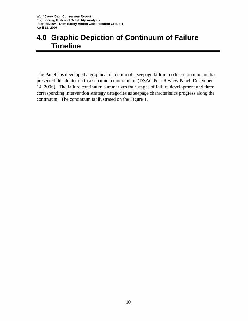
The Panel has developed a graphical depiction of a seepage failure mode continuum and has presented this depiction in a separate memorandum (DSAC Peer Review Panel, December 14, 2006). The failure continuum summarizes four stages of failure development and three corresponding intervention strategy categories as seepage characteristics progress along the continuum. The continuum is illustrated on the Figure 1.
Seepage Failure Development
FailureStage
Initi
atio
n
None Continuation Progression BreachFormation
InterventionStrategy
Routine O & MSafety Evaluations
Budgetary
Short-termEmergency
Heroic/CrisisLong-termBudgetary
Dam performs as expected. Routine safety inspections show no problems. Safety evaluations may suggestpotential for long-term seepage concern.
Seepage failure mode initiatesdue to loading event that causes development of concentrated leak or backward erosion. Initiation may occur in the embankment, in the foundation, or at the interface between the embankment and foundation.
Seepage failure mode is not arrested due to filter, cutoff, or other intervention activity. The piping or erosion continues toward the source of water at accelerating rate due to increasing gradients and flow quantity.
Piping/erosion widens and/or deepens as flows increase due to roof formation and no other restraint to growth. Amount of flow continues to increases causing piping/erosion feature to grow rapidly.
Seepage flow not arrested due to collapse and erosion continues until dam crest is breached due to sinkholes, crest settlement, instability of slopes, or unravelling of the downstream slope
Long-term intervention may include:
Filters/drainsPositive cutoffsGroutingFilter/drainage bermsRelief wells
Short-term interventionmay include:
Modified operationsReservoir drawdownReservoir restrictionsGroutingFilter/drains/bermsRelief wells
Heroic/Crisis intervention may include:
Emergency drawdownEvacuation of downstream residentsFiltersDownstream gradient reductionCrack or pipe filling
Class IClass II/III
EAP Implementation
IRRMP Implementation
Prepared by DSAC Peer Review Panel12-06
Figure 1: Seepage Failure Mode Continuum
Wolf Creek Dam Consensus Report Engineering Risk and Reliability Analysis Peer Review – Dam Safety Action Classification Group 1 April 11, 2007
11
5.0 Safety in Context of Failure Continuum
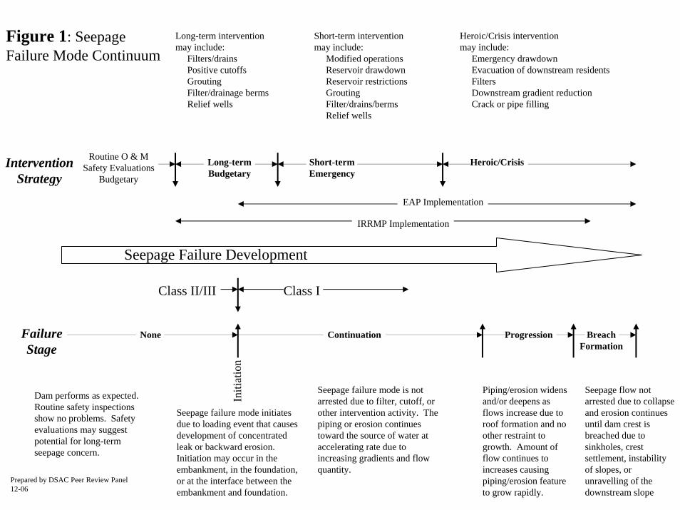
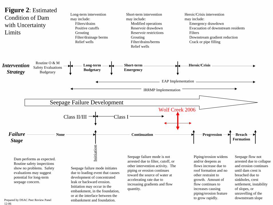
The Panel believes that the current condition of the Wolf Creek embankment is as shown in the failure mode continuum diagram provided on Figure 2. The information on Figure 2 indicates that a seepage related failure mode has re-initiated and is in an advanced continuation stage. The confidence interval of the Panel’s current assessment is also shown on Figure 2. Additional comments on the Panel’s assessment are contained in a separate memorandum that has been prepared and submitted to the Corps (December 14, 2006). To further clarify the timeline related to the development of a seepage/piping related failure, the Panel has also developed an illustrative histograph whereby the seepage failure stage at Wolf Creek Dam has been given a numerical score and plotted with time. This histograph is shown on Figure 3. A score of zero represents seepage failure initiation and the beginning of the continuation stage of failure development, while the scores of 100 and 140 represent the onset of the Progression and Breach failure stages, respectively. The changes in the failure stage points on the Histograph correspond to times of intervention (remediation) during the life of the project and the subsequent deterioration along the continuum that is occurring. The last data point represents completion of the recently initiated grouting program and construction of the planned new diaphragm wall. This data point is judged commensurate with a score of 20, after which the score is estimated to increase with time, at a rate that will be slower than the rate of deterioration that starts at the completion of the existing diaphragm wall in 1979.
Seepage Failure Development
FailureStage
Initi
atio
n
Progression BreachFormation
None Continuation
InterventionStrategy
Routine O & MSafety Evaluations
Budgetary
Short-termEmergency
Heroic/CrisisLong-termBudgetary
Dam performs as expected. Routine safety inspections show no problems. Safety evaluations may suggestpotential for long-term seepage concern.
Seepage failure mode initiatesdue to loading event that causes development of concentrated leak or backward erosion. Initiation may occur in the embankment, in the foundation, or at the interface between the embankment and foundation.
Seepage failure mode is not arrested due to filter, cutoff, or other intervention activity. The piping or erosion continues toward the source of water at accelerating rate due to increasing gradients and flow quantity.
Piping/erosion widens and/or deepens as flows increase due to roof formation and no other restraint to growth. Amount of flow continues to increases causing piping/erosion feature to grow rapidly.
Seepage flow not arrested due to collapse and erosion continues until dam crest is breached due to sinkholes, crest settlement, instability of slopes, or unravelling of the downstream slope
Long-term intervention may include:
Filters/drainsPositive cutoffsGroutingFilter/drainage bermsRelief wells
Short-term interventionmay include:
Modified operationsReservoir drawdownReservoir restrictionsGroutingFilter/drains/bermsRelief wells
Heroic/Crisis intervention may include:
Emergency drawdownEvacuation of downstream residentsFiltersDownstream gradient reductionCrack or pipe filling
Class IClass II/III
EAP Implementation
IRRMP Implementation
Prepared by DSAC Peer Review Panel12-06
Wolf Creek 2006
Figure 2: Estimated Condition of Dam with Uncertainty Limits
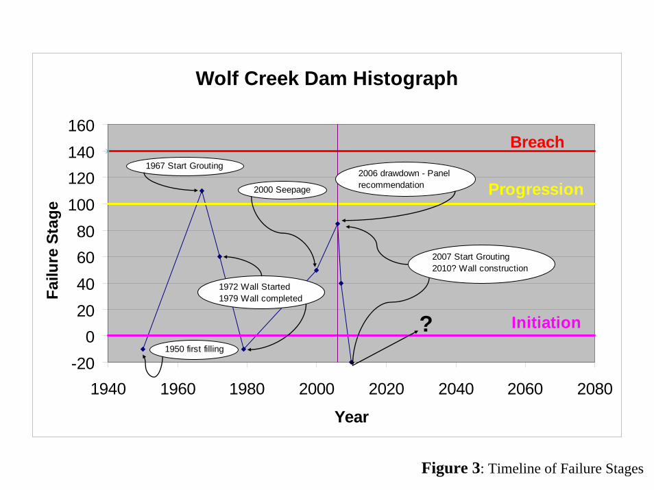
Wolf Creek Dam Histograph
Initiation
Progression
Breach
-200
20406080
100120140160
1940 1960 1980 2000 2020 2040 2060 2080
Year
Failu
re S
tage
?1950 first filling
1967 Start Grouting
1972 Wall Started1979 Wall completed
2000 Seepage
2006 drawdown - Panel recommendation
2007 Start Grouting2010? Wall construction
Figure 3: Timeline of Failure Stages
Wolf Creek Dam Consensus Report Engineering Risk and Reliability Analysis Peer Review – Dam Safety Action Classification Group 1 April 11, 2007
12
6.0 Dissenting Views
Members of the Panel have been contractually provided a framework to express a dissenting view or views in the form of a “Non-concurrence” report. This report represents a “consensus opinion” of the entire Panel. There are no dissenting views by any member of the Panel. Variations in Panel member opinions are represented by the confidence band presented on Figure 2.
Wolf Creek Dam Consensus Report Engineering Risk and Reliability Analysis Peer Review – Dam Safety Action Classification Group 1 April 11, 2007
13
7.0 SPRA and Proposed Risk Reduction/Mitigation Measures
7.1 Failure Modes
In support of the SPRA (Screening for Portfolio Risk Analysis) completed by the Corps, the Panel finds that all potential failure modes have been identified.
7.2 Failure Modes of Primary Concern
The Panel believes that the following potential failure modes are of primary concern:
• Embankment – Foundation Seepage and Piping
• Embankment – Stability
• Concrete Gravity Section – Foundation Seepage and Piping
• Embankment – Embankment Seepage and Piping With regard to the first failure mode above (Embankment – Foundation Seepage and Piping), while there are a number of locations along the embankment where this failure mode may be developing, the locations of primary concern are 1) the embankment foundation immediately adjacent to Monolith 37, and 2) the embankment foundation just beyond the end of the existing main cutoff wall. The Panel judges the dam to be in a critically near failure condition related to this failure mode, requiring immediate corrective actions as discussed further below. The Panel believes the Corps has presented good descriptions (e.g. the Major Rehabilitation Report (2005) and Panel briefing presentation (October 6, 2006)) of the events that would lead to the development of the failure mode of primary concern listed above. An expanded description for the Corps’ consideration is provided in Attachment D to this report.
7.3 Proposed Risk Reduction Measures
The Panel has evaluated the proposed risk reduction measures by sorting them into three general categories; 1) immediate (heroic), 2) short-term, and 3) long-term.

Wolf Creek Dam Consensus Report Engineering Risk and Reliability Analysis Peer Review – Dam Safety Action Classification Group 1 April 11, 2007
14
7.3.1 Immediate Risk Reduction Measures
The Corps is assessing immediate (pool drawdown and operating restriction) measures to intervene with the further development of the failure mode of primary concern. The Panel believes that it is critical that the Corps evaluate alternative means to lower the reservoir and to maintain the lowered level throughout the year. Following the initial briefing of the Panel, we recommended a drawdown to an elevation between 610 and 650 based on a simplified estimate of what may be necessary to arrest the foundation erosion process. Since then, the Panel has reviewed and evaluated additional information and performed a site visit. As a result, we have revised our recommended drawdown level to elevation 640 to 650. The Panel recognizes that there are many important considerations related to establishing a target reservoir restriction level including 1) potential impacts of dam failure at the drawdown level, and 2) the loss of flood control, hydropower, water supply, and recreation benefits. The Panel recommends that flood routings for a range of possible failure breaches with and without an upstream flood, should be conducted to further support the decision regarding the drawdown elevation. 7.3.2 Short-term Risk Reduction Measures
The Panel concurs with the proposed short-term risk reduction program of foundation grouting beginning in the area adjacent to and under Monolith 37. The Panel cannot over-emphasize the urgency of this action (combined with reservoir drawdown). Grouting should start immediately. The grouting should be done using the most up-to-date techniques to fill voids that have developed since the previous grouting work and cutoff seepage around the existing cutoff wall. Information should be collected during drilling operations for the grouting that will allow further evaluation of the foundation conditions and provide information for design of the new deep wall proposed for long-term risk reduction. The Intelligrout (or equivalent) system is recommended for collecting information and producing the appropriate grouting results similar to other recent Corps’ drilling and grouting projects, such as Patoka, Mississinewa and Clearwater, where the successful contractor was procured by a “Best Value” approach. Further, the proposed grouting program should be independently reviewed. We expect that an independent review would address the following:
• Grout hole orientation concepts and patterns (given the clay-filled vertical features in the rock).
• Need for "blow out" preventers in the gallery, while conducting drilling below reservoir levels.
• Definition of the rheological properties of the "stable grouts" appropriately specified.
• Definition of the computer-controlled system.
Wolf Creek Dam Consensus Report Engineering Risk and Reliability Analysis Peer Review – Dam Safety Action Classification Group 1 April 11, 2007
15
• Water pressure testing requirements (single and multipressure)
• Consideration of refusal criteria for the grouting of each stage.
• Definition of target residual permeabilities
The Panel has stated that, if the District elects to limit the target drawdown of the reservoir to a higher level because of other considerations, then the grouting program should be expanded as appropriate (including the limits of the grouting, spacing of grout holes etc.), accelerated and optimized, given our level of concern about the status of the structure on the continuum of failure. To maximize the ease of the grouting work, the reservoir should be drawn down as much as reasonably practicable during grouting operations. By starting the grouting operations immediately, and using appropriate technical resources for data gathering and evaluation, the Panel believes that District is taking appropriate steps with respect to both pushing ahead with this remedial work and potentially increasing its effectiveness. We believe that the "Panel of Experts" being convened by the District (separate from the DSAC Peer Review Panel) will find the quality of data produced by computer based systems to be especially valuable in their appraisal of progress as indeed has been experienced in the other projects listed above. The Panel further recommends that the system of instrumentation (piezometers and settlement monuments) and the approach to monitoring should be critically and independently reviewed and altered as appropriate as soon as possible. Appropriate additional investigations and instrument installation should be performed prior to grouting so that a baseline of data is established against which the effects of grouting can be assessed. 7.3.3 Long-term Risk Reduction Measures
7.3.3.1 Alternatives Analysis
The Panel has reviewed information provided by the Nashville District on the Alternatives Analysis performed for the Wolf Creek Project – (Major Rehabilitation Evaluation, Briefing Document, dated July 2004). The report states that all conceivable plans for treating the foundation problems beneath the Wolf Creek earth embankment have been considered. It summarizes nine alternative plans. Cost estimates were developed for six of the plans that were considered feasible. Based on these studies, it was concluded that a composite cutoff wall was the best alternative for long-term risk reduction. The Panel notes that the studies forming the basis of the Alternatives Analysis were conducted in 1972. The District has further indicated that these studies were updated for the 2005 Major Rehabilitation Report. The update was limited to escalating the costs to their current values for the replacement of the embankment option and that the costs for the other alternatives included MCACES level cost analyses.
Wolf Creek Dam Consensus Report Engineering Risk and Reliability Analysis Peer Review – Dam Safety Action Classification Group 1 April 11, 2007
16
The Panel recommends that a new Alternatives Analysis for the Wolf Creek Dam project be conducted. A new Alternative Analysis should, at a minimum, integrate the following:
• Consideration of long-term risk, over at least a 25 year period, by incorporating all or pertinent elements of the current risk assessment study
• Selection of the preferred alternative based on “best value,” also over a period of not less than 25 years, instead of present day least cost values
• Broaden the alternatives. At a minimum, consider 1) replacement of the existing embankment dam with an RCC Dam tied into the existing concrete structure, and 2) major rehabilitation of the existing embankment dam by removing and replacing the downstream portion of the embankment, alluvium, and weathered bedrock starting on the upstream slope of the existing embankment at approximately elevation 740. A number of the elements of this design would be similar to the rehabilitation concept that was developed and implemented by the Corps at Fern Ridge Dam in Oregon in 2004. For this alternative, provide a positive cutoff wall through the Leipers formation beginning at the prepared bedrock surface and grout the Cathey’s formations below the wall. Prepare and treat the exposed bedrock surface with particular emphasis on robust treatment of exposed Karst features with backfill concrete and placement of a concrete slab on the surface of the bedrock to isolate the embankment from the Karst. Replace the embankment incorporating a blanket and chimney drain in the cross-section
• Incorporate the Corps’ 3 R’s in the evaluation process and the selection of the preferred alternative
• Consideration of the Panel’s comments on the cutoff wall provided in Section 7.3.3.2 below
7.3.3.2 Composite Cutoff Wall Alternatives
The Panel generally believes that a composite cutoff wall (i.e. grouting plus concrete diaphragm) is a viable long-term risk reduction alternative. The following comments however, are offered for consideration in the Alternative Analysis for such a wall:
• The proposed wall is a single line-of-defense. The Panel recognizes the options for a second line-of-defense are very limited and potentially very expensive. If such a single line of defense system is adopted, it should be recognized that further treatment may be necessary in the future. As discussed further below, the Panel encourages the Corps to evaluate other alternatives for the existing embankment dam section that would provide a solution with multiple lines-of-defense for this particular site.
• Required depth of wall and related feasibility of construction is a major concern. The design objective for the depth of the wall and grouting below the wall must be fully addressed. There must be a high degree of confidence that the rock below the toe of
Wolf Creek Dam Consensus Report Engineering Risk and Reliability Analysis Peer Review – Dam Safety Action Classification Group 1 April 11, 2007
17
the wall has an acceptably low, uniform permeability either naturally or as a consequence of a well-conducted grouting program. The feasibility of wall construction techniques should be evaluated when the additional information from the grouting program is available.
• A full-scale test section should be conducted to confirm constructability and locally evaluate the performance of a new wall.
• Special attention must be paid during construction to the hydrogeological response of the entire dam/foundation system. The wall will be built with some sort of progressive “closure” system such as primary and secondary panels or piles. The early panels or piles may redirect and focus foundation flow in the Karst and trigger erosion in areas of concentrated flow that threaten the construction work or the safety of the dam.
• The integrity of the wall must be proved by appropriate verification methods following construction such as coring and testing of the wall. Localized remediation should be conducted as appropriate.
• Damage to the existing dam needs to be further evaluated. The condition and performance of the upstream and downstream shell portions of the embankment are vital to the long-term safety, reliability, and effectiveness of a cutoff wall system. The Corps should assess the condition of the upstream and downstream shells and verify that potential settlement or instability will not threaten the performance of a new cutoff wall system. Damaged portions of the embankment and embankment foundation may require remediation to provide the required support and long-term performance of the cutoff.
• A carefully designed and implemented instrumentation monitoring program will be required to confirm the safe long-term performance of the dam.
• A positive cutoff (W.F. George type) wall should be considered under the concrete dam section, again, depending on an evaluation of the drilling and grouting work currently contemplated in this area.
7.4 Risk-based Reservoir Pool/Operation Restrictions
7.4.1 Are the proposed risk-based reservoir pool/operation restrictions appropriate?
At the time of the initial Panel briefing in early October, 2006 the Panel understood that the Corps had not proposed any substantial reservoir pool/operation restrictions. Operations had been modified in 2005 to take out the peaks in the early spring period and to hold the lake elevation as closely as possible to the operation band of the hydropower curve. Subsequently, the Corps has decided to drawdown the reservoir to elevation 680. As noted in Section 7.3.1 above, the Panel believes that it may be necessary to draw the reservoir down to elevation 640 to 650 in order to adequately reduce the seepage forces acting in the
Wolf Creek Dam Consensus Report Engineering Risk and Reliability Analysis Peer Review – Dam Safety Action Classification Group 1 April 11, 2007
18
foundation of the dam, arrest the development of the seepage and piping failure modes, and to minimize further damage to the dam and dam foundation until long-term corrective actions are completed. 7.4.2 Are there considerations related to the reservoir pool/operation
restrictions that the Panel member would like to comment on further?
As noted in Section 7.3 above, the Panel recognizes that the decision on the level of drawdown and the corresponding structural modifications required to maintain that drawdown is complex and involves a number of technical, flood control, water supply and other stakeholder considerations. The time required to achieve any significant drawdown may be substantial depending on inflow conditions. If it has not already been done, the current EAP (Emergency Action Plan) should be reviewed and updated as appropriate. Table top exercises should be performed to make sure that local emergency action personnel are fully trained on the elements of the plan and its implementation should it become necessary. The public should be periodically informed of the status of the EAP and any changes that are occurring. In this regard, it is clear that the District is engaged in an effective relationship with local new media. 7.5 Time for Response
7.5.1 Service Life Without Intervening Actions
The Panel has concluded that the effective service life of the embankment dam under normal operating conditions (i.e. lake levels above elevation 680) has ended. Without intervention, the Panel estimates that there is a very high likelihood of breach formation and loss of reservoir through the embankment section and its foundation within the next 5 years. This is substantially less than the time that will be required to complete the planning, design, and construction of short- and long-term corrective actions if full pool operations continue. 7.5.2 Recommended Timeframe to Implement Actions
The Panel concurs with the proposed upgraded foundation grouting program and recommends that this program be implemented with utmost urgency. The timeframe required to complete the design and construction of the preferred alternative for the embankment section should be minimized to the greatest extent possible. The reason for this degree of care is that no one can predict when this dam might progress to failure. Furthermore, a careful monitoring program should be established to improve the ability to judge if the failure condition is worsening. In addition, the Panel believes there are important feasibility issues that will impact the long-term reliability of the proposed wall. As noted in Section 7.3.3.1, we believe that it would be
Wolf Creek Dam Consensus Report Engineering Risk and Reliability Analysis Peer Review – Dam Safety Action Classification Group 1 April 11, 2007
19
prudent to revisit the previous alternatives analysis that was performed for the project to determine whether or not a rehabilitation concept that provides additional lines-of-defense would be a “best value” investment. The Panel also believes there may be significant safety issues associated with the existing concrete gravity dam section and that a possible seepage and piping failure of its foundation is a significant short- and long-term risk to the structure. The deterioration of the gravity section foundation requires additional evaluations and alternatives to the proposed foundation grouting program should be considered by the Corps as noted in Section 7.3.3, above. 7.6 Distress Indicators/Triggering Events
The Panel believes there are five indicators that suggest that a piping/erosion failure mode has re-initiated, is well into the continuation phase and may be very close to entering the progression phase of the seepage/piping failure mode continuum as described in Section 5. These indicators are complementary and consistent in terms of the conclusions that may be logically drawn relative to the current stage of failure development. They include:
• Increasing seepage
• Settlement of the crest and downstream slope of the dam
• Soft areas found in multiple borings in and under the dam.
• Rising piezometer levels downstream of the cutoff wall previously installed
• Seepage instability of the river bank
The Panel believes that the Corps has identified a number of the most significant distress indicators/triggering events associated with the failure mode of primary concern. In addition, 1) longitudinal cracking or slide development in the upstream or downstream slopes of the dam, and 2) development of whirlpools in the reservoir should be considered significant indicator/triggering events. The Panel offers the following additional comments for the Corps’ consideration:
• If water that is aggressive to calcium carbonate exists in the reservoir, solutioning of
the bedrock upstream and under the original core trench as well as in the vicinity of the existing cutoff wall may be contributing to the development of foundation seepage and changes in instrumentation reading at certain locations. The Panel’s experience suggests that the potential for solutioning of the bedrock at this site is very low. However, while it is certainly a secondary consideration, the Panel recommends that the Corps further evaluate this issue and include it as appropriate in the instrumentation monitoring and remediation evaluation process.
• If possible, seepage monitoring should include some measures of seepage water quality including turbidity. Seepage monitoring should be done at least bi-monthly.
Wolf Creek Dam Consensus Report Engineering Risk and Reliability Analysis Peer Review – Dam Safety Action Classification Group 1 April 11, 2007
20
During each time of measurement, the water flow rate and turbidity must be measured on an hourly basis for approximately 48 hours in succession in order to observe any intermittent piping that may be occurring.
• It is likely that the identified indicators/triggers will continue to be observed and to a greater degree until short- and long-term risk reduction measures are implemented. The Corps should determine what changes in the indicators would warrant implementation of the next warning/action levels of the EAP. This would include changes in key instrumentation readings.
• In addition, the Corps should develop a list of the most significant distress indicators/triggering events associated with the concrete section, particularly in the areas of Monolith 37 and other locations where there are known and suspected foundation Karst defects.
7.7 Questions Asked of the Panel
7.7.1 Is the proposed remediation with a cutoff wall appropriate?
An updated Alternatives Analysis will determine if a cutoff wall is the appropriate remediation alternative. Absent this analysis, the Panel believes that the proposed cutoff installation will be essential. However, there is significant design, dam safety, constructability, and schedule issues and concerns related to the proposed composite cutoff wall system as discussed in Section 7.3.3 above, that remain to be resolved. The Panel further notes that the short-term grouting program proposed by the Corps will provide an excellent opportunity to gather additional information related to the existing wall performance and condition, as well as general foundation deterioration that has occurred. The Panel encourages the Corps to take maximum advantage of this opportunity and to make the grouting program information available at the earliest possible time for peer review. 7.7.2 Residual risk in final product due to existing embankment and
foundation damage?
The Panel believes that the depth design objective for the proposed composite cutoff wall system has not been fully established. Further, current technology for constructing deep walls in rock may not allow for deep enough construction to eliminate the risks associated with Karst in the Leipers and Cathy’s formations. If the cutoff is not constructed deep enough, a relatively short term improvement in the reliability of the dam will be achieved, and it will only be a matter of time before seepage problems re-develop. This is exactly what happened in the 1975-1979 remediation phase. At this time, a total depth of around 300 feet is judged to be the practical maximum for the type of wall that can be built in these conditions (assuming that the rock is too hard for hydromill excavation to greater depths).
Wolf Creek Dam Consensus Report Engineering Risk and Reliability Analysis Peer Review – Dam Safety Action Classification Group 1 April 11, 2007
21
The Panel also notes that a reduction in the pressures in the existing dam and foundation downstream of the short-term grouting or long-term cutoff wall construction could accelerate the collapse of any existing open Karst features leading to further damage to the dam and the development of slope stability issues. As noted above (Section 7.3.3), it is critical to assess the damage that has occurred to the embankment and foundation both upstream and downstream of a proposed cutoff wall system and determine the need for embankment and foundation remediation to improve the long-term reliability of the dam. 7.7.3 Reliability of cutoff wall? Corps does not have a set position on this like
the USBR 1x10⁻⁴.
The Corps has not established a position on the required reliability of dams, such as the USBR position of a 1 x 10⁻⁴ annualized probability of failure. The Panel does not have sufficient information to develop an estimate of the annualized probability of failure (reliability) for the proposed risk reduction alternative. The Panel does, however, offer the following comments with regard to reliability:
• In general, the reliability will be improved by installing the composite cutoff wall to greater depths than proposed.
• It may only be possible to achieve the desired reliability by replacing the existing embankment section with one of the two alternatives mentioned in Section 7.3.3.1 or other alternatives which incorporate foundation excavation, preparation, and construction of a positive cutoff wall. The elevation to which such a cutoff wall can be constructed would be lower for the two alternatives mentioned in Section 7.3.3.1 than can be achieved through the existing embankment and thereby provide for the desired reliability
7.7.4 Is an embankment dam ever appropriate in this environment?
The Panel generally believes that the design of this embankment dam and others of similar design is not appropriate for the foundation conditions that exist at this site. Those conditions include:
• A well-developed Karstic foundation material extending to depths that were not fully penetrated by a positive cutoff wall
• The presence of overburden under the upstream and downstream slopes of the embankment
• Failure to effectively treat Karst features under the central, and upstream and downstream zones of the dam in order to protect overburden and embankment materials from collapse or erosion processes in these features
Wolf Creek Dam Consensus Report Engineering Risk and Reliability Analysis Peer Review – Dam Safety Action Classification Group 1 April 11, 2007
22
If extensive treatments are employed to prevent the erosion of embankment materials and the formation of sinkholes in the embankment dam, it may be possible to improve the reliability of an embankment dam on a Karstic foundation. These treatments may involve concrete filling of voids under the embankment and a substantial layer of dental concrete to protect the embankment from erosion at the foundation contact. A durable cut off through the underlying Karst features is essential. 7.7.5 Feasibility of replacing/reinforcing embankment with an RCC dam?
The Panel recommends that the Corps evaluate an alternative RCC (roller compacted concrete) dam at this site for comparison to the proposed risk reduction alternative of the composite cutoff wall in the Alternatives Analysis. While there are very significant considerations related to the excavation and preparation of a suitable foundation for an RCC alternative, it would offer a significant increase in reliability and safety. Additional comments with regard to an RCC replacement dam alternative include:
• Foundation excavation objective will be a significant consideration and will likely require a positive cutoff of the Leipers formation. Significant over-excavation and treatment of existing Karst and damaged foundation areas should be anticipated.
• Significant reservoir drawdown will be required with corresponding loss of reservoir benefits. In addition, a large cofferdam may be required to complete the transition from the existing concrete section to the new RCC section, depending on the extent of the drawdown.
7.7.6 Are risk-based costs an appropriate means of assessing the best
remediation option?
Incorporation of risk-based costs in an Alternatives Analysis is appropriate and desirable for assessing the best remediation option. Present day costs and short term impacts should be a secondary consideration to providing public health and safety and restoring the long-term function of this valuable resource. It is a safe assumption that the value of benefits this project provides such as flood protection, recreation, and power generation will increase in time. The Panel notes that consideration of risk-based costs in the decision making process can be very informative. Our experience suggests that such considerations may reinforce the desirability of a more costly solution that provides significantly higher long-term reliability in this challenging geologic environment. Our experience further indicates that it is critical to remain objective in the evaluation of alternatives and to avoid the introduction of any bias due to external and/or special interest pressures.
Wolf Creek Dam Consensus Report Engineering Risk and Reliability Analysis Peer Review – Dam Safety Action Classification Group 1 April 11, 2007
23
8.0 Conclusions and Recommendations
The Panel has found that the Corp’s Class 1 designation (Urgent and Compelling) of Wolf Creek Dam under the draft ETL 1110-2-XXXX “INTERIM RISK REDUCTION MEASURES FOR DAM SAFETY” is appropriate. There is compelling evidence that a piping failure mode has re-initiated, and is in an advanced “continuation” stage of development. The Panel believes there is significant potential for failure of Wolf Creek Dam under normal operating conditions. The time at which such a failure would occur is very difficult to predict. Therefore, it is essential to 1) take immediate short-term actions to avoid failure and to reduce risks to the public, and 2) to expedite funding, investigations, design and construction of long-term repairs. Other conclusions and recommendations of the Panel are as follows:
• Lower Reservoir Level: The reservoir water levels should immediately be lowered and maintained at a lower level until short-term corrective actions arrest further development of the failure mode and long-term corrective actions have been completed. Based on information that has been provided to the Panel including instrument readings and estimates of seepage gradients in critical locations, the potential erodibility of Karst infilling and previous grout materials, and the characteristics of the diaphragm wall, we believe that a target drawdown level of between 640 and 650 is needed to help avoid the development of a failure due to seepage through the embankment dam and its foundation. This is the failure mode that is most critical for this dam. The Panel further recognizes that the selection of a target drawdown level must consider a number of factors, the most important of which is loss of life. The loss of benefits to upstream users of the water in the reservoir, loss of generating ability, and the loss of property values both upstream and downstream also should be considered.
• Start Foundation Grouting Immediately: The planned foundation grouting program is a critical short-term risk reduction program that must be completed as soon as possible. If the Corps determines that a target drawdown level of 640 to 650 is not practical, and that a higher target storage level of about 680 is appropriate, the Panel recommends that the foundation grouting program be completed by May 30, 2007 under Monolith 37, under the embankment in the area immediately adjacent to Monolith 37, and in the area to the right of the point where the existing diaphragm wall was terminated. The Intelligrout (or equivalent) system is recommended for collecting information and producing the appropriate grouting results similar to other
Wolf Creek Dam Consensus Report Engineering Risk and Reliability Analysis Peer Review – Dam Safety Action Classification Group 1 April 11, 2007
24
recent Corps drilling and grouting projects, such as Patoka, Mississinewa and Clearwater, where the successful contractor was procured by a "Best Value" approach.
• Provide Flood Routing and Consequences Evaluation: The Panel requests the opportunity to review the results of the downstream flood routing and consequence evaluation as soon as available in order to finalize recommendations related to a target reservoir drawdown level.
• Improve Instrumentation: The entire investigation, piezometer and settlement instrumentation system and monitoring program for the dam, including the planned investigations and instrumentation to be installed as part of the grouting program should be independently reviewed as soon as possible. The review should be structured to provide the District with recommendations for new instrument types and locations and/or to confirm that the locations where the existing or planned explorations, instruments, and monitoring program are adequate.
• Improve Measurement: The system for measuring ongoing deformations of the dam crest and key areas along the downstream slope and the wrap-around section of the embankment is not considered adequate and needs to be substantially modified as soon as possible so that reliable deformation measurements can be obtained. The Panel believes that information on the thickness and construction of pavement overlays in the crest areas in question may provide additional insight into the rate and magnitude of settlement that has occurred and should be further evaluated. The Panel notes that settlement may occur in more concentrated locations than the 100-foot spacing of the crest monuments can adequately detect. A closer spacing of monuments (25 feet) and more frequent monitoring will be important considerations, particularly in the first 200 feet beyond the end of the concrete section of the dam and in the area near the end of the existing concrete diaphragm wall.
• Additional Investigation and Instrumentation: Additional investigations and instrumentation are recommended in two “depression:” areas identified by the Panel including 1) a portion of the downstream wrap around section near the contact with the concrete dam, and 2) along the downstream slope near the end of the diaphragm wall to investigate the root cause of the depressions that have developed, . Borings, piezometers, and surface settlement monuments should be considered at these locations.
• Review Reservoir Restriction: Once completed, the results of the supplemental investigation and grouting program, along with the supplemental instrumentation monitoring, should be independently reviewed to determine whether adjustments to the target reservoir drawdown level are appropriate.

Wolf Creek Dam Consensus Report Engineering Risk and Reliability Analysis Peer Review – Dam Safety Action Classification Group 1 April 11, 2007
Attachment A
References
Wolf Creek Dam Consensus Report Engineering Risk and Reliability Analysis Peer Review – Dam Safety Action Classification Group 1 April 11, 2007
References
1. US Army Corps of Engineers, Seepage Control, Major Rehabilitation Evaluation Final Report, Nashville District, July 11, 2005.
2. US Army Corps of Engineers, Wolf Creek Dam Seepage Problems, Proposed Repair,
Risk Reduction; Presentation to DSCA Review Panel by Tommy Haskins, Pittsburgh, Pennsylvania, October 9-13, 2006.
3. US Army Corps of Engineers, Class I Dam SPRA Summary, Wolf Creek Dam;
Presentation to DSAC Review Panel by Dr. Jeff Schaefer, Pittsburgh, Pennsylvania, October 9-13, 2006.
4. AMEC, Seepage Analyses, Wolf Creek Dam; Submitted to the U.S. Army Corps of
Engineers, Nashville District, December 8, 2004.
5. AMEC, Wolf Creek Dam Seepage Analysis and 3-D Modeling; Presentation to the Association of State Dam Safety Officials, Boston, MA, September 11, 2006.
6. Board of Consultants, Wolf Creek Dam Major Rehabilitation Evaluation Study
Independent Technical Review; presented to the U.S. Army Corps of Engineers Nashville District Geotechnical Branch, September 3, 2004.
7. DSAC Peer Review Panel, Draft Comments/Questions related to ETL 1110-2-
XXXX, INTERIM RISK REDUCTION MEASURES FOR DAM SAFETY, September 19, 2006, version 1, December 14, 2006.
8. DSAC Class I Dam Peer Review Panel, Confidential Draft Summary Memorandum,
Evaluation of DSAC Classifications for Wolf Creek, Center Hill, Clearwater, Isabella, Martis Creek Dams and Herbert Hoover Dikes, December 14, 2006.
9. Miscellaneous information provided by the Corps during two Risk Assessment
Workshops held at the Nashville District Office in December 2006 and January, 2007. Information included plots of settlement and water level data and interpretations from instrumentation monitoring, additional cross-section and profile data, and information on the diaphragm wall design and construction.

Wolf Creek Dam Consensus Report Engineering Risk and Reliability Analysis Peer Review – Dam Safety Action Classification Group 1 April 11, 2007
Attachment B
Summary of Data Source Opinions on Key Distress Indicators
Attachment B
Summary of Data Source Opinions on Key Distress Indicators
This attachment contains Tables B-1 through B-5. Each table contains quotes or descriptions of distress at Wolf Creek Dam from a key reference evaluated by the Panel
in arriving at the conclusions and recommendations in this Consensus Report.
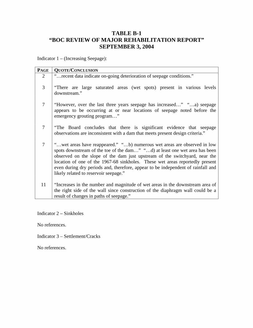
TABLE B-1 “BOC REVIEW OF MAJOR REHABILITATION REPORT”
SEPTEMBER 3, 2004 Indicator 1 – (Increasing Seepage): PAGE QUOTE/CONCLUSION
2 “…recent data indicate on-going deterioration of seepage conditions.” 3 “There are large saturated areas (wet spots) present in various levels
downstream.” 7 “However, over the last three years seepage has increased…” “…a) seepage
appears to be occurring at or near locations of seepage noted before the emergency grouting program…”
7 “The Board concludes that there is significant evidence that seepage
observations are inconsistent with a dam that meets present design criteria.” 7 “…wet areas have reappeared.” “…b) numerous wet areas are observed in low
spots downstream of the toe of the dam…” “…d) at least one wet area has been observed on the slope of the dam just upstream of the switchyard, near the location of one of the 1967-68 sinkholes. These wet areas reportedly present even during dry periods and, therefore, appear to be independent of rainfall and likely related to reservoir seepage.”
11 “Increases in the number and magnitude of wet areas in the downstream area of
the right side of the wall since construction of the diaphragm wall could be a result of changes in paths of seepage.”
Indicator 2 – Sinkholes No references. Indicator 3 – Settlement/Cracks No references.
Indicator 4 – Soft Areas/Zones PAGE QUOTE/CONCLUSION
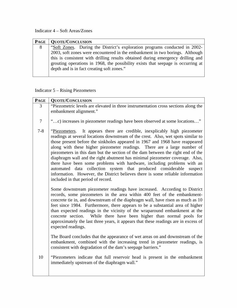
8 “Soft Zones. During the District’s exploration programs conducted in 2002-2003, soft zones were encountered in the embankment in two borings. Although this is consistent with drilling results obtained during emergency drilling and grouting operations in 1968, the possibility exists that seepage is occurring at depth and is in fact creating soft zones.”
Indicator 5 – Rising Piezometers PAGE QUOTE/CONCLUSION
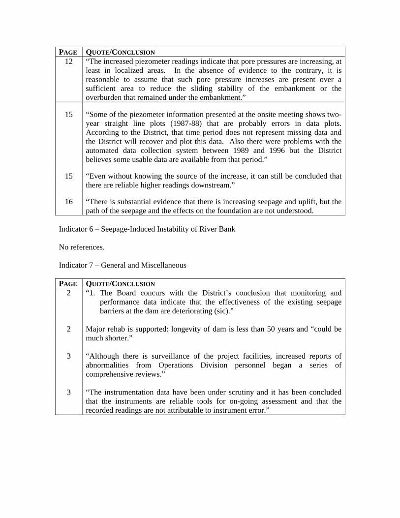
3 “Piezometric levels are elevated in three instrumentation cross sections along the embankment alignment.”
7 “…c) increases in piezometer readings have been observed at some locations…”
7-8 “Piezometers. It appears there are credible, inexplicably high piezometer readings at several locations downstream of the crest. Also, wet spots similar to those present before the sinkholes appeared in 1967 and 1968 have reappeared along with these higher piezometer readings. There are a large number of piezometers in this dam but the section of the dam between the right end of the diaphragm wall and the right abutment has minimal piezometer coverage. Also, there have been some problems with hardware, including problems with an automated data collection system that produced considerable suspect information. However, the District believes there is some reliable information included in that period of record. Some downstream piezometer readings have increased. According to District records, some piezometers in the area within 400 feet of the embankment-concrete tie in, and downstream of the diaphragm wall, have risen as much as 10 feet since 1984. Furthermore, there appears to be a substantial area of higher than expected readings in the vicinity of the wraparound embankment at the concrete section. While there have been higher than normal pools for approximately the last three years, it appears that these readings are in excess of expected readings. The Board concludes that the appearance of wet areas on and downstream of the embankment, combined with the increasing trend in piezometer readings, is consistent with degradation of the dam’s seepage barriers.”
10 “Piezometers indicate that full reservoir head is present in the embankment
immediately upstream of the diaphragm wall.”
PAGE QUOTE/CONCLUSION 12 “The increased piezometer readings indicate that pore pressures are increasing, at
least in localized areas. In the absence of evidence to the contrary, it is reasonable to assume that such pore pressure increases are present over a sufficient area to reduce the sliding stability of the embankment or the overburden that remained under the embankment.”
15 “Some of the piezometer information presented at the onsite meeting shows two-
year straight line plots (1987-88) that are probably errors in data plots. According to the District, that time period does not represent missing data and the District will recover and plot this data. Also there were problems with the automated data collection system between 1989 and 1996 but the District believes some usable data are available from that period.”
15 “Even without knowing the source of the increase, it can still be concluded that
there are reliable higher readings downstream.”
16 “There is substantial evidence that there is increasing seepage and uplift, but the path of the seepage and the effects on the foundation are not understood.
Indicator 6 – Seepage-Induced Instability of River Bank No references. Indicator 7 – General and Miscellaneous PAGE QUOTE/CONCLUSION
2 “1. The Board concurs with the District’s conclusion that monitoring and performance data indicate that the effectiveness of the existing seepage barriers at the dam are deteriorating (sic).”
2 Major rehab is supported: longevity of dam is less than 50 years and “could be
much shorter.” 3 “Although there is surveillance of the project facilities, increased reports of
abnormalities from Operations Division personnel began a series of comprehensive reviews.”
3 “The instrumentation data have been under scrutiny and it has been concluded
that the instruments are reliable tools for on-going assessment and that the recorded readings are not attributable to instrument error.”
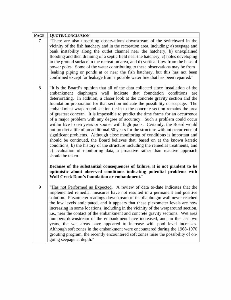
PAGE QUOTE/CONCLUSION
7 “There are also unsettling observations downstream of the switchyard in the vicinity of the fish hatchery and in the recreation area, including: a) seepage and bank instability along the outlet channel near the hatchery, b) unexplained flooding and then draining of a septic field near the hatchery, c) holes developing in the ground surface in the recreation area, and d) vertical flow from the base of power poles. Some of the water contributing to these observations may be from leaking piping or ponds at or near the fish hatchery, but this has not been confirmed except for leakage from a potable water line that has been repaired.”
8 “It is the Board’s opinion that all of the data collected since installation of the
embankment diaphragm wall indicate that foundation conditions are deteriorating. In addition, a closer look at the concrete gravity section and the foundation preparation for that section indicate the possibility of seepage. The embankment wraparound section tie-in to the concrete section remains the area of greatest concern. It is impossible to predict the time frame for an occurrence of a major problem with any degree of accuracy. Such a problem could occur within five to ten years or sooner with high pools. Certainly, the Board would not predict a life of an additional 50 years for the structure without occurrence of significant problems. Although close monitoring of conditions is important and should be continued, the Board believes that, based on a) the known karstic conditions, b) the history of the structure including the remedial treatments, and c) evaluation of monitoring data, a proactive rather than reactive approach should be taken. Because of the substantial consequences of failure, it is not prudent to be optimistic about observed conditions indicating potential problems with Wolf Creek Dam’s foundation or embankment.”
9 “Has not Performed as Expected. A review of data to-date indicates that the
implemented remedial measures have not resulted in a permanent and positive solution. Piezometer readings downstream of the diaphragm wall never reached the low levels anticipated, and it appears that these piezometer levels are now increasing in some locations, including in the vicinity of the wraparound section, i.e., near the contact of the embankment and concrete gravity sections. Wet area numbers downstream of the embankment have increased, and, in the last two years, the wet areas have appeared to increase with pool level increases. Although soft zones in the embankment were encountered during the 1968-1970 grouting program, the recently encountered soft zones raise the possibility of on-going seepage at depth.”
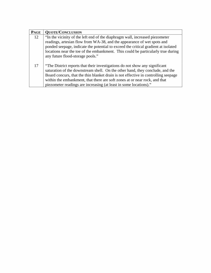
PAGE QUOTE/CONCLUSION
12 “In the vicinity of the left end of the diaphragm wall, increased piezometer readings, artesian flow from WA-38, and the appearance of wet spots and ponded seepage, indicate the potential to exceed the critical gradient at isolated locations near the toe of the embankment. This could be particularly true during any future flood-storage pools.”
17 “The District reports that their investigations do not show any significant
saturation of the downstream shell. On the other hand, they conclude, and the Board concurs, that the thin blanket drain is not effective in controlling seepage within the embankment, that there are soft zones at or near rock, and that piezometer readings are increasing (at least in some locations).”
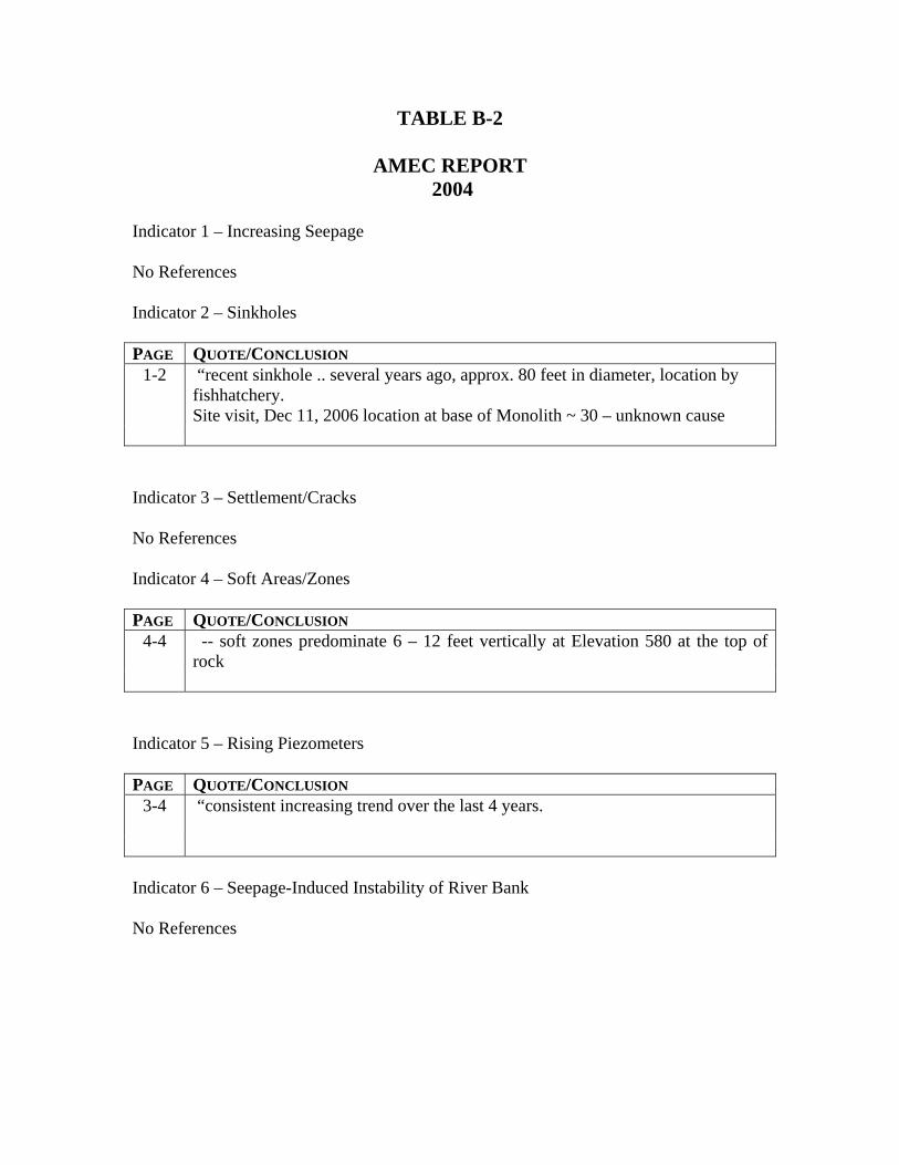
TABLE B-2
AMEC REPORT 2004
Indicator 1 – Increasing Seepage No References Indicator 2 – Sinkholes PAGE QUOTE/CONCLUSION
1-2 “recent sinkhole .. several years ago, approx. 80 feet in diameter, location by fishhatchery. Site visit, Dec 11, 2006 location at base of Monolith ~ 30 – unknown cause
Indicator 3 – Settlement/Cracks No References Indicator 4 – Soft Areas/Zones PAGE QUOTE/CONCLUSION
4-4
-- soft zones predominate 6 – 12 feet vertically at Elevation 580 at the top of rock
Indicator 5 – Rising Piezometers PAGE QUOTE/CONCLUSION
3-4 “consistent increasing trend over the last 4 years.
Indicator 6 – Seepage-Induced Instability of River Bank No References
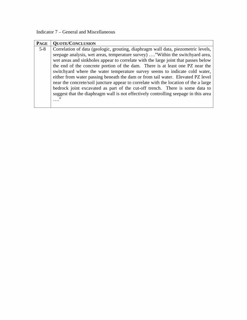
Indicator 7 – General and Miscellaneous PAGE QUOTE/CONCLUSION
5-8 Correlation of data (geologic, grouting, diaphragm wall data, piezometric levels, seepage analysis, wet areas, temperature survey) ….”Within the switchyard area, wet areas and sinkholes appear to correlate with the large joint that passes below the end of the concrete portion of the dam. There is at least one PZ near the switchyard where the water temperature survey seems to indicate cold water, either from water passing beneath the dam or from tail water. Elevated PZ level near the concrete/soil juncture appear to correlate with the location of the a large bedrock joint excavated as part of the cut-off trench. There is some data to suggest that the diaphragm wall is not effectively controlling seepage in this area ….”
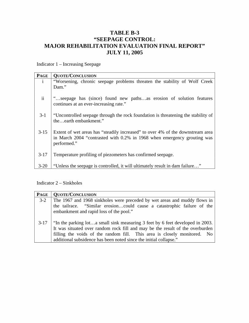
TABLE B-3 “SEEPAGE CONTROL:
MAJOR REHABILITATION EVALUATION FINAL REPORT” JULY 11, 2005
Indicator 1 – Increasing Seepage PAGE QUOTE/CONCLUSION
i “Worsening, chronic seepage problems threaten the stability of Wolf Creek Dam.”
ii “…seepage has (since) found new paths…as erosion of solution features
continues at an ever-increasing rate.”
3-1 “Uncontrolled seepage through the rock foundation is threatening the stability of the…earth embankment.”
3-15 Extent of wet areas has “steadily increased” to over 4% of the downstream area
in March 2004 “contrasted with 0.2% in 1968 when emergency grouting was performed.”
3-17 Temperature profiling of piezometers has confirmed seepage.
3-20 “Unless the seepage is controlled, it will ultimately result in dam failure…”
Indicator 2 – Sinkholes PAGE QUOTE/CONCLUSION
3-2 The 1967 and 1968 sinkholes were preceded by wet areas and muddy flows in the tailrace. “Similar erosion…could cause a catastrophic failure of the embankment and rapid loss of the pool.”
3-17 “In the parking lot…a small sink measuring 3 feet by 6 feet developed in 2003.
It was situated over random rock fill and may be the result of the overburden filling the voids of the random fill. This area is closely monitored. No additional subsidence has been noted since the initial collapse.”
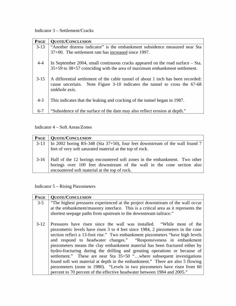
Indicator 3 – Settlement/Cracks PAGE QUOTE/CONCLUSION 3-13
“Another distress indicator” is the embankment subsidence measured near Sta 37+00. The settlement rate has increased since 1997.
4-4 In September 2004, small continuous cracks appeared on the road surface – Sta.
35+59 to 38+57 coinciding with the area of maximum embankment settlement.
3-15 A differential settlement of the cable tunnel of about 1 inch has been recorded: cause uncertain. Note Figure 3-10 indicates the tunnel to cross the 67-68 sinkhole axis.
4-3 This indicates that the leaking and cracking of the tunnel began in 1987.
6-7 “Subsidence of the surface of the dam may also reflect erosion at depth.”
Indicator 4 – Soft Areas/Zones PAGE QUOTE/CONCLUSION 3-13
In 2002 boring RS-348 (Sta 37+50), four feet downstream of the wall found 7 feet of very soft saturated material at the top of rock.
3-16 Half of the 12 borings encountered soft zones in the embankment. Two other
borings over 100 feet downstream of the wall in the cone section also encountered soft material at the top of rock.
Indicator 5 – Rising Piezometers PAGE QUOTE/CONCLUSION
3-5 “The highest pressures experienced at the project downstream of the wall occur at the embankment/masonry interface. This is a critical area as it represents the shortest seepage paths from upstream to the downstream tailrace.”
3-12 Pressures have risen since the wall was installed. “While most of the
piezometric levels have risen 3 to 4 feet since 1984, 2 piezometers in the cone section reflect a 13-foot rise.” Two embankment piezometers “have high levels and respond to headwater changes.” “Responsiveness in embankment piezometers means the clay embankment material has been fractured either by hydro-fracturing during the drilling and grouting operations or because of settlement.” These are near Sta 35+50 “…where subsequent investigations found soft wet material at depth in the embankment.” There are also 5 flowing piezometers (none in 1980). “Levels in two piezometers have risen from 60 percent to 70 percent of the effective headwater between 1984 and 2005.”

Indicator 6 – Seepage-Induced Instability of River Bank PAGE QUOTE/CONCLUSION 3-16
About 1,800 feet downstream of the dam, the bank has become unstable over a 300-foot length because of seepage. Seepage first noted in 2002
Indicator 7 – General and Miscellaneous PAGE QUOTE/CONCLUSION
(i) “Key instrumentation readings, persistent and increasing wet areas, and investigative borings that encountered very soft, wet material at depth in the embankment all confirm solution features (still) exist that have not been cut off.”
(i) The dam is judged to be in the “progression” stage, “…and without timely
intervention will result in a breach of the embankment.”
(ii) “…piping can rapidly progress with little or no warning to a point that precludes successful intervention.”
(ii) “Failure would be catastrophic.” (Page 1 mentions 3 billion dollars and over 100
lives.)
(ii) “Given the substantial consequences of complete loss or impaired operation of the dam, the history of problems, leaking foundation conditions and failure mechanisms at work, Nashville District has serious concerns about the reliability of the dam.”
(ii) Construction of a new cut-off wall is judged “imperative” by Nashville District.
3-1 “The subsurface investigation and other indicators of distress confirm solution
features still exist…and are progressively opening up as erosion of the filling occurs.” This erosion is felt to be occurring “at an ever-increasing rate.”
3-18 Refer to Figure 3-11.
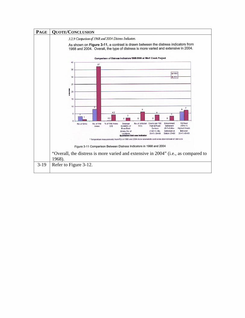
PAGE QUOTE/CONCLUSION
“Overall, the distress is more varied and extensive in 2004” (i.e., as compared to 1968).
3-19 Refer to Figure 3-12.
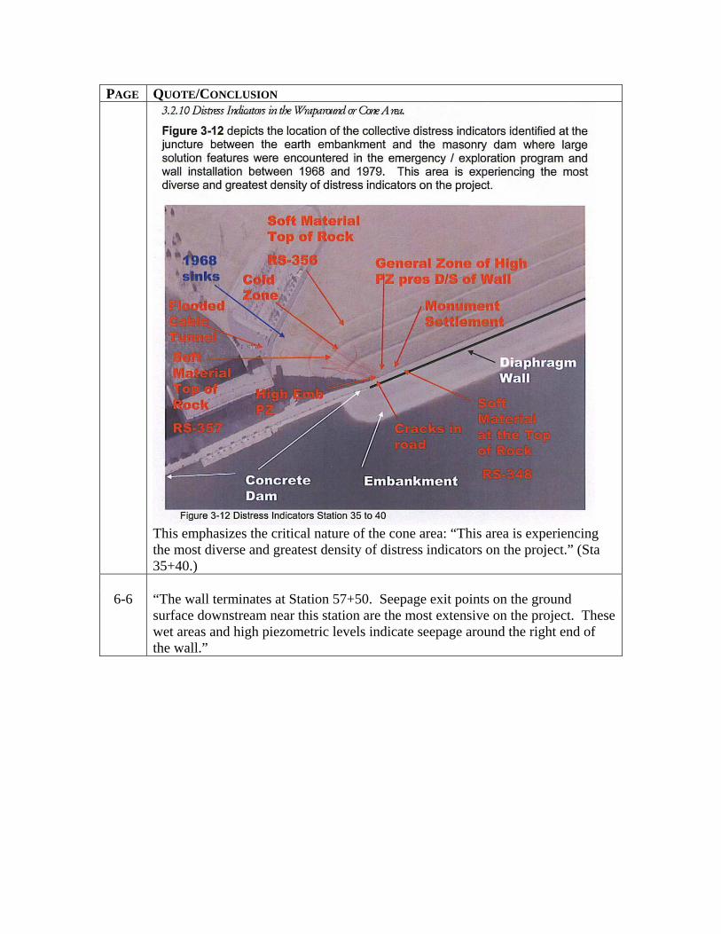
PAGE QUOTE/CONCLUSION
This emphasizes the critical nature of the cone area: “This area is experiencing the most diverse and greatest density of distress indicators on the project.” (Sta 35+40.)
6-6 “The wall terminates at Station 57+50. Seepage exit points on the ground
surface downstream near this station are the most extensive on the project. These wet areas and high piezometric levels indicate seepage around the right end of the wall.”

TABLE B-4
AMEC POWERPOINT PRESENTATION 2006
Indicator 1 – Increasing Seepage SLIDE QUOTE/CONCLUSION
10 “wet areas have redeveloped” post diaphragm wall construction. Photographs of areas slide # 35
22 “Seepage beneath Monolith 36 & 37 continues” post diaphragm wall
construction.
55 “confirm .. what was buried in details” – “Karst joints and weathered zones in wraparound section and switchyard appear to contributing to continued seepage …” “Worsening, chronic seepage problems threaten the stability of Wolf Creek Dam.”
Indicator 2 – Sinkholes No references Indicator 3 – Settlement/Cracks SLIDE QUOTE/CONCLUSION
10
Increase in rate of settlement – 0.15 feet in 16 years and 0.15 feet in the subsequent 7 years post wall construction.
11 Picture dated 9/20/2004 showing depression in roadway and guard rail and asphalt patch at monolith 37 & embankment contact.
Indicator 4 – Soft Areas/Zones No References Indicator 5 – Rising Piezometers
SLIDE QUOTE/CONCLUSION
10 “increase in 2 piezometers in wrap around section rising by 13 feet since 1984. tailrace.”
26 “Rising water levels within embankment with highest levels nearest Monolith 37.
27 “History suggests the higher piezometric readings of the last 3-5 years are independent of pool elevations. “The highest pressures experienced at the project downstream of the wall occur at the embankment/masonry interface. This is a critical area as it represents the shortest seepage paths from upstream to the downstream.
Indicator 6 – Seepage-Induced Instability of River Bank No References Indicator 7 – General and Miscellaneous SLIDE QUOTE/CONCLUSION
32 Volume of grout was 3 X theoretical volume of drilled holes.
33 Effectiveness of secondary diaphragm is doubted. “Key instrumentation readings, persistent and increasing wet areas, and investigative borings that encountered very soft, wet material at depth in the embankment all confirm solution features (still) exist that have not been cut off.”
6-6 “The wall terminates at Station 57+50. Seepage exit points on the ground
surface downstream near this station are the most extensive on the project. These wet areas and high piezometric levels indicate seepage around the right end of the wall.”
TABLE B-5
STAFF POWERPOINT PRESENTATIONS TO PANEL OCTOBER 10, 2006
Indicator 1 – Increasing Seepage SLIDE QUOTE/CONCLUSION
26 Wet Areas – listed as a distress indicator
28 Wet Areas – Wet areas have increased in the last two years and are considerably more extensive than those identified in 1967-68
32 • Cool Spots from Piezometer Temp. Survey
• Cable Tunnel Seepage and Cracking • Increased Seepage and Instability Problems in the D/S Riverbank • Structural Integrity of Existing Wall
33 • Seepage coming around ends of wall • Through features untreated beneath monoliths • Around right end where no wall exists
• Below wall through features untreated or partially treated by previous grouting
• Through defects in wall itself
Indicator 2 – Sinkholes No References
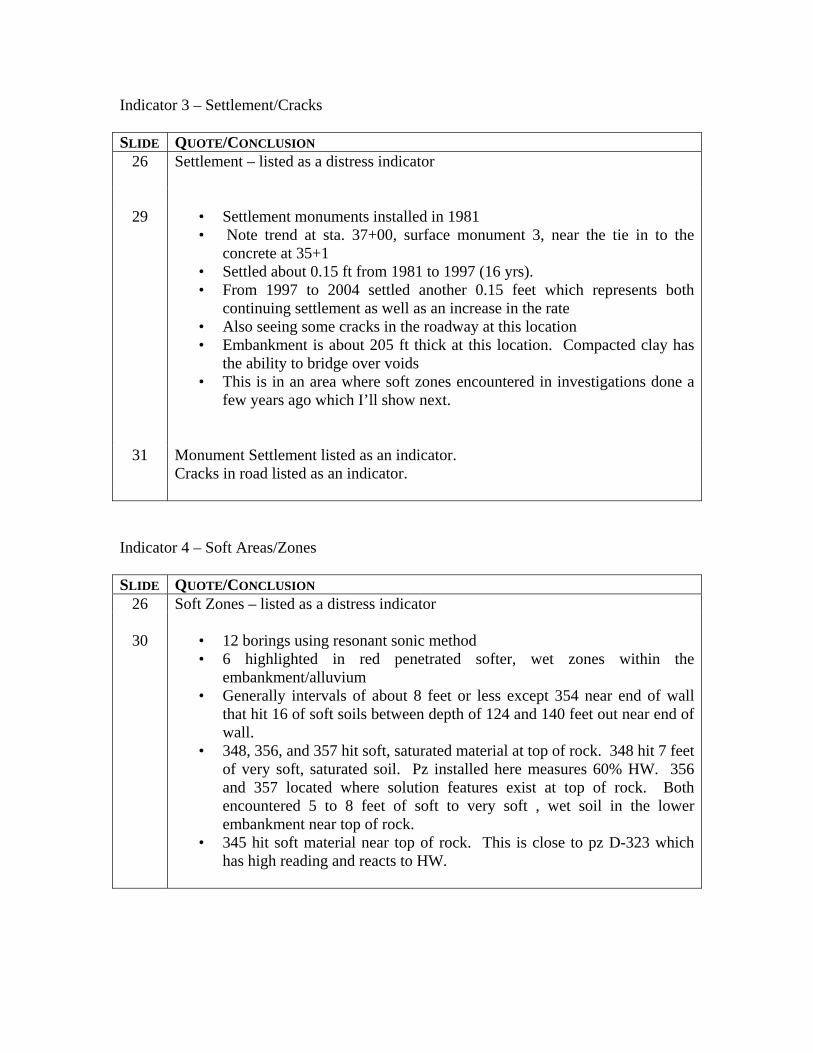
Indicator 3 – Settlement/Cracks SLIDE QUOTE/CONCLUSION
26
Settlement – listed as a distress indicator
29 • Settlement monuments installed in 1981
• Note trend at sta. 37+00, surface monument 3, near the tie in to the concrete at 35+1
• Settled about 0.15 ft from 1981 to 1997 (16 yrs). • From 1997 to 2004 settled another 0.15 feet which represents both
continuing settlement as well as an increase in the rate • Also seeing some cracks in the roadway at this location • Embankment is about 205 ft thick at this location. Compacted clay has
the ability to bridge over voids • This is in an area where soft zones encountered in investigations done a
few years ago which I’ll show next.
31 Monument Settlement listed as an indicator.
Cracks in road listed as an indicator.
Indicator 4 – Soft Areas/Zones SLIDE QUOTE/CONCLUSION
26 Soft Zones – listed as a distress indicator
30 • 12 borings using resonant sonic method • 6 highlighted in red penetrated softer, wet zones within the
embankment/alluvium • Generally intervals of about 8 feet or less except 354 near end of wall
that hit 16 of soft soils between depth of 124 and 140 feet out near end of wall.
• 348, 356, and 357 hit soft, saturated material at top of rock. 348 hit 7 feet of very soft, saturated soil. Pz installed here measures 60% HW. 356 and 357 located where solution features exist at top of rock. Both encountered 5 to 8 feet of soft to very soft , wet soil in the lower embankment near top of rock.
• 345 hit soft material near top of rock. This is close to pz D-323 which has high reading and reacts to HW.
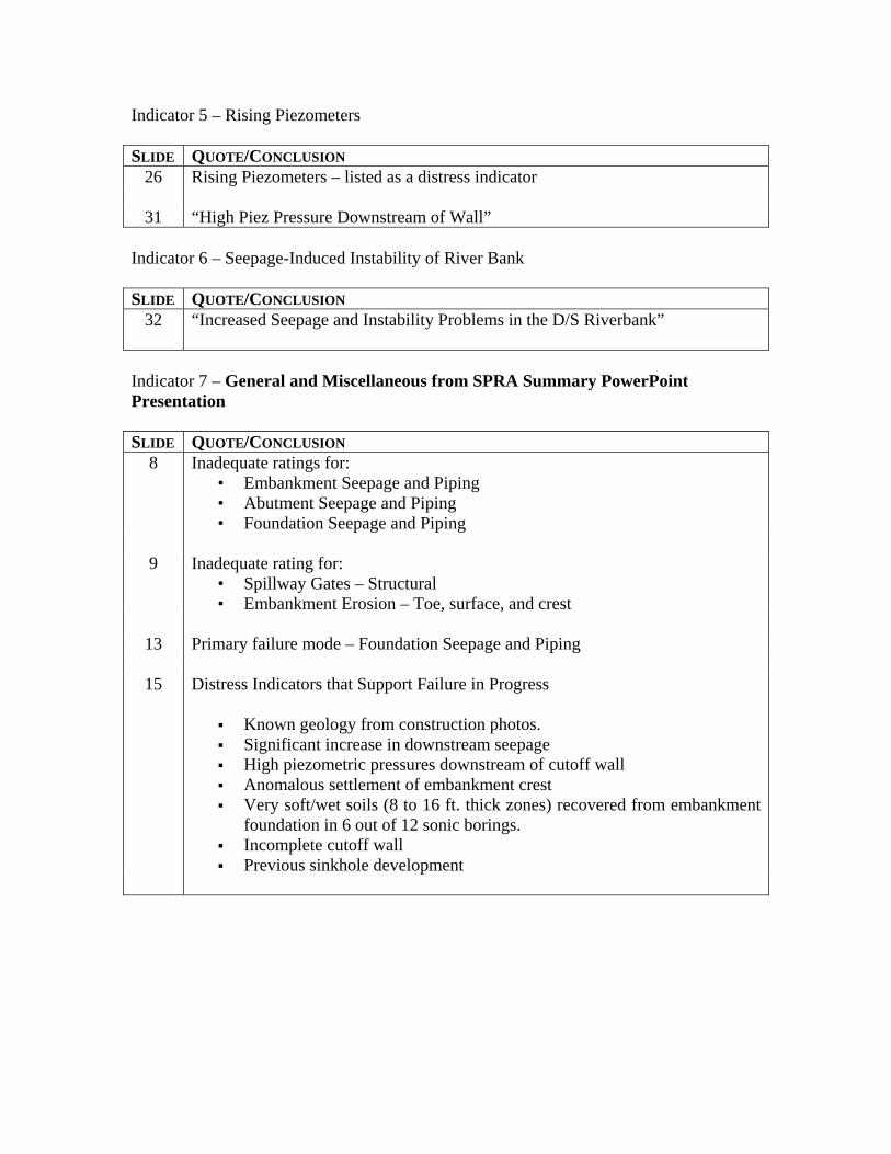
Indicator 5 – Rising Piezometers SLIDE QUOTE/CONCLUSION
26 Rising Piezometers – listed as a distress indicator
31 “High Piez Pressure Downstream of Wall” Indicator 6 – Seepage-Induced Instability of River Bank SLIDE QUOTE/CONCLUSION
32
“Increased Seepage and Instability Problems in the D/S Riverbank”
Indicator 7 – General and Miscellaneous from SPRA Summary PowerPoint Presentation SLIDE QUOTE/CONCLUSION
8 Inadequate ratings for: • Embankment Seepage and Piping • Abutment Seepage and Piping • Foundation Seepage and Piping
9 Inadequate rating for:
• Spillway Gates – Structural • Embankment Erosion – Toe, surface, and crest
13 Primary failure mode – Foundation Seepage and Piping
15 Distress Indicators that Support Failure in Progress
Known geology from construction photos. Significant increase in downstream seepage High piezometric pressures downstream of cutoff wall Anomalous settlement of embankment crest Very soft/wet soils (8 to 16 ft. thick zones) recovered from embankment
foundation in 6 out of 12 sonic borings. Incomplete cutoff wall Previous sinkhole development

Wolf Creek Dam Consensus Report Engineering Risk and Reliability Analysis Peer Review – Dam Safety Action Classification Group 1 April 11, 2007
Attachment C
Site Visit Photos Referenced in Consensus Report
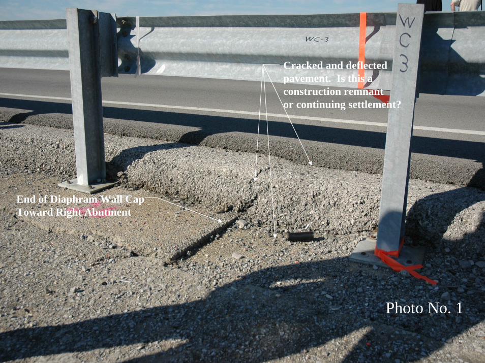
End of Diaphram Wall CapToward Right Abutment
Cracked and deflectedpavement. Is this a construction remnant or continuing settlement?
Photo No. 1
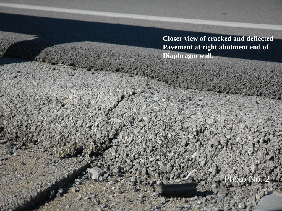
Closer view of cracked and deflectedPavement at right abutment end ofDiaphragm wall.
Photo No. 2
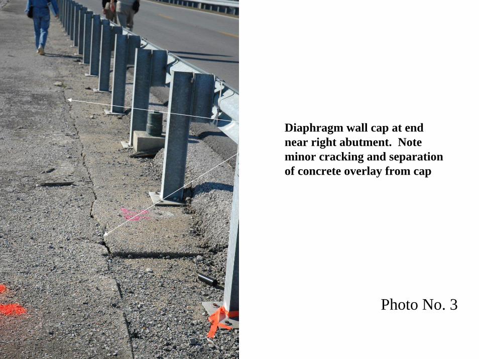
Diaphragm wall cap at endnear right abutment. Noteminor cracking and separation of concrete overlay from cap
Photo No. 3
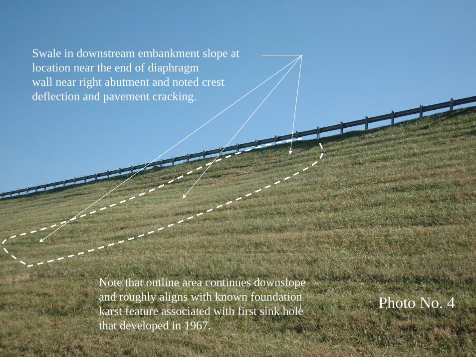
Swale in downstream embankment slope at location near the end of diaphragm wall near right abutment and noted crestdeflection and pavement cracking.
Photo No. 4Note that outline area continues downslopeand roughly aligns with known foundationkarst feature associated with first sink holethat developed in 1967.
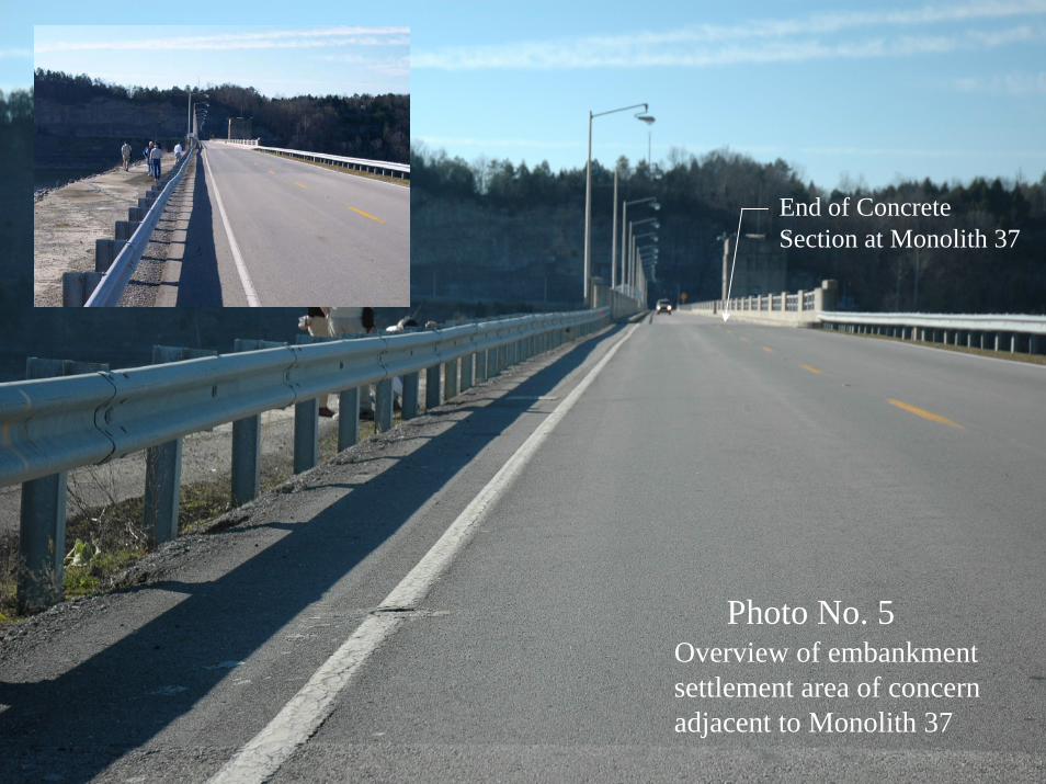
Photo No. 5Overview of embankmentsettlement area of concernadjacent to Monolith 37
End of ConcreteSection at Monolith 37
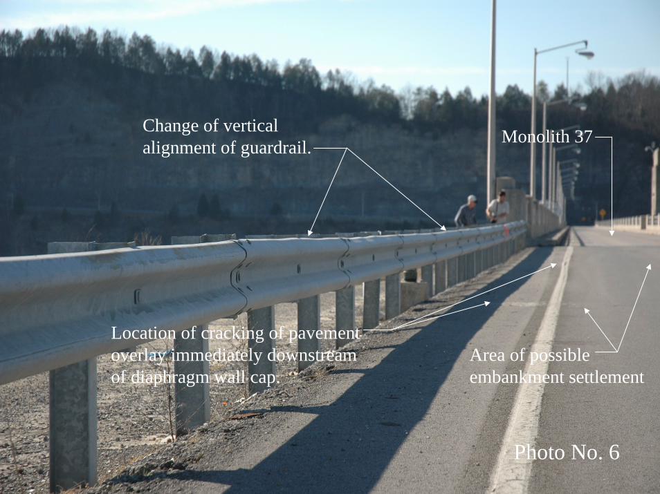
Photo No. 6
Location of cracking of pavementoverlay immediately downstreamof diaphragm wall cap.
Change of vertical alignment of guardrail. Monolith 37
Area of possible embankment settlement
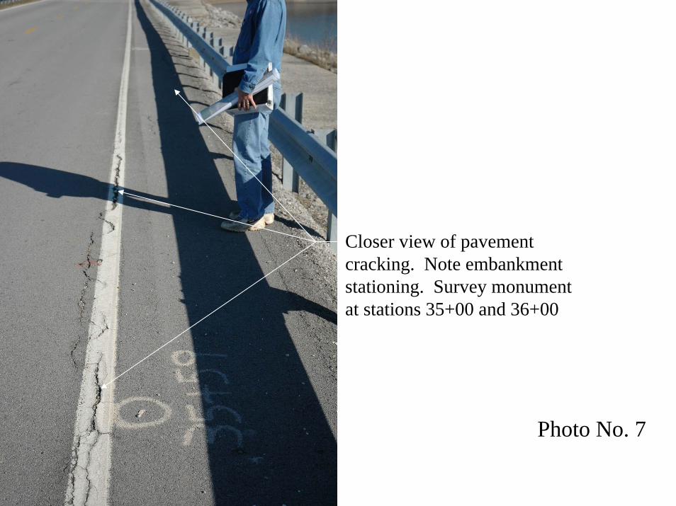
Photo No. 7
Closer view of pavementcracking. Note embankmentstationing. Survey monumentat stations 35+00 and 36+00
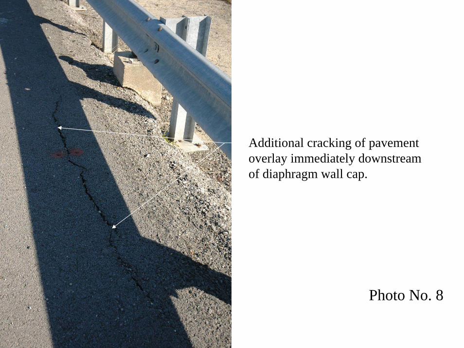
Photo No. 8
Additional cracking of pavementoverlay immediately downstreamof diaphragm wall cap.
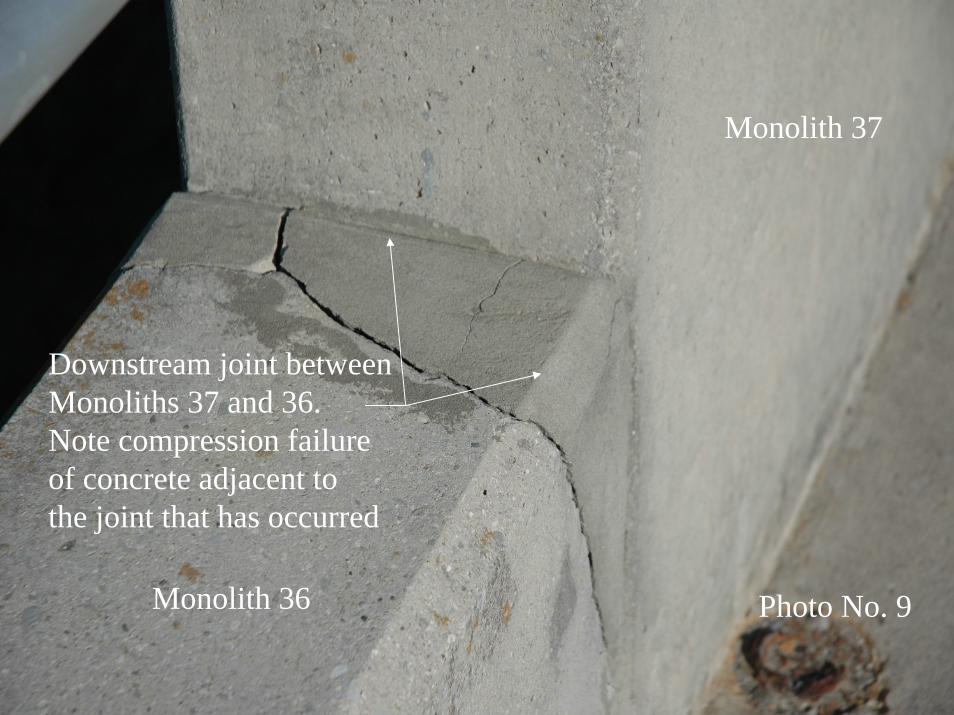
Photo No. 9
Monolith 37
Monolith 36
Downstream joint between Monoliths 37 and 36. Note compression failureof concrete adjacent tothe joint that has occurred
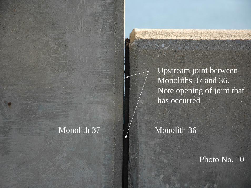
Photo No. 10
Upstream joint between Monoliths 37 and 36. Note opening of joint thathas occurred
Monolith 37 Monolith 36
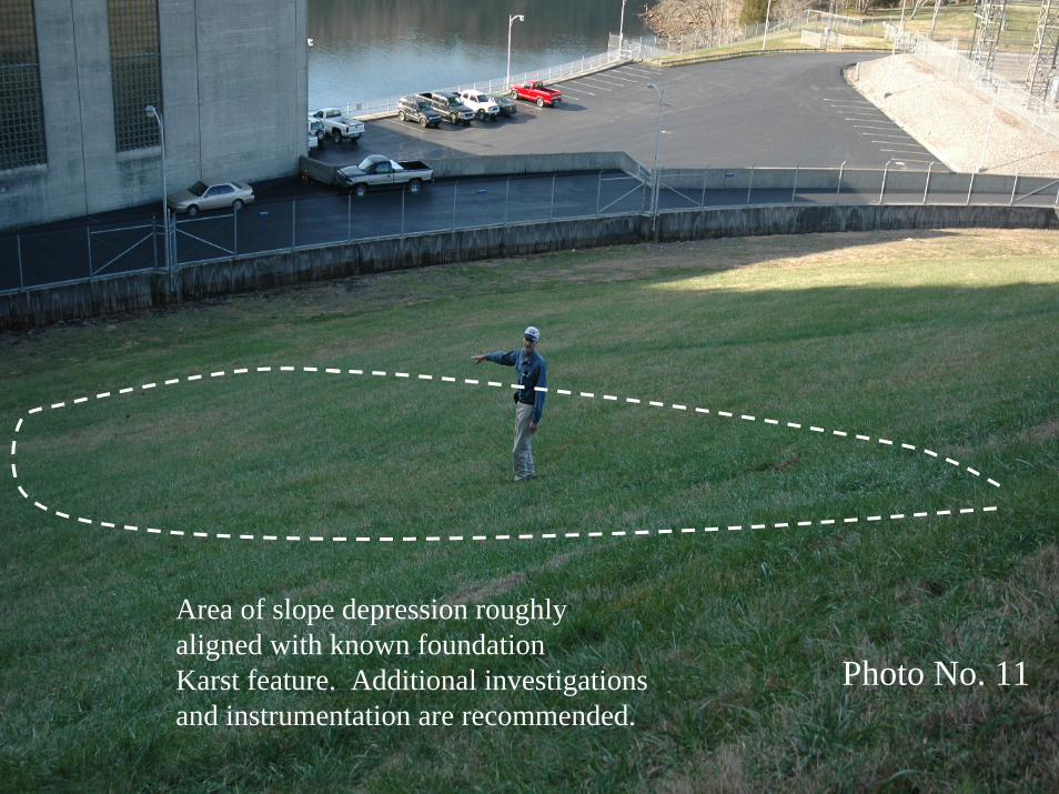
Photo No. 11
Area of slope depression roughlyaligned with known foundationKarst feature. Additional investigationsand instrumentation are recommended.
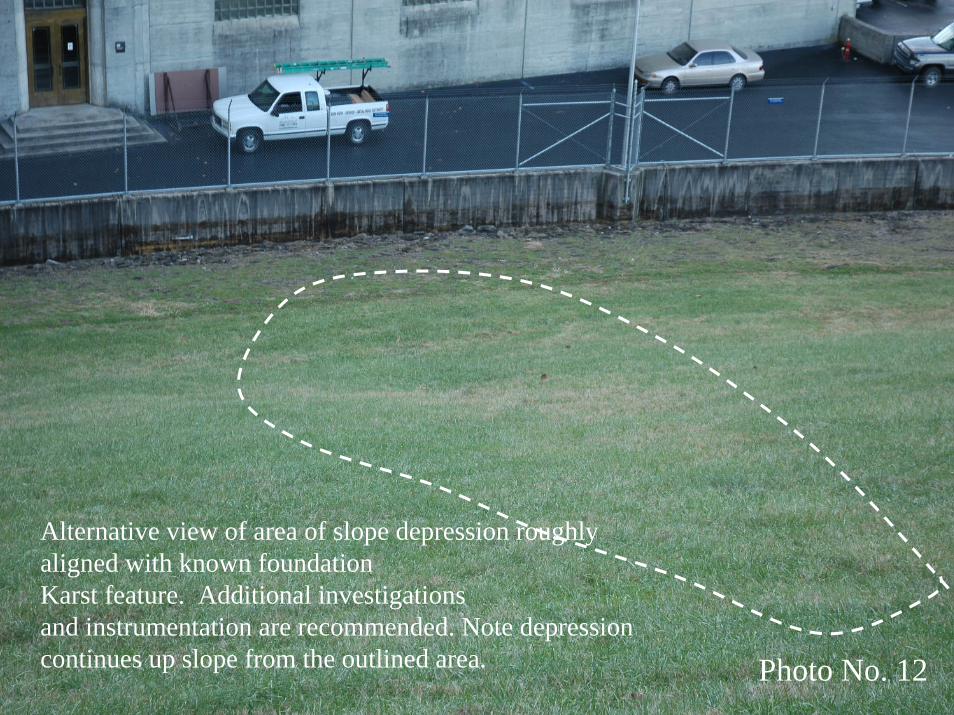
Photo No. 12
Alternative view of area of slope depression roughlyaligned with known foundationKarst feature. Additional investigationsand instrumentation are recommended. Note depressioncontinues up slope from the outlined area.
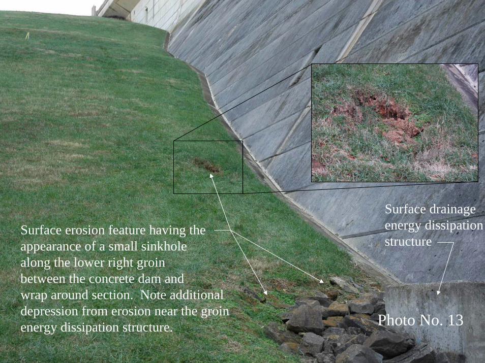
Photo No. 13
Surface erosion feature having the appearance of a small sinkhole along the lower right groinbetween the concrete dam and wrap around section. Note additionaldepression from erosion near the groinenergy dissipation structure.
Surface drainageenergy dissipationstructure
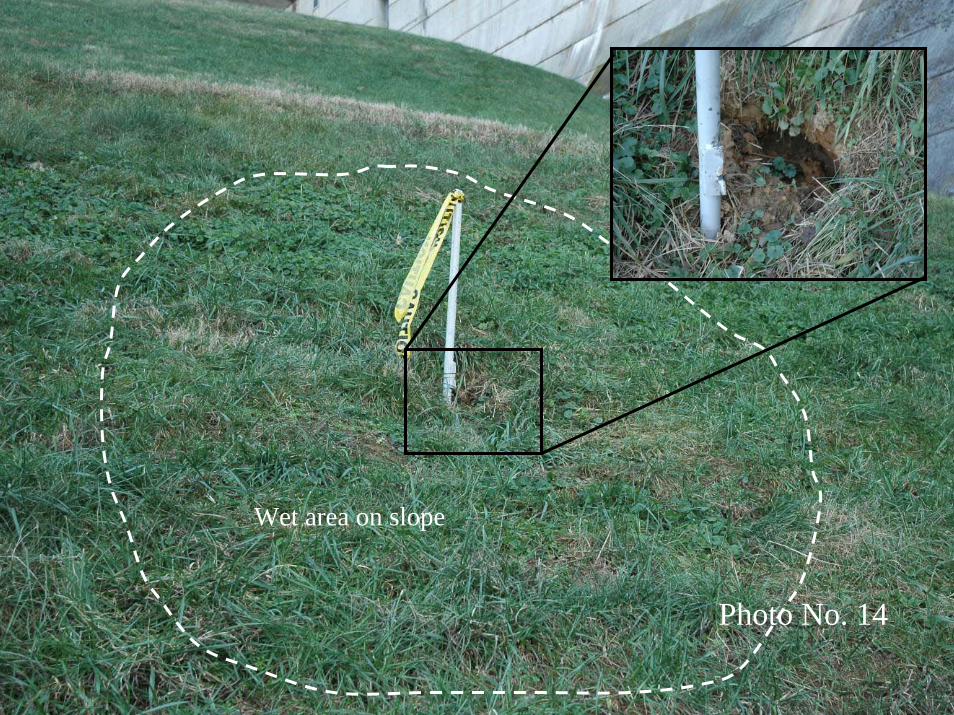
Photo No. 14
Wet area on slope
Wolf Creek Dam Consensus Report Engineering Risk and Reliability Analysis Peer Review – Dam Safety Action Classification Group 1 April 11, 2007
Attachment D
Alternative Description of Events Leading to the Development of the Critical Embankment Foundation Seepage and Piping Failure Mode
Wolf Creek Dam Consensus Report Engineering Risk and Reliability Analysis Peer Review – Dam Safety Action Classification Group 1 April 11, 2007
Alternative Description of Events Leading to the Development of the Critical Embankment Foundation Seepage and Piping Failure Mode
The limestone foundation rock prior to construction was riddled with both open and soil filled voids (Karst) causes by millions of years of solutioning activity by ground water. These Karst features typically followed joints in the rock. The depth of individual Karst features along the near vertical joints has been measured to be as much as 40 feet. The width of the Karst features, based on examination of construction photographs and other available information appears range from fractions of an inch to as large as 30 feet. The soil-filled Karst features may contain some voids that substantially reduce seepage path lengths between the reservoir and the free discharge face in areas downstream of the dam. There are two attributes of Karst bedrock that may contribute to the development of a piping failure mode. First and of primary concern, seepage pressures (typically ranging from 175 to 200 feet) and corresponding seepage flows that develop through the Karst features and the adjacent fractured rock can begin to erode soil, filling the Karst voids at the discharge face. Observations at the site indicated that soils in Karst features beneath the dam have been eroded over time and that piping has initiated. The second, and secondary attribute if it occurs, is dissolutioning of the bedrock. Unlike piping, dissolutioning of the bedrock begins where reservoir water enters the foundation in the reservoir. Dissolutioning occurs as seepage flows develop through non-grouted joints. The solutioning opens the joints, and over time, the amount of flow and corresponding water pressures in the bedrock begin to increase in the downstream direction. Under the right circumstances, the rate of dissolutioning can be accelerated at locations where seepage gradients are high (such as the base of a cutoff wall, or through defects in the diaphragm wall or grout curtain). The continuation phase of a piping failure mode through the Karst foundation can therefore be impacted by these potentially complimentary factors. Without dissolutioning, the rate of piping would generally increase and the continuation of void opening and formation would accelerate with time. If dissolutioning is also happening, water pressures and flow quantities are increasing toward the pipe from the upstream direction causing a further acceleration of the failure mode development. The piping that has occurred in the foundation of Wolf Creek dam has led to loss of cavity wall and roof support, and collapse (as evidenced by the occurrence of sinkholes near the downstream toe of the embankment at two different locations). Erosion of Karst infilling has likely continued in many locations to the base of the foundation soils and embankment (as evidenced by the soft zones that have been encountered in recent exploration borings). As the erosion continues upstream to, under, and potentially through the grout curtain and cutoff wall, there will be a time when there would likely be a dramatic increase in the rate of flow through potentially large voids. The large flows that would occur at this time would be capable of carrying large quantities of materials allowing for the rapid growth (progression)

Wolf Creek Dam Consensus Report Engineering Risk and Reliability Analysis Peer Review – Dam Safety Action Classification Group 1 April 11, 2007
of sinkholes in the dam, loss of support for the cutoff wall, failure of the cutoff wall and then rapid breach formation. The flow rates that would likely occur at the stage when convergence of the piping and dissolutioning processes occur would also likely preclude or substantially reduce the potential effectiveness of any heroic intervention to prevent ultimate breach formation and failure of the dam.