Peer Control Data Interface Implementation Guide · PDF filex Experion LX Peer Control Data...
136
Experion LX Peer Control Data Interface Implementation Guide EXDOC-XX84-en-110A R110 February 2014 Release 110 Honeywell
Transcript of Peer Control Data Interface Implementation Guide · PDF filex Experion LX Peer Control Data...
Experion LX
Peer Control Data Interface Implementation Guide
EXDOC-XX84-en-110A R110
February 2014
Release 110 Honeywell

ii Experion LX Peer Control Data Interface Implementation Guide R110 Honeywell February 2014
Notices and Trademarks
Copyright 2014 by Honeywell International Sárl. Release 110 February, 2014
While this information is presented in good faith and believed to be accurate, Honeywell disclaims the implied warranties of merchantability and fitness for a particular purpose and makes no express warranties except as may be stated in its written agreement with and for its customers.
In no event is Honeywell liable to anyone for any indirect, special or consequential damages. The information and specifications in this document are subject to change without notice.
Honeywell Experion PKS, Experion® LX are registered trademarks of Honeywell International Inc.
Other brand or product names are trademarks of their respective owners.
Honeywell Process Solutions
1860 W. Rose Garden Lane
Phoenix, AZ 85027 USA
1-800 822-7673
R110 Experion LX Peer Control Data Interface Implementation Guide iii February 2014 Honeywell
About This Document
Scope This Guide provides information about using the licensed Peer Control Data Interface (PCDI) function to interface Safety Manager or third-party peer devices supporting MODBUS TCP communications with the Experion LX C300 Controller. It includes planning, installing, configuring, operating, and troubleshooting type data as well as some general conceptual type data to help understand the purpose of the PCDI function.
Intended audience Personnel who are responsible for interfacing Safety Manager or third-party peer devices for peer-to-peer communications through the peer control data interface with Experion LX control strategies.
Prerequisite skills • Familiar with working in a Windows operating environment.
• Familiar with using these Experion LX applications:
− Configuration Studio
− Control Builder
− Station
− Safety Manager
− Safety Builder
• Familiar with MODBUS TCP communications protocol.
How to use this guide Choose a topic associated with the task you want to complete from the table of contents and click it to launch the topic.
Support and Other Contacts
iv Experion LX Peer Control Data Interface Implementation Guide R110 Honeywell February 2014
Release Information
Document Name Document ID
Release Number
Publication Date
Peer Control Data Interface Implementation Guide -
EXDOC-XX84-en-110A
110 July 2011
Document Category
Configuration
References The following list identifies all documents that may be sources of reference for material discussed in this publication.
Document Title
In Control Building Guide
In Control Builder Components Reference
In Control Builder Parameter Reference
In Control Builder Error Codes Reference
In Fault Tolerant Ethernet Overview and Implementation Guide
In Fault Tolerant Ethernet Installation and Service Guide
In Configuration Studio Overview
In Operator's Guide
Support and Other Contacts
R110 Experion LX Peer Control Data Interface Implementation Guide v February 2014 Honeywell
Support and Other Contacts
People’s Republic of China Contact:
Phone: Mail: Email:
Honeywell Global TAC – China +86- 21-2219-6888 800-820-0237 400-820-0386 Honeywell (China) Co., Ltd 33/F, Tower A, City Center, 100 Zunyi Rd. Shanghai 200051, People’s Republic of China [email protected]

Symbol Definitions
vi Experion LX Peer Control Data Interface Implementation Guide R110 Honeywell February 2014
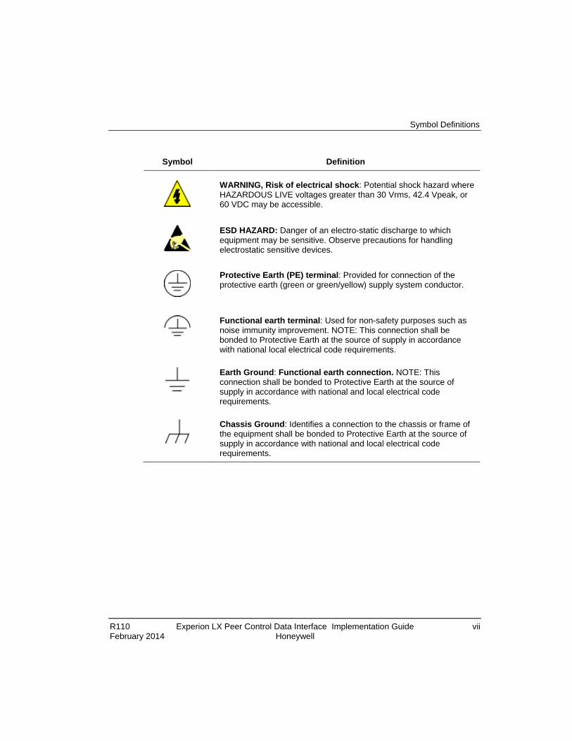
Symbol Definitions The following table lists those symbols used in this document to denote certain conditions.
Symbol Definition
ATTENTION: Identifies information that requires special consideration.
TIP: Identifies advice or hints for the user, often in terms of performing a task.
REFERENCE -EXTERNAL: Identifies an additional source of information outside of the bookset.
REFERENCE - INTERNAL: Identifies an additional source of information within the bookset.
CAUTION
Indicates a situation which, if not avoided, may result in equipment or work (data) on the system being damaged or lost, or may result in the inability to properly operate the process.
CAUTION: Indicates a potentially hazardous situation which, if not avoided, may result in minor or moderate injury. It may also be used to alert against unsafe practices.
CAUTION symbol on the equipment refers the user to the product manual for additional information. The symbol appears next to required information in the manual.
WARNING: Indicates a potentially hazardous situation, which, if not avoided, could result in serious injury or death.
WARNING symbol on the equipment refers the user to the product manual for additional information. The symbol appears next to required information in the manual.
Symbol Definitions
R110 Experion LX Peer Control Data Interface Implementation Guide vii February 2014 Honeywell
Symbol Definition
WARNING, Risk of electrical shock: Potential shock hazard where HAZARDOUS LIVE voltages greater than 30 Vrms, 42.4 Vpeak, or 60 VDC may be accessible.
ESD HAZARD: Danger of an electro-static discharge to which equipment may be sensitive. Observe precautions for handling electrostatic sensitive devices.
Protective Earth (PE) terminal: Provided for connection of the protective earth (green or green/yellow) supply system conductor.
Functional earth terminal: Used for non-safety purposes such as noise immunity improvement. NOTE: This connection shall be bonded to Protective Earth at the source of supply in accordance with national local electrical code requirements.
Earth Ground: Functional earth connection. NOTE: This connection shall be bonded to Protective Earth at the source of supply in accordance with national and local electrical code requirements.
Chassis Ground: Identifies a connection to the chassis or frame of the equipment shall be bonded to Protective Earth at the source of supply in accordance with national and local electrical code requirements.

Symbol Definitions
viii Experion LX Peer Control Data Interface Implementation Guide R110 Honeywell February 2014
R110 Experion LX Peer Control Data Interface Implementation Guide ix February 2014 Honeywell
Contents
1. PEER CONTROL DATA INTERFACE OVERVIEW ..................... 15
1.1 About Peer Control Data Interface .............................................................. 15
1.2 About MODBUS TCP ..................................................................................... 15
1.3 Peer Control Data Integration over FTE ...................................................... 16
1.4 PCDI Library ................................................................................................... 18
1.5 Basic Peer Control Data Interface Block Architecture .............................. 18
1.6 Safety Manager Integration .......................................................................... 19
1.7 Peer Control Data Interface Processing Characteristics .......................... 20
2. PEER CONTROL DATA INTERFACE PLANNING AND DESIGN23
2.1 General Planning References ...................................................................... 23
2.2 Peer Control Data Interface Requirements ................................................. 23
2.3 MODBUS System Considerations ............................................................... 23
2.4 Write option selection considerations ........................................................ 24
2.5 Performance Considerations ....................................................................... 25
2.6 Safety Manager Performance Considerations ........................................... 26
3. PEER CONTROL DATA INTERFACE INSTALLATION AND UPGRADES .......................................................................................... 29
3.1 Experion LX Software Installation ............................................................... 29
3.2 FTE Network Installation .............................................................................. 29
3.3 Hardware Installation .................................................................................... 29
3.4 Safety Manager Software Installation ......................................................... 29
3.5 General Installation Considerations and Restrictions .............................. 30
4. PEER CONTROL DATA INTERFACE CONFIGURATION .......... 31
Contents
x Experion LX Peer Control Data Interface Implementation Guide R110 Honeywell February 2014
4.1 References ..................................................................................................... 31
4.2 Adding Peer Control Data Interface Device (PCDI_MASTER) Block to Project ........................................................................................................................ 31
Prerequisites ....................................................................................................................... 31 Considerations .................................................................................................................... 31 To add PCDI_MASTER block to Project ............................................................................. 34 To configure PCDI_MASTER block in Project ..................................................................... 36
4.3 Device Supported Commands ..................................................................... 46
4.4 Assigning PCDI_Master Block to Execution Environment ....................... 48 Prerequisites ....................................................................................................................... 48 Considerations .................................................................................................................... 48 To assign PCDI_MASTER block to CEE ............................................................................. 48
4.5 Adding PCDI Array Request Channel Block to Control Module ............... 51 Prerequisites ....................................................................................................................... 51 Considerations .................................................................................................................... 51 To add MODBUS TCP array request channel block to CM ................................................. 53
4.6 Starting Element Index Values ..................................................................... 67
4.7 MODBUS loopback diagnostics and Text Array Request Channel block configuration ............................................................................................................. 69
4.8 Whole array support ...................................................................................... 70 Array write scenario ............................................................................................................. 70
4.9 Simulation support ........................................................................................ 70
4.10 Loading configuration data to the CEE ................................................... 71 Prerequisites ....................................................................................................................... 71 Considerations .................................................................................................................... 71 To load PCDI_MASTER block............................................................................................. 72 This completes the procedure to load the PCDI_MASTER block. ....................................... 73
4.11 PCDI_MASTER Block Properties Form Reference ................................. 74 Main tab parameters ........................................................................................................... 74 Module Configuration tab parameters ................................................................................. 74 Slave Configuration tab parameters .................................................................................... 76 Module Statistics tab parameters ........................................................................................ 77 Connection Statistics tab parameters .................................................................................. 80 Channel Status tab parameters ........................................................................................... 82 Server History Tab Parameters ........................................................................................... 82 Server Displays Tab Parameters ......................................................................................... 84 Control Confirmation Tab Parameters ................................................................................. 86 Identification Tab Parameters.............................................................................................. 86
4.12 Array Request Channel Block Properties Form Reference ................... 88 Main tab parameters ........................................................................................................... 88
Contents
R110 Experion LX Peer Control Data Interface Implementation Guide xi February 2014 Honeywell
Configuration tab parameters ............................................................................................... 89 Scaling/Substitution tab parameters ..................................................................................... 92 Status/Data tab parameters ................................................................................................. 94 Identification tab parameters ................................................................................................ 95 Dependencies tab parameters ............................................................................................. 96 Block pins tab parameters .................................................................................................... 96 Configuration Parameters tab parameters ........................................................................... 96 Monitoring Parameters tab parameters ................................................................................ 96 Block Preferences tab parameters ....................................................................................... 96 Template Defining tab parameters ....................................................................................... 97
5. PEER CONTROL DATA INTERFACE OPERATION ................... 99
5.1 Monitoring Peer Control Data Interface Functions through Station Displays 99
Using Station Detail displays ................................................................................................ 99 Graphical example of PCDI_MASTER block detail display .................................................. 99 Graphical example of viewing Last Error on Channel Status tab of PCDI_MASTER block in Station ................................................................................................................................ 104 Graphical example of PCDI_MASTER block in system component tree ............................ 105 Using Station System Status Display ................................................................................. 106 Graphical example of PCDI_MASTER block in Alarm pane of System Status Display ...... 106
5.2 Monitoring PCDI Functions through Monitoring Tab in Control Builder112 Activating/inactivating PCDI_MASTER device ................................................................... 112 PCDI_MASTER device block icon appearances ................................................................ 113 Control Module block icon appearances ............................................................................ 118 Monitoring/Interacting with given component/block ............................................................ 119 Monitoring PCDI related statistics through C300 block in Monitoring mode ....................... 120 Monitoring PCDI related statistics through CEEC300 block in Monitoring mode ................ 121
5.3 Initiating Switchover of Redundant Devices ............................................ 122
5.4 Checking License Details ........................................................................... 123
5.5 Response to C300 RAM Retention Restart ............................................... 123
5.6 PCDI Support for Checkpoint Save/Restore functions ........................... 123
6. PEER CONTROL DATA INTERFACE MAINTENANCE ............ 127
Periodic Checks ..................................................................................................... 127
7. PEER CONTROL DATA INTERFACE TROUBLESHOOTING .. 129
7.1 Isolating Problems ...................................................................................... 129
7.2 Fault Classifications ................................................................................... 129

Contents
xii Experion LX Peer Control Data Interface Implementation Guide R110 Honeywell February 2014
7.3 Initial Checks ................................................................................................ 131 Checking Control Builder error code reference ................................................................. 131 Viewing release information log ......................................................................................... 131 Viewing trace log ............................................................................................................... 131 Checking version and revision log ..................................................................................... 132 Checking server point build log ......................................................................................... 132 Checking server point build error log ................................................................................. 132 Checking error log ............................................................................................................. 132
7.4 Fixing Common Problems .......................................................................... 132 Loss of power .................................................................................................................... 132 Loss of communications .................................................................................................... 133
7.5 Getting Further Assistance ......................................................................... 134 Guidelines for requesting support ...................................................................................... 134
Tables
R110 Experion LX Peer Control Data Interface Implementation Guide xiii February 2014 Honeywell
Tables Table 1 Device Supported Commands ......................................................................... 46 Table 2 Start index ranges define MODBUS function .................................................. 67 Table 3 Description of Figure 5 Callouts. ................................................................... 100 Table 4 Peer Device Text Description ........................................................................ 101 Table 5 Status Icon Description .................................................................................. 106 Table 6 Peer Control Data Interface Event Subtypes ................................................ 108

Figures
xiv Experion LX Peer Control Data Interface Implementation Guide R110 Honeywell February 2014
Figures Figure 1 Typical C300 Controller Peer Control Data Interface Topology with Redundant
Safety Manager ....................................................................................................... 16 Figure 2 Typical C300 Controller Peer Control Data Interface Topology with Third-Party
MODBUS TCP Devices and Bridge ........................................................................ 17 Figure 3 Simplified PCDI block architecture and signal path ........................................ 19 Figure 4 Sample Block Pin Configuration for Whole Array Access. .............................. 52 Figure 5 Sample PCDI Master Device Detail Display ................................................. 100 Figure 6 Example View of Last Error on Channel Status Tab in Station .................... 104 Figure 7 Typical System Component Tree View ......................................................... 105 Figure 8 System Status Display Alarm Pane .............................................................. 107

R110 Experion LX Peer Control Data Interface Implementation Guide 15 February 2014 Honeywell
1. Peer Control Data Interface Overview
1.1 About Peer Control Data Interface The C300 Controller supports peer control data interface (PCDI) for peer device data exchange for process control. The PCDI communicates with Safety Manager and other Analyzers and Programmable Logic Controllers (PLCs) that support the MODBUS TCP protocol, including a serial MODBUS protocol through an off the shelf MODBUS TCP Bridge, over Experion LX's Fault Tolerant Ethernet (FTE) network. The Control Builder in Experion LX includes function blocks in its library that let you tailor the peer control data interface to meet your particular application requirements. You must purchase a PCDI license to use the related functions in Control Builder and the Experion LX system.
1.2 About MODBUS TCP The MODBUS TCP is the Transmission Control Protocol/Internet Protocol (TCP/IP) version of the MODBUS protocol. It facilitates communication between devices connected on an Ethernet TCP/IP network based on a client/server model that uses the following two types of messages with standard TCP acknowledge in response to a message.
• MODBUS Request: Client sends this message on the network to initiate a transaction
• MODBUS Response : Server sends this message in response to Client
A MODBUS TCP based communication system can include the following different types of devices.
• MODBUS TCP/IP client and server devices connected to a TCP/IP network.
• Bridge, router, or gateway interconnection device to link the TCP/IP network to a serial line sub-network, which permits connections to MODBUS serial line client and server end devices.
REFERENCE - EXTERNAL
For more information about MODBUS TCP and MODBUS protocols, visit the MODBUS organization web site.

1. Peer Control Data Interface Overview 1.3. Peer Control Data Integration over FTE
16 Experion LX Peer Control Data Interface Implementation Guide R110 Honeywell February 2014
1.3 Peer Control Data Integration over FTE Experion LX's Fault Tolerant Ethernet (FTE) serves as the communications media for C300 Controllers to provide peer control data interface with Safety Manager and other peer devices.
The Safety Manager connects directly to the FTE network through Yellow and Green cable, as shown in the following figure. However, the current Safety Manager is considered a Non-FTE node.
Figure 1 Typical C300 Controller Peer Control Data Interface Topology with Redundant Safety Manager

1. Peer Control Data Interface Overview 1.4. PCDI Library
R110 Experion LX Peer Control Data Interface Implementation Guide 17 February 2014 Honeywell
A peer device connects to either the Yellow or Green side of the FTE network, as shown in the following figure. For redundant devices, the common connection configuration is the Yellow side to the primary device and Green side to the secondary device. For MODBUS remote terminal unit (RTU) peer devices on a serial line connected to a MODBUS TCP peer Bridge, either FTE side connects to the bridge.
Figure 2 Typical C300 Controller Peer Control Data Interface Topology with Third-Party MODBUS TCP Devices and Bridge

1. Peer Control Data Interface Overview 1.4. PCDI Library
18 Experion LX Peer Control Data Interface Implementation Guide R110 Honeywell February 2014
1.4 PCDI Library In Experion LX, the Library tab in the Control Builder includes the following peer control data interface (PCDI) library of PCDI device and request/channel function blocks to support configuration of Safety Manager or third-party MODBUS TCP components with Experion LX control strategies.
Block Name and Icon
Description
This block represents a Safety Manager, native MODBUS TCP Device or MODBUS TCP Bridge with serial bus connected MODBUS RTU devices. It is a stand-alone block that must be assigned to a CEEC300.
The Flag Array Request Channel block allows Boolean access to coils and discrete data access in associated Safety Manager or MODBUS TCP device. It is a basic block that must be contained in a Control Module with channels assigned to applicable PCDI device.
The Numeric Array Request Channel block allows access to registers in associated Safety Manager or MODBUS TCP device. It is a basic block that must be contained in a Control Module with channels assigned to applicable PCDI device.
The Text Array Request Channel block allows access to ASCII text in associated Safety Manager or MODBUS TCP device. It is a basic block that must be contained in a Control Module with channels assigned to applicable PCDI device.
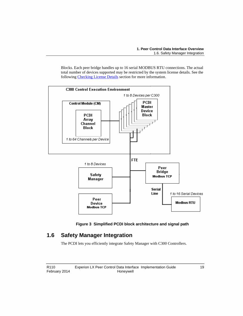
1.5 Basic Peer Control Data Interface Block Architecture As shown in the following illustration, the PCDI_MASTER block serves as the Communications Bridge between PCDI Array Request Channel blocks and Safety Manager, peer device or peer bridge with serial line MODBUS RTUs. You can configure the PCDI_MASTER block to represent a single or redundant Safety Manager, single or redundant peer (MODBUS TCP) device, or single or redundant peer (MODBUS TCP) bridge. Each PCDI_MASTER block supports up to 64 PCDI Array Request Channel
1. Peer Control Data Interface Overview 1.6. Safety Manager Integration
R110 Experion LX Peer Control Data Interface Implementation Guide 19 February 2014 Honeywell
Blocks. Each peer bridge handles up to 16 serial MODBUS RTU connections. The actual total number of devices supported may be restricted by the system license details. See the following Checking License Details section for more information.
Figure 3 Simplified PCDI block architecture and signal path
1.6 Safety Manager Integration The PCDI lets you efficiently integrate Safety Manager with C300 Controllers.

1. Peer Control Data Interface Overview 1.7. Peer Control Data Interface Processing Characteristics
20 Experion LX Peer Control Data Interface Implementation Guide R110 Honeywell February 2014
REFERENCE - INTERNAL
Refer to the Safety Manager integration Guide for more information about integrating Safety Manager with C300 Controller.
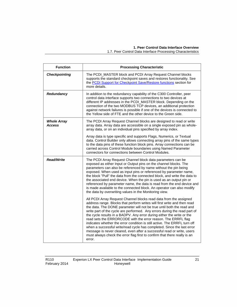
1.7 Peer Control Data Interface Processing Characteristics
The following table summarizes some peer control data interface processing characteristics for the given function.
Function Processing Characteristic
Scheduling The PCDI_MASTER block is executed for every basic cycle (50 milliseconds) prior to the execution of any Control Modules. Each PCDI_MASTER block has its own EXECSTATE. The EXECSTATE is Inactive when the block is loaded. You set the EXECSTATE to Active the same as you would a Control Module after loading.
The PCDI Array Request Channel block is executed at the execution cycle of its container Control Module. The block does not have its own EXECSTATE. The EXECSTATE of the Control Module controls the execution state of the PCDI Array Channel block.
The PCDI Array Request Channel block runs in either the triggered or auto-triggered mode. In triggered mode, the block submits a request on the positive transition of the input trigger flag. In auto-triggered mode, the DONE flag is internally looped back to the trigger to provide the fastest update rate possible. In this mode, the block is capable of refreshing data at the same rate as the execution cycle of the containing CM - limited by the response time of the addressed device
Alarming The PCDI_MASTER block serves as the notification detector for all PCDI related alarms. The alarms are classified as System Diagnostic Notification ones that map to the System Alarm category with condition name of DIAG on Experion LX Alarm Summary, System Status Display and Event Summary on Station.
The PCDI Array Request Channel blocks will report channel alarms through the PCDI_MASTER block it is attached to. If an alarm condition no longer exists or the block becomes inactive or it is deleted, channel alarms will return to normal.
1. Peer Control Data Interface Overview 1.7. Peer Control Data Interface Processing Characteristics
R110 Experion LX Peer Control Data Interface Implementation Guide 21 February 2014 Honeywell
Function Processing Characteristic
Checkpointing The PCDI_MASTER block and PCDI Array Request Channel blocks supports the standard checkpoint saves and restores functionality. See the PCDI Support for Checkpoint Save/Restore functions section for more details.
Redundancy In addition to the redundancy capability of the C300 Controller, peer control data interface supports two connections to two devices at different IP addresses in the PCDI_MASTER block. Depending on the connection of the two MODBUS TCP devices, an additional protection against network failures is possible if one of the devices is connected to the Yellow side of FTE and the other device to the Green side.
Whole Array Access
The PCDI Array Request Channel blocks are designed to read or write array data. Array data are accessible on a single exposed pin as whole-array data, or on an individual pins specified by array index.
Array data is type specific and supports Flags, Numerics, or Textual data. Control Builder only allows connecting array pins of the same types to the data pins of these function block pins. Array connections can be carried across Control Module boundaries using Named Parameter connectors for connections between Control Modules.
Read/Write The PCDI Array Request Channel block data parameters can be exposed as either Input or Output pins on the channel blocks. The parameters can also be referenced by name without the pin being exposed. When used as input pins or referenced by parameter name, the block "Pull" the data from the connected block, and write the data to the associated end device. When the pin is used as an output pin or referenced by parameter name, the data is read from the end device and is made available to the connected block. An operator can also modify the data by overwriting values in the Monitoring view.
All PCDI Array Request Channel blocks read data from the assigned address range. Blocks that perform writes will first write and then read the data. The DONE parameter will not be true until both the read and write part of the cycle are performed. Any errors during the read part of the cycle results in a BADPV. Any error during either the write or the read sets the ERRORCODE with the error reason. The ERRFL flag indicates whether the error condition is still active. The ERRFL turn off when a successful write/read cycle has completed. Since the last error message is never cleared, even after a successful read or write, users must always check the error flag first to confirm that there really is an error.
1. Peer Control Data Interface Overview 1.7. Peer Control Data Interface Processing Characteristics
22 Experion LX Peer Control Data Interface Implementation Guide R110 Honeywell February 2014
Function Processing Characteristic
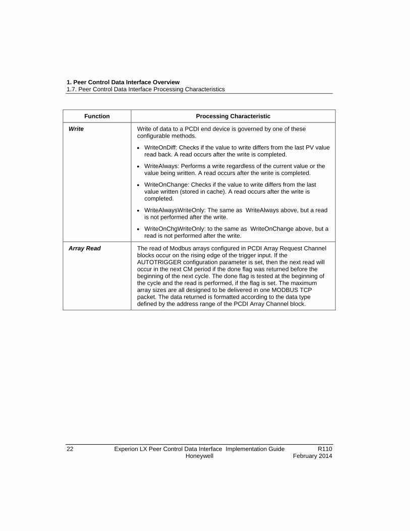
Write Write of data to a PCDI end device is governed by one of these configurable methods.
• WriteOnDiff: Checks if the value to write differs from the last PV value read back. A read occurs after the write is completed.
• WriteAlways: Performs a write regardless of the current value or the value being written. A read occurs after the write is completed.
• WriteOnChange: Checks if the value to write differs from the last value written (stored in cache). A read occurs after the write is completed.
• WriteAlwaysWriteOnly: The same as WriteAlways above, but a read is not performed after the write.
• WriteOnChgWriteOnly: to the same as WriteOnChange above, but a read is not performed after the write.
Array Read The read of Modbus arrays configured in PCDI Array Request Channel blocks occur on the rising edge of the trigger input. If the AUTOTRIGGER configuration parameter is set, then the next read will occur in the next CM period if the done flag was returned before the beginning of the next cycle. The done flag is tested at the beginning of the cycle and the read is performed, if the flag is set. The maximum array sizes are all designed to be delivered in one MODBUS TCP packet. The data returned is formatted according to the data type defined by the address range of the PCDI Array Channel block.

R110 Experion LX Peer Control Data Interface Implementation Guide 23 February 2014 Honeywell
2. Peer Control Data Interface Planning and Design
2.1 General Planning References Refer to the following publications for planning and designing details of the Experion LX system in general and the Fault Tolerant Ethernet network. For the sake of brevity, this Guide does not repeat the applicable general guidelines, considerations, cautions, and so on that are covered in these other Guides.
• Control Hardware Planning Guide
• Station Planning Guide
• Fault Tolerant Ethernet Overview and Implementation Guide
2.2 Peer Control Data Interface Requirements Ensure that your Experion LX System meets the following minimum requirements to implement peer control data interface functions.
• License for peer control data interface components.
• Experion LX Station and Control Builder.
• Non-Redundant or Redundant C300 Controller with compatible firmware.
• SIM-C300 Controller for simulation support is optional.
2.3 MODBUS System Considerations The following are some things you must consider when planning your MODBUS system for peer control data interface.
• Record the primary and secondary IP addresses for each MODBUS TCP Device.
• Map how you want to set up the MODBUS system in relation to the 64 request channels available per PCDI_MASTER block and considering that each MODBUS TCP Bridge can have a maximum of 16 MODBUS RTU devices.
2. Peer Control Data Interface Planning and Design 2.4. Write option selection considerations
24 Experion LX Peer Control Data Interface Implementation Guide R110 Honeywell February 2014
• List of MODBUS RTU devices and key properties that will be mapped to the PCDI Array Request Channel blocks.
• MODBUS RTU devices are addressed from 1 to 247 and 255. A value of 0 (zero) indicates no device is configured (removes the device). Addresses 248 to 254 are reserved.
• You can configure the PCDI_MASTER block to represent a MODBUS TCP Bridge that can support a maximum of 16 MODBUS RTU devices.
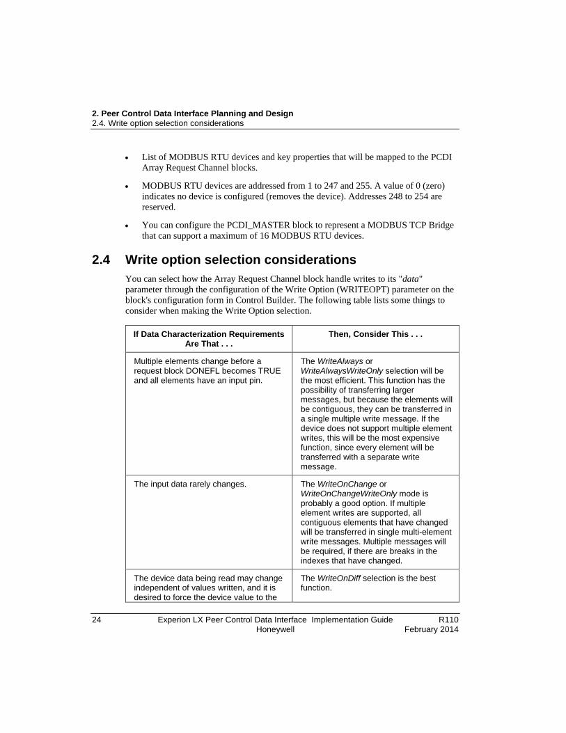
2.4 Write option selection considerations You can select how the Array Request Channel block handle writes to its "data" parameter through the configuration of the Write Option (WRITEOPT) parameter on the block's configuration form in Control Builder. The following table lists some things to consider when making the Write Option selection.
If Data Characterization Requirements
Are That . . . Then, Consider This . . .
Multiple elements change before a request block DONEFL becomes TRUE and all elements have an input pin.
The WriteAlways or WriteAlwaysWriteOnly selection will be the most efficient. This function has the possibility of transferring larger messages, but because the elements will be contiguous, they can be transferred in a single multiple write message. If the device does not support multiple element writes, this will be the most expensive function, since every element will be transferred with a separate write message.
The input data rarely changes. The WriteOnChange or WriteOnChangeWriteOnly mode is probably a good option. If multiple element writes are supported, all contiguous elements that have changed will be transferred in single multi-element write messages. Multiple messages will be required, if there are breaks in the indexes that have changed.
The device data being read may change independent of values written, and it is desired to force the device value to the
The WriteOnDiff selection is the best function.

2. Peer Control Data Interface Planning and Design 2.5. Performance Considerations
R110 Experion LX Peer Control Data Interface Implementation Guide 25 February 2014 Honeywell
If Data Characterization Requirements Are That . . .
Then, Consider This . . .
input value.
2.5 Performance Considerations The following table lists some C300 and MODBUS performance related data for general planning purposes. This information is subject to change without notice.
C300 Controller1
Number of PCDI_MASTER blocks per C300 Controller
8 maximum (One block per connected Safety Manager, peer device or peer bridge.)
Number of Serial MODBUS RTUs per C300 Controller
128 maximum (16 devices maximum per MODBUS TCP Bridge times 8 MODBUS TCP Bridges maximum per C300 Controller.)
Number of Channels per PCDI_MASTER block
64 maximum
Bytes per Second per Channel 256
Message per Second 1 (A maximum message is 256 bytes.)
Performance Estimate2 XU409688164 =∗∗∗
MODBUS3
Byte Rate 11
BaudrateByteRate =
Maximum Packet Size for Reads 256 bytes for all function codes (The request packet is 6 bytes long.)
Maximum Packet Size for Writes 256 bytes (The acknowledgement packet is 6 bytes long.)
Maximum Packet Size Rate )( 625611
Baudrate Rate Size Packet +∗=
Rate per Request Baudrate ∗ 2915 + device processing time

2. Peer Control Data Interface Planning and Design 2.6. Safety Manager Performance Considerations
26 Experion LX Peer Control Data Interface Implementation Guide R110 Honeywell February 2014
Maximum Data Delivery Takes into account a single Array Request Channel block at 50 milliseconds. The maximum rate would be 64 times this rate.
Notes: 1 The use of write on change or write on difference for arrays of flags or numerics will have an effect on C300 performance due to the number of requests that will be queued. The individual elements of the array that change will each generate a request. The calculation of the impact on the C300 execution units must include the maximum number of writes that will occur for array writes. To minimize the C300 impact, write always for arrays should be used. However, this will have a negative impact on serial MODBUS connections due to the write of data that is identical to what is already in the MODBUS device. 2 Assumes that performance will be similar to Exchange block requirement of 8 XUs (exchange units) per message per second. 3 The use of write on change or write on difference for arrays of flags or numerics will have an effect on performance due to the number of requests that will be queued. The individual elements of the array that change will each generate a request. The performance of the low speed MODBUS serial bus will be impacted by the write of a whole array where only some elements change.
2.6 Safety Manager Performance Considerations The following table lists some of the Safety Manager performance-related data for general planning purposes. This information is subject to change without notice.
Safety Manager Communications Performance
Maximum Number of parameters that can be Read from Safety Manager by C300
Unlimited PPS 1
Maximum Number of parameters that can be Written to Safety Manager from C300 (single writes exclusively)
64 per cycle 2
Maximum Number of parameters that can be Written to Safety Manager from C300 (block writes exclusively)
592 bytes per cycle 2
Bandwidth usage formulas for a mixture of single writes and block writes (time and size are the key constraints)
See equations below table
Notes: 1 Safety Manager mutli-processor architecture enables support of an unlimited number

2. Peer Control Data Interface Planning and Design 2.6. Safety Manager Performance Considerations
R110 Experion LX Peer Control Data Interface Implementation Guide 27 February 2014 Honeywell
of reads. 2 "Cycle" refers to the Safety Manager application cycle.
To avoid overruns, writes to Safety Manager must be kept within the following limits:
25250
secondper written Bytes #2
secondper messages Write#≤
+
and
( ) bytes640100 0
≤×++∑ ∑n m
SingleRblockMblock
Where:
Single = a single write command
Mblock = marker or coil block write command
Rblock = register block write command
Note that the minimum number of bytes written per message is 4.

2. Peer Control Data Interface Planning and Design 2.6. Safety Manager Performance Considerations
28 Experion LX Peer Control Data Interface Implementation Guide R110 Honeywell February 2014

R110 Experion LX Peer Control Data Interface Implementation Guide 29 February 2014 Honeywell
3. Peer Control Data Interface Installation and Upgrades
3.1 Experion LX Software Installation The Peer Control Data Interface is provided as part of the Experion LX R110 software. Refer to the Experion LX Software Installation User's Guide for details about installing the Experion LX software.
3.2 FTE Network Installation Refer to the Fault Tolerant Ethernet Installation and Service Guide for information about installing a FTE network. It is beyond the scope of this document to cover specific FTE installation details.
3.3 Hardware Installation Refer to the applicable Honeywell or vendor component documentation for details about installing any Experion LX control hardware or MODBUS TCP related hardware.
3.4 Safety Manager Software Installation The Peer Control Data Interface support is provided as part of the Safety Manager R130 software. Refer to the Safety Manager Installation and Upgrade Guide for details about installing Safety Builder software.

3. Peer Control Data Interface Installation and Upgrades 3.5. General Installation Considerations and Restrictions
30 Experion LX Peer Control Data Interface Implementation Guide R110 Honeywell February 2014
3.5 General Installation Considerations and Restrictions The following table lists some general considerations and/or restrictions related to a given installation function.
Function Consideration/Restriction
Network Connection
You may connect peer devices to Level 2 configured FTE network ports, just as you would do for Experion LX server or console. You must configure the devices for 100 megabit full duplex operation. Avoid using bridges or end devices that can only run at 10 megabits. For redundant bridges or end devices, we recommend connecting one device to the Yellow switch side and one to the Green switch side of FTE. If devices have built in network redundancy, connect one cable to Yellow and one to Green.
Be aware that the current Safety Manager (SM) is a Non-FTE node. This means that SM may demonstrate single node connection behavior in a redundant topology in response to a FTE network problem, such as a break in the crossover cable.
IP Address Assignments
Follow IP address rules for either Level 1 or Level 2, depending on where the device is connected.
Serial MODBUS RTU Connections
You must connect serial MODBUS RTU devices on a serial bus, such as RS232, RS422/RS485 full duplex, or RS485 half duplex, to the C300 MODBUS TCP subsystem through a bridge device. You must connect these devices in a daisy chain manner. A terminator may be required possibly at each end depending on the number of devices and the total length of the connecting cables.

R110 Experion LX Peer Control Data Interface Implementation Guide 31 February 2014 Honeywell
4. Peer Control Data Interface Configuration
4.1 References If you have never used Control Builder to build Experion LX control strategy, refer to the Control Building User's Guide for more information about using the application to build a control strategy.
Refer to the following documents for more details about individual parameters and function blocks.
• Control Builder Parameter Reference
• Control Builder Components Reference
• Control Builder Error Codes Reference
4.2 Adding Peer Control Data Interface Device (PCDI_MASTER) Block to Project Prerequisites
• Your Experion LX Server is running R110 software.
• You have started Configuration Studio and launched the Control Builder application.
• You have logged on with sufficient privileges to create control strategies using Control Builder.
• If applicable, you have configured the applicable IP addresses when you set up your FTE network.
Considerations • You can only view PCDI_MASTER blocks in the Project tab set for Assignment
view. The Assignment view shows the relationship among all blocks while the Containment view only shows templates that contain other templates or Control Modules (CM), Sequential Control Modules (SCM), and basic blocks. To toggle the view, right-click in an open area of the tab window and select Assignment View or Containment View from the list, as applicable.
• Each PCDI_MASTER block is automatically assigned a unique default tag name when it is created. If your system will include multiple PCDI_MASTER blocks, you may want to adopt a more structured syntax for naming them.

4. Peer Control Data Interface Configuration 4.2. Adding Peer Control Data Interface Device (PCDI_MASTER) Block to Project
32 Experion LX Peer Control Data Interface Implementation Guide R110 Honeywell February 2014
• The block tag or module name must be unique to identify the block in the system. It must contain at least one letter (A-Z) and can be up to 16 characters long. Note that most special characters (such as +, \, =, /, #, etc.) and spaces are not allowed
• The item name can be up to 40 characters long and must contain at least one letter (A-Z). It is a name by which an entity is known within the context of the enterprise model. The Item name must be unique among children of the same containment parent in the Simplified Enterprise Model Builder hierarchy and must conform to the standard convention names within the system.
• The module description text can be up to 132 characters long and appears both on detail and group displays.
• The PCDI_MASTER block icon changes appearance in Project, based on the device type it is configured to represent.
• The current Peer Control Data Interface function does not support MODBUS end device configuration.
• The Keep Alive functionality is a TCP setting that attempts to use the same socket connection for multiple requests. Keeping socket connections in use instead of releasing them after use can result in reduced network traffic.
• For redundant peer devices, the same Unit ID is applied to both the primary and secondary devices.
• The Unit ID field carries the MODBUS slave address of the remote device, when addressing a device on a MODBUS+ or MODBUS serial line sub-network through a Bridge. It identifies the slave device connected on the sub-network behind the bridge. The destination IP address identifies the bridge itself and the bridge uses the MODBUS Unit ID to forward the request to the right slave device.
• The PCDI_MASTER block initiates connection attempts and monitors device connection state. It establishes connections to the configured primary and secondary devices by setting the desired connection state and signaling the Requestor task when a connection activity is required. It monitors the status of pending requests for the Unit IDs configured for its MODBUS TCP device. The PCDI_MASTER controls retries of pending requests as well as times out the request once all retries have failed.
• The PCDI_MASTER block monitors a timestamp value for each configured MODBUS Unit ID. The timestamp is updated whenever there is a request sent for the specific unit. If the elapsed period from the last activity to the current time exceeds the LOOPRATE parameter time, the PCDI_MASTER block submits a

4. Peer Control Data Interface Configuration 4.2. Adding Peer Control Data Interface Device (PCDI_MASTER) Block to Project
R110 Experion LX Peer Control Data Interface Implementation Guide 33 February 2014 Honeywell
diagnostic request. This requires one request per serial device be allocated by the PCDI_MASTER block during initialization.
• The following table summarizes how Test Mode (LOOPMODE) and Data Change (LOOPDATACHG) parameter configuration combine to determine how data is evaluated.
If Test Mode1
(LOOPMODE) Is . . . And, Data Change2
(LOOPDATACHG) Is . . . Then, Data Evaluation . . .
ReadOnly No Change Verifies that returned data value matches the Data value specified.
Any Value Checks for a successful read but does not verify the content.
Increment or Invert For Coil or Discrete Input: Same as Any Value, since it would be impossible to synchronize reads with a changing target device value.
For Holding and Input Registers: Looks for a value different from the last read value.
Write/Read No Change Always writes the same value and expects the same value back from the read.
Any Value Only validates that a successful read occurred.
Increment Increments the value to write and then check for the result to read.
Invert Inverts the last value written and then checks for the result.
1For Type (LOOPTYPE) Diag Loopback Test Mode does not matter. It sends a 08/00 (diagnostic - return query data) command and checks the echoed result. For Types Comm Event Log, Exception Status, and Diag Register, Test Mode does not matter. They are always ReadOnly. The Comm Event Log and Exception Status Types formats the resulting data into a report string, which is displayed in the Slave Device Definitions grid, Unit ID, Data field for MODBUS RTU devices or in the Primary Data/Secondary Data fields for native devices. 2The Diag Register Type can be queried and checked using the Data Change and Data value. Safety Manager has integrated support for this feature. Test Mode, Data, and Data Change options have no affect for Safety Manager when the Type selected is Diag Register.

4. Peer Control Data Interface Configuration 4.2. Adding Peer Control Data Interface Device (PCDI_MASTER) Block to Project
34 Experion LX Peer Control Data Interface Implementation Guide R110 Honeywell February 2014
To add PCDI_MASTER block to Project
Step Action
1 On the Library tab, click the plus sign for the PCDI library to expand the tree. Drag and drop the PCDI_MASTER block icon from the library to the Project tab.
2 In the open Name New Function Block(s) dialog, you can either:
• Type a new Tag Name in its Destination box and/or a new Item Name in its Destination box and click the Finish button to close the dialog and save the name changes. Or,
• Click the Finish button to close the dialog and accept the default Tag Name and blank Item Name entries.

4. Peer Control Data Interface Configuration 4.2. Adding Peer Control Data Interface Device (PCDI_MASTER) Block to Project
R110 Experion LX Peer Control Data Interface Implementation Guide 35 February 2014 Honeywell
Step Action
3 Check if the PCDI_MASTER block icon is present in the Unassigned directory in the Project tab.
4 If you want to assign the PCDI_MASTER block to a C300 execution environment (CEEC300) now before configuring it, go to the section Assigning PCDI_Master Block to Execution Environment before continuing with next step.
5 Else, go to the next section To configure PCDI_MASTER block in Project to continue with this procedure.

4. Peer Control Data Interface Configuration 4.2. Adding Peer Control Data Interface Device (PCDI_MASTER) Block to Project
36 Experion LX Peer Control Data Interface Implementation Guide R110 Honeywell February 2014
To configure PCDI_MASTER block in Project This procedure assumes that you have completed the previous one.
Step Action
1 Right-click the named PCDI_MASTER block icon and select Module Properties from the list to call up the block's Properties form for configuration.
• You can skip Steps 2 and 3, if you have already entered the desired Module Name and Item Name for the device.
2 If you want to change the default module name, double-click the Module Name box to highlight it and type the module name. Click the cursor in the Item Name box. Otherwise, go to Step 3.
3 Place the cursor in the Item Name box, type the name of the item to which this object will be associated in the Simplified Enterprise Model Builder hierarchy.
ATTENTIONtion can clear any previously entered configuration data, as the device relate
Be aware that changing the Device Type selec d defaults are reset.
4 Click the down-arrow in the Device Type (DEVTYPE) box and select the Safety Manager or peer device from the list that the PCDI_MASTER block has to represent.
5 The Currently Assigned Channels list box is read only. It is automatically populated when a PCDI Array Request block is assigned to it.
6 • Click the Module Configuration tab to display it.
• With cursor in Primary IP Address (PRIMIP) box, key in the IP address for the primary or non-redundant device this block represents.

4. Peer Control Data Interface Configuration 4.2. Adding Peer Control Data Interface Device (PCDI_MASTER) Block to Project
R110 Experion LX Peer Control Data Interface Implementation Guide 37 February 2014 Honeywell
Step Action
7 Click the <Tab> key to move the cursor to the Primary TCP Port (PRIMTCP) box. All MODBUS/TCP application data unit (ADU) are sent through TCP to registered port 502. The default value is 502.
8 • If you have selected a single (non-redundant) device type, you can skip this step.
• Place the cursor in Secondary IP Address (SECIP) box, type the IP address of the redundant device this block represents. This address must be different than one used for the primary IP address (PRIMIP). (Only available when redundant device type is selected.)
9 • If you have selected a single (non-redundant) device type, you can skip this step.
• Click the <Tab> key to move the cursor to the Secondary TCP Port (SECTCP) box. The default value is 502. (Only available when redundant device type is selected.) An error message appears, if an invalid number, such as zero (0), is entered. A zero value cannot be stored to the database.
10 • If you have selected a single (non-redundant) device type, you can skip this step.
• Click the down-arrow button in the Connection to use (CONTOUSE) box and select the desired connection to use. The default selection is AUTO, so either the primary or secondary connection is automatically selected based upon a device failover.
TIP
In the Monitoring mode, you can use the CONTOUSE selection to force a specific connection. For example, you can select Secondary and it will be the only connection used while the primary is disconnected and disabled in this mode. This can be useful when performing maintenance on network or end-device equipment. An event is issued to indicate that an alternate connection is disabled. No other channel or device failures are reported, and active events at the time of the change become inactive.

4. Peer Control Data Interface Configuration 4.2. Adding Peer Control Data Interface Device (PCDI_MASTER) Block to Project
38 Experion LX Peer Control Data Interface Implementation Guide R110 Honeywell February 2014
Step Action
11 The Connection in use (CONINUSE) box is read only and only applies for redundant devices.
12 • If you have selected a single (non-redundant) device type, you can skip this step.
• Click the down-arrow button in the Preferred connection to use (PREFERREDCONN) box and select the preferred connection to use when the CONTOUSE parameter is set to Auto. The default selection is Primary.
13 • If you have selected a single (non-redundant) device type, you can skip this step.
• With cursor in the Connection Switch Period (sec) (REDSWITCHPERIOD) box, key in the desired switch time in seconds.
14 Select the Use Keep Alive check box to enable the option or clear the check box to disable the option. The default selection is checked or enabled.
TIP
• If Device Type setting is Single or Redundant Safety Manager, all Slave Configuration parameters are set automatically to the optimal settings.
• Users with Engineer access level or above can change the Slave Configuration parameter values, except for UNITID and supported commands, in the Monitoring mode.
15 Click the Slave Configuration tab to display it.
With cursor in Timeout (ms) (DEFTIMOUT) box, key in the required MODBUS request timeout period in milliseconds. The default is 1000 milliseconds for a native device or bridge, or 1500 milliseconds for a Safety Manager. This value is used for all serial devices unless overridden by a serial device. The DEFTIMOUT and TIMOUT values must be greater than the configured slave timeout. This ensures that a master block timeout does not occur when a single serial device is unresponsive.
4. Peer Control Data Interface Configuration 4.2. Adding Peer Control Data Interface Device (PCDI_MASTER) Block to Project
R110 Experion LX Peer Control Data Interface Implementation Guide 39 February 2014 Honeywell
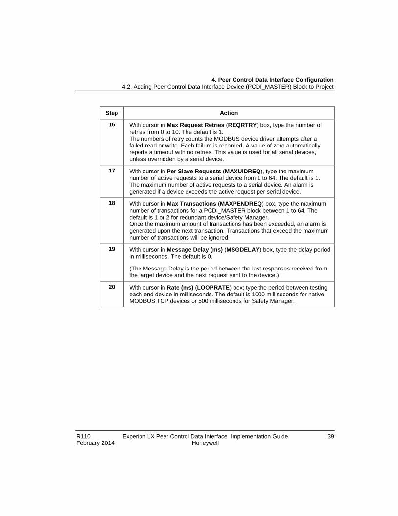
Step Action
16 With cursor in Max Request Retries (REQRTRY) box, type the number of retries from 0 to 10. The default is 1. The numbers of retry counts the MODBUS device driver attempts after a failed read or write. Each failure is recorded. A value of zero automatically reports a timeout with no retries. This value is used for all serial devices, unless overridden by a serial device.
17 With cursor in Per Slave Requests (MAXUIDREQ), type the maximum number of active requests to a serial device from 1 to 64. The default is 1. The maximum number of active requests to a serial device. An alarm is generated if a device exceeds the active request per serial device.
18 With cursor in Max Transactions (MAXPENDREQ) box, type the maximum number of transactions for a PCDI_MASTER block between 1 to 64. The default is 1 or 2 for redundant device/Safety Manager. Once the maximum amount of transactions has been exceeded, an alarm is generated upon the next transaction. Transactions that exceed the maximum number of transactions will be ignored.
19 With cursor in Message Delay (ms) (MSGDELAY) box, type the delay period in milliseconds. The default is 0.
(The Message Delay is the period between the last responses received from the target device and the next request sent to the device.)
20 With cursor in Rate (ms) (LOOPRATE) box; type the period between testing each end device in milliseconds. The default is 1000 milliseconds for native MODBUS TCP devices or 500 milliseconds for Safety Manager.

4. Peer Control Data Interface Configuration 4.2. Adding Peer Control Data Interface Device (PCDI_MASTER) Block to Project
40 Experion LX Peer Control Data Interface Implementation Guide R110 Honeywell February 2014
Step Action
21 • Click the down arrow in the Type (LOOPTYPE) box and select the function from the list. The default is Diag Loopback or Diag Register for Safety Manager.
• If your LOOPTYPE selection is Coil, Discrete Input, Holding Reg, or Input
Reg, go to Step 22.
• If your LOOPTYPE selection is Diag Loopback, go to Step 23.
• If your LOOPTYPE selection is Diag Register, go to Step 24.
• If your LOOPTYPE selection is Comm Event Log or Exception Status, go to Step 25.
22 The Address (LOOPADDR) box is read only in Monitoring mode.
(This box is only available if LOOPTYPE selection is Coil, Discrete Input, Holding Reg, or Input Reg.)
23 With cursor in Data (LOOPDATA) box, type the loop data value as TRUE, FALSE, ON, OFF, 0, or 1 for Coil or Discrete Input; or as integer or hexadecimal, with prefix "0x", format for Holding Reg or Input Reg. The default is 0xA5A5.
(This box is only available if LOOPTYPE selection is Coil, Discrete Input, Holding Reg, Input Reg, or Diag Loopback.)

4. Peer Control Data Interface Configuration 4.2. Adding Peer Control Data Interface Device (PCDI_MASTER) Block to Project
R110 Experion LX Peer Control Data Interface Implementation Guide 41 February 2014 Honeywell
Step Action
24 Click the down arrow in the Data Change (LOOPDATACHG) box and select function from the list. The default option selected is No Change.
(This box is only available if LOOPTYPE selection is Coil, Discrete Input, Holding Reg, Input Reg, Diag Loopback or .Diag Register.)
25 Click the down arrow in the Test Mode (LOOPMODE) box and select the function from the list. The default option selected is Read Only.
26 • If the selected Device Type (DEVTYPE) is single or redundant MODBUS TCP Bridge, go to Step 28.
• If the Selected Device Type (DEVTYPE) is single or redundant MODBUS TCP Device, go to Step 29.
• If the selected Device Type (DEVTYPE) is single or redundant Safety Manager, go to Step 30.
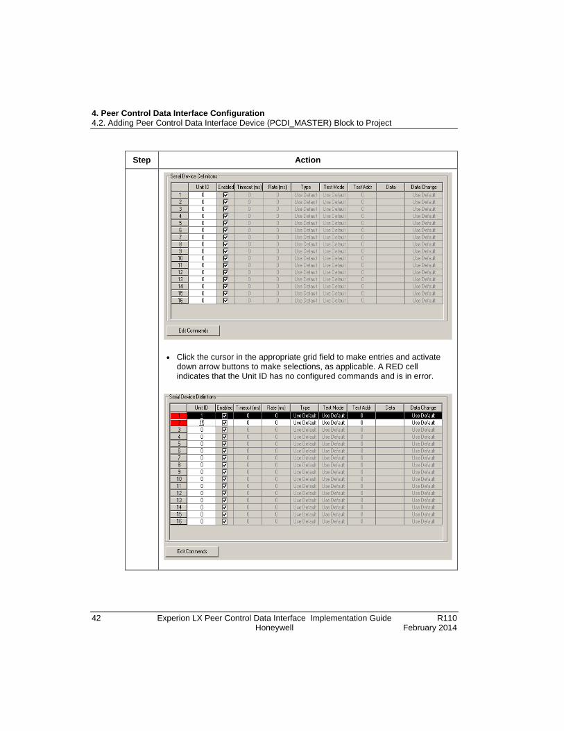
27 The Slave Configuration tab for a MODBUS TCP Bridge device type includes the Serial Device Definitions grid for configuring details about each serial device connected to the bridge.
• You must enter a valid Unit ID (1 to 247 or 255) to activate the fields in the grid for the assigned unit. A Unit ID of zero (0) is valid to remove a device, but at least one device (non-zero) must be configured.
4. Peer Control Data Interface Configuration 4.2. Adding Peer Control Data Interface Device (PCDI_MASTER) Block to Project
42 Experion LX Peer Control Data Interface Implementation Guide R110 Honeywell February 2014
Step Action
• Click the cursor in the appropriate grid field to make entries and activate
down arrow buttons to make selections, as applicable. A RED cell indicates that the Unit ID has no configured commands and is in error.

4. Peer Control Data Interface Configuration 4.2. Adding Peer Control Data Interface Device (PCDI_MASTER) Block to Project
R110 Experion LX Peer Control Data Interface Implementation Guide 43 February 2014 Honeywell
Step Action
TIP
Do not select commands that the device does not support. This prevents unsupported commands from being issued and avoids lengthy timeouts that result in decreased performance and connection reconnects. Safety Manager Commands are automatically configured.
27A • Select a given device in the grid and click the Edit Commands button to call the Configure Device dialog. Select the required commands for the selected device.
• Ensure to enter the configuration data for each device connected to the
bridge.
• Go to Step 29.
4. Peer Control Data Interface Configuration 4.2. Adding Peer Control Data Interface Device (PCDI_MASTER) Block to Project
44 Experion LX Peer Control Data Interface Implementation Guide R110 Honeywell February 2014
Step Action
27B Optional
You can enter values in the grid fields to override the default behavior of the values configured in Steps 15 to 26.
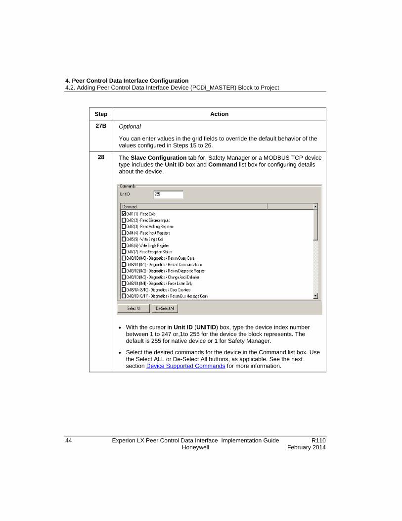
28 The Slave Configuration tab for Safety Manager or a MODBUS TCP device type includes the Unit ID box and Command list box for configuring details about the device.
• With the cursor in Unit ID (UNITID) box, type the device index number
between 1 to 247 or,1to 255 for the device the block represents. The default is 255 for native device or 1 for Safety Manager.
• Select the desired commands for the device in the Command list box. Use the Select ALL or De-Select All buttons, as applicable. See the next section Device Supported Commands for more information.

4. Peer Control Data Interface Configuration 4.3. Device Supported Commands
R110 Experion LX Peer Control Data Interface Implementation Guide 45 February 2014 Honeywell
Step Action
29 • Click the Module Statistics tab.
• Select the Alarming Enabled (ALMENBSTATE) check box to display the alarm conditions in the Alarm Summary and Journals.
• Clear the check box to disable the display of alarm conditions. The default is selected.
• The other parameters on this form are read only, except for RSTSTATS button, in the Monitoring mode that is not configurable in the Project. Error codes are displayed to assist users in tracing the cause of an error.
30 • Click the Connections Statistics tab.
• The parameters on this form are read only, except for the RSTERRCNT button, in the Monitoring mode that is not configurable in the Project.
31 • Click the Channel Status tab.
• The parameters on this form are read only, except for the CHANRSTSTATS button, in the Monitoring mode that is not configurable in the Project.
32 • Click the Server History tab.
• Use this tab to configure desired history parameters and create or edit server scripts. See the Control Building Guide and/or the online help for more information.
33 • Click the Server Displays tab.
• Use this tab to configure parameters associated with Station displays. See the Control Building Guide and/or the online help for more information.
34 • Click the Control Confirmation tab.
• Use this tab to configure parameters for control confirmation associated with the licensed Electronic Signature option. See the Control Building Guide and/or the online help for more information.
35 • Click the Identification tab.
• Use this tab to configure parameters associated with the licensed template option. See the Control Building Guide and/or the online help for more information.
36 When you finish entering the configuration data, click the OK button to close the configuration form and save the data.

4. Peer Control Data Interface Configuration 4.3. Device Supported Commands
46 Experion LX Peer Control Data Interface Implementation Guide R110 Honeywell February 2014
Step Action
37 This completes the procedure To configure the PCDI_MASTER block in Project.
4.3 Device Supported Commands The following table lists the supported commands by function code along with a description and PCDI block usage as well as default settings for Safety Manager.
Table 1 Device Supported Commands
Function Code
Description Used by PCDI Blocks Safety Manager Default
0x01 Read Coils PCDI_MASTER - Diag, PCDIFLAGARRCH
On
0x02 Read Discrete Inputs PCDI_MASTER - Diag, PCDIFLAGARRCH
On
0x03 Read Holding Registers PCDI_MASTER - Diag, PCDITEXTARRCH, PCDINUMARRCH
On
0x04 Read Input Registers PCDI_MASTER - Diag, PCDITEXTARRCH, PCDINUMARRCH
On
0x05 Write Single Coil PCDI_MASTER - Diag, PCDIFLAGARRCH
On
0x06 Write Single Register PCDI_MASTER - Diag, PCDITEXTARRCH, PCDINUMARRCH
On
0x07 Read Exception Status PCDI_MASTER - Diag Off
0x08 / 0x00 Diagnostic - Return Query Data
PCDI_MASTER - Diag, PCDITEXTARRCH - loopback
On
0x08 / 0x01 Diagnostic - Restart Communications
Off
0x08 / 0x02 Diagnostic - Return Diagnostic Register
PCDI_MASTER - Diag On

4. Peer Control Data Interface Configuration 4.3. Device Supported Commands
R110 Experion LX Peer Control Data Interface Implementation Guide 47 February 2014 Honeywell
Function Code
Description Used by PCDI Blocks Safety Manager Default
0x08 / 0x03 Diagnostic - Change ASCII Delimiter
Off
0x08 / 0x04 Diagnostic - Force Listen Only Off
0x08 / 0x0A Diagnostic - Clear Counters and Diagnostic Register
Off
0x08 / 0x0B Diagnostic - Return Bus Message Count
Off
0x08 / 0x0C Diagnostic - Return Bus Communication Error Count
Off
0x08 / 0x0D Diagnostic - Return Bus Exception Error Count
Off
0x08 / 0x0E Diagnostic - Return Slave Message Count
Off
0x08 / 0x0F Return Slave No Response Count
Off
0x08 / 0x10 Return Slave NAK Count Off
0x08 / 0x11 Return Slave Busy Count Off
0x08 / 0x12 Return Bus Character Overrun Count
Off
0x08 / 0x13 Return IOP Message Overrun Count
Off
0x08 / 0x14 Get / Clear MODBUS Plus stats
Off
0x0B Get Communication Event Counter
Off
0x0C Get Communication Event Log
PCDI_MASTER - Diag Off
0x0F Write Multiple Coils PCDIFLAGARRCH On
0x10 Write Multiple Registers PCDITEXTARRCH, On

4. Peer Control Data Interface Configuration 4.4. Assigning PCDI_Master Block to Execution Environment
48 Experion LX Peer Control Data Interface Implementation Guide R110 Honeywell February 2014
Function Code
Description Used by PCDI Blocks Safety Manager Default
PCDINUMARRCH
0x11 Report Slave ID Off
0x14 / 0x06 Read File Record Off
0x15 / 0x06 Write File Record Off
0x16 Mask Write Register Off
0x17 Read / Write Multiple Registers
Off
0x18 Read FIFO Queue Off
0x2B / 0x0E Read Device Information PCDI_MASTER - Vendor Info On
4.4 Assigning PCDI_Master Block to Execution Environment Prerequisites
• You have started Configuration Studio and launched the Control Builder application.
• You have logged on with sufficient privileges to create control strategies using Control Builder.
• You have created a C300 Controller block in the Project tab.
• You have added a PCDI_MASTER block to the Project tab.
Considerations • All illustrations used in the following procedure are for example purposes only.
• You can drag and drop the PCDI_MASTER block into the required CEEC300 folder in the Project tree instead of using the Execution Environment Assignment dialog box, as outlined in the following procedure.
To assign PCDI_MASTER block to CEE
Step Action

4. Peer Control Data Interface Configuration 4.4. Assigning PCDI_Master Block to Execution Environment
R110 Experion LX Peer Control Data Interface Implementation Guide 49 February 2014 Honeywell
Step Action
1 On the Edit menu, click Execution Environment Assignment; or click the
Execution Environment Assignment button on the toolbar.
The Execution Environment Assignment dialog box appears.
2 Click IOMs tab in the Available modules to display the modules.
Click the PCDI_MASTER block that needs to be assigned..
3 In the Assign To list box, click the CEE block to which the PCDI_MASTER block will be assigned..
4 Click the Assign -> button to assign the selected module to the selected CEE block.
4. Peer Control Data Interface Configuration 4.5. Adding PCDI Array Request Channel Block to Control Module
50 Experion LX Peer Control Data Interface Implementation Guide R110 Honeywell February 2014
Step Action
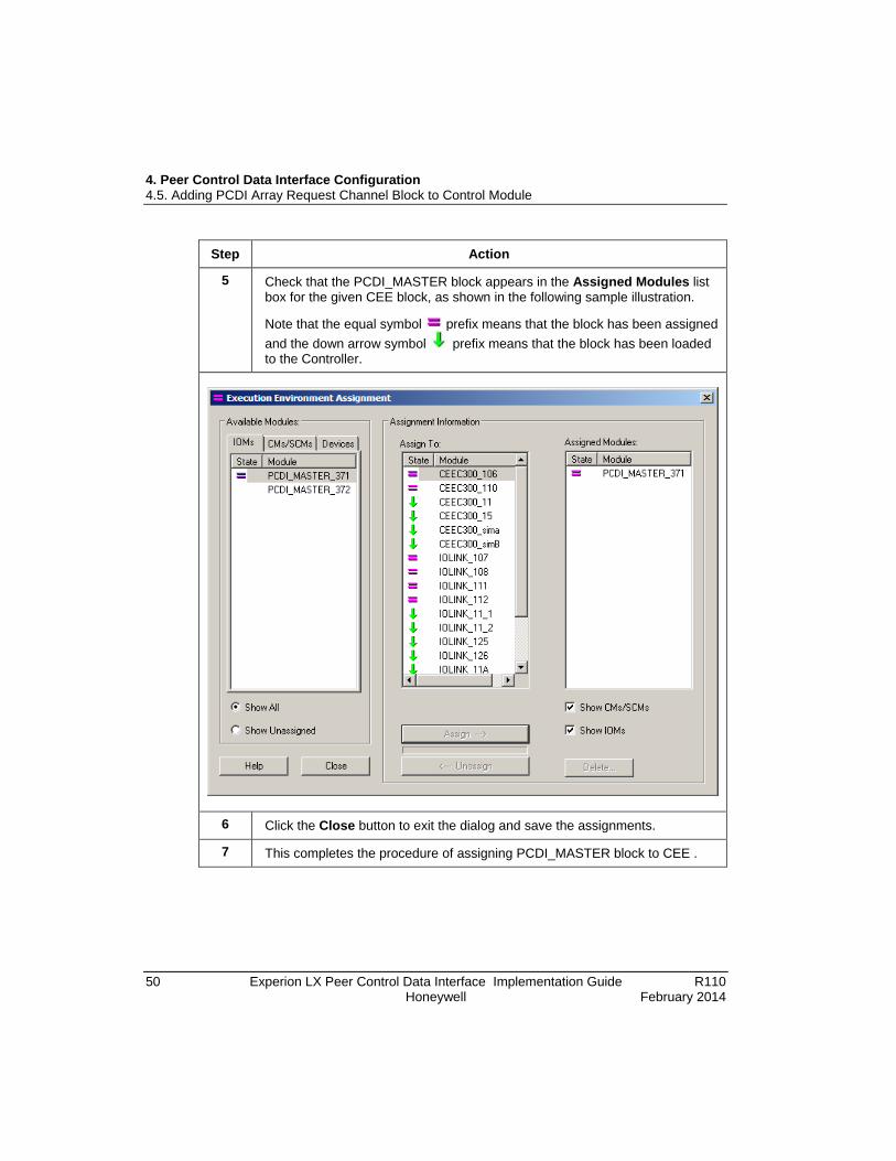
5 Check that the PCDI_MASTER block appears in the Assigned Modules list box for the given CEE block, as shown in the following sample illustration.
Note that the equal symbol prefix means that the block has been assigned and the down arrow symbol prefix means that the block has been loaded to the Controller.
6 Click the Close button to exit the dialog and save the assignments.
7 This completes the procedure of assigning PCDI_MASTER block to CEE .

4. Peer Control Data Interface Configuration 4.5. Adding PCDI Array Request Channel Block to Control Module
R110 Experion LX Peer Control Data Interface Implementation Guide 51 February 2014 Honeywell
4.5 Adding PCDI Array Request Channel Block to Control Module Prerequisites
• You have started Configuration Studio and launched the Control Builder application.
• You have logged on with sufficient privileges to create control strategies using Control Builder.
• You have added a PCDI_MASTER block to the Project tab and assigned it to a C300 Control Execution Environment.
• You have created a Control Module in the Project tab and assigned it to the same C300 Control Execution Environment as the PCDI_MASTER block.
Considerations • The following procedure adds a PCDI Numeric Array Request Channel
(PCDINUMARRCH) block to a CM and assigns a channel to a PCDI_MASTER block for example purposes only. You can easily adapt this procedure to apply to a PCDI Flag Array Request Channel (PCDIFLAGARRCH) block or a PCDI Text Array Request Channel (PCDITEXTARRCH) block.
• Each PCDI Array Request Channel block is automatically assigned a default tag name when it is created, which must only be unique within the containing Control Module. If your system includes multiple Array Channel blocks, you may want to adopt a more structured syntax for naming them.
• The request block channel name can be up to 15 characters long and must contain at least on letter (A-Z). It must not contain an embedded space or leading space, and dots are allowed in parameter naming only.
• You must either use the WriteAlwaysWriteOnly or WriteOnChgWriteOnly Write Option (WRITEOPT) selection when configuring communications for a Safety Manager device. This avoids the possibility of wrong values being sent back as a result of a read carried out directly after a write.
• The Array Request Channel blocks are designed to read or write array data. Array data are accessible on a single exposed pin as whole array data, or on individual pins specified by array index, which is configurable through the Block Pins tab on the Array Request Channel block configuration form. A sample block pin configuration is shown in the following illustration.

4. Peer Control Data Interface Configuration 4.5. Adding PCDI Array Request Channel Block to Control Module
52 Experion LX Peer Control Data Interface Implementation Guide R110 Honeywell February 2014
Figure 4 Sample Block Pin Configuration for Whole Array Access.

4. Peer Control Data Interface Configuration 4.5. Adding PCDI Array Request Channel Block to Control Module
R110 Experion LX Peer Control Data Interface Implementation Guide 53 February 2014 Honeywell
• You are responsible for verifying that the correct MODBUS addresses are maintained between request and device blocks. There is no design time validation to verify the following:
− The PCDI_MASTER Block device identifiers are synchronized with the Array Request Channel block device identifiers.
− The valid addresses are provided for devices.
• For PCDI_MASTER block to appear in the drop-down list on the Array Channel block's configuration form, the Control Module containing the Array Channel block must be assigned to the same CEE as the PCDI_MASTER block or both be unassigned in the Project.
• All illustrations used in the following procedure are for example purposes only.
To add MODBUS TCP array request channel block to CM
Step Action
1 In the Project tab, double-click Control Module icon to include an array request channel block, to open it in the Control Drawing pane, as shown in the following sample illustration.

4. Peer Control Data Interface Configuration 4.5. Adding PCDI Array Request Channel Block to Control Module
54 Experion LX Peer Control Data Interface Implementation Guide R110 Honeywell February 2014
Step Action
2 In the Library tab, select and expand the PCDI icon tree.
You can also select the tag name in the following ways.
• Select Library mode and type the initial characters of the tag name.
• Using the Search Option toolbar:
a) Type the initial few characters of the tag name in the Search Option toolbar. A list of all matching tag names appears.
b) Select the tag name and click .
If the tag exists, the tree expands and the specified tag name is highlighted.
For more information on searching the tags, see Control Building User's Guide.

4. Peer Control Data Interface Configuration 4.5. Adding PCDI Array Request Channel Block to Control Module
R110 Experion LX Peer Control Data Interface Implementation Guide 55 February 2014 Honeywell
Step Action
3 Click and drag the PCDINUMARRCH icon block to the open CM in the Control Drawing to add the block to the CM, as shown in the following sample illustration.
4. Peer Control Data Interface Configuration 4.5. Adding PCDI Array Request Channel Block to Control Module
56 Experion LX Peer Control Data Interface Implementation Guide R110 Honeywell February 2014
Step Action
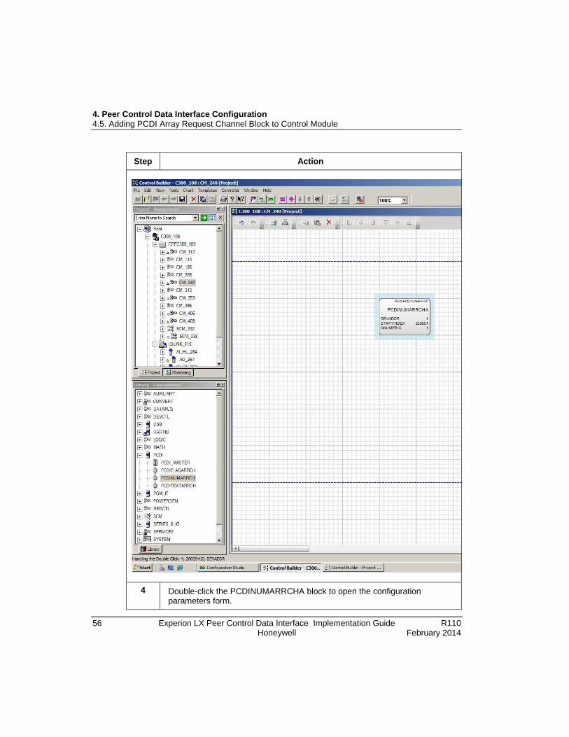
4 Double-click the PCDINUMARRCHA block to open the configuration parameters form.

4. Peer Control Data Interface Configuration 4.5. Adding PCDI Array Request Channel Block to Control Module
R110 Experion LX Peer Control Data Interface Implementation Guide 57 February 2014 Honeywell
Step Action
5 Accept the highlighted default Channel Name or key in a type a new one.
6 Double-click the Execution Order in CM box and type the number in multiples of 10 to define the execution order of the block in the CM.
4. Peer Control Data Interface Configuration 4.5. Adding PCDI Array Request Channel Block to Control Module
58 Experion LX Peer Control Data Interface Implementation Guide R110 Honeywell February 2014
Step Action
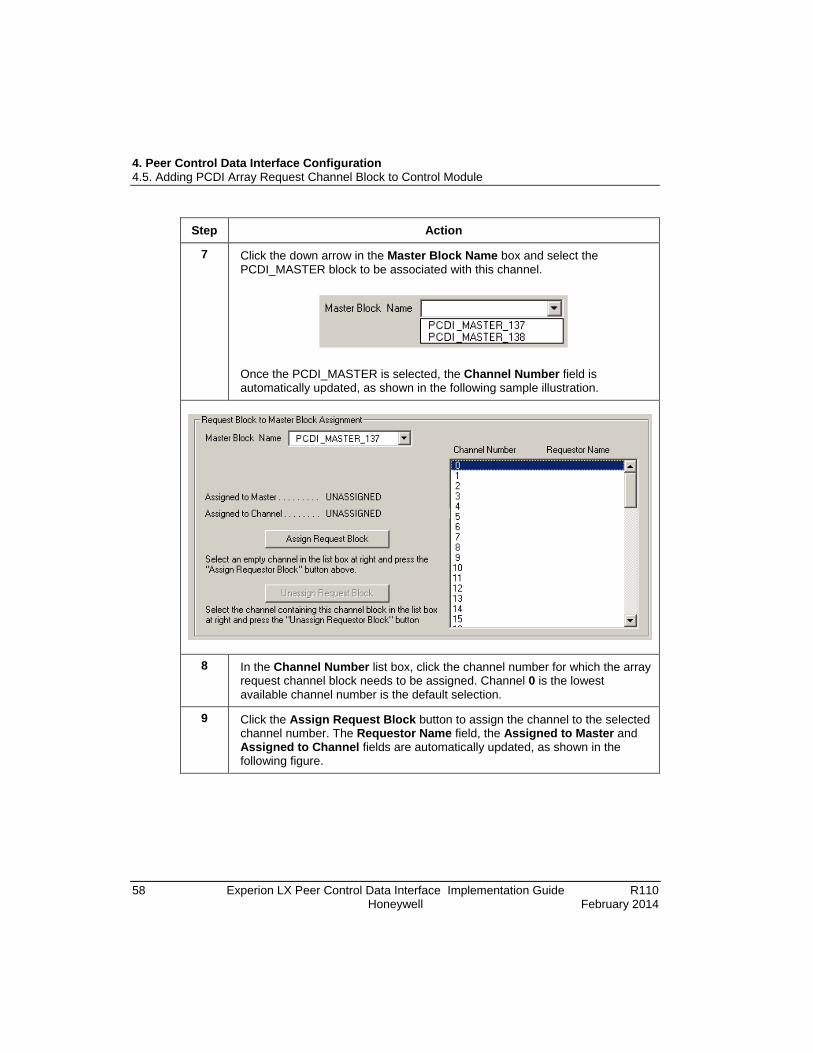
7 Click the down arrow in the Master Block Name box and select the PCDI_MASTER block to be associated with this channel.
Once the PCDI_MASTER is selected, the Channel Number field is automatically updated, as shown in the following sample illustration.
8 In the Channel Number list box, click the channel number for which the array request channel block needs to be assigned. Channel 0 is the lowest available channel number is the default selection.
9 Click the Assign Request Block button to assign the channel to the selected channel number. The Requestor Name field, the Assigned to Master and Assigned to Channel fields are automatically updated, as shown in the following figure.
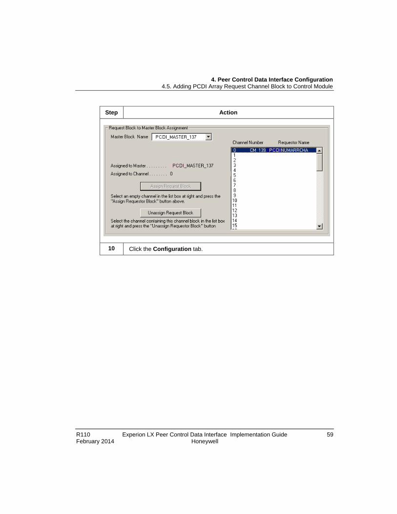
4. Peer Control Data Interface Configuration 4.5. Adding PCDI Array Request Channel Block to Control Module
R110 Experion LX Peer Control Data Interface Implementation Guide 59 February 2014 Honeywell
Step Action
10 Click the Configuration tab.

4. Peer Control Data Interface Configuration 4.5. Adding PCDI Array Request Channel Block to Control Module
60 Experion LX Peer Control Data Interface Implementation Guide R110 Honeywell February 2014
Step Action

4. Peer Control Data Interface Configuration 4.5. Adding PCDI Array Request Channel Block to Control Module
R110 Experion LX Peer Control Data Interface Implementation Guide 61 February 2014 Honeywell
Step Action
11 Click the down arrow in the Access Lock (ACCLOCK) box and select who can change the block's value or state based on signon privileges. The default is Operator. Press the Tab key to move the cursor to the Module Device Address box.
12 Select the Auto Trigger Mode (AUTOTRIGGER) check box to enable it. Clear the check box to disable it.
The default option is selected, so that the block operates in the auto-triggered mode rather than the triggered mode.
Press the Tab key to move the cursor to the Auto Trigger Period (ms) (AUTOTRIGGERPERIOD) box.
13 Type the time in milliseconds to delay the beginning of the following auto-triggered block execution. The default value is 0 milliseconds, which results in the block being triggered as quickly as possible.
Press the Tab key to move the cursor to the Device Address (DEVADDR) box.
(Auto triggered execution will resume in the Control Module cycle following expiration of the auto trigger period. If the auto trigger period has expired before the DONEFL parameter transitions to true, the block will be auto triggered immediately.)
14 Type the address that identifies the MODBUS device connected to this request channel. The default is 1.
Press the Tab key to move the cursor to the Starting Element Index (STARTINDEX) box.

4. Peer Control Data Interface Configuration 4.5. Adding PCDI Array Request Channel Block to Control Module
62 Experion LX Peer Control Data Interface Implementation Guide R110 Honeywell February 2014
Step Action
15 Type the value to identify the start of the contiguous array in the MODBUS device. See the Starting Element Index Values section for more information about configuring the start index value. Following are the default value that can vary for the given request channel type:
• PCDIFLAGARRCH = 1
• PCDINUMARRCH = 20001
• PCDITEXTARRCH = 500001
16A For PCDINUMARRCH block only:
Select the LONG (CONVTOLONG) check box to represent numeric values as longs. The default value is cleared so that numerics values are represented as floating point values.
(Checking the Long check box, provides support for 32-bit signed or unsigned integers depending on the start index specified. The Long check box has no impact on floating point numerics, which are always 32-bit. See the Startindex range 900001 - 965535 in Table 2 for more information. )
16B For PCDIFLAGARRCH block only:
Place the cursor in Number of Flag Values (NFLAG) box, type the number of Boolean values in the array of data from the device. The default is 1.
16C For PCDITEXTARRCH block only:
Select the ASCII Conversion (CONVTOASCII) checkbox to use ASCII characters. Clear the check box to use Unicode characters. The default is selected to use ASCII characters.
17A For PCDINUMARRCH block only:
With cursor in the Number of Numeric Values (NNUMERIC) box, type the number that represents the number of numeric values in the array of data from the device. The default is 1.
17B For PCDITEXTARRCH block only:
Place the cursor in the Number of String Values (NSTRING) box, type the number that represents the number of string values in the array of data from the device. The default is 1.

4. Peer Control Data Interface Configuration 4.5. Adding PCDI Array Request Channel Block to Control Module
R110 Experion LX Peer Control Data Interface Implementation Guide 63 February 2014 Honeywell
Step Action
18 For PCDITEXTARRCH block only:
Place the cursor in Char Length of String Values (STRLEN) box, key in the number of characters per string value. The default is 8.
19 Click the down arrow in the Write Option (WRITEOPT) box and select how the Array Request Channel block handles the writes to its "data" parameter. The default is WriteOnDiff.
20 a) Click the Scaling/Substitution tab to display the dialog. (This tab is titled just Substitution for PCDIFLAGARRCH and PCDITEXTARRCH blocks.)
b) Click the down arrow in the Default Substitution Type (SUBVALTYPE) box and select the value to substitute when an error occurs. The default is Last known good.
(The NaN selection is only available for PCDINUMARRCH blocks.)
21A For PCDINUMARRCH and PCDITEXTARRCH blocks only:
Place the cursor in Default Substitution Value (SUBVAL) box, type the value to substitute when an error occurs and the SUBVALTYPE setting is SUBVAL Param.
21B For PCDIFLAGARRCH block only:
Select the Set to ON on error (SUBVAL) check box to turn the flag ON when an error occurs. Leave the check box blank to disable the function. The default is cleared or disabled.
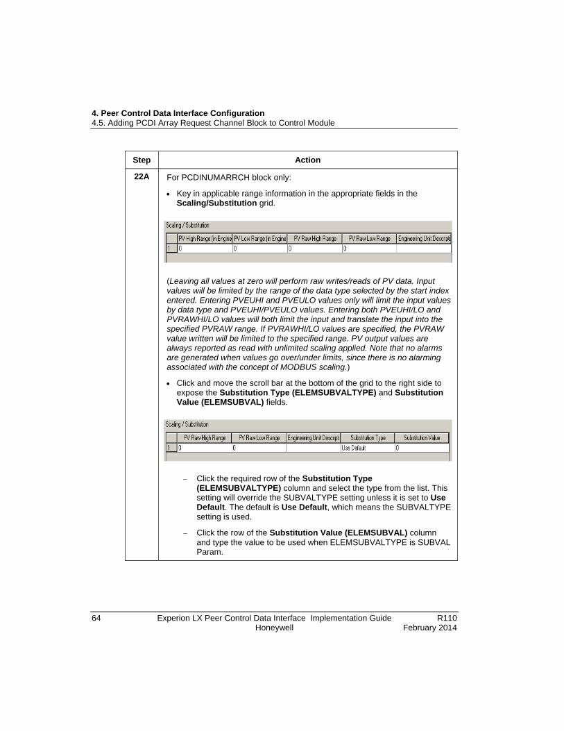
4. Peer Control Data Interface Configuration 4.5. Adding PCDI Array Request Channel Block to Control Module
64 Experion LX Peer Control Data Interface Implementation Guide R110 Honeywell February 2014
Step Action
22A For PCDINUMARRCH block only:
• Key in applicable range information in the appropriate fields in the Scaling/Substitution grid.
(Leaving all values at zero will perform raw writes/reads of PV data. Input values will be limited by the range of the data type selected by the start index entered. Entering PVEUHI and PVEULO values only will limit the input values by data type and PVEUHI/PVEULO values. Entering both PVEUHI/LO and PVRAWHI/LO values will both limit the input and translate the input into the specified PVRAW range. If PVRAWHI/LO values are specified, the PVRAW value written will be limited to the specified range. PV output values are always reported as read with unlimited scaling applied. Note that no alarms are generated when values go over/under limits, since there is no alarming associated with the concept of MODBUS scaling.)
• Click and move the scroll bar at the bottom of the grid to the right side to expose the Substitution Type (ELEMSUBVALTYPE) and Substitution Value (ELEMSUBVAL) fields.
− Click the required row of the Substitution Type (ELEMSUBVALTYPE) column and select the type from the list. This setting will override the SUBVALTYPE setting unless it is set to Use Default. The default is Use Default, which means the SUBVALTYPE setting is used.
− Click the row of the Substitution Value (ELEMSUBVAL) column and type the value to be used when ELEMSUBVALTYPE is SUBVAL Param.
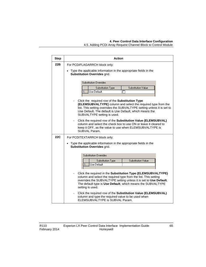
4. Peer Control Data Interface Configuration 4.5. Adding PCDI Array Request Channel Block to Control Module
R110 Experion LX Peer Control Data Interface Implementation Guide 65 February 2014 Honeywell
Step Action
22B For PCDIFLAGARRCH block only:
• Type the applicable information in the appropriate fields in the Substitution Overrides grid.
− Click the required row of the Substitution Type (ELEMSUBVALTYPE) column and select the required type from the list. This setting overrides the SUBVALTYPE setting unless it is set to Use Default. The default is Use Default, which means the SUBVALTYPE setting is used.
− Click the required row of the Substitution Value (ELEMSUBVAL) column and select the check box to use ON or leave it cleared to keep it OFF, as the value to use when ELEMSUBVALTYPE is SUBVAL Param.
22C For PCDITEXTARRCH block only:
• Type the applicable information in the appropriate fields in the Substitution Overrides grid.
− Click the required in the Substitution Type (ELEMSUBVALTYPE) column and select the required type from the list. This setting overrides the SUBVALTYPE setting unless it is set to Use Default. The default type is Use Default, which means the SUBVALTYPE setting is used.
− Click the required row of the Substitution Value (ELEMSUBVAL) column and type the required value to be used when ELEMSUBVALTYPE is SUBVAL Param.
4. Peer Control Data Interface Configuration 4.6. Starting Element Index Values
66 Experion LX Peer Control Data Interface Implementation Guide R110 Honeywell February 2014
Step Action
23 • Click the Status/Data tab.
• There are no parameters on this tab to configure in Project. Use this tab to monitor selected data in the Monitoring mode. The PCDI_MASTER block and Control Module must be loaded and active to make data available on this tab.
24 • Click the Identification tab.
• Use this tab to configure parameters associated with the licensed template option. See the Control Building Guide and/or the online help for more information.
25 • Click the Block Pins tab.
• Use this tab to configure the pins you want to expose for this block. See the Control Building Guide and/or the online help for more information.
26 • Click the Configuration Parameters tab.
• Use this tab to configure the parameters to be displayed on the block in the Project mode. See the Control Building Guide and/or the online help for more information.
27 • Click the Monitoring Parameters tab.
• Use this tab to configure the parameters to be displayed on the block in the Monitoring mode. See the Control Building Guide and/or the online help for more information.
28 • Click the Block Preferences tab.
• Use this tab to configure the viewing preferences for the block. See the Control Building Guide and/or the online help for more information.
29 • Click the Template Defining tab, if you have a template license..
• Use this tab to select the parameters that needs to be defined in the template. See the Control Building Guide and/or the online help for more information.
30 After you complete entering the configuration data, click the OK button to close the configuration form and save the data.
31 This completes the procedure to add MODBUS TCP array request channel block to CM.

4. Peer Control Data Interface Configuration 4.6. Starting Element Index Values
R110 Experion LX Peer Control Data Interface Implementation Guide 67 February 2014 Honeywell
4.6 Starting Element Index Values You can specify the Starting Element Index (STARTINDEX) parameter through the Configuration tab in the configuration form for the given PCDI Array Request Channel block in Control Builder, as explained in section To add MODBUS TCP array request channel block to CM. This parameter defines the MODBUS address map.
The value configured for the STARTINDEX parameter in a given Array Request Channel block determines the MODBUS Start Index and function. Only one type of external data can be accessed per Array Channel block.
The STARTINDEX parameter specifies the MODBUS data type and a MODBUS address up to 65535. The most significant digit identifies the MODBUS function. For example, read coil status as mentioned in the following table. The lower five digits define the starting address to access data for the given MODBUS function. For example, the address ranges 2xxxxx, 4xxxxx, 5xxxxx, 7xxxxx, 8xxxxx, and 9xxxxx all address the same xxxxx holding registers in the MODBUS end device, but with different data formats. When multiple numeric data types are used, you must configure the STARTINDEX for each array to avoid overlapping arrays.
The following table shows the relationship between MODBUS functions, the STARTINDEX parameter range, and number of elements. The maximum number of elements specifies the maximum number of flags, numerics, or strings that can be configured for a given STARTINDEX range and Array Request Channel block type. All specified elements are read in a single transaction.
Table 2 Start index ranges define MODBUS function STARTINDEX
Ranges MODBUS Function
Read FC Write FC
Array Request Channel Block
Data Range Max. No.
Elem.
000001 - 065535
Read Coil Status 01 PCDIFLAGARRCH Read/Write Bit Flags
ON/OFF 1968
Write Single Coil 05
Write Multiple Coils 15
100001 - 165535
Read Input Status 02 PCDIFLAGARRCH Read Only Bit Flags
ON/OFF 1968
Not Applicable N/A
200001 - 265535
Read Holding Registers
03 PCDINUMARRCH Word Swapped IEEE FI.Pt
Read/Write
-34E38 to 34E38
60
Write Single Register
06

4. Peer Control Data Interface Configuration 4.6. Starting Element Index Values
68 Experion LX Peer Control Data Interface Implementation Guide R110 Honeywell February 2014
STARTINDEX Ranges
MODBUS Function
Read FC Write FC
Array Request Channel Block
Data Range Max. No.
Elem.
Write Multiple Registers
16
300001 - 365535
Read Input Registers
04 PCDINUMARRCH Signed Integer Words
Read only
-32768 to 32767
120
Not Applicable N/A -2147483648 to 2147483647
60
400001 - 465535
Read Holding Registers
03 PCDINUMARRCH Signed Integer Word/Long Array
Read/Write
-32768 to 32767
120
Write Single Register
06 -2147483648 to 2147483647
60
Write Multiple Registers
16
500001 - 565535
Read Holding Registers
03 PCDITEXTARRCH ASCII Encoded Bytes or UNICODE (2 Byte) Characters
Read/Write
Printable Characters
See Note 1
Write Single Register
06
Write Multiple Registers
16
600000 Loopback Diagnostics
08 PCDITEXTARRCH Loopback Test
Printable Characters
See Note 1
600001 -665535
Read/Write Vendor Information
03/06/16 Vendor Information Transfer to Master Block
80 chars.
699999 Write Vendor Information
06/16
700001 - 765535
Read Holding Registers
03 PCDINUMARRCH IEEE Floating Point
Read/Write
-34E38 to 34E38
60
Write Single Registers
06
Write Multiple Registers
16
800002 - 865535
Read Holding Registers
03 PCDINUMARRCH IEEE FI. Pt
-34E38 to 34E38
60
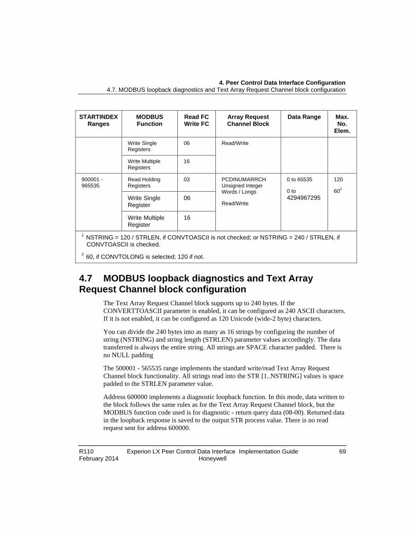
4. Peer Control Data Interface Configuration 4.7. MODBUS loopback diagnostics and Text Array Request Channel block configuration
R110 Experion LX Peer Control Data Interface Implementation Guide 69 February 2014 Honeywell
STARTINDEX Ranges
MODBUS Function
Read FC Write FC
Array Request Channel Block
Data Range Max. No.
Elem.
Write Single Registers
06 Read/Write
Write Multiple Registers
16
900001 - 965535
Read Holding Registers
03 PCDINUMARRCH Unsigned Integer Words / Longs
Read/Write
0 to 65535
0 to 4294967295
120
602 Write Single Register
06
Write Multiple Register
16
1 NSTRING = 120 / STRLEN, if CONVTOASCII is not checked; or NSTRING = 240 / STRLEN, if CONVTOASCII is checked. 2 60, if CONVTOLONG is selected; 120 if not.
4.7 MODBUS loopback diagnostics and Text Array Request Channel block configuration
The Text Array Request Channel block supports up to 240 bytes. If the CONVERTTOASCII parameter is enabled, it can be configured as 240 ASCII characters. If it is not enabled, it can be configured as 120 Unicode (wide-2 byte) characters.
You can divide the 240 bytes into as many as 16 strings by configuring the number of string (NSTRING) and string length (STRLEN) parameter values accordingly. The data transferred is always the entire string. All strings are SPACE character padded. There is no NULL padding
The 500001 - 565535 range implements the standard write/read Text Array Request Channel block functionality. All strings read into the STR [1..NSTRING] values is space padded to the STRLEN parameter value.
Address 600000 implements a diagnostic loopback function. In this mode, data written to the block follows the same rules as for the Text Array Request Channel block, but the MODBUS function code used is for diagnostic - return query data (08-00). Returned data in the loopback response is saved to the output STR process value. There is no read request sent for address 600000.

4. Peer Control Data Interface Configuration 4.8. Whole array support
70 Experion LX Peer Control Data Interface Implementation Guide R110 Honeywell February 2014
Since the MODBUS function can only handle a single word (2 bytes) at a time, the number of writes required to complete the cycle will be depend on whether CONVERTTOASCII is enabled or not, the NSTRING value, and the STRLEN value.
For Addresses in the 600001 - 665535 range, values will be transferred to both the STR process value and will be written to the associated PCDI_MASTER block VENDOR string. The VENDOR string is 80 characters and will truncate excessively long strings. If multiple strings are configured (NSTRING > 1), the strings read will be concatenated with a SPACE character separating them. Only printable characters will be transferred to the VENDOR string.
Address 699999 provides a means of transferring input data on the STR[1..NSTRING] input pins into the PCDI_MASTER block VENDOR string. The same rules apply for the transfer of data as for the previous address range.
4.8 Whole array support A whole array transfer allows you to connect together two arrayed parameters in Control Builder with the same data type. Once the configuration is loaded and running, the connection is formed between the two parameters and the entire array is requested and transferred to the destination block as one parameter access request. The array is available as a named parameter for connection to peer controllers by connecting to the parameter name.
Array write scenario With whole array transfer, the write data can be brought in as an array from another block that supports whole array transfer. A whole array write can occur, if the write method is set to WriteAlways. With the other methods, the data write will be one element at a time.
The WriteAlways function will write all values transferred into the block. The WriteOnDiff and WriteOnChg functions will optimize use of single and multiple write commands to minimize the number of Control Module (CM) cycles required to transfer only those values that are different or changed. Use of single or multiple write commands is restricted by the commands selected in the Supported Commands dialog through the PCDI_MASTER block configuration form.
4.9 Simulation support When you assign a PCDI_MASTER block and CM containing associated PCDI Array Request Channel blocks to the CEESIMC300FB, the blocks support the SIM-C300 simulation environment such that their input values can be read and written to by an operator or other applications. You can run the simulation of Array Request Channel
4. Peer Control Data Interface Configuration 4.10. Loading configuration data to the CEE
R110 Experion LX Peer Control Data Interface Implementation Guide 71 February 2014 Honeywell
blocks with or without a PCDI_MASTER block. For simulations without a PCDI_MASTER block, the alarms are not supported.
In the simulation environment, the communication between PCDI_MASTER block and MODBUS TCP hardware is blocked. You generate alarms manually by setting connection status, ERRFL, device status, and so on. The channel state for PCDI Array Request Channel blocks is put in simulate and is displayed on the channel block faceplate in Station and on the Channel Status tab of PCDI_MASTER block configuration form in the Monitoring tab of Control Builder.
You can configure the simulation mode as DirectSub, SimValueSub, or None. When mode is DirectSub, an operator or other application can write directly to the PV, ignoring the connection. When mode is SimValueSub, the SIMVALUE is substituted for the PV. The SIMVALUE can be fetched from another block using a parameter connection or it can be set by an operator or the other applications. In both modes, Error Flag and Error Code can be written by an operator or the other applications. When mode is None, the PV is fetched from connected blocks, or from applications or users with proper access level.
4.10 Loading configuration data to the CEE Prerequisites
• You have started Configuration Studio and launched the Control Builder application.
• You have logged on with sufficient privileges to create control strategies using Control Builder.
• You have loaded the Controller and its execution environment.
• You have assigned the PCDI_MASTER block to the loaded Execution Environment
Considerations • The following procedure is based on doing an initial load of a block from the
Project tab. You can also initiate a re-load of a block from the Monitoring tab.
• You can load the CEE and its assigned contents such as I/O modules and Control Modules at the same time. See the Control Building User's Guide for more information about the load operation.
• The PCDI Array Request Channel blocks are loaded with their containing Control Module.
• All the illustrations used in the procedure are for example purposes only.
4. Peer Control Data Interface Configuration 4.10. Loading configuration data to the CEE
72 Experion LX Peer Control Data Interface Implementation Guide R110 Honeywell February 2014
The load operation is still an offline function. The Load Dialog box provides the ability to automatically inactivate a component during a load and then return the component to its active state. Do not use this automatic inactivate/activate function, if your process cannot tolerate the load disruption and consequent delay in activation. In this case, you must manually toggle the component state through the Monitoring tab in Control Builder.
To load PCDI_MASTER block
Step Action
1 In the Project tab, select and expand the tree hierarchy for the C300 Controller, CEEC300, and I/O icons.
You can also select the tag name in the following ways.
• Select Library mode and type the initial characters of a tag name.
• Using the Search Option toolbar
− Type the initial few characters of a tag name in the Search Option toolbar. A list of all matching tag names appears.
− Select the tag name and click
If the tag exists, the tree expands and the specified tag name is highlighted.
For more information on searching the tags, see Control Building User's Guide.
2 Right-click the PCDI_MASTER block icon and select Load from the menu to call up the Load dialog.

4. Peer Control Data Interface Configuration 4.11. PCDI_MASTER Block Properties Form Reference
R110 Experion LX Peer Control Data Interface Implementation Guide 73 February 2014 Honeywell
Step Action
3 • Ensure to select the Load List check box in the Load column.
• Click the down arrow in the Post Load State column to select another state.
• Select Automatically change ALL control elements to the state selected in Post Load State after the load is completed check box.
4 Click the OK, to initiate the load and track progress through the Load Monitor dialog box.
5 After load completes, check if the PCDI_MASTER icon appears in the Monitoring tab tree hierarchy.
6 This completes the procedure to load the PCDI_MASTER block.

4. Peer Control Data Interface Configuration 4.11. PCDI_MASTER Block Properties Form Reference
74 Experion LX Peer Control Data Interface Implementation Guide R110 Honeywell February 2014
4.11 PCDI_MASTER Block Properties Form Reference For more details about a given parameter listed in one of the following sections, refer to the Control Builder Parameter Reference.
Main tab parameters The following table summarizes the parameter data you can monitor and/or configure on the Main tab of the configuration form for the selected PCDI_MASTER block. Remember to check the Show Parameter Names check box, if you want to display the parameter names instead of the plain text on the form.
Plain Text Parameter Name User
Configurable Notes
Module Name NAME Project Only System assigned or user configured unique name. Consisting of up to 16 characters and at least one character must be a letter (A-Z).
Item Name Item Name Project Only A non-unique name by which an entity is known within the context of the enterprise model.
Device Type DEVTYPE Project Only Select the type of end device the block represents.
Module Description DESC Project Only User defined text that appears on Detail and Group displays for the block.
Currently Assigned Channels
N/A Yes ( through array request blocks)
Read only list box shows all Array Request Channel assignments to the block
Module Configuration tab parameters
The following table summarizes the parameter data you can monitor and/or configure on the Module Configuration tab of the configuration form for the selected PCDI_MASTER block. Remember to select the Show Parameter Names check box, if you want to display the parameter names instead of the plain text on the form.

4. Peer Control Data Interface Configuration 4.11. PCDI_MASTER Block Properties Form Reference
R110 Experion LX Peer Control Data Interface Implementation Guide 75 February 2014 Honeywell
Plain Text Parameter Name User Configurable
Notes
Primary IP Address PRIMIP Project Only IP address for Primary or non-redundant Modbus device that block represents
Primary TCP Port PRIMTCP Project Only All MODBUS application data units are sent through TCP to registered port 502.
Secondary IP Address
SECIP Project Only IP address for Secondary Modbus device. Only available for redundant Device Types.
Secondary TCP Port SECTCP Project Only All MODBUS application data units are sent through TCP to registered port 502.
Connection to use CONTOUSE Project and Monitoring (for Engineer and above)
Select connection to use with redundant devices. Can be used to force a specific connection. Only available for redundant Device Types.
Connection in use CONINUSE No Shows current connection is use with redundant devices. Only available for redundant Device Types.
Preferred connection to use
PREFERREDCONN
Project and Monitoring (for Operator and above)
Defines the connection to use when the Connection to use value is Auto. Requests that use of specific connection be attempted. Only available for redundant Device Types.
Connection Switch Period (sec)
REDSWITCHPERIOD
Project and Monitoring (for Engineer and above)
Define redundant switch period is seconds. Only available for redundant Device Types.
4. Peer Control Data Interface Configuration 4.11. PCDI_MASTER Block Properties Form Reference
76 Experion LX Peer Control Data Interface Implementation Guide R110 Honeywell February 2014
Plain Text Parameter Name User Configurable
Notes
Use Keep Alive USEKEEPALIVE Project Only Enable or disable the Modbus KEEPALIVE option.
Slave Configuration tab parameters
The following table summarizes the parameter data you can monitor and/or configure on the Slave Configuration tab of the configuration form for the selected PCDI_MASTER block. You must have an access level of Engineer or above to configure values in the Monitoring mode. Remember to select the Show Parameter Names check box, if you want to display the parameter names instead of the plain text on the form.
Plain Text Parameter Name User
Configurable Notes
Timeout (ms) DEFTIMOUT Project and Monitoring (for Engineer or above)
Sets the Modbus request timeout period in milliseconds.
Max Request Retries REQRTRY Project and Monitoring (for Engineer or above)
Sets the number of retry counts of the Modbus device driver attempts after a failed read or write.
Per Slave Requests MAXUIDREQ Project and Monitoring (for Engineer or above)
Sets the maximum number of active requests to a serial device.
Max Transactions MAXPENDREQ Project and Monitoring (for Engineer or above)
Sets the maximum number of transactions for PCDI_MASTER device block.
Message Delay (ms) MSGDELAY Project and Monitoring (for Engineer or above)
Sets the message delay time in milliseconds.
Rate (ms) LOOPRATE Project and Monitoring (for Engineer or above)
Set time between testing each end device in milliseconds.

4. Peer Control Data Interface Configuration 4.11. PCDI_MASTER Block Properties Form Reference
R110 Experion LX Peer Control Data Interface Implementation Guide 77 February 2014 Honeywell
Plain Text Parameter Name User Configurable
Notes
Address LOADADDR Project and Monitoring (for Engineer or above)
Specifies the loop address.
Data LOOPDATA Project and Monitoring (for Engineer or above)
Represents the data value written to diagnostic request to slave devices LOOPADDR.
Type LOOPTYPE Project and Monitoring (for Engineer or above)
Set loop type operation
Test Mode LOOPMODE Project and Monitoring (for Engineer or above)
Lets you set the desired test mode to use when a diagnostic request is issued. See parameter definition for details.
Data Change LOOPDATACHG Project and Monitoring (for Engineer or above)
The data value written to a diagnostic request to slave devices.
Unit ID UNITID[0..15] Project Only Device Index: Only available for native Modbus device.
Edit Commands N/A Project Only List of selectable commands for native Modbus device.
Serial Device Definitions
N/A Project and Monitoring (for Engineer or above)
List of Modbus RTU devices associated with Modbus Bridge: Only available with Device Type Modbus Bridge.
Module Statistics tab parameters
The following table summarizes the parameter data you can monitor only on the Module Statistics tab of the configuration form for the selected PCDI_MASTER block. Ensure to

4. Peer Control Data Interface Configuration 4.11. PCDI_MASTER Block Properties Form Reference
78 Experion LX Peer Control Data Interface Implementation Guide R110 Honeywell February 2014
select the Show Parameter Names check box, if you want to display the parameter names instead of the plain text on the form.
Plain Text Parameter Name User
Configurable Notes
Alarming Enabled ALMENBSTATE Yes Enable or disable alarm propagation to alarm displays.
Module State IOMSTATE Read Only Defines the current execution state of the associated peer device module.
In-Alarm Flag INALM Read Only
Requests Sent TOTALREQSENT Read Only
Responses Rcvd REQRSPRCVD Read Only
Orphaned Responses
ORPHANRESPCNT
Read Only Number of responses received for which there was no longer an outstanding request. Request may have timed-out, or has been cancelled.
Max Msgs Rcvd/sec MAXRCVMSGPERSEC
Read Only
Max Bytes Rcvd/sec MAXRCVBYTESPERSEC
Read Only
Max Msgs Sent/sec MAXXMITMSGPERSEC
Read Only
Max Bytes Sent/sec MAXXMITBYTESPERSEC
Read Only
Avg Msgs Rcvd/sec AVGRCVMSGPERSEC
Read Only
Avg Bytes Rcvd/sec AVGRCVBYTESPERSEC
Read Only
Avg Msgs Sent/sec AVGXMITMSGPERSEC
Read Only
4. Peer Control Data Interface Configuration 4.11. PCDI_MASTER Block Properties Form Reference
R110 Experion LX Peer Control Data Interface Implementation Guide 79 February 2014 Honeywell
Plain Text Parameter Name User Configurable
Notes
Avg Bytes Sent/sec AVGXMITBYTESPERSEC
Read Only
Unit Index UNITIDMON[0..15]
Read Only Unit index (MODBUS address) for each end device.
Device Status DEVSTS[0..15] Read Only Device status as determined by diagnostics.
Device Type UIDDEVTYPEMON[0..15]
Read Only Reads corresponding value of UIDDEVTYPE[0-15]
Vendor Info VENDOR[0..15] Read Only
Requests Sent UIDREQSENT[0..15]
Read Only

4. Peer Control Data Interface Configuration 4.11. PCDI_MASTER Block Properties Form Reference
80 Experion LX Peer Control Data Interface Implementation Guide R110 Honeywell February 2014
Connection Statistics tab parameters The following table summarizes the parameter data you can monitor only on the Connection Statistics tab of the configuration form for the selected PCDI_MASTER block. Ensure to select the Show Parameter Names check box, if you want to display the parameter names instead of the plain text on the form.
Plain Text Parameter Name User
Configurable Notes
Primary
IP Address PRIMIPMON Read Only
TCP Port PRIMTCPMON Read Only
Connection Status PRIMCONNSTS Read Only
Successful Connects PRIMNUMCONN Read Only
Conn Attempts PRIMNUMCONNATMPT
Read Only
Last connect time PRIMLASTCONNTIME
Read Only
Disconnects PRIMNUMDISCONN[0..15]
Last Disconnect Time PRIMLASTDISCONNTIME[0..15]
Error Count PRIMERRCNT Read Only
Error Flag PRIMERRFL Read Only When Set, Error Flag parameter indicates that Last Error is active.
Last Error PRIMERRCODE Read Only
Additional Error Info PRIMERRINFO Read Only
Last Error Time PRIMLASTERRTIME
Read Only
Secondary
IP Address SECIPMON Read Only

4. Peer Control Data Interface Configuration 4.11. PCDI_MASTER Block Properties Form Reference
R110 Experion LX Peer Control Data Interface Implementation Guide 81 February 2014 Honeywell
Plain Text Parameter Name User Configurable
Notes
TCP Port SECTCPMON Read Only
Connection Status SECCONNSTS Read Only
Successful Connects SECNUMCONN Read Only
Conn Attempts SECNUMCONNATMPT
Read Only
Last connect time SECLASTCONNTIME
Read Only
Disconnects SECNUMDISCONN[0..15]
Read Only
Last Disconnect Time SECLASTDISCONNTIME[0..15]
Read Only
Error Count SECERRCNT Read Only
Error Flag SECERRFL Read Only When Set, Error Flag parameter indicates that Last Error is active.
Last Error SECERRCODE Read Only
Additional Error Info SECERRINFO Read Only
Last Error Time SECLASTERRTIME
Read Only
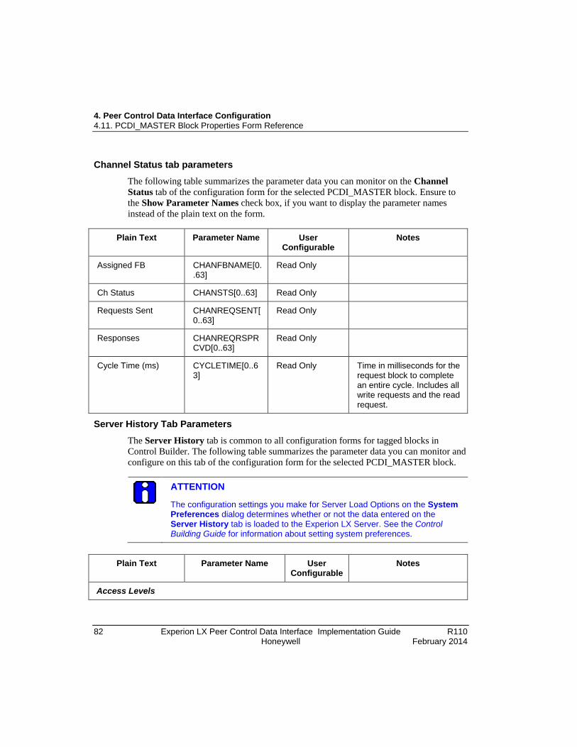
4. Peer Control Data Interface Configuration 4.11. PCDI_MASTER Block Properties Form Reference
82 Experion LX Peer Control Data Interface Implementation Guide R110 Honeywell February 2014
Channel Status tab parameters The following table summarizes the parameter data you can monitor on the Channel Status tab of the configuration form for the selected PCDI_MASTER block. Ensure to the Show Parameter Names check box, if you want to display the parameter names instead of the plain text on the form.
Plain Text Parameter Name User
Configurable Notes
Assigned FB CHANFBNAME[0..63]
Read Only
Ch Status CHANSTS[0..63] Read Only
Requests Sent CHANREQSENT[0..63]
Read Only
Responses CHANREQRSPRCVD[0..63]
Read Only
Cycle Time (ms) CYCLETIME[0..63]
Read Only Time in milliseconds for the request block to complete an entire cycle. Includes all write requests and the read request.
Server History Tab Parameters The Server History tab is common to all configuration forms for tagged blocks in Control Builder. The following table summarizes the parameter data you can monitor and configure on this tab of the configuration form for the selected PCDI_MASTER block.
ATTENTION
The configuration settings you make for Server Load Options on the System Preferences dialog determines whether or not the data entered on the Server History tab is loaded to the Experion LX Server. See the Control Building Guide for information about setting system preferences.
Plain Text Parameter Name User
Configurable Notes
Access Levels

4. Peer Control Data Interface Configuration 4.11. PCDI_MASTER Block Properties Form Reference
R110 Experion LX Peer Control Data Interface Implementation Guide 83 February 2014 Honeywell
Plain Text Parameter Name User Configurable
Notes
Control Level SCANCTRLLVL Yes Indicates Server control level to be associated with this function.
History Configuration
Number of History Parameters
HIST.NUMPARAMS Yes Defines number of history parameters to be included in History Configuration table.
Parameter HIST.PARAM Yes Valid parameter name for a parameter associated with the given point that is to be collected and stored as historical data at predetermined intervals.
Description No Provides a brief description of the entered parameter.
FAST HIST.FAST Yes Select the Fast type of history collection.
STD HIST.STD Yes Select the Standard type of history collection.
EXTD HIST.EXTD Yes Select the Extended type of history collection.
EXC HIST.EXC Yes
(Station only)
Select the Exception type of history collection.
Gating Parameter HIST.GATEPARAM Yes Optional gating parameter to define conditions under which data for this parameter should be collected.
Gate State HIST.GATEVALUE Yes Defines gate state for configured gating parameter.

4. Peer Control Data Interface Configuration 4.11. PCDI_MASTER Block Properties Form Reference
84 Experion LX Peer Control Data Interface Implementation Guide R110 Honeywell February 2014
Plain Text Parameter Name User Configurable
Notes
Create New or Edit Existing Server Scripts (Button)
N/A Launch the Server scripting configuration utility.
Server Displays Tab Parameters
The Server Displays tab is common to all configuration forms for tagged blocks in Control Builder. The following table summarizes the parameter data you can monitor and configure on this tab of the configuration form for the selected PCDI_MASTER block.
ATTENTION
The configuration settings you make for Server Load Options on the System Preferences dialog determines whether or not the data entered on the Server Displays tab is loaded to the Experion LX Server. See the Control Building Guide for information about setting system preferences.
Plain Text Parameter Name User
Configurable Notes
Point Detail Display SCANPNTDTL Yes By default, a Display template is already entered into Point Detail Display box (for example, Sysdtlmbtcpdevicea). This template can be used for creating your own display or it can be used as is, provided that your function block name matches name built into detail display that is supplied as a template.

4. Peer Control Data Interface Configuration 4.11. PCDI_MASTER Block Properties Form Reference
R110 Experion LX Peer Control Data Interface Implementation Guide 85 February 2014 Honeywell
Plain Text Parameter Name User Configurable
Notes
Group Detail Display SCANGRPDTL Yes By default, a Display template is already entered into the Group Detail Display box (for example, Sysdtlmbtcpdevicea_fp). This template can be used for creating your own display or it can be used as is, provided that your function block name matches name built into detail display that is supplied as a template
Associated Display SCANASSOCDSP Yes Name of the Server display to be associated with this function block.
Trends
Number of Trends TREND.NUMPARAMS
Yes Defines the number of trend parameters to be included in the Trends Configuration table.
Trend # Yes Defines Trend number to be associated with this trend parameter
Pen Yes Defines color of pen that will be used to trace assigned parameter on Station Trend display.
Trend Parameter Yes Valid parameter name for a parameter associated with given point that is configured for history collection.
Description No Provides a brief description of the entered parameter.
Groups

4. Peer Control Data Interface Configuration 4.11. PCDI_MASTER Block Properties Form Reference
86 Experion LX Peer Control Data Interface Implementation Guide R110 Honeywell February 2014
Plain Text Parameter Name User Configurable
Notes
Number of Groups GROUP.NUMPARAMS
Yes Defines the number of group parameters to be included in Groups Configuration table.
Group # Yes Defines Group number to be associated with this group parameter.
Pos # Yes Defines number of position configured parameter will occupy in the Station Group display.
Group Parameter Yes Valid parameter name for a parameter associated with the given point that is configured in the system.
Description No Provides a brief description of the entered parameter.
Control Confirmation Tab Parameters
The Control Confirmation tab is common to all configuration forms for tagged blocks in Control Builder. If you have an optional Electronic Signature license, you can configure electronic signature information for the tagged block through this tab on the block's configuration form in Control Builder. Refer to the online help and the Station Configuration Guide for more information about the data on this tab.
The Electronic Signature function aligns with the identical Electronic Signatures function that is initiated through Quick Builder and Station for Server points. When this block is loaded to a controller, its control confirmation configuration (electronic signatures) is also loaded to the Server. This means you can view the control confirmation configuration for this tagged object in Station and also make changes to it. If you make changes through Station, you must initiate an Upload or Upload with Contents function through the Controller menu in Control Builder for the object in the Monitoring tab to synchronize changes in the Engineering Repository Database (ERDB).
Identification Tab Parameters The Identification tab is common to all configuration forms for blocks in Control Builder. The following table summarizes the parameter data you can monitor and configure on this tab of the configuration form for the selected PCDI_MASTER block.

4. Peer Control Data Interface Configuration 4.11. PCDI_MASTER Block Properties Form Reference
R110 Experion LX Peer Control Data Interface Implementation Guide 87 February 2014 Honeywell
Plain Text Parameter Name User
Configurable Notes
Name NAME Yes Unique block name consisting of up to 16 characters to identify the block. At least one character in the name must be a letter (A-Z).
Description DESC Yes Descriptive text appears on detail and group displays to uniquely describe this particular function block
Block Comment 1 BLCKCOMMENT1 Yes Comment to be associated with this block consisting of up to 40 characters.
Block Comment 2 BLCKCOMMENT2 Yes Comment to be associated with this block consisting of up to 40 characters.
Block Comment 3 BLCKCOMMENT3 Yes Comment to be associated with this block consisting of up to 40 characters.
Block Comment 4 BLCKCOMMENT4 Yes Comment to be associated with this block consisting of up to 40 characters.
Library No Identifies Control Builder Library that is source of template.
System Template No Identifies System Template that is source for this block.
Base Template No Identifies Base Template that is used for this block.
Created By CREATEDBY No Identifies user who created block, if operator security is implemented. Otherwise, may just show Default login.
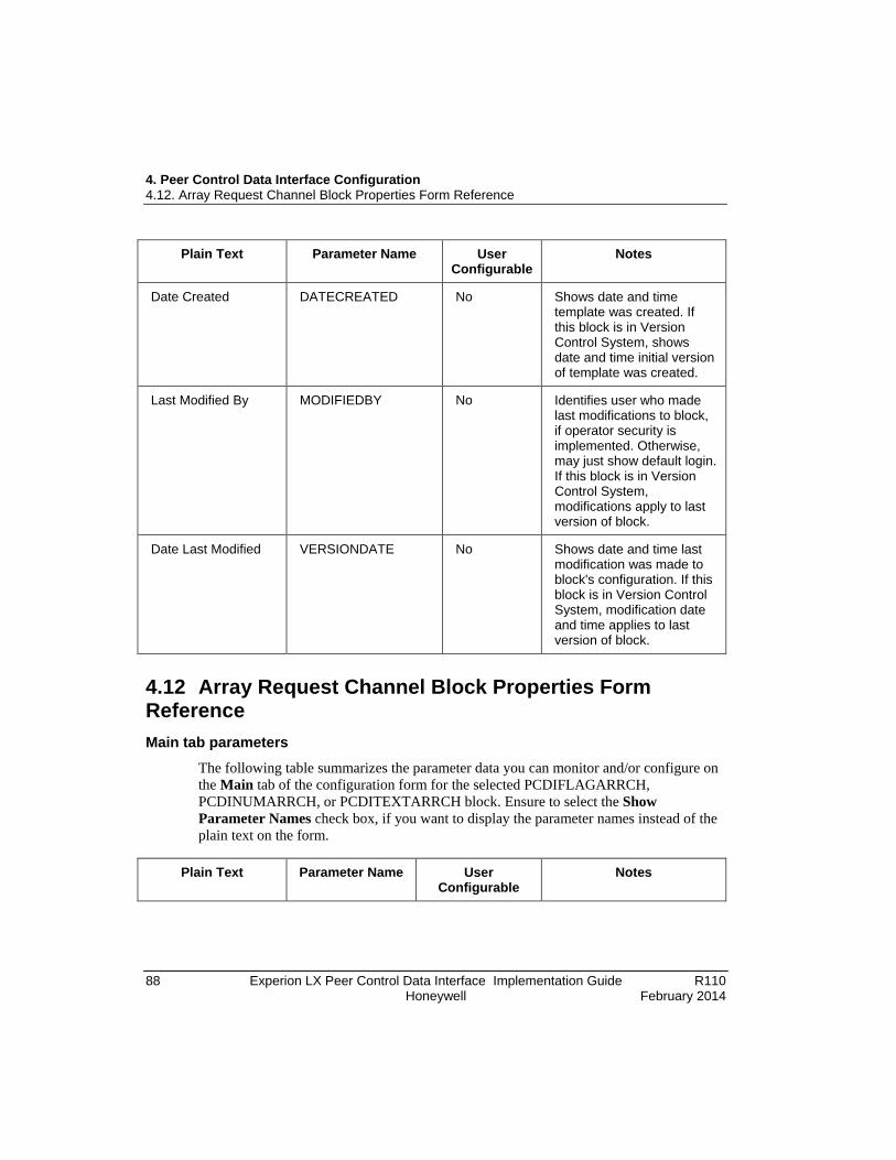
4. Peer Control Data Interface Configuration 4.12. Array Request Channel Block Properties Form Reference
88 Experion LX Peer Control Data Interface Implementation Guide R110 Honeywell February 2014
Plain Text Parameter Name User Configurable
Notes
Date Created DATECREATED No Shows date and time template was created. If this block is in Version Control System, shows date and time initial version of template was created.
Last Modified By MODIFIEDBY No Identifies user who made last modifications to block, if operator security is implemented. Otherwise, may just show default login. If this block is in Version Control System, modifications apply to last version of block.
Date Last Modified VERSIONDATE No Shows date and time last modification was made to block's configuration. If this block is in Version Control System, modification date and time applies to last version of block.
4.12 Array Request Channel Block Properties Form Reference Main tab parameters
The following table summarizes the parameter data you can monitor and/or configure on the Main tab of the configuration form for the selected PCDIFLAGARRCH, PCDINUMARRCH, or PCDITEXTARRCH block. Ensure to select the Show Parameter Names check box, if you want to display the parameter names instead of the plain text on the form.
Plain Text Parameter Name User
Configurable Notes
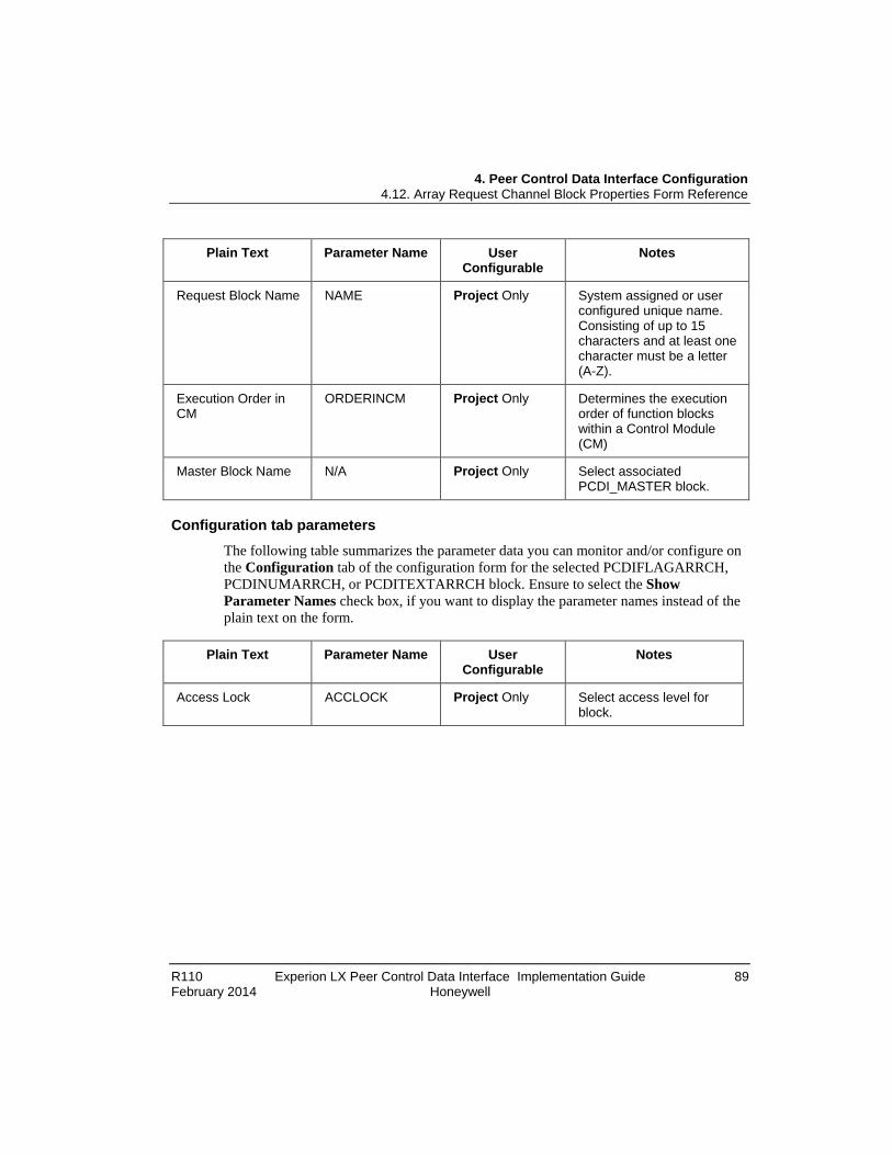
4. Peer Control Data Interface Configuration 4.12. Array Request Channel Block Properties Form Reference
R110 Experion LX Peer Control Data Interface Implementation Guide 89 February 2014 Honeywell
Plain Text Parameter Name User Configurable
Notes
Request Block Name NAME Project Only System assigned or user configured unique name. Consisting of up to 15 characters and at least one character must be a letter (A-Z).
Execution Order in CM
ORDERINCM Project Only Determines the execution order of function blocks within a Control Module (CM)
Master Block Name N/A Project Only Select associated PCDI_MASTER block.
Configuration tab parameters
The following table summarizes the parameter data you can monitor and/or configure on the Configuration tab of the configuration form for the selected PCDIFLAGARRCH, PCDINUMARRCH, or PCDITEXTARRCH block. Ensure to select the Show Parameter Names check box, if you want to display the parameter names instead of the plain text on the form.
Plain Text Parameter Name User
Configurable Notes
Access Lock ACCLOCK Project Only Select access level for block.
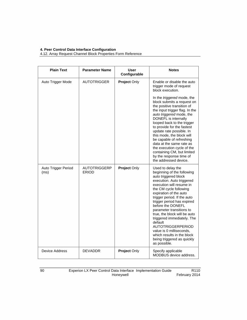
4. Peer Control Data Interface Configuration 4.12. Array Request Channel Block Properties Form Reference
90 Experion LX Peer Control Data Interface Implementation Guide R110 Honeywell February 2014
Plain Text Parameter Name User Configurable
Notes
Auto Trigger Mode AUTOTRIGGER Project Only Enable or disable the auto trigger mode of request block execution.
In the triggered mode, the block submits a request on the positive transition of the input trigger flag. In the auto triggered mode, the DONEFL is internally looped back to the trigger to provide for the fastest update rate possible. In this mode, the block will be capable of refreshing data at the same rate as the execution cycle of the containing CM, but limited by the response time of the addressed device.
Auto Trigger Period (ms)
AUTOTRIGGERPERIOD
Project Only Used to delay the beginning of the following auto triggered block execution. Auto triggered execution will resume in the CM cycle following expiration of the auto trigger period. If the auto trigger period has expired before the DONEFL parameter transitions to true, the block will be auto triggered immediately. The default AUTOTRIGGERPERIOD value is 0 milliseconds, which results in the block being triggered as quickly as possible.
Device Address DEVADDR Project Only Specify applicable MODBUS device address.

4. Peer Control Data Interface Configuration 4.12. Array Request Channel Block Properties Form Reference
R110 Experion LX Peer Control Data Interface Implementation Guide 91 February 2014 Honeywell
Plain Text Parameter Name User Configurable
Notes
Starting Element Index
STARTINDEX Project Only Set applicable start index value for given Array Request Channel block
Long CONVTOLONGI Project Only Applicable to PCDINUMARRCH block only.
Enable or disable convert to long function.
ASCII Conversion CONVTOASCII Project Only Applicable to PCDITEXTARRCH block only.
Enable or disable convert text to ASCII function.
Number of Flag Values
NFLAG Project Only Applicable to PCDIFLAGARRCH block only.
Define number of flags to read. Range is 1 to 1968.
Number of Numeric Values
NNUMERIC Project Only Applicable to PCDINUMARRCH block only.
Define number of numeric values to read. Valid values are actually dependent upon the STARTINDEX.

4. Peer Control Data Interface Configuration 4.12. Array Request Channel Block Properties Form Reference
92 Experion LX Peer Control Data Interface Implementation Guide R110 Honeywell February 2014
Plain Text Parameter Name User Configurable
Notes
Number of String Values
NSTRING Project Only Applicable to PCDITEXTARRCH block only.
Define number of string values to read.
The number of strings times the number of characters per string may not exceed 120 Unicode characters or 240 ASCII characters.
Char Length of String Values
STRLEN Project Only Applicable to PCDITEXTARRCH block only.
Define number of characters per string
The number of strings times the number of characters per string may not exceed 120 Unicode characters or 240 ASCII characters.
Read/Write Option WRITEOPT Project Only Select read/write setting for block.
Scaling/Substitution tab parameters
The following table summarizes the parameter data you can monitor and/or configure on the Scaling/Substitution or Substitution tab of the configuration form for the selected PCDINUMARRCH, or PCDIFLAGARRCH or PCDITEXTARRCH block. Ensure to select the Show Parameter Names check box, if you want to display the parameter names instead of the plain text on the form.
Plain Text Parameter Name User
Configurable Notes

4. Peer Control Data Interface Configuration 4.12. Array Request Channel Block Properties Form Reference
R110 Experion LX Peer Control Data Interface Implementation Guide 93 February 2014 Honeywell
Plain Text Parameter Name User Configurable
Notes
Default Substitution Type
SUBVALTYPE Project Only Select what value to substitute when error occurs.
Default Substitution Value
SUBVAL Project Only Applicable to PCDINUMARRCH and PCDITEXTARRCH blocks only.
Set value to use when error occurs.
Set to ON on error SUBVAL Project Only Applicable to PCDIFLAGARRCH block only.
Enable or disable set to ON on error function.
PV High Range (in Engineering Units)
PVEUHI Project Only Applicable to PCDINUMARRCH block only.
Specify high range value in Engineering Units.
PV Low Range (in Engineering Units)
PVEULO Project Only Applicable to PCDINUMARRCH block only.
Specify low range value in Engineering Units.
PV Raw High Range PVRAWHI Project Only Applicable to PCDINUMARRCH block only.
PV raw high range value.
PV Raw Low Range PVRAWLO Project Only Applicable to PCDINUMARRCH block only.
PV raw low range value.

4. Peer Control Data Interface Configuration 4.12. Array Request Channel Block Properties Form Reference
94 Experion LX Peer Control Data Interface Implementation Guide R110 Honeywell February 2014
Plain Text Parameter Name User Configurable
Notes
Engineering Unit Description
EUDESC Project Only Applicable to PCDINUMARRCH block only.
Provide description of applicable Engineering Unit.
Substitution Type ELEMSUBVALTYPE
Project Only Substitution on error is supported with common SUBVALTYPE and SUBVAL parameters that may be overridden with parameters ELEMSUBVALTYPE and ELEMSUBVAL on per element basis.
Substitution Value ELEMSUBVAL Project Only See row above. Status/Data tab parameters
The following table summarizes the parameter data you can monitor on the Status/Data tab of the configuration form for the selected PCDIFLAGARRCH, PCDINUMARRCH, or PCDITEXTARRCH block. Ensure to select the Show Parameter Names check box, if you want to display the parameter names instead of the plain text on the form.
Plain Text Parameter Name User
Configurable Notes
Ch Status CHANSTS Monitoring Only See parameter definition for details.
Error Flag ERRFL Monitoring Only Enable or disable error flag function. When set, indicates that ERRCODE is currently active.
Last Error ERRCODE Monitoring Only See parameter definition for details.
Bad PV Flag BADPVFL Monitoring Only
Time of Last Error LASTERRTIME No

4. Peer Control Data Interface Configuration 4.12. Array Request Channel Block Properties Form Reference
R110 Experion LX Peer Control Data Interface Implementation Guide 95 February 2014 Honeywell
Plain Text Parameter Name User Configurable
Notes
Process Value PVFL Monitoring Only Applicable to PCDIFLAGARRCH block only.
Process Value PV Monitoring Only Applicable to PCDINUMARRCH block only.
Process Value Raw PVRAW Monitoring Only Applicable to PCDINUMARRCH block only.
Process Value STR[1..16 Monitoring Only Applicable to PCDITEXTARRCH block only.
Identification tab parameters
The Identification tab is common to all configuration forms for basic blocks in Control Builder. The following table summarizes the parameter data that you can monitor and configure in the configuration form of this tab, for the selected Array Request Channel block.
Plain Text Parameter Name User
Configurable Notes
Name NAME Yes Unique block name consisting of up to 15 characters to identify the block. At least one character in the name must be a letter (A-Z).
Block Comment 1 BLCKCOMMENT1 Yes Comment to be associated with this block consisting of up to 40 characters.
Block Comment 2 BLCKCOMMENT2 Yes Comment to be associated with this block consisting of up to 40 characters.
Block Comment 3 BLCKCOMMENT3 Yes Comment to be associated with this block consisting of up to 40 characters.

4. Peer Control Data Interface Configuration 4.12. Array Request Channel Block Properties Form Reference
96 Experion LX Peer Control Data Interface Implementation Guide R110 Honeywell February 2014
Plain Text Parameter Name User Configurable
Notes
Block Comment 4 BLCKCOMMENT4 Yes Comment to be associated with this block consisting of up to 40 characters.
Library No Identifies Control Builder Library that is source of template.
System Template No Identifies System Template that is source for this block.
Base Template No Identifies Base Template that is used for this block.
Dependencies tab parameters
The Dependencies tab is common to all configuration forms for basic blocks in Control Builder. For more information about this tab, refer to the online help and the Control Builder User's Guide.
Block pins tab parameters The Block Pins tab is common to all configuration forms for basic blocks in Control Builder. For more information about this tab, refer to the online help and the Control Builder User's Guide.
Configuration Parameters tab parameters The Configuration Parameters tab is common to all configuration forms for basic blocks in Control Builder. For more information about this tab, refer to the online help and the Control Builder User's Guide.
Monitoring Parameters tab parameters The Monitoring Parameters tab is common to all configuration forms for basic blocks in Control Builder. For more information about this tab, refer to the online help and the Control Builder User's Guide.
Block Preferences tab parameters The Block Preferences tab is common to all configuration forms for basic blocks in Control Builder. For more information about this tab, refer to the online help and the Control Builder User's Guide.

4. Peer Control Data Interface Configuration 4.12. Array Request Channel Block Properties Form Reference
R110 Experion LX Peer Control Data Interface Implementation Guide 97 February 2014 Honeywell
Template Defining tab parameters The Template Defining tab is common to all configuration forms for basic blocks in Control Builder. For more information about this tab, refer to the online help and the Control Builder User's Guide.

R110 Experion LX Peer Control Data Interface Implementation Guide 99 February 2014 Honeywell
5. Peer Control Data Interface Operation
5.1 Monitoring Peer Control Data Interface Functions through Station Displays Using Station Detail displays
The Experion LX Server Station application includes pre-configured Detail displays for the PCDI_MASTER function blocks. These displays are the default entries for the Point Detail Page parameter on the Server Displays tab of the configuration form. Once you establish communications with a peer device, you can begin monitoring the status of any component that has been loaded as a part of the Control Strategy to an Experion LX Controller with points registered in the Experion LX Server. The Detail displays let you quickly view the component's current state, fault status, and pertinent configuration data.
REFERENCE - INTERNAL
Refer to the In Operator's Guide for detailed information about calling up, navigating, and viewing displays in Station.
Graphical example of PCDI_MASTER block detail display
The following figure shows the faceplate for a PCDI master device displaying its component state. See the following tables for description of illustration callouts and peer device text messages.

5. Peer Control Data Interface Operation 5.1. Monitoring Peer Control Data Interface Functions through Station Displays
100 Experion LX Peer Control Data Interface Implementation Guide R110 Honeywell February 2014
Figure 5 Sample PCDI Master Device Detail Display
Table 3 Description of Figure 5 Callouts.
Callout Description
1 Module name configured through Control Builder.
2 Module description configured through Control Builder.
3 Peer device text indicating current general status of functions.
4 LEDs show current connection status.
5 Shows any alarm condition. Click button to acknowledge alarm.
6 Identifies the connection in use.
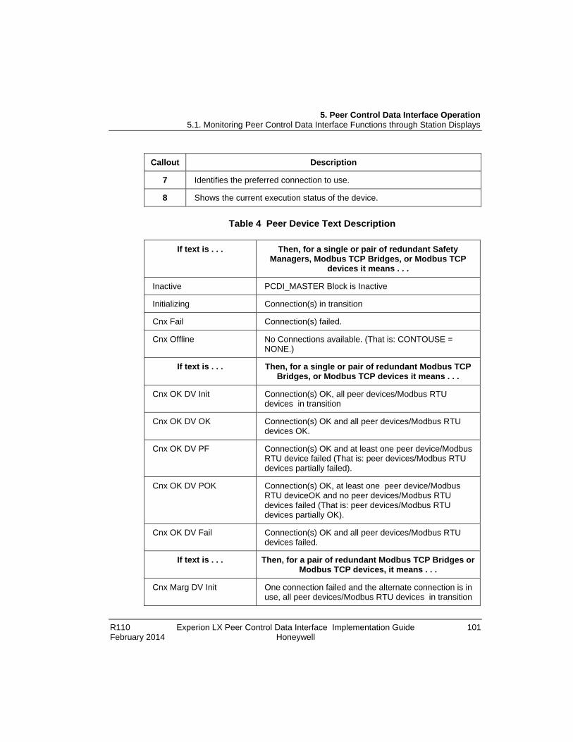
5. Peer Control Data Interface Operation 5.1. Monitoring Peer Control Data Interface Functions through Station Displays
R110 Experion LX Peer Control Data Interface Implementation Guide 101 February 2014 Honeywell
Callout Description
7 Identifies the preferred connection to use.
8 Shows the current execution status of the device.
Table 4 Peer Device Text Description
If text is . . . Then, for a single or pair of redundant Safety Managers, Modbus TCP Bridges, or Modbus TCP
devices it means . . .
Inactive PCDI_MASTER Block is Inactive
Initializing Connection(s) in transition
Cnx Fail Connection(s) failed.
Cnx Offline No Connections available. (That is: CONTOUSE = NONE.)
If text is . . . Then, for a single or pair of redundant Modbus TCP Bridges, or Modbus TCP devices it means . . .
Cnx OK DV Init Connection(s) OK, all peer devices/Modbus RTU devices in transition
Cnx OK DV OK Connection(s) OK and all peer devices/Modbus RTU devices OK.
Cnx OK DV PF Connection(s) OK and at least one peer device/Modbus RTU device failed (That is: peer devices/Modbus RTU devices partially failed).
Cnx OK DV POK Connection(s) OK, at least one peer device/Modbus RTU deviceOK and no peer devices/Modbus RTU devices failed (That is: peer devices/Modbus RTU devices partially OK).
Cnx OK DV Fail Connection(s) OK and all peer devices/Modbus RTU devices failed.
If text is . . . Then, for a pair of redundant Modbus TCP Bridges or Modbus TCP devices, it means . . .
Cnx Marg DV Init One connection failed and the alternate connection is in use, all peer devices/Modbus RTU devices in transition

5. Peer Control Data Interface Operation 5.1. Monitoring Peer Control Data Interface Functions through Station Displays
102 Experion LX Peer Control Data Interface Implementation Guide R110 Honeywell February 2014
Cnx Marg DV OK One connection failed and the alternate connection is in use, all peer devices/Modbus RTU devices OK.
Cnx Marg DV PF One connection failed and the alternate connection is in use and at least one peer device/Modbus RTU device failed (That is: peer devices/Modbus RTU devices partially failed).
Cnx Marg DV POK One connection failed and the alternate connection is in use and at least one peer device/Modbus RTU device OK and no peer devices/Modbus RTU devices failed (That is: peer devices/Modbus RTU devices partially OK).
Cnx Marg DV Fail One connection failed and the alternate connection is in use and all peer devices/Modbus RTU devices failed.
If text is . . . Then, for a single or pair of redundant Safety Managers, it means . . .
Cnx OK SM Init Connection(s) OK, all Safety Manager devices in transition
Cnx OK SM OK Connection(s) OK and all Safety Manager devices OK.
Cnx OK SM PF Connection(s) OK and at least one Safety Manager device failed (That is: Safety Manager devices partially failed).
Cnx OK SM POK Connection(s) OK, at least one Safety Manager device OK and no Safety Manager devices idle or failed (That is: Safety Manager devices partially OK).
Cnx OK SM Fail Connection(s) OK and all Safety Manager devices failed.
Cnx OK SM Idle Connection(s) OK, at least one Safety Manager device idle and no Safety Manager device failed.
If text is . . . Then, for a pair of redundant Safety Managers, it means . . .
Cnx Marg SM Init One connection failed and the alternate connection is in use, all Safety Manager devices in transition
Cnx Marg SM OK One connection failed and the alternate connection is in use, all Safety Manager devices OK.
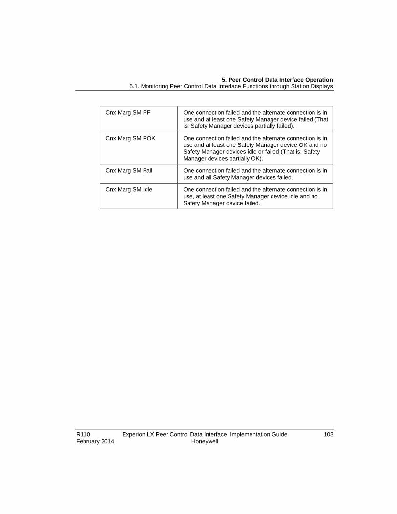
5. Peer Control Data Interface Operation 5.1. Monitoring Peer Control Data Interface Functions through Station Displays
R110 Experion LX Peer Control Data Interface Implementation Guide 103 February 2014 Honeywell
Cnx Marg SM PF One connection failed and the alternate connection is in use and at least one Safety Manager device failed (That is: Safety Manager devices partially failed).
Cnx Marg SM POK One connection failed and the alternate connection is in use and at least one Safety Manager device OK and no Safety Manager devices idle or failed (That is: Safety Manager devices partially OK).
Cnx Marg SM Fail One connection failed and the alternate connection is in use and all Safety Manager devices failed.
Cnx Marg SM Idle One connection failed and the alternate connection is in use, at least one Safety Manager device idle and no Safety Manager device failed.

5. Peer Control Data Interface Operation 5.1. Monitoring Peer Control Data Interface Functions through Station Displays
104 Experion LX Peer Control Data Interface Implementation Guide R110 Honeywell February 2014
Graphical example of viewing Last Error on Channel Status tab of PCDI_MASTER block in Station
Figure 6 Example View of Last Error on Channel Status Tab in Station
Step Action
1 Click the Config Details tab on the Detail Display.
2 Use the scroll bar to move to right side.
3 Click the Channel Status tab.
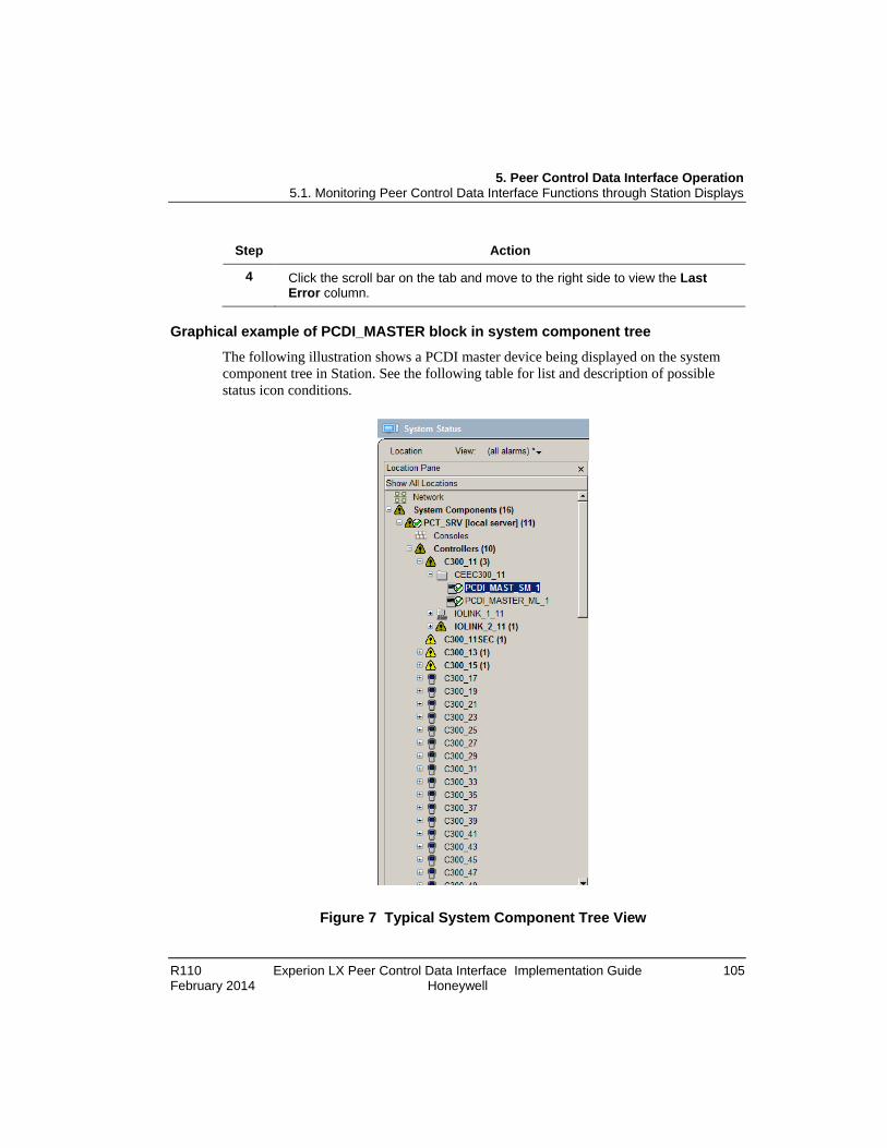
5. Peer Control Data Interface Operation 5.1. Monitoring Peer Control Data Interface Functions through Station Displays
R110 Experion LX Peer Control Data Interface Implementation Guide 105 February 2014 Honeywell
Step Action
4 Click the scroll bar on the tab and move to the right side to view the Last Error column.
Graphical example of PCDI_MASTER block in system component tree
The following illustration shows a PCDI master device being displayed on the system component tree in Station. See the following table for list and description of possible status icon conditions.
Figure 7 Typical System Component Tree View

5. Peer Control Data Interface Operation 5.1. Monitoring Peer Control Data Interface Functions through Station Displays
106 Experion LX Peer Control Data Interface Implementation Guide R110 Honeywell February 2014
Table 5 Status Icon Description
If Status Icon is . . . Then, It Means
Connection(s) OK, all peer devices/Modbus RTU devices OK
Connection(s) marginal or peer devices/Modbus RTU devices marginal
Connection(s) failed or any peer devices/Modbus RTU devices failed
Master Block is Inactive
Using Station System Status Display
Like the Detail displays, the System Status Display supports the integration of PCDI Master Device block generated notifications and events. It is integrated with Experion LX component data and is for the most part self-explanatory. PCDI channel blocks will report channel alarms through the Device Block they are assigned to. Channel alarms will be returned to normal if alarm condition no longer exists, the channel block state is changed to inactive, or the channel block is deleted. Use this display to get a quick review of recent actions that have been initiated within the system.
Graphical example of PCDI_MASTER block in Alarm pane of System Status Display
The following illustration shows alarm events for PCDI master device. See the following table for list and description of possible Peer Control Data Interface event subtypes in the Experion LX Notification System based on a per PCDI Master Device block basis.

5. Peer Control Data Interface Operation 5.1. Monitoring Peer Control Data Interface Functions through Station Displays
R110 Experion LX Peer Control Data Interface Implementation Guide 107 February 2014 Honeywell
Figure 8 System Status Display Alarm Pane

5. Peer Control Data Interface Operation 5.1. Monitoring Peer Control Data Interface Functions through Station Displays
108 Experion LX Peer Control Data Interface Implementation Guide R110 Honeywell February 2014
Table 6 Peer Control Data Interface Event Subtypes
Legend: • single Modbus device = single MODBUS TCP Bridge, single MODBUS TCP
Device or Safety Manager
• redundant pair of Modbus devices = redundant MODBUS TCP Bridge, redundant MODBUS TCP Device, or redundant Safety Manager
Peer Control Data
Interface Event Subtype
Cond Prty Auxiliary Descriptor Event Description
Connection Fail DIAG H Connection(s) FAIL For a single Modbus device, an alarm is generated when a single Modbus device connection has failed.
For a redundant pair of Modbus devices, an alarm is generated when both connections of a redundant pair of Modbus devices have failed.
Connection Warning DIAG H Connection Warning For a redundant pair of Modbus devices, an alarm is generated when a single connection has failed and the alternate connection is in use.
Single Device FAIL DIAG H Single Device FAIL For a single MODBUS TCP Device, an alarm is generated when the single connection is OK, but the single MODBUS TCP Device has failed.
Primary Device FAIL DIAG H Primary Device FAIL For a redundant MODBUS TCP Device, an alarm is generated when the primary connection is OK, but the primary MODBUS

5. Peer Control Data Interface Operation 5.1. Monitoring Peer Control Data Interface Functions through Station Displays
R110 Experion LX Peer Control Data Interface Implementation Guide 109 February 2014 Honeywell
Peer Control Data Interface Event
Subtype
Cond Prty Auxiliary Descriptor Event Description
TCP Device has failed.
Secondary Device FAIL
DIAG H Secondary Device FAIL
For a redundant MODBUS TCP Device, an alarm is generated when the secondary connection is OK, but the secondary MODBUS TCP Device has failed.
Primary Connection is forced
DIAG H Secondary Offline For a redundant pair of Modbus devices, an alarm is generated when CONTOUSE is set to Primary.
Secondary Connection is forced in use
DIAG H Primary Offline For a redundant pair of Modbus devices, an alarm is generated when CONTOUSE is set to Secondary.
Primary and secondary connections are forced offline
DIAG H No Connections Available
For a single Modbus device or a redundant pair of Modbus devices, an alarm is generated when CONTOUSE is set to NONE.
Primary All UID FAIL DIAG H Primary All UID FAIL For a single MODBUS TCP Bridge, an alarm is generated when all Modbus RTU devices on the primary connection have failed.
For a redundant MODBUS TCP Bridge, an alarm is generated when all Modbus RTU devices on primary connection have failed, CONINUSE is switched to Secondary, the alarm will not return to
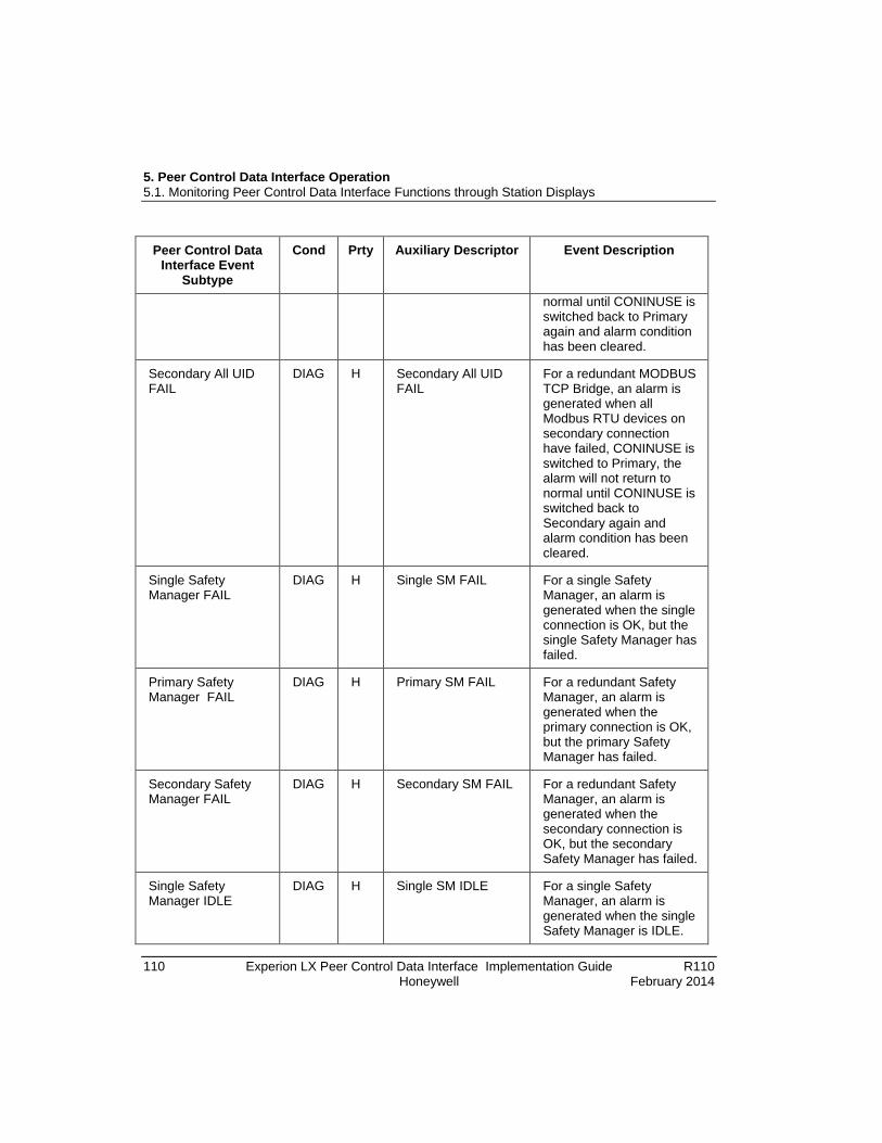
5. Peer Control Data Interface Operation 5.1. Monitoring Peer Control Data Interface Functions through Station Displays
110 Experion LX Peer Control Data Interface Implementation Guide R110 Honeywell February 2014
Peer Control Data Interface Event
Subtype
Cond Prty Auxiliary Descriptor Event Description
normal until CONINUSE is switched back to Primary again and alarm condition has been cleared.
Secondary All UID FAIL
DIAG H Secondary All UID FAIL
For a redundant MODBUS TCP Bridge, an alarm is generated when all Modbus RTU devices on secondary connection have failed, CONINUSE is switched to Primary, the alarm will not return to normal until CONINUSE is switched back to Secondary again and alarm condition has been cleared.
Single Safety Manager FAIL
DIAG H Single SM FAIL For a single Safety Manager, an alarm is generated when the single connection is OK, but the single Safety Manager has failed.
Primary Safety Manager FAIL
DIAG H Primary SM FAIL For a redundant Safety Manager, an alarm is generated when the primary connection is OK, but the primary Safety Manager has failed.
Secondary Safety Manager FAIL
DIAG H Secondary SM FAIL For a redundant Safety Manager, an alarm is generated when the secondary connection is OK, but the secondary Safety Manager has failed.
Single Safety Manager IDLE
DIAG H Single SM IDLE For a single Safety Manager, an alarm is generated when the single Safety Manager is IDLE.

5. Peer Control Data Interface Operation 5.1. Monitoring Peer Control Data Interface Functions through Station Displays
R110 Experion LX Peer Control Data Interface Implementation Guide 111 February 2014 Honeywell
Peer Control Data Interface Event
Subtype
Cond Prty Auxiliary Descriptor Event Description
Primary Safety Manager IDLE
DIAG H Primary SM IDLE For a redundant Safety Manager, an alarm is generated when the primary Safety Manager is IDLE.
Secondary Safety Manager IDLE
DIAG H Secondary SM IDLE For a redundant Safety Manager, an alarm is generated when the secondary Safety Manager is IDLE.
Serial Device [0..15] Fail
DIAG H UID xxx FAIL For a single MODBUS TCP Bridge or a redundant MODBUS TCP Bridge with up to 16 Modbus RTU devices, an alarm is generated when a Modbus RTU device has failed.
(xxx is Modbus TCP Bridge Modbus RTU device Unit ID, range 1..247 and 255)
Serial Device [0..15] Disabled
DIAG H UID xxx Disabled For a single MODBUS TCP Bridge or a redundant MODBUS TCP Bridge with up to 16 Modbus RTU devices, an alarm is generated when a Modbus RTU device has been disabled.
(xxx is Modbus TCP Bridge Modbus RTU device Unit ID, range 1..247 and 255)
Channel Fail [0..63] DIAG H Channel xxFAIL For a single Modbus device or a redundant pair of Modbus devices, an alarm is generated when an assigned channel has failed.
5. Peer Control Data Interface Operation 5.2. Monitoring PCDI Functions through Monitoring Tab in Control Builder
112 Experion LX Peer Control Data Interface Implementation Guide R110 Honeywell February 2014
Peer Control Data Interface Event
Subtype
Cond Prty Auxiliary Descriptor Event Description
(xx is assigned channel number, range 0..63).
REFERENCE - INTERNAL
Refer to the Operator's Guide for more information about using the Station interface.
5.2 Monitoring PCDI Functions through Monitoring Tab in Control Builder Activating/inactivating PCDI_MASTER device
Perform the following procedure to change the state of a PCDI_MASTER device through the Monitoring tab in Control Builder.
Prerequisites • You have logged on with sufficient privileges to make changes in a control strategy.
• You have loaded a control strategy to the Controller and can view the PCDI_MASTER device through the Monitoring tab of Control Builder.
Considerations • Activating a PCDI_MASTER device generates a state event change and resumes the
module's normal periodic processing.
• Inactivating a PCDI_MASTER device generates a state event change; blocks channel access to flag, numeric, and string data from the device; and sets channel depending on SUBVALTYPE, as well as setting associated BADPVFL.

5. Peer Control Data Interface Operation 5.2. Monitoring PCDI Functions through Monitoring Tab in Control Builder
R110 Experion LX Peer Control Data Interface Implementation Guide 113 February 2014 Honeywell
To activate or inactivate a PCDI_MASTER device
Step Action
1 • Right-click the PCDI_MASTER device icon (green) and click Inactivate>Selected Item(s) on the menu.
Or,
• Right click the PCDI_MASTER device icon (blue) and click the Activate>Selected Item(s) on the menu.
2 Click the Yes button to confirm the action in the Change State dialog.
3 • Wait for PCDI_MASTER device icon to turn blue/inactive.
Or,
• Wait for PCDI_MASTER device icon to turn green/active.
4 This completes the procedure to activate or inactivate the PCDI_Master device.
PCDI_MASTER device block icon appearances
The following table summarizes the various appearances that a PCDI_MASTER device block icon in Control Builder can assume based on configuration, view, and current PCDI_MASTER device operating state and status.
If Icon is . . . Then, it represents . . . And, Module
State (IOMSTATE)* Is. . .
Project Tab
(gray) PCDI_MASTER non-redundant bridge configured for operation in Project.
N/A
(gray) PCDI_MASTER non-redundant MODBUS TCP device configured for operation in Project.
N/A
(gray) PCDI_MASTER non-redundant Safety Manager configured for operation in Project.
N/A
(gray) PCDI_MASTER redundant bridges configured for operation in Project.
N/A

5. Peer Control Data Interface Operation 5.2. Monitoring PCDI Functions through Monitoring Tab in Control Builder
114 Experion LX Peer Control Data Interface Implementation Guide R110 Honeywell February 2014
If Icon is . . . Then, it represents . . . And, Module State (IOMSTATE)*
Is. . .
(gray) PCDI_MASTER redundant MODBUS TCP devices configured for operation in Project.
N/A
(gray) PCDI_MASTER redundant Safety Managersconfigured for operation in Project.
N/A
Monitoring Tab
(gray) PCDI_MASTER non-redundant bridge is loaded, but not monitoring
N/A
(blue) PCDI_MASTER non-redundant MODBUS TCP device is loaded, but not monitoring
N/A
(green) PCDI_MASTER non-redundant Safety Manager is loaded, but not monitoring
N/A
(gray) PCDI_MASTER redundant bridges are loaded, but not monitoring
N/A
(gray) PCDI_MASTER redundant MODBUS TCP devices are loaded, but not monitoring
N/A
(gray) PCDI_MASTER redundant Safety Managers are loaded, but not monitoring
N/A
(blue) PCDI_MASTER non-redundant bridge is inactive
INACTIVE
(blue)
PCDI_MASTER non-redundant MODBUS TCP device is inactive
INACTIVE
(blue) PCDI_MASTER non-redundant Safety Manager is inactive
INACTIVE
(blue)
PCDI_MASTER redundant bridges are inactive INACTIVE/INACTIVE
(blue)
PCDI_MASTER redundant MODBUS TCP devices are inactive
INACTIVE/INACTIVE

5. Peer Control Data Interface Operation 5.2. Monitoring PCDI Functions through Monitoring Tab in Control Builder
R110 Experion LX Peer Control Data Interface Implementation Guide 115 February 2014 Honeywell
If Icon is . . . Then, it represents . . . And, Module State (IOMSTATE)*
Is. . .
(blue)
PCDI_MASTER redundant Safety Managers are inactive
INACTIVE/INACTIVE
(green) PCDI_MASTER non-redundant bridge is active OK
(green) PCDI_MASTER non-redundant MODBUS TCP device is active
OK
(green) PCDI_MASTER non-redundant Safety Manager is active
OK
(green)
PCDI_MASTER redundant bridges are active OK/OK
(green) PCDI_MASTER redundant MODBUS TCP devices are active
OK/OK
(green) PCDI_MASTER redundant Safety Managers are active
OK/OK
(yellow) PCDI_MASTER non-redundant bridge is not used
STBY
(yellow)
PCDI_MASTER non-redundant MODBUS TCP device is not used.
STBY
(yellow) PCDI_MASTER non-redundant Safety Manager is not used
STBY
(yellow/yellow) PCDI_MASTER redundant bridges are not used
STBY/STBY
(yellow/yellow) PCDI_MASTER redundant MODBUS TCP devices are not used
STBY/STBY
(yellow/yellow) PCDI_MASTER redundant Safety Managers are not used
STBY/STBY
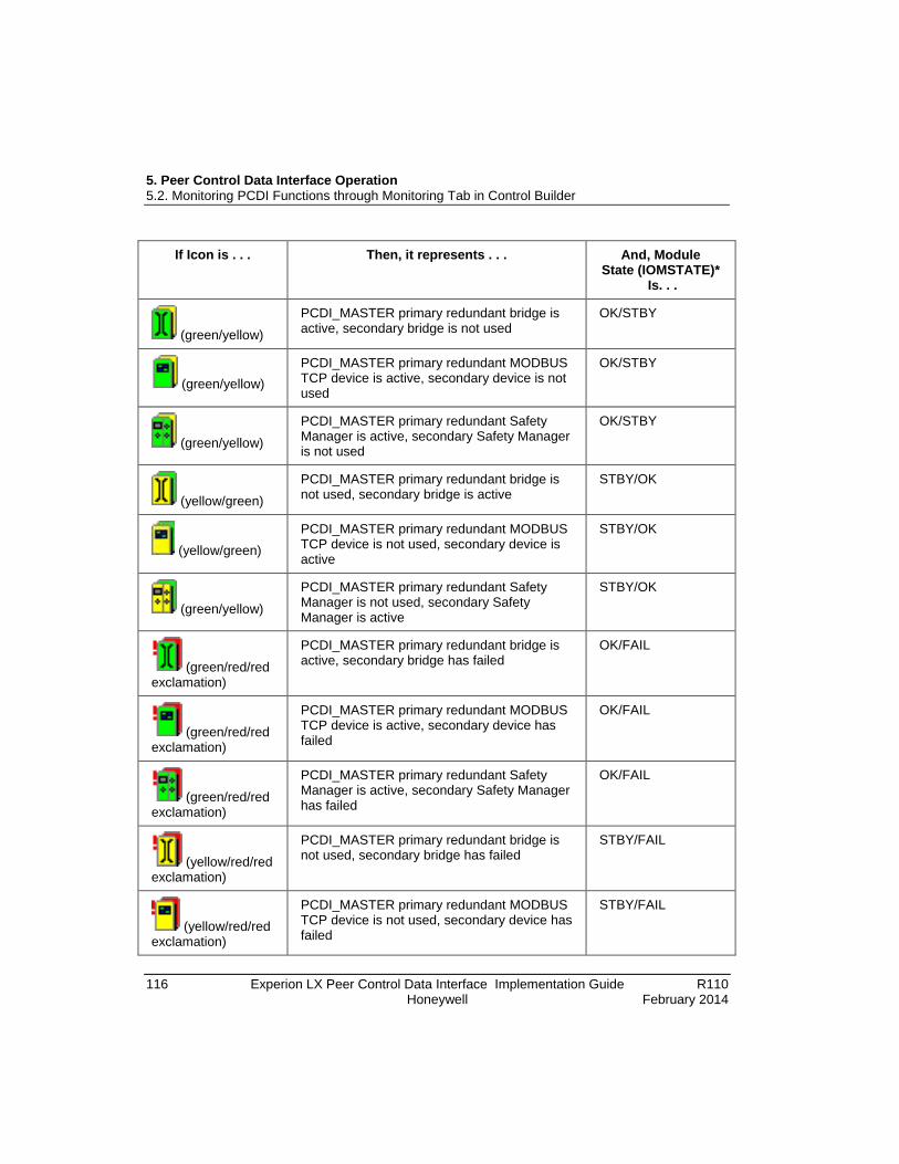
5. Peer Control Data Interface Operation 5.2. Monitoring PCDI Functions through Monitoring Tab in Control Builder
116 Experion LX Peer Control Data Interface Implementation Guide R110 Honeywell February 2014
If Icon is . . . Then, it represents . . . And, Module State (IOMSTATE)*
Is. . .
(green/yellow) PCDI_MASTER primary redundant bridge is active, secondary bridge is not used
OK/STBY
(green/yellow) PCDI_MASTER primary redundant MODBUS TCP device is active, secondary device is not used
OK/STBY
(green/yellow) PCDI_MASTER primary redundant Safety Manager is active, secondary Safety Manager is not used
OK/STBY
(yellow/green) PCDI_MASTER primary redundant bridge is not used, secondary bridge is active
STBY/OK
(yellow/green) PCDI_MASTER primary redundant MODBUS TCP device is not used, secondary device is active
STBY/OK
(green/yellow) PCDI_MASTER primary redundant Safety Manager is not used, secondary Safety Manager is active
STBY/OK
(green/red/red exclamation)
PCDI_MASTER primary redundant bridge is active, secondary bridge has failed
OK/FAIL
(green/red/red exclamation)
PCDI_MASTER primary redundant MODBUS TCP device is active, secondary device has failed
OK/FAIL
(green/red/red exclamation)
PCDI_MASTER primary redundant Safety Manager is active, secondary Safety Manager has failed
OK/FAIL
(yellow/red/red exclamation)
PCDI_MASTER primary redundant bridge is not used, secondary bridge has failed
STBY/FAIL
(yellow/red/red exclamation)
PCDI_MASTER primary redundant MODBUS TCP device is not used, secondary device has failed
STBY/FAIL

5. Peer Control Data Interface Operation 5.2. Monitoring PCDI Functions through Monitoring Tab in Control Builder
R110 Experion LX Peer Control Data Interface Implementation Guide 117 February 2014 Honeywell
If Icon is . . . Then, it represents . . . And, Module State (IOMSTATE)*
Is. . .
(yellow/red/red exclamation)
PCDI_MASTER primary redundant Safety Manager is not used, secondary Safety Manager has failed
STBY/FAIL
(red/green/red exclamation)
PCDI_MASTER primary redundant bridge has failed, secondary bridge is active
FAIL/OK
(red/green/red exclamation)
PCDI_MASTER primary redundant MODBUS TCP device has failed, secondary device is active
FAIL/OK
(red/green/red exclamation)
PCDI_MASTER primary redundant Safety Manager has failed, secondary Safety Manager is active
FAIL/OK
(red/yellow/red exclamation)
PCDI_MASTER primary redundant bridge has failed, secondary bridge is not used
FAIL/STBY
(red/yellow/red exclamation)
PCDI_MASTER primary redundant MODBUS TCP device has failed, secondary device is not used
FAIL/STBY
(red/yellow/red exclamation)
PCDI_MASTER primary redundant Safety Manager has failed, secondary Safety Manager is not used
FAIL/STBY
(red/red/red exclamation)
PCDI_MASTER primary redundant bridge has failed, secondary bridge has failed
FAIL
(red/red/red exclamation)
PCDI_MASTER primary redundant MODBUS TCP device has failed, secondary device has failed
FAIL
(red/red/red exclamation)
PCDI_MASTER primary redundant Safety Manager has failed, secondary Safety Manager has failed
FAIL

5. Peer Control Data Interface Operation 5.2. Monitoring PCDI Functions through Monitoring Tab in Control Builder
118 Experion LX Peer Control Data Interface Implementation Guide R110 Honeywell February 2014
If Icon is . . . Then, it represents . . . And, Module State (IOMSTATE)*
Is. . .
(red/black exclamation)
PCDI_MASTER non-redundant bridge with communication failure
FAIL
(red/black exclamation)
PCDI_MASTER non-redundant MODBUS TCP device with communication failure
FAIL
(red/black exclamation)
PCDI_MASTER non-redundant Safety Manager with communication failure
FAIL
(red/red exclamation)
PCDI_MASTER non-redundant bridge has failed
FAIL
(red/red exclamation)
PCDI_MASTER non-redundant MODBUS TCP device has failed
FAIL
(red/red exclamation)
PCDI_MASTER non-redundant Safety Manager has failed
FAIL
* This parameter appears on the Module Statistics tab of the Module Properties form for the selected PCDI_MASTER block in Monitoring mode.
Control Module block icon appearances
The following table summarizes the various appearances of the CM block icon in Control Builder can assume based on configuration, view, and current CM operating state and status.
If Icon is . . . Then, it represents . . . And, Execution
State* Is. . .
Project Tab
(gray) CM configured for operation in Project. N/A
Monitoring Tab

5. Peer Control Data Interface Operation 5.2. Monitoring PCDI Functions through Monitoring Tab in Control Builder
R110 Experion LX Peer Control Data Interface Implementation Guide 119 February 2014 Honeywell
If Icon is . . . Then, it represents . . . And, Execution State* Is. . .
(gray)
CM loaded, but not monitoring N/A
(blue)
CM inactive INACTIVE
(green)
CM Active ACTIVE
(red/black exclamation)
CM with communication failure N/A
* This appears in title bar on Module Properties form for selected Control Module in Monitoring mode.
Monitoring/Interacting with given component/block
Once you download a Controller and its contents, you can use the Monitoring tab to interact with the components including the function blocks in the Control Module.
To do that, you simply double-click the desired component/block icon in the hierarchy tree menus under the Controller icon to open the associated Configuration form, or open the Control Module in the Control Drawing to double-click blocks contained in the CM. Click the given Configuration form tab to view the current status of the related block data. Both the PCDI_MASTER and CM function blocks must be active to view on-line data. The data can be viewed either by name or parameter reference by not checking or checking the Show Parameter Names checkbox at the bottom of each tab.
REFERENCE - INTERNAL
Refer to the Control Building Guide sections in On-Line Monitoring Using Control Builder for detailed information:
• Setting the CEE Inactive
• Changing Parameters while Monitoring

5. Peer Control Data Interface Operation 5.2. Monitoring PCDI Functions through Monitoring Tab in Control Builder
120 Experion LX Peer Control Data Interface Implementation Guide R110 Honeywell February 2014
Monitoring PCDI related statistics through C300 block in Monitoring mode
Use the following steps to monitor performance counters for PCDI functions on the C300 block configuration form.
Step Action
1 Double click the C300 block icon on the Monitoring tab to call up its configuration form.
2 Click the Statistics tab to display the tab.
3 Monitor the data in the MBTCP Network Message Statistics section for PCDI related functions performance.
4 Click the OK button to close the form.

5. Peer Control Data Interface Operation 5.2. Monitoring PCDI Functions through Monitoring Tab in Control Builder
R110 Experion LX Peer Control Data Interface Implementation Guide 121 February 2014 Honeywell
Monitoring PCDI related statistics through CEEC300 block in Monitoring mode Perform the following steps to monitor performance counters for PCDI functions on the CEEC300 block configuration form.
Step Action
1 Expand the C300 block tree hierarchy.
Double-click the CEEC300 block icon on the Monitoring tab to open the configuration form.
2 Click the Statistics tab. Use the scroll bar to scroll to the bottom of the tab.
3 Monitor the data in the MBTCP Transmit Statistics and MBTCP Receive Statistics sections for PCDI related functions performance.
4 Click the OK button to close the form.
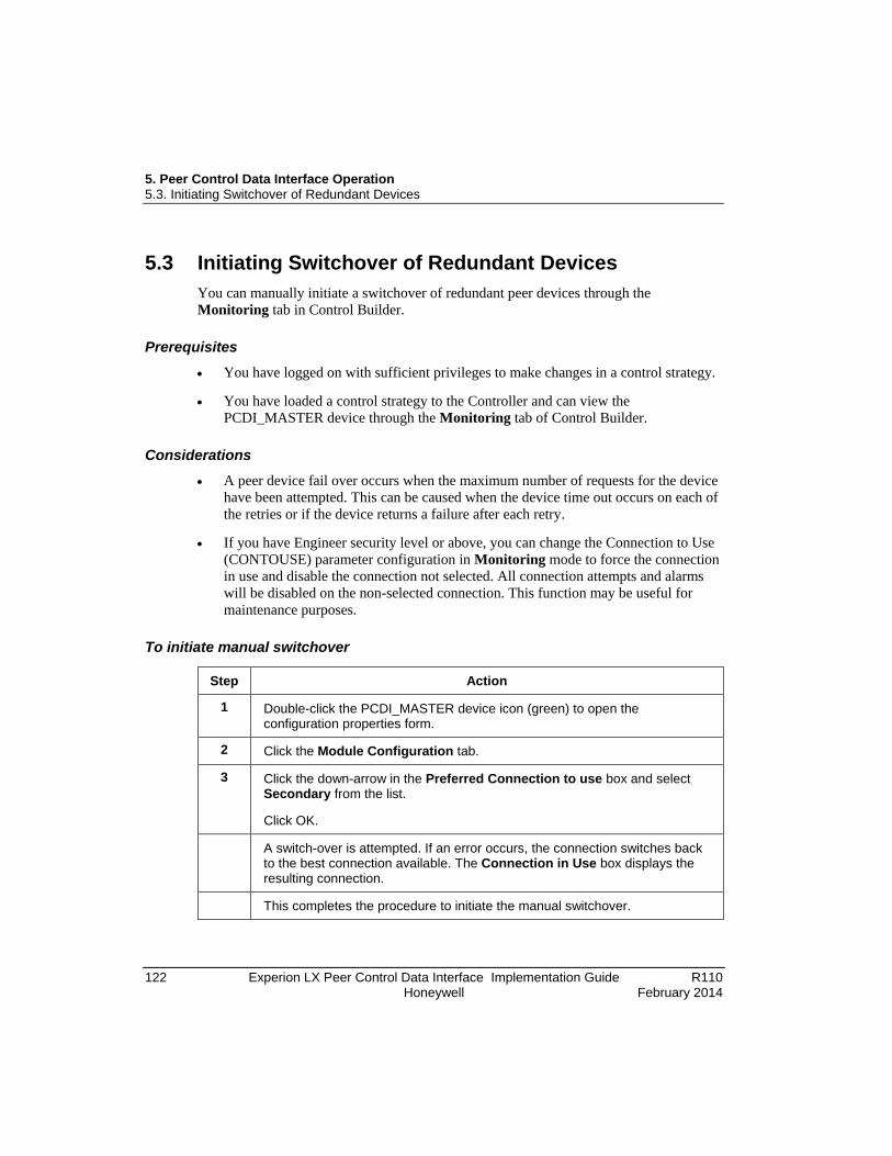
5. Peer Control Data Interface Operation 5.3. Initiating Switchover of Redundant Devices
122 Experion LX Peer Control Data Interface Implementation Guide R110 Honeywell February 2014
5.3 Initiating Switchover of Redundant Devices You can manually initiate a switchover of redundant peer devices through the Monitoring tab in Control Builder.
Prerequisites • You have logged on with sufficient privileges to make changes in a control strategy.
• You have loaded a control strategy to the Controller and can view the PCDI_MASTER device through the Monitoring tab of Control Builder.
Considerations • A peer device fail over occurs when the maximum number of requests for the device
have been attempted. This can be caused when the device time out occurs on each of the retries or if the device returns a failure after each retry.
• If you have Engineer security level or above, you can change the Connection to Use (CONTOUSE) parameter configuration in Monitoring mode to force the connection in use and disable the connection not selected. All connection attempts and alarms will be disabled on the non-selected connection. This function may be useful for maintenance purposes.
To initiate manual switchover
Step Action
1 Double-click the PCDI_MASTER device icon (green) to open the configuration properties form.
2 Click the Module Configuration tab.
3 Click the down-arrow in the Preferred Connection to use box and select Secondary from the list.
Click OK.
A switch-over is attempted. If an error occurs, the connection switches back to the best connection available. The Connection in Use box displays the resulting connection.
This completes the procedure to initiate the manual switchover.

5. Peer Control Data Interface Operation 5.4. Checking License Details
R110 Experion LX Peer Control Data Interface Implementation Guide 123 February 2014 Honeywell
5.4 Checking License Details Refer to the Control Hardware Planning Guide for more information about viewing application licenses and features.
5.5 Response to C300 RAM Retention Restart During a C300 RAM retention restart (RRR), all block request states are scanned and any non-pending or completed requests are set to error condition to force retransmission in the first block execution cycle. Request state will be available in battery backed PCI RAM. If the pending requests are not received (missed) due to excessive restart time or because they were sent while the node was unavailable, the requests are retransmitted and if they have reached the maximum retry count, they will timeout.
5.6 PCDI Support for Checkpoint Save/Restore functions The Checkpoint function in Control Builder allows you to save and restore operation and configure the associated data with a controller. The primary purpose of Checkpoint's save and restore functions are to provide the operator with the capability to bring a failed controller back to an operational condition as soon as possible. There are other ancillary scheduling, archiving and rebuilding functions provided by Checkpoint. Refer to the Checkpoint Reference section in the Control Building User's Guide for more information about the checkpoint function.
While the operation and configuration data associated with PCDI supports the standard Experion LX checkpoint save/restore functions, note the following exceptions for the given PCDI parameter data.
• A checkpoint save operation does not save any run-time values for the following PCDI related parameters. It only saves the configuration values for these parameters.
PCDI Parameter PCDI Parameter PCDI Parameter
DEFTIMOUT LOOPTYPE UIDLOOPMODE
MAXPENDREQ LOOPADDR UIDLOOPTYPE
MAXUIDREQ LOOPDATA UIDLOOPADDR
REQRTRY LOOPDATACHG UIDLOOPDATA
MSGDELAY PREFERREDCONN UIDLOOPDATACHG
LOOPRATE TIMOUT

5. Peer Control Data Interface Operation 5.6. PCDI Support for Checkpoint Save/Restore functions
124 Experion LX Peer Control Data Interface Implementation Guide R110 Honeywell February 2014
LOOPMODE UIDLOOPRATE
• A checkpoint save operation does not save a parameter that is not exposed during configuration even if a run-time configuration change exposes the parameter. For example, when LOOPTYPE is configured as Diag Register, both LOOPADDR and LOOPDATA are not available/exposed. If the LOOPTYPE configuration is changed to Coil during run-time, both LOOPADDR and LOOPDATA are available/exposed; but they will not be saved in the checkpoint file.

5. Peer Control Data Interface Operation 5.6. PCDI Support for Checkpoint Save/Restore functions
R110 Experion LX Peer Control Data Interface Implementation Guide 125 February 2014 Honeywell


R110 Experion LX Peer Control Data Interface Implementation Guide 127 February 2014 Honeywell
6. Peer Control Data Interface Maintenance
Periodic Checks The following table identifies checks that you should make periodically (every 3 to 6 months) to keep the peer control data interface in good working condition.
Check . . . Possible Corrective Action . . .
That all connections are secure. Secure connections, as needed.
That cable insulation is not worn or cracked.
Replace cables, as required.
That third-party equipment is being maintained.
Follow vendor maintenance recommendations.

6. Peer Control Data Interface Maintenance 5.6. PCDI Support for Checkpoint Save/Restore functions
128 Experion LX Peer Control Data Interface Implementation Guide R110 Honeywell February 2014

R110 Experion LX Peer Control Data Interface Implementation Guide 129 February 2014 Honeywell
7. Peer Control Data Interface Troubleshooting
7.1 Isolating Problems This section provides details about some general data regarding fault classifications and initial checks that may help you isolate the cause of a problem.
If you have observed a specific symptom and/or identified an error code, go to the Fixing Common Problems section to see if you can find a matching topic.
7.2 Fault Classifications The following table lists some possible ways for classifying faults along with some identifying characteristics.

7. Peer Control Data Interface Troubleshooting 7.3. Initial Checks
130 Experion LX Peer Control Data Interface Implementation Guide R110 Honeywell February 2014
Hard Failure Failure detected by hardware; operation cannot continue. If the fault does not prevent software processing the problem, the affected node will be rebooted under software control into the FAIL State.
• If failure occurs on Primary node, it triggers a switchover to synchronized Secondary node.
• If failure occurs on Secondary node, it results in loss of synchronization and reduced availability until the problem is resolved.
• If failure occurs on non-redundant node, it results in loss of control and loss of view.
Severe Failure Failure detected by software; operation cannot continue. The affected node will be rebooted under software control into the FAIL State.
The failure scenarios are as listed in the row above for the Hard Failure.
Soft Failure Failure detected by software; operation continues with full control and full view. Soft failures are alarmed to the operator. FTE will be monitored by the FTE System Management Tool.
• If failure occurs on Primary node, it does not trigger a switchover to synchronized Secondary node.
• If failure occurs on Secondary node, it does not result in loss of synchronization.
• If failure occurs on non-redundant node, it does not result in loss of control and loss of view.
Installation/Startup Failure
Detected by software. Node may not become operational.
• This failure does not apply to synchronized Primary node, since installation and startup must be successful to reach synchronized Primary state.
• If failure occurs on Secondary node, it results in the inability to complete the initial synchronization and to view the node on the network.
• If failure occurs on non-redundant node, it results in the inability to commence control and to view the node on the network.
Communication Communication errors between peer nodes and/or I/O devices, including Fault Tolerant Ethernet Bridge (FTEB), do not cause any node state change.
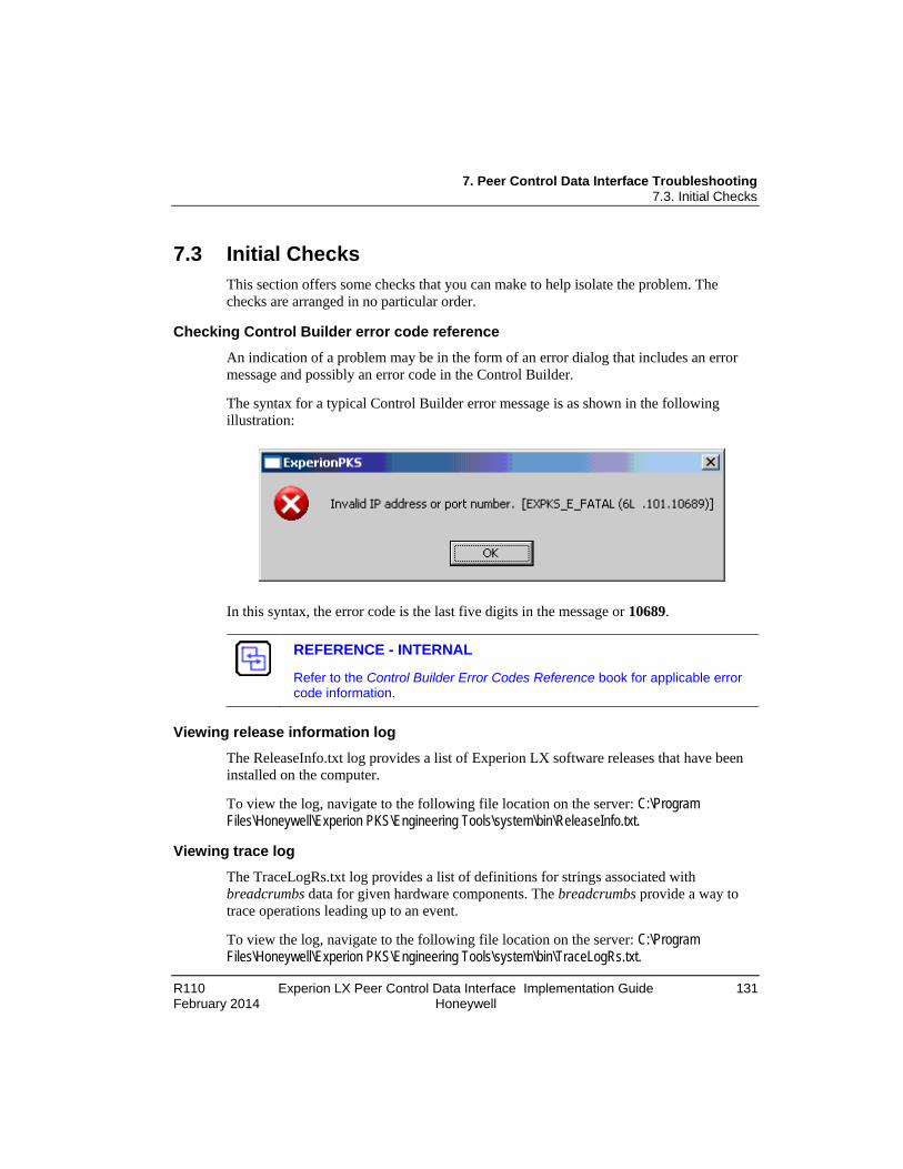
7. Peer Control Data Interface Troubleshooting 7.3. Initial Checks
R110 Experion LX Peer Control Data Interface Implementation Guide 131 February 2014 Honeywell
7.3 Initial Checks This section offers some checks that you can make to help isolate the problem. The checks are arranged in no particular order.
Checking Control Builder error code reference An indication of a problem may be in the form of an error dialog that includes an error message and possibly an error code in the Control Builder.
The syntax for a typical Control Builder error message is as shown in the following illustration:
In this syntax, the error code is the last five digits in the message or 10689.
REFERENCE - INTERNAL
Refer to the Control Builder Error Codes Reference book for applicable error code information.
Viewing release information log
The ReleaseInfo.txt log provides a list of Experion LX software releases that have been installed on the computer.
To view the log, navigate to the following file location on the server: C:\Program Files\Honeywell\Experion PKS\Engineering Tools\system\bin\ReleaseInfo.txt.
Viewing trace log The TraceLogRs.txt log provides a list of definitions for strings associated with breadcrumbs data for given hardware components. The breadcrumbs provide a way to trace operations leading up to an event.
To view the log, navigate to the following file location on the server: C:\Program Files\Honeywell\Experion PKS\Engineering Tools\system\bin\TraceLogRs.txt.

7. Peer Control Data Interface Troubleshooting 7.4. Fixing Common Problems
132 Experion LX Peer Control Data Interface Implementation Guide R110 Honeywell February 2014
Checking version and revision log The ver_rev.txt log provides a list of components by model number with software version/revision along with compatible Experion LX software release(s).
To check the log, navigate to the following file location on the server: C:\Program Files\Honeywell\Experion PKS\Engineering Tools\system\bin\ver_rev.txt.
Checking server point build log The SvrPtBld.txt log provides list of process (CB) points built in the server database.
To check the log, navigate to the following file location on the server: C:\Program Files\Honeywell\Experion PKS\Engineering Tools\temp\SvrPtBld.txt.
Checking server point build error log The svrptblderr.txt log provides list of errors associated with process (CB) points built in the server database.
To check the log, navigate to the following file location on the server: C:\Program Files\Honeywell\Experion PKS\Engineering Tools\temp\svrptblderr.txt.
Checking error log The Errlog_n.txt log provides a running list of Control Builder detected errors in chronological order. The n represents any number that is assigned to the most recent log. To check the log, choose View>Error Log in the Control Builder.
7.4 Fixing Common Problems This section identifies some common problems and describes how you might fix them.
Loss of power The power supply has failed or the main power source has been shut down or is experiencing a brownout or blackout condition.
Diagnostic Check In the Monitoring tab, the PCDI_MASTER device icon turns red.
Cause Main power source has been disconnected or shut down either manually or temporarily by brownout or blackout condition.
Solution Re-connect the main power source or turn it On or wait for temporary brownout or blackout condition to pass.

7. Peer Control Data Interface Troubleshooting 7.4. Fixing Common Problems
R110 Experion LX Peer Control Data Interface Implementation Guide 133 February 2014 Honeywell
Loss of communications No device data is being processed.
Diagnostic Check In the Monitoring tab, the PCDI_MASTER device icon turns red.
In Station Event Summary, event error is logged.
Cause 1 Broken or disconnected cable.
Solution Repair broken cable or connect cable, as applicable.
Cause 2 Intermittent communications timeout in device.
Solution For redundant devices, switchover to secondary device.
Try cycling power to the device. Replace the device, if fault persists.
Initiate a MODBUS loopback test on each end device to check if device can be reached.

7. Peer Control Data Interface Troubleshooting 7.5. Getting Further Assistance
134 Experion LX Peer Control Data Interface Implementation Guide R110 Honeywell February 2014
7.5 Getting Further Assistance Guidelines for requesting support
If you cannot resolve a problem using this guide, you can request support from your Honeywell Solution Support Center.
When requesting support, supply as many relevant details as possible, including:
• Short summary of the problem.
• Product Name and release.
• Recent changes, such as upgrades/service packs, to Experion LX software, Windows or other applications.
• Subsystem and its version/build, if the problem relates to a particular subsystem, such as Station or Quick Builder. If the problem relates to Display Builder, specify whether it is HMIWeb Display Builder (for HMIWeb displays) or Display Builder (for DSP displays).
• Operating system, variant and service pack, for example "Windows 2000 Server, SP5".
• Instructions on how to reproduce the problem. If the problem is reproducible, supply step-by-step instructions - the more detailed the steps the better.
• Diagnostic package which contains any relevant logs.


Honeywell Process Solutions 1860 W. Rose Garden Lane Phoenix, AZ 85027 USA