Pediatric Ankle Joint (13mm Systems) PRODUCT MANUAL · Pediatric Ankle Joint (13mm Systems) PRODUCT...
20
Pediatric Ankle Joint (13mm Systems) PRODUCT MANUAL Patent #10,500,081 ©2020 Becker Orthopedic Appliance Co. All rights reserved. Revision 07/01/20 Acorn Regulatory Consultancy Services Limited Knockmorris Cahir Co. Tipperary Ireland, Postcode: E21 R766 P 012 4626 8456 F 012 4626 8648
Transcript of Pediatric Ankle Joint (13mm Systems) PRODUCT MANUAL · Pediatric Ankle Joint (13mm Systems) PRODUCT...
Pediatric Ankle Joint(13mm Systems)
PRODUCT MANUAL
Patent #10,500,081©2020 Becker Orthopedic Appliance Co.All rights reserved.Revision 07/01/20
Acorn Regulatory Consultancy Services Limited Knockmorris Cahir Co. Tipperary Ireland, Postcode: E21 R766
P 012 4626 8456 F 012 4626 8648

®
Pediatric Ankle Joint
2.
The Pediatric Triple Action ankle joint offers unique features and exceptional performance for the orthotic treatment of complex and combined
biomechanical deficits in Cerebral Palsy, Spina Bifida and other pathologic neuromuscular conditions. Triple Action® has been shown to systematically influence the gait cycle in biomechanical studies.
The defining feature of Triple Action orthotics is the independent action of plantarflexion resistance, dorsiflexion resistance and alignment. The component’s high stiffness, long-life springs and alignment feature can be tuned to optimize the phases of the gait cycle. This adjustability gives the clinician an effective tool to help balance support for the ankle and knee.
The Triple Action® ankle joint delivers features for all stages of pediatric orthotic management; as a static progressive orthotic adjunct to Botox® treatment, post-surgical immobilization following heel cord release or mobilization of the spastic ankle for active ambulation.
TRIPLE ACTION® DIFFERENCE
®
Pediatric Ankle Joint(13mm Systems)
®
Pediatric Ankle Joint
1.
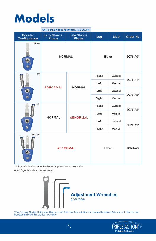
Models
Adjustment Wrenches (included)
*Only available direct from Becker Orthopedic in some countries
Booster Configuration
Early Stance Phase
Late Stance Phase Leg Side Order No.
NORMAL
NORMAL
Either
ABNORMAL
3C76-A0*
NORMAL ABNORMAL
ABNORMAL
Right
Left
Lateral
Medial
Right
Left Lateral
Medial
Right
Left
Lateral
Medial
3C76-A1*
Right
Left Lateral
Medial
3C76-A3
3C76-A2*
3C76-A2*
3C76-A1*
Either
*The Booster Spring Unit cannot be removed from the Triple Action component housing. Doing so will destroy the Booster and void the product warranty.
None
PF
DF
PF & DF
Note: Right lateral component shown
®
Pediatric Ankle Joint
2.
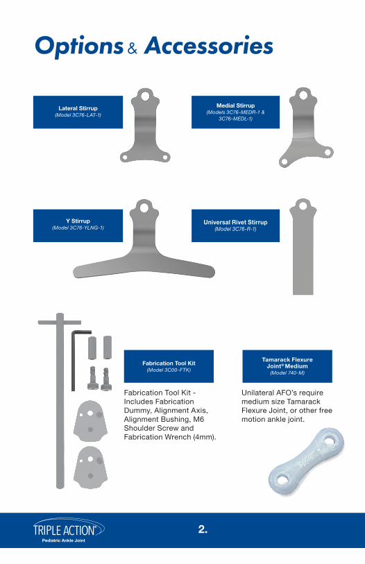
Options & Accessories
Fabrication Tool Kit - Includes Fabrication Dummy, Alignment Axis, Alignment Bushing, M6 Shoulder Screw and Fabrication Wrench (4mm).
Fabrication Tool Kit(Model 3C00-FTK)
Lateral Stirrup(Model 3C76-LAT-1)
Medial Stirrup(Models 3C76-MEDR-1 &
3C76-MEDL-1)
Y Stirrup(Model 3C76-YLNG-1)
Universal Rivet Stirrup(Model 3C76-R-1)
Tamarack Flexure Joint® Medium
(Model 740-M)
Unilateral AFO’s require medium size Tamarack Flexure Joint, or other free motion ankle joint.
®
Pediatric Ankle Joint
3.
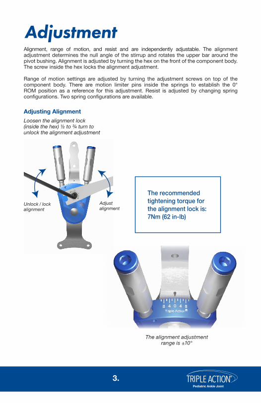
Alignment, range of motion, and resist and are independently adjustable. The alignment adjustment determines the null angle of the stirrup and rotates the upper bar around the pivot bushing. Alignment is adjusted by turning the hex on the front of the component body. The screw inside the hex locks the alignment adjustment.
Range of motion settings are adjusted by turning the adjustment screws on top of the component body. There are motion limiter pins inside the springs to establish the 0° ROM position as a reference for this adjustment. Resist is adjusted by changing spring configurations. Two spring configurations are available.
Loosen the alignment lock (inside the hex) ½ to ¾ turn to unlock the alignment adjustment
The alignment adjustment range is ±10°
Adjusting Alignment
Adjustment
The recommended tightening torque for the alignment lock is: 7Nm (62 in-lb)
Unlock / lock alignment
Adjustalignment

®
Pediatric Ankle Joint
4.
Motion Limiter Pin
3
4
5
1. Remove the adjustment screw, resist spring and motion limiter pin from the channel
2. Do not remove the ball bearing
3. Grease the motion limiter pin
4. Insert the motion limiter pin into the spring
5. Wipe excess grease from the outside of the spring
6. Install the spring with the motion limiter pin into the channel and tighten the adjustment screw until resistance is felt.
7. Adjust range of motion as necessary
Spring Installation
1
6
7
*The recommended tightening torque for the Booster cap is: 5 Nm (44in-lb)
Booster Cap*
®
Pediatric Ankle Joint
5.
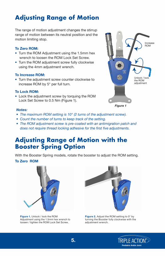
The range of motion adjustment changes the stirrup range of motion between its neutral position and the motion limiting stop.
To Zero ROM:• Turn the ROM Adjustment using the 1.5mm hex wrench to loosen the ROM Lock Set Screw.• Turn the ROM adjustment screw fully clockwise
using the 4mm adjustment wrench.
To Increase ROM:• Turn the adjustment screw counter clockwise to
increase ROM by 5° per full turn.
To Lock ROM:• Lock the adjustment screw by torquing the ROM
Lock Set Screw to 0.5 Nm (Figure 1).
Notes:• The maximum ROM setting is 10° (2 turns of the adjustment screw).• Count the number of turns to keep track of the setting.• The ROM adjustment screw is pre-coated with an antimigration patch and
does not require thread locking adhesive for the first five adjustments.
With the Booster Spring models, rotate the booster to adjust the ROM setting.To Zero ROM
Adjusting Range of Motion with the Booster Spring Option
Adjusting Range of Motion
Figure 1. Unlock / lock the ROM Adjustment using the 1.5mm hex wrench to loosen / tighten the ROM Lock Set Screw.
Figure 2. Adjust the ROM setting to 0° by turning the Booster fully clockwise with the adjustment wrench.
Unlock / lock the ROM adjustment
Figure 1
Increase ROM

®
Pediatric Ankle Joint
6.
For best results, Triple Action AFO designs must be rigid. AFOs that are too flexible will decrease the systematic influence of the Triple Action ankle joint on gait. Rigid thermoplastic polypropylene materials in 4mm (5/32 inches) thickness are recommended for Triple Action AFO fabrication. Ribs or stiffeners placed at the distal tibial section may also be used to stiffen the orthotic structure. It is recommended that anterior (ventral) tibial shell with full footplate AFO designs be used where dorsiflexion resist is greater than plantarflexion resist in order to manage knee flexion. Ankle foot orthoses may use one or two Triple Action components depending on patient weight and spasticity. However, if a single Triple Action is used, it is necessary to pair the Triple Action with a free motion companion joint. Becker Orthopedic recommends the medium size Tamarack Flexure Joint (Model 740-M or Model 740-M-BLK) as a companion joint in single Triple Action applications.
One Triple Action® or Two?The decision whether to use one or two Triple Action ankle joints should considerPatient weight: 25 kg (55 lb) to 50 kg (110 lb)Spasticity: Low, Moderate, HighCalf circumference: 20 cm (8 in) to 40 cm (16 in)Important: Two Triple Action components are recommended for Post-Op applications
Orthotic Design Considerations
*Requires Companion Joint
Important: Unilateral AFOs require medium size Tamarack Flexure Joint® , or other free motion ankle joint.
4mm (5/32”) PolypropyleneUnilateral*
Thermoplastic
Bilateral4mm (5/32”) Polypropylene
Fabrication Options

®
Pediatric Ankle Joint
7.
The upper bar and stirrup must be removed from the component body and attached to the Fabrication Dummy for fabrication.
To remove the bar and stirrup from the component body
1. Remove the Pivot Bushing E-Clip using the combination wrench
2. Remove the Pivot Bushing
3. Slide the upper bar toward the top of the component body and remove
4. Remove the stirrup
Disassembly for Fabrication
1
3
2
4
1
If the Pivot Bushing is difficult to remove from the component body, slightly loosen the adjustment screws.
Prior to re-assembly, grease the pivot bushing, upper bar slot and stirrup head.
Apply threadlocker to bar attachment screws prior to final assembly.
Use the combination wrench to remove the Pivot Bushing E-Clip
Disassembling the Pediatric Triple Action®
®
Pediatric Ankle Joint
8.
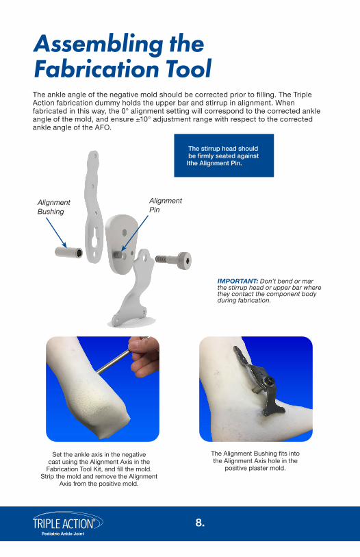
The ankle angle of the negative mold should be corrected prior to filling. The Triple Action fabrication dummy holds the upper bar and stirrup in alignment. When fabricated in this way, the 0° alignment setting will correspond to the corrected ankle angle of the mold, and ensure ±10° adjustment range with respect to the corrected ankle angle of the AFO.
AlignmentBushing
AlignmentPin
IMPORTANT: Don’t bend or mar the stirrup head or upper bar where they contact the component body during fabrication.
Assembling the Fabrication Tool
Set the ankle axis in the negative cast using the Alignment Axis in the
Fabrication Tool Kit, and fill the mold. Strip the mold and remove the Alignment
Axis from the positive mold.
The Alignment Bushing fits into the Alignment Axis hole in the
positive plaster mold.
I
The stirrup head should be firmly seated against the Alignment Pin.
®
Pediatric Ankle Joint
9.
Through biomechanical research, Becker Orthopedic has developed an evidence-based Systematic Tuning Procedure to help simplify application of the Triple Action® ankle joint. This procedure is intended as a starting point to help you more quickly arrive at optimal component settings using Observational Gait Analysis.
Tuning Procedure
1. Bench Adjustment2. Static Alignment3. Swing Phase Alignment4. Stance Phase Adjustment
Spring Selection
Before performing Bench Adjustment, the desired Triple Action springs must be installed. Refer to “Spring Installation” for additional information on spring installation.
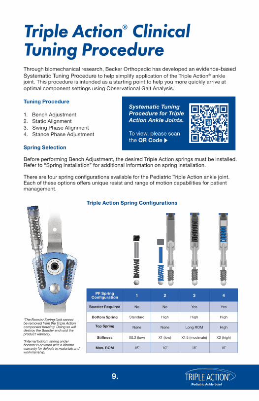
There are four spring configurations available for the Pediatric Triple Action ankle joint. Each of these options offers unique resist and range of motion capabilities for patient management.
Triple Action® Clinical Tuning Procedure
Triple Action Spring Configurations
PF Spring Configuration 1 2 3 4
Booster Required No No Yes Yes
Bottom Spring Standard High High High
Top Spring None None Long ROM High
Stiffness X0.2 (low) X1 (low) X1.5 (moderate) X2 (high)
Max. ROM 15˚ 10˚ 18˚ 10˚
*The Booster Spring Unit cannot be removed from the Triple Action component housing. Doing so will destroy the Booster and void the product warranty.
*Internal bottom spring under booster is covered with a lifetime warranty for defects in materials and workmanship.
Systematic Tuning Procedure for Triple Action Ankle Joints.
To view, please scan the QR Code

®
Pediatric Ankle Joint
10.
*Gait Type from “Classification of gait patterns in spastic hemiplegia and spastic diplegia: a basis for a management algorithm”. Rodda et al. 2001.
Spring Selection (Continued)The Standard and High Resist Springs are suitable for the management of mildbiomechanical deficits in larger patients or smaller patients with more severe deficits. To expand applications to heavier patients with higher spasticity, the Booster Spring option may be installed or two components may be used.
Spring Selection (Continued)
The Standard and High Resist Springs are suitable for the management of mildbiomechanical deficits in larger patients or smaller patients with more severe deficits. To expand applications to heavier patients with higher spasticity, the Booster Spring SRA* option may be installed or two components may be used. The SRA can be installed in either or both the plantarflexion and dorsiflexion resist channel(s).
Gait Type* Pattern Orthotic Design
Mild to Moderate
Moderate to Severe
Gait Type 1: Hemiparesis with drop foot in swing phase secondary to dorsiflexion insufficiency. No significant triceps surae contracture.
Posterior (dorsal) tibial shell. Sulcus length footplate.
Gait Type 2: Hemiparesis with dropfoot and true equinus secondary to triceps surae contracture, with or without genu recurvatum.
Posterior (dorsal) tibial shell. Sulcus length footplate.
Gait Type 3: Hemiparesis with true equinus. Jump gait with contracture or spasticity of gastrosoleus. Spastic co-contraction of quadriceps and hamstrings.
Anterior (ventral) tibial shell. Full length footplate.
Gait Type 4: Hemiparesis gait type 3 plus hip flexor/adductor spasticity.
Anterior (ventral) tibial shell. Full length footplate.
Crouch Gait: Diplegia with excessive dorsiflexion, knee and hip flexion.
Anterior (ventral) tibial shell. Full length footplate.

®
Pediatric Ankle Joint
11.
Bench Adjustment
Prior to fitting the orthosis, bench adjust the components as follows:1. Lock plantarflexion (PF) ROM at 0°2. Lock dorsiflexion (DF) ROM at 0°3. Set the alignment to 0˚
Lock both ROM settings by turning the adjustment screws fully clockwise. Refer to “Adjusting Range
of Motion” for additional information.
Triple Action® Clinical Tuning Procedure
Adjust the alignment setting to 0°. Refer to “Adjusting Alignment” for additional information.

®
Pediatric Ankle Joint
12.
Static Alignment (PF and DF ROM at 0°)Don the orthosis and shoes to the patient and perform static alignment with the patient standing. Adjust the ankle angle with the ROM settings locked at 0° to tune the shank to vertical angle, and move the weight line over the midfoot. The knee should be slightly flexed. A typical starting point for the shank to vertical angle is 11°. This is measured at the tibial crest with the orthosis and shoe donned. Optimize the patient’s sense of standing balance and stability. If there is insufficient dorsiflexion ROM to make the adjustment due to a gastrosoleus contracture, a lift may be required under the heel of the AFO to incline the shank.
Toe Clearance (left) and Foot to Floor Angle (right)
Swing Phase Alignment (PF and DF ROM at 0°)With the ROM settings still locked at 0°, use the alignment setting to adjust toeclearance in mid swing and foot position at initial contact. Observe the foot to floorangle while making this adjustment. Note that increasing dorsiflexion alignment mayreduce knee extension at terminal swing if there is gastrocnemius tone or contracture. Also observe step length symmetry while making this adjustment.

®
Pediatric Ankle Joint
13.
Early Stance Phase Adjustment(DF ROM at 0°)Adjust plantarflexion ROM to activate the anklein 1st rocker and early stance to stabilize the knee.Begin by increasing the plantarflexion (PF) ROMsetting by 1 to 2-turns (5 to 10°) of the adjustmentscrew.
• If toe clearance or foot to floor angle decreases Decrease the PF ROM.
• If knee hyperextension in early stance increases Decrease the PF ROM.
• If the knee flexes excessively in 1st rocker Increase the PF ROM.
Late Stance Phase AdjustmentAdjust dorsiflexion ROM to activate the anklein 2nd rocker and late stance to stabilize theknee. Begin by increasing the dorsiflexion (DF) ROM by 1 to 2-turns (5 to 10°) of the adjustment screw.
• If the knee flexes excessively after midstance Decrease the
DF ROM.• If the knee hyperextends at the end
of stance phase Increase the DF ROM.

®
Pediatric Ankle Joint
14.
Triple Action Components
Top View Small Parts
Front View Side View
3B
5
7 (BLUE)
8 (BLUE)
12
13
Accessories
15 16
3A 3 2
4
5
14
1C
7
1B
1
9
10
11
6
7
8
26
23 24 TG TL22 25

®
Pediatric Ankle Joint
15.
Triple Action Part NumbersReference # Description
Booster Spring Base and Pin Assembly
Booster Cap
Pivot Bushing
Cam Bushing
Cam Bushing Screw
Cam Bushing Locking Jaw
Upper Bar
HD Side Mount Ext. Retaining Ring (1/4”)
1/4” Ball Bearing
High Torque Spring
High Torque Pin 3mm x 10mm
Set Screw M8 x 1 x 8mm Flat Point
Standard Torque Spring
Standard Torque Pin 1/8 x 7/16
Attachment Screw 6mm
Attachment Screw 8mm
Spring Spacer
Upper Bar Pelite Pad - 3mm
Upper Bar Shearban® Patch
Combination Wrench
4mm Hex Wrench
2.5mm Hex Wrench
1.5mm Hex Wrench
Long Rom Spring
Teflon Grease
Thread Lock
1B
1C
2
3
3A
3B
4
5
6
7
8
9
10
11
12
13
14
15
16
22
23
24
25
26
TG
TL
Note:• To order parts, please specify the original order number, right or left, medial or lateral,
followed by the part number desired.

®
Pediatric Ankle Joint
16.
Notes

®
Pediatric Ankle Joint
17.
Notes

Pediatric Ankle Joint(13mm Systems)
®
Patent #10,500,081©2020 Becker Orthopedic Appliance Co.All rights reserved.Revision 07/01/20
Acorn Regulatory Consultancy Services Limited Knockmorris Cahir Co. Tipperary Ireland, Postcode: E21 R766
P 012 4626 8456 F 012 4626 8648