
BokSmart - Lower Limb Injury Prevention Practical Guidelines

IRCOBI Conference – Graz (Austria) September 2004 193
PEDESTRIAN LOWER LIMB INJURY CRITERIA EVALUATION
A FINITE ELEMENT APPROACH
P.J. Arnoux1, D. Cesari
2, M. Behr
1, L. Thollon
3, C. Brunet
1.
1 Laboratoire de Biomécanique Appliquée, UMRT 24 Faculté de Médecine - INRETS, Université
de la Méditerranée, Marseille, France. 2 INRETS Scientific direction- Lyon Bron
3MECALOG - Safety Business Unit, Paris, France.
Abstract Improvements of pedestrian leg protection should focus on knee ligaments damage and bone failure minimization. One method is to study injury mechanisms by focusing on the relationships between ultimate lateral bending and shearing at the knee level and potential ligament damage. A specific analysis of the LLMS model of the lower limb was used in pure lateral shearing and bending impact tests. The ultimate knee lateral bending and shearing for potential failure of ligaments (posterior cruciate, medial collateral, cruciates and tibial collateral) was evaluated to be close to 16° and 15 mm respectively.
Key words
BIOMECHANICS, FINITE ELEMENT METHOD, INJURY PROBABILITY, PEDESTRIANS, LEGS SAFETY CONCERNS have been taking a large and increasing place in the car design process. The assessment of car crashworthiness is more and more related to the evaluation of injury risk for car occupants, pedestrians and cyclists, and the development of advanced safety systems. At a research level, the first point of interest is injury mechanisms. This is why both experimental and numerical approaches have been used to investigate the human behaviour and tolerance under impacts and to develop realistic human body models (Lizee & al. 1998, Atkinson & al. 1998, Thollon & al. 2001, Arnoux & al. 2001, Beillas & al 2001, Behr & al. 2001, Nyquist & al. 1985, Crandall & al. 1996, Parenteau 1996, J. Kajzer & al. 1993). IN THE FIELD OF PEDESTRIAN INJURY BIOMECHANICS, lower limbs are highly loaded during crash situations (AIS from 2 to 6) with joints damages and bones failures (IHRA 2000, Stutts 1999). From an experimental point of view, during a pedestrian impact, knee injuries could be produced by a combination of lateral shearing and bending of the knee (Kajzer 1990, Kajzer 1993, Grzegorz 2001, Bose 2004). On cadaver full leg experiments, Kajzer (1990 & 1993) focused on impact forces and bending moments corridors. He showed that pure shearing induces collateral tibial and anterior cruciate ligament failure when a primarily bending mainly induces medial collateral ligament failure. More recently, Bose (2004) worked on 3-point bending tests on isolated knee joints in order to obtain a combination of shearing and bending effects, and confirmed injuries to medial collateral and anterior cruciate ligaments. It can be noted that knee injuries are not restricted to the injuries described above. Tibia fractures (especially with tibial eminence in contact with the intercondylar notch at impact), PCL injuries, fibula and femur fractures can also be observed. From all these studies, it appears that the main challenge for improving leg protection should focus on knee ligament damage and failure minimization. NUMERICAL SIMULATION, and more specifically finite element modelling, can be very helpful to complete injury mechanisms understanding, once the finite element model is validated

IRCOBI Conference – Graz (Austria) September 2004 194
through appropriated experimental tests. Many finite element models have been designed to study very specific points of the leg behaviour under crash situations. Some ankle-foot models focused on kinematics (M. Beaugonin & al. 1996, P. Beillas & al. 1999), others on material properties (M. Beaugonin & al. 1997, R. Tannous & al. 1996) or on an accurate description of the geometry (P. Beillas & al. 1999). Knee models were also developed for frontal impacts (S. Hayashi & al. 1996, P. Atkinson 1998) or pedestrians (J. Yang 1997, P. Schuster & al. 2000). Lastly, Bedewi (1996) included mathematical joints in order to control the kinematics of a full lower limb model. More recently, the LLMS model (lower limb model for safety,. Fig. 1), designed in collaboration between Mecalog and the Laboratory of Applied Biomechanics is an advanced finite element model of the whole lower limb (Beillas 2001, Arnoux 2001, 2002, 2003). This model was based on an accurate description of all anatomical parts of the lower limb and its validation was performed in various impact situations (isolated materials, sub-segments up to the whole model).
USUALLY, NUMERICAL MODEL VALIDATION compares responses obtained from simulations using the finite element model with experimental test results performed under the same impact conditions. One major interest in human modelling lies in the possibility of numerically recording specific parameters (strain, stress, pressures and kinematics) that could not be available during experiments. With this data, it becomes easier to show tissue kinematics and mechanical behaviour during the crash chronology and then, to postulate on potential injuries. For knee injuries on pedestrians, one way to define an injury risk criterion or an injury probability for knee soft tissues is to evaluate the ultimate lateral bending and shearing levels of the knee before damage, when the impact occurs. In order to investigate the corresponding injury mechanisms and then evaluate these ultimate levels, we have used the LLMS finite element model of the lower limb. This paper gives a general overview of the model, from geometry acquisition (based on RMI data) to the modelling choices and validation database. Then, a specific analysis of the model response (bone Von Mises stress levels, ligament global and local strain levels, knee rotation and shearing measurements) was performed. These numerical simulations are based on previous experimental work reported by Kajzer (1990 & 1993). It consists in lateral bending impact tests on an isolated lower limb (the impact being applied on the internal malleolus); then, a pure shearing impact test on an isolated lower limb was performed, the tibia being loaded simultaneously at its two extremities. As impact velocities in pedestrian is a gravity factor, this first test campaign was focused on extended velocities ranging from 2 to 10 m/s. MODEL DESIGN AND VALIDATION THE MODEL GEOMETRY was obtained on a 50th percentile human male volunteer. Measurements were performed in the sagittal plane from the hip to the toe region (the leg being extended). The scanning step was of 1 mm in joint regions and ranged from 5 mm to 10 mm in other parts. Moreover, longitudinal and frontal scans taken between the femur and tibia were used in order to determine the geometry of the menisci, to check hip connections in the pelvis area and more generally, to check scans alignments. Altogether, more than 600 images (approximately 150 CT and 460 MRI images) were available for the reconstruction of the model geometry. Once MRI measurements were achieved, each anatomical component was identified by anatomists on each section. The contours were then computed to create a 3D reconstruction of the lower limb. It was then possible to mesh all parts of the model using shells, membranes, bricks and other solid elements depending on the parts modelled. The characteristic lengths were defined to settle an initial time step ranging from 0.8 to 1µs. The model includes approximately 25,000 elements for compact and trabecular bones, knee cartilage, menisci, knee ligaments, tendons and skin. Muscle description was simplified by gathering muscles in one same part called flesh (Fig. 1).

IRCOBI Conference – Graz (Austria) September 2004 195
Fig. 1 –LLMS global overview
FROM MESH TO MODEL DEFINITION: Because of the cortical bones thickness and the time step constraint, compact bones were modelled using shell elements. The inner and outer cortical surfaces were used to compute a mid-surface and to estimate the bone local thickness at each section. The bones were divided in several geometrical parts in order to take bone thickness and density distribution into account (Fig. 2).
Fig. 2 - Example of thickness distribution along tibia
The spongious bone of femur, patella, tibia, fibula, talus and calcaneus were meshed with solid elements. Solid elements and their surrounding shell meshes were not coincident. They were connected in the model using tied contact interfaces. Compact and spongious bones were modelled with a Johnson Cook elasto-plastic material law. According to the literature data, different sets of parameters were used for each bone. Property variations on the same bone were included (considering differences and transitions between diaphysis, epiphysis or metaphysis). Foot bones (the 5 meta, the 5 phalanx, the 3 cunei and the cuboid) were set rigid. Mechanical parameters of bones (Burstein 1972, Goldstein 1987, Reilly 1975, McElhaney 1966) are summarized in table 1.
Compact Spongious
Young Modulus 9-15 Gpa 10-450 Mpa
Poisson ratio 0,3 0,3
Yield stress 80-120 Mpa 10 MPa
Ultimate stress 110-130 Mpa 15MPa
Hardening (param & coef) 100Mpa, 0,1 100Mpa, 0,1
Ultimate strain 2-3 % 3% Table 1: Summary of elastoplastic properties of bones
Foot and ankle ligaments were modelled using both elastic springs and viscoelastic shells. Each fibre includes several springs in order to describe the contact interface between ligaments and ligament external shape. The same method was used for the Achilles tendon. Knee soft tissues were modelled using bricks, shells and springs elements, depending on the dimensions of the corresponding tissue (Fig. 3). Cruciate ligaments and patellar tendon were described using both solids and shells in order to model membranes around the structure. Low stiffness springs were also added in order to compute deformations on the ligament using gauges with length ranging from 2 to 5 mm along the main axes of the ligament. Lateral ligaments and patellar wings were described using shell elements. Lastly, fibular-tibial ligaments and meniscus ligaments were described using springs.

IRCOBI Conference – Graz (Austria) September 2004 196
Fig. 3 - Medial, tibial, posterior, with capsula and opened view of the knee model. On the medial and
tibial views, the Medial and Lateral Collateral Ligaments (MCL and LCL), the medial and lateral
patellar wing (MPW and LPW), the medial and lateral meniscus patellar ligaments (MMP and LMP)
and the patellar tendon (PT) can be shown. On the posterior view, the two cruciate ligaments (ACL
and PCL) can be identified but also spring elements which modelled meniscus to femur and tibia
attachment. On the last view, distal femur and femur cartilage were removed in order to show
cartilage (Car) and meniscus (Men) components.
Ligaments and tendons of the knee were modelled with a generalized viscoelastic Kelvin Voigt material law or using elastic or viscoelastic spring elements based on literature data (Arnoux 2000, Johnson 1996, Noyes 1976, Attarian & al. 1985) (Table 2). Cartilage and menisci, which contribute to an accurate control and a good stability of the knee during its movement, were modelled using elastic solid elements (Fig. 3). This biphasic material (incompressible fluid within a fibrous structure) is highly strain rate dependent. The mechanical properties of such a structure are strongly linked to fluid exudation effects during loading. In this study, and due to the dynamic loading condition, we assumed, in a first approximation, the material being elastic (with a Young’s modulus of 20 MPa based on results of Yamada 1970, Repo 1977, & Atkinson 1998) in order to take the effects of strain rate into account. The result was extrapolated to the menisci (with a Young’s modulus of 200 MPa). Because of the lack of data on its dynamic properties, the capsula was described as an elastic material using shell elements (with a Young’s modulus of 20 MPa). Muscles were modelled in two separate ways. Firstly, the muscles action lines are described using springs elements (not active in the current model). Secondly, the muscles are modelled using solid elements in order to give a unique volumic shape to muscles and other aponevrotic tissues, and to describe damping properties during shocks. Except for foot phalanx joint described with a mathematical joint, all joints are defined using all anatomical components that contribute to joint kinematics and stability. Therefore, and in order to ensure interaction between tissues, several interfaces were defined: 1) Bones to bones, bones to ligaments and ligaments to ligaments. Cartilages to cartilage interfaces are used to describe joints or moving tissue contacts. They are modelled using self contact interfaces and edge to edge contact interfaces. 2) Tied contact interfaces, which ensure attachments (spongious bone to compact bone, flesh to bones), were modelled.
Ligaments & tendons
Young modulus 50-225 Mpa
Poisson ratio 0,3
Tengent Young modulus 48-155 Mpa
Tengent Poisson ratio 0,37
Viscosity in pure shear 6,6 Table 2: Summary of viscoelastic properties of ligaments
THE MODEL VALIDATION focused on mechanical properties of tissues, model ability to describe physiological movements, sub-segment behaviour under specific loading and finally, whole model testing (cf. validation database summary in Table 3). In order to give an overview of the model validation, only selected validation tests are reported below.
MCL
MPW
MMP
LCL
LPW
PT
PCL
ACL
Car
Men
IRCOBI Conference – Graz (Austria) September 2004 197
COMPUTED DATA Reference
ISOLATED MATERIAL
Anterior Cruciate traction Force, Displacement Arnoux 2000
Posterior Cruciate traction Force, Displacement Arnoux 2000
Medial collateral liagment traction Force,Displacement Arnoux 2000
Tibial collateral liagment traction Force, Displacement Arnoux 2000
Three point femur bending Force, Displacement Beillas 1999
Patellar tendon traction Stress, Strain Johnson 1996
SUB-SEGMENT TESTS
Knee joint Kinematic
Haut patellar impact on flexd knee Force, time Haut 1995
Hayashi patellar impact on flexed knee Force, time Hayashi 1996
Banglmeier Tibia impact on flexed knee Force, time Banglmeier 1999
Antero-posterior flexed knee loading Force, Displacement Viano 1978
Tibia Latero-medial 3 point bending Force, time Nyquist 1985
Tibia antero-posterior 3 point bending Force, time Nyquist 1985
Quasi-static lower leg compression Force, displacement Bennet 1990
Quasi-static tibo-fibular compression Force, displacement Beillas 2001
Ankle Inversion Moment, rotation Parenteau 1996
Ankle Eversion Moment, rotation Parenteau 1996
Ankle dorsiflexion Moment, rotation Parenteau 1996
WHOLE LLMS MODEL
Pedestrian LBA lateral bending Force, Rotation Kajzer 1993
Pedestrian LBA lateral shearing Force, time Kajzer 1990
Frontal Wayne sled test Force, time Beillas 2001 Table 3: Overview of model validation database
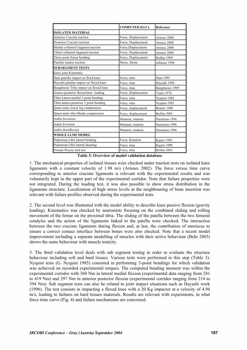
1. The mechanical properties of isolated tissues were checked under traction tests on isolated knee ligaments with a constant velocity of 1.98 m/s (Arnoux 2002). The force versus time curve corresponding to anterior cruciate ligaments is relevant with the experimental results and was voluntarily kept in the upper part of the experimental corridor. Note that failure properties were not integrated. During the loading test, it was also possible to show stress distribution in the ligaments structure. Localization of high stress levels in the neighbouring of bone insertion was relevant with failure profiles observed during the experimental tests. 2. The second level was illustrated with the model ability to describe knee passive flexion (gravity loading). Kinematics was checked by anatomists focusing on the combined sliding and rolling movement of the femur on the proximal tibia. The sliding of the patella between the two femoral condyles and the action of the ligaments linked to the patella were checked; The interaction between the two cruciate ligaments during flexion and, at last, the contribution of meniscus to ensure a correct contact interface between bones were also checked. Note that a recent model improvement including a separate modelling of muscles with their active behaviour (Behr 2003) shows the same behaviour with muscle tonicity. 3. The third validation level deals with sub segment testing in order to evaluate the structure behaviour including soft and hard tissues. Various tests were performed in this step (Table 3). Nyquist tests (G. Nyquist 1985) consisted in performing 3-point bendings for which validation was achieved on recorded experimental torques. The computed bending moment was within the experimental corridor with 360 Nm in lateral medial flexion (experimental data ranging from 241 to 419 Nm) and 297 Nm in anterior posterior flexion (experimental corridor ranging from 214 to 394 Nm). Sub segment tests can also be related to joint impact situations such as Hayashi work (1996). The test consists in impacting a flexed knee with a 20 Kg impactor at a velocity of 4.94 m/s, leading to failures on hard tissues materials. Results are relevant with experiments, in what force time curve (Fig. 4) and failure mechanisms are concerned.
IRCOBI Conference – Graz (Austria) September 2004 198
Fig. 4 - Force vs time force in case of Hayashi impact test
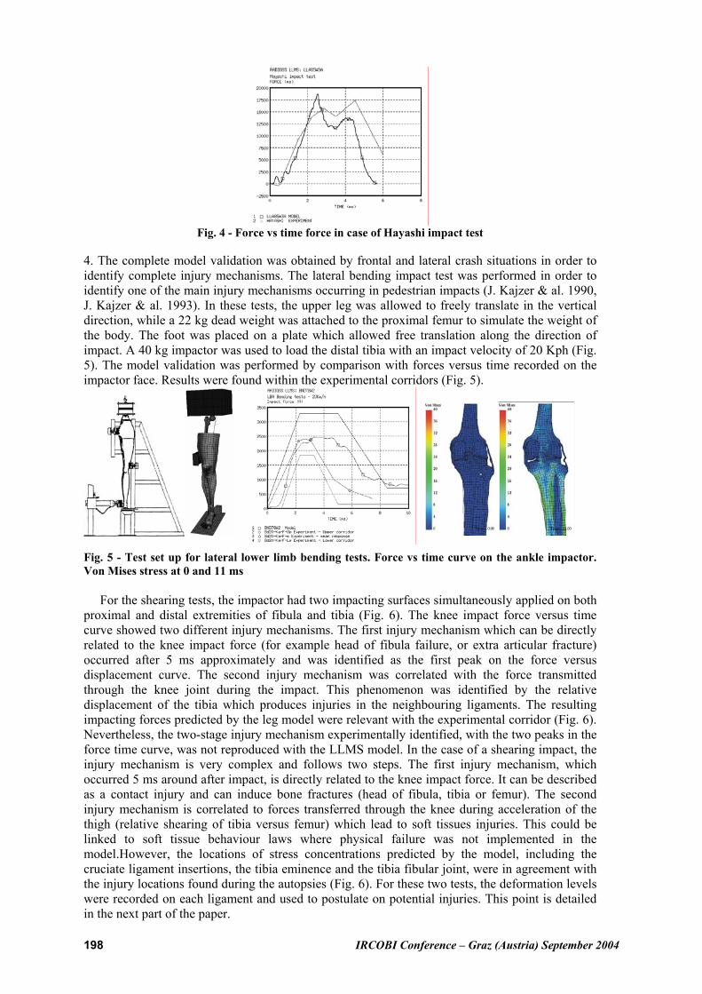
4. The complete model validation was obtained by frontal and lateral crash situations in order to identify complete injury mechanisms. The lateral bending impact test was performed in order to identify one of the main injury mechanisms occurring in pedestrian impacts (J. Kajzer & al. 1990, J. Kajzer & al. 1993). In these tests, the upper leg was allowed to freely translate in the vertical direction, while a 22 kg dead weight was attached to the proximal femur to simulate the weight of the body. The foot was placed on a plate which allowed free translation along the direction of impact. A 40 kg impactor was used to load the distal tibia with an impact velocity of 20 Kph (Fig. 5). The model validation was performed by comparison with forces versus time recorded on the impactor face. Results were found within the experimental corridors (Fig. 5).
Fig. 5 - Test set up for lateral lower limb bending tests. Force vs time curve on the ankle impactor.
Von Mises stress at 0 and 11 ms
For the shearing tests, the impactor had two impacting surfaces simultaneously applied on both proximal and distal extremities of fibula and tibia (Fig. 6). The knee impact force versus time curve showed two different injury mechanisms. The first injury mechanism which can be directly related to the knee impact force (for example head of fibula failure, or extra articular fracture) occurred after 5 ms approximately and was identified as the first peak on the force versus displacement curve. The second injury mechanism was correlated with the force transmitted through the knee joint during the impact. This phenomenon was identified by the relative displacement of the tibia which produces injuries in the neighbouring ligaments. The resulting impacting forces predicted by the leg model were relevant with the experimental corridor (Fig. 6). Nevertheless, the two-stage injury mechanism experimentally identified, with the two peaks in the force time curve, was not reproduced with the LLMS model. In the case of a shearing impact, the injury mechanism is very complex and follows two steps. The first injury mechanism, which occurred 5 ms around after impact, is directly related to the knee impact force. It can be described as a contact injury and can induce bone fractures (head of fibula, tibia or femur). The second injury mechanism is correlated to forces transferred through the knee during acceleration of the thigh (relative shearing of tibia versus femur) which lead to soft tissues injuries. This could be linked to soft tissue behaviour laws where physical failure was not implemented in the model.However, the locations of stress concentrations predicted by the model, including the cruciate ligament insertions, the tibia eminence and the tibia fibular joint, were in agreement with the injury locations found during the autopsies (Fig. 6). For these two tests, the deformation levels were recorded on each ligament and used to postulate on potential injuries. This point is detailed in the next part of the paper.

IRCOBI Conference – Graz (Austria) September 2004 199
� Fig. 6 - Shearing impact apparatus and model. Impact force versus time in shearing tests. Von Mises
stress concentrations on the knee during impact.
LIGAMENTS INJURY PROBABILITY EVALUATION METHODOLOGY OVERVIEW: As it is possible to compute data that is not usually recordable experimentally, such as stress distribution, strain levels, pressure or specific displacements, the finite element simulation was used to focus on the impact chronology. Usually (Tropiano 2003, Thollon 2003), when coupling mechanical analysis and medical interpretation, the numerical injury identification is assessed through the analysis and interpretation of the parameters discussed hereafter. For this work ? the numerical experiments consisted first in lateral bending impact tests on an isolated lower limb (the impact being applied on the internal malleolus). Then, a pure shearing impact test on an isolated lower limb was performed (the tibia being loaded simultaneously at its two extremities). The test campaign was extended to velocities ranging from 2 to 10 m/s. - Kinematics interpretation. Kinematics is recorded in order to check the global behaviour of the model and to study interactions with the environment. In the LLMS model, this kinematics can also be recorded on each joint in order to check the correct relative movements between the corresponding bones or soft tissues. It gives, in a first approximation, information about the global kinematics behaviour (in lateral bending, in flexion – extension, in rotation or during combined motions) in order to validate the correct function of joints. In this work, we specifically focused on relative rotation between tibia and femur. By computing the scalar product between femoral and tibial axes (frontal and antero-posterior), it was possible to calculate knee torsion, lateral bending and frontal bending in the different planes and for each test. Therefore, concerning shearing, the lateral relative displacement between the tibial eminence and the intercondylar notch was calculated to accurately identify knee lateral shearing in the joint. - The force and stress level. The force, and more particularly the stress level and distribution in bones (against time), can be studied in order to evaluate the location and evolution of hard tissue injuries. Due to the mechanical properties of bones, damage is assumed to occur on bone structure when stress reaches the Yield stress values. The different Von Mises stress levels obtained in the model are compared with the Yield and ultimate stress level implemented in the different sets of parameters of the compact bone. - Strain measurements can be mainly attributed to soft tissue injury evaluation. Damage properties of soft tissues can be described in terms of ultimate strain level in soft tissue structures. In the particular case of the knee ligaments, a previous experimental work (Arnoux 2000, 2002) produced the mechanical properties of knee ligaments under dynamic loadings, up to complete failure of the structures. The results led to consider ligament failure with a strain criterion. Ultimate strain levels were calculated for the four knee ligaments and used in this study to identify potential failure. Note that literature gives various values for ultimate strain (Table 4) obtained in different experimental conditions (loading, preconditioning, conservation …).
Author Collateral tibial Collateral medial Posterior cruciate Anterior cruciate
Viidick (1973) 30% 40% 60% 60% Kennedy (1976) 24 (+/- 6) % Marinozzi (1982) 20 (+/- 5) % Prietto (1992) 28 (+/- 9) % Race (1994) 18 (+/- 5) Arnoux (2000) 24-38% 22-38% 15-23% 18-24% Kerrigan (2003) 7-10% 11-20%
Table 4: Overview of ultimate strain levels recorded for knee ligaments
IRCOBI Conference – Graz (Austria) September 2004 200
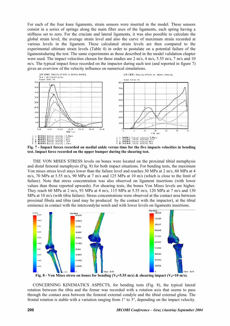
For each of the four knee ligaments, strain sensors were inserted in the model. These sensors consist in a series of springs along the main fiber axes of the ligaments, each spring having a stiffness set to zero. For the cruciate and lateral ligaments, it was also possible to calculate the global strain level, the average strain level and also the curve of maximum strain recorded at various levels in the ligament. These calculated strain levels are then compared to the experimental ultimate strain levels (Table 4) in order to postulate on a potential failure of the ligamentsduring the test. The same experiments as those described in the model validation chapter were used. The impact velocities chosen for these studies are 2 m/s, 4 m/s, 5.55 m/s, 7 m/s and 10 m/s. The typical impact force recorded on the impactor during each test (and reported in figure 7) gives an overview of the velocity influence on numerical simulations.
Fig. 7 - Impact forces recorded on medial ankle versus time for the five impacts velocities in bending
test. Impact force recorded on the upper bumper during the shearing test.
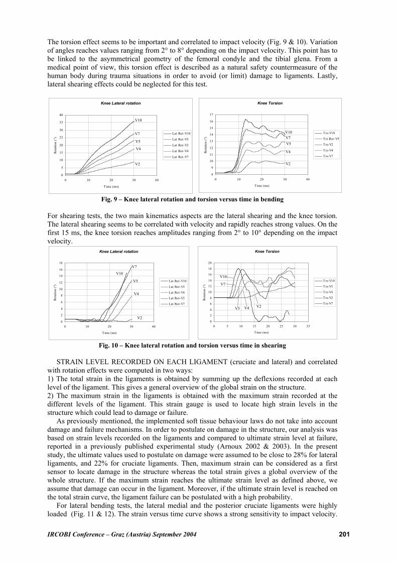
THE VON MISES STRESS levels on bones were located on the proximal tibial metaphysis and distal femoral metaphysis (Fig. 8) for both impact situations. For bending tests, the maximum Von mises stress level stays lower than the failure level and reaches 30 MPa at 2 m/s, 60 MPa at 4 m/s, 70 MPa at 5.55 m/s, 90 MPa at 7 m/s and 125 MPa at 10 m/s (which is close to the limit of failure). Note that stress concentration was also observed on ligament insertions (with lower values than those reported upwards). For shearing tests, the bones Von Mises levels are higher. They reach 60 MPa at 2 m/s, 93 MPa at 4 m/s, 115 MPa at 5.55 m/s, 120 MPa at 7 m/s and 130 MPa at 10 m/s (with tibia failure). Stress concentrations were observed at the contact area between proximal fibula and tibia (and may be produced by the contact with the impactor), at the tibial eminence in contact with the intercondylar notch and with lower levels on ligaments insertions.
Fig. 8 - Von Mises stress on bones for bending (V0=5.55 m/s) & shearing impact (V0=10 m/s).
CONCERNING KINEMATICS ASPECTS, for bending tests (Fig. 8), the typical lateral rotation between the tibia and the femur was recorded with a rotation axis that seems to pass through the contact area between the femoral external condyle and the tibial external glena. The frontal rotation is stable with a variation ranging from 1° to 3°, depending on the impact velocity.
1
2
3
4
5
1
2
3
4
IRCOBI Conference – Graz (Austria) September 2004 201
The torsion effect seems to be important and correlated to impact velocity (Fig. 9 & 10). Variation of angles reaches values ranging from 2° to 8° depending on the impact velocity. This point has to be linked to the asymmetrical geometry of the femoral condyle and the tibial glena. From a medical point of view, this torsion effect is described as a natural safety countermeasure of the human body during trauma situations in order to avoid (or limit) damage to ligaments. Lastly, lateral shearing effects could be neglected for this test.
Knee Lateral rotation
0
5
10
15
20
25
30
35
40
0 10 20 30 40
Time (ms)
Rot
atio
n (
°)
Lat Rot-V10
Lat Rot-V5
Lat Rot-V2
Lat Rot-V4
Lat Rot-V7
Knee Torsion
8
9
10
11
12
13
14
15
16
17
0 10 20 30 40
Time (ms)
Ro
tati
on
(°)
T rs-V10
Trs Rot-V5
Trs-V2
Trs-V4
Trs-V7
Fig. 9 – Knee lateral rotation and torsion versus time in bending
For shearing tests, the two main kinematics aspects are the lateral shearing and the knee torsion. The lateral shearing seems to be correlated with velocity and rapidly reaches strong values. On the first 15 ms, the knee torsion reaches amplitudes ranging from 2° to 10° depending on the impact velocity.
Knee Lateral rotation
0
2
4
6
8
10
12
14
16
18
0 10 20 30 40
Time (ms)
Rot
atio
n (°
)
Lat Rot-V10
Lat Rot-V5
Lat Rot-V4
Lat Rot-V2
Lat Rot-V7
Knee Torsion
0
2
4
6
8
10
12
14
16
18
20
0 5 10 15 20 25 30 35
Time (ms)
Rot
atio
n (°
)
T rs-V10
Trs-V5
Trs-V4
Trs-V2
Trs-V7
Fig. 10 – Knee lateral rotation and torsion versus time in shearing
STRAIN LEVEL RECORDED ON EACH LIGAMENT (cruciate and lateral) and correlated with rotation effects were computed in two ways: 1) The total strain in the ligaments is obtained by summing up the deflexions recorded at each level of the ligament. This gives a general overview of the global strain on the structure. 2) The maximum strain in the ligaments is obtained with the maximum strain recorded at the different levels of the ligament. This strain gauge is used to locate high strain levels in the structure which could lead to damage or failure. As previously mentioned, the implemented soft tissue behaviour laws do not take into account damage and failure mechanisms. In order to postulate on damage in the structure, our analysis was based on strain levels recorded on the ligaments and compared to ultimate strain level at failure, reported in a previously published experimental study (Arnoux 2002 & 2003). In the present study, the ultimate values used to postulate on damage were assumed to be close to 28% for lateral ligaments, and 22% for cruciate ligaments. Then, maximum strain can be considered as a first sensor to locate damage in the structure whereas the total strain gives a global overview of the whole structure. If the maximum strain reaches the ultimate strain level as defined above, we assume that damage can occur in the ligament. Moreover, if the ultimate strain level is reached on the total strain curve, the ligament failure can be postulated with a high probability. For lateral bending tests, the lateral medial and the posterior cruciate ligaments were highly loaded (Fig. 11 & 12). The strain versus time curve shows a strong sensitivity to impact velocity.
V2
V4
V5
V7
V10
V2
V4
V5
V7
V10
V2
V4
V5
V7
V10
V2 V4 V5
V7
V10

IRCOBI Conference – Graz (Austria) September 2004 202
On the opposite, strain versus lateral bending seems to be independent of impact velocity. A small difference between maximum strain level and total strain level seems to show that the medial collateral ligament in the model has homogeneous strain distribution. The maximum strain or total strain level used to postulate on damage in the ligaments is obtained with a lateral rotation ranging from 20 ° to 24 °. Concerning the posterior cruciate ligament, there is a strong difference between global strain (maximum strain) and local strain (maximum strain) which seems to show that local high strain levels were obtained. Local damage could occur for knee rotation between 12 ° and 15 °, whereas global damage for knee lateral rotations was close to 26 ° (which seems to be very high).
Colateral medial ligament: Strain/Time
0
0,1
0,2
0,3
0,4
0,5
0,6
0 10 20 30 40
Time (ms)
Str
ain
Total strain-V10
Maximum strain-V10
Total strain-V5
Maximum strain-V5
Total strain-V2
Maximum strain-V2
Total strain-V4
Maximum strain-V4
Total strain-V7
Maximum strain-V7
Colateral medial ligament: Strain/lateral rotation
0
0,1
0,2
0,3
0,4
0,5
0,6
0 10 20 30 40
Lateral rotation (°)S
train
Total strain-V10
Maximum strain-V10
Total strain-V5
Maximum strain-V5
Total strain-V2
Maximum strain-V2
Total strain-V4
Maximum strain-V4
Total strain-V7
Maximum strain-V7
Fig. 11 – Collateral medial ligament total and maximum strain versus time, lateral rotation
Posterior cruciate ligament: Strain/Time
0
0,1
0,2
0,3
0,4
0,5
0,6
0,7
0 10 20 30 40
Time (ms)
Str
ain
Total strain-V10
Maximum strain-V10
Total strain-V5
Maximum strain-V5
Total strain-V2
Maximum strain-V2
Total strain-V4
Maximum strain-V4
Total strain-V7
Maximum strain-V7
Posterior cruciate ligament: Strain/lateral rotation
0
0,1
0,2
0,3
0,4
0,5
0,6
0,7
0 10 20 30 40
Lateral rotation (°)
Str
ain
Total strain-V10
Maximum strain-V10
Total strain-V5
Maximum strain-V5
Total strain-V2
Maximum strain-V2
Total strain-V4
Maximum strain-V4
Total strain-V7
Maximum strain-V7
Fig. 12 – Posterior cruciate ligament total and maximum strain versus time, lateral rotation
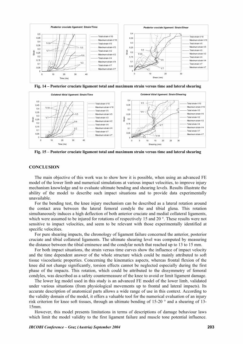
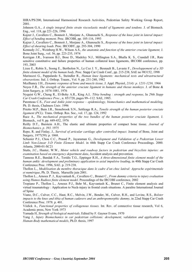
For the shearing tests, the two cruciate and the tibial collateral ligaments were highly loaded (Fig. 13, 14 & 15). As it was observed in bending tests, the effects of impact velocity were significant on strain versus time curves and had no effects on strain versus knee shearing curves. The small dispersion observed between total strain and maximum strain seems to indicate that strain is homogeneous in the anterior cruciate ligaments. The failure or damage could start at a 13 to 15 mm knee shearing. For the posterior cruciate ligament, the strain being not homogeneous on the structure, only maximum strain levels were computed, and they show that damage could occur for shear values ranging from 12 to 14 mm. Finally, for the collateral tibial ligament, the maximum strain reaches up to 14-17mm according to the impact velocity.
Anterior cruciate ligament: Strain/Time
0
0,05
0,1
0,15
0,2
0,25
0,3
0,35
0,4
0,45
0,5
0 10 20 30 40
Time (ms)
Str
ain
Total strain-V10
Maximum strain-V10
Total strain-V5
Maximum strain-V5
Total strain-V4
Maximum strain-V4
Total strain-V2
Maximum strain-V2
Total strain-V7
Maximum strain-V7
Anterior cruciate ligament: Strain/Shearing
0
0,05
0,1
0,15
0,2
0,25
0,3
0,35
0,4
0 5 10 15 20
Shearing (mm)
Str
ain
Total strain-V10
Maximum strain-V10
Total strain-V5
Maximum strain-V5
Total strain-V4
Maximum strain-V4
Total strain-V2
Maximum strain-V2
Total strain-V7
Maximum strain-V7
Fig. 13 – Anterior cruciate ligament total and maximum strain versus time and lateral shearing
V2
V4
V5
V7
V10
V2
V4
V5
V7
V10
V2 V4
V5
V7
V10
V2
V4
V5
V7
V10
V2
V4
V5
V7
V10
V2
V4
V5
V7
V10
V2
V4
V5 V7
V10
IRCOBI Conference – Graz (Austria) September 2004 203
Posterior cruciate ligament: Strain/Time
0
0,05
0,1
0,15
0,2
0,25
0,3
0,35
0,4
0,45
0,5
0 10 20 30 40
Time (ms)
Str
ain
Total strain-V10
Maximum strain-V10
Total strain-V5
Maximum strain-V5
Total strain-V2
Maximum strain-V2
Total strain-V4
Maximum strain-V4
Total strain-V7
Maximum strain-V7
Posterior cruciate ligament: Strain/Shear
0
0,05
0,1
0,15
0,2
0,25
0,3
0,35
0,4
0 10 20 30
Shear (mm)
Str
ain
Total strain-V10
Maximum strain-V10
Total strain-V5
Maximum strain-V5
Total strain-V2
Maximum strain-V2
Total strain-V4
Maximum strain-V4
Total strain-V7
Maximum strain-V7
Fig. 14 – Posterior cruciate ligament total and maximum strain versus time and lateral shearing
Colateral tibial ligament: Strain/Time
0
0,05
0,1
0,15
0,2
0,25
0,3
0,35
0,4
0,45
0,5
0 10 20 30 40
Time (ms)
Str
ain
Total strain-V10
Maximum strain-V10
Total strain-V5
Maximum strain-V5
Total strain-V2
Maximum strain-V2
Total strain-V4
Maximum strain-V4
Total strain-V7
Maximum strain-V7
Colateral tibial ligament: Strain/Shearing
0
0,05
0,1
0,15
0,2
0,25
0,3
0,35
0,4
0 5 10 15 20 25 30
Shearing (mm)
Str
ain
Total strain-V10
Maximum strain-V10
Total strain-V5
Maximum strain-V5
Total strain-V2
Maximum strain-V2
Total strain-V4
Maximum strain-V4
Total strain-V7
Maximum strain-V7
Fig. 15 – Posterior cruciate ligament total and maximum strain versus time and lateral shearing
CONCLUSION
The main objective of this work was to show how it is possible, when using an advanced FE model of the lower limb and numerical simulations at various impact velocities, to improve injury mechanism knowledge and to evaluate ultimate bending and shearing levels. Results illustrate the ability of the model to describe such impact situations and to provide data experimentally unavailable. For the bending test, the knee injury mechanism can be described as a lateral rotation around the contact area between the lateral femoral condyle the and tibial glena. This rotation simultaneously induces a high deflection of both anterior cruciate and medial collateral ligaments, which were assumed to be injured for rotations of respectively 15 and 20 °. These results were not sensitive to impact velocities, and seem to be relevant with those experimentally identified at specific velocities. For pure shearing impacts, the chronology of ligament failure concerned the anterior, posterior cruciate and tibial collateral ligaments. The ultimate shearing level was computed by measuring the distance between the tibial eminence and the condylar notch that reached up to 13 to 15 mm. For both impact situations, the strain versus time curves show the influence of impact velocity and the time dependent answer of the whole structure which could be mainly attributed to soft tissue viscoelastic properties. Concerning the kinematics aspects, whereas frontal flexion of the knee did not change significantly, torsion effects cannot be neglected especially during the first phase of the impacts. This rotation, which could be attributed to the dissymmetry of femoral condyles, was described as a safety countermeasure of the knee to avoid or limit ligament damage. The lower leg model used in this study is an advanced FE model of the lower limb, validated under various situations (from physiological movements up to frontal and lateral impacts). Its accurate description of anatomical parts allows a wide range of use in this context. According to the validity domain of the model, it offers a valuable tool for the numerical evaluation of an injury risk criterion for knee soft tissues, through an ultimate bending of 15-20 ° and a shearing of 13-15mm. However, this model presents limitations in terms of descriptions of damage behaviour laws which limit the model validity to the first ligament failure and muscle tone potential influence.
V2
V4
V5 V7
V10
V2
V4
V5
V7
V10
V2
V4
V5
V7
V10
V2
V4
V5
V7
V10

IRCOBI Conference – Graz (Austria) September 2004 204
These first results have to be improved with further developments, including damage and failure properties of biological tissues and a large sensitivity study of the model in order to define a risk corridor for these ultimate levels. REFERENCES
Arnoux P.J., Modélisation des ligaments des membres porteurs, Ph D. Thesis, 2000. Arnoux P.J., Kang H. S., Kayvantash K., The Radioss Human model for Safety, Archives of Physiology and Biochemistry, vol. 109, 2001, pp. 109. Arnoux P.J., Cavallero C., Chabrand P., Brunet C., Knee ligaments failure under dynamic loadings. International Journal of Crashworthiness, Vol 7 (3), 2002, pp. 255 – 268. Arnoux P. J., Thollon L., Kayvantash K., Behr M., Cavallero C., Brunet C., Advanced lower limb model
with Radioss, application to frontal and lateral impact Radios lower limb model for safety, Proceedings of the IRCOBI Conference, 2002. Atkinson P., A stress based damage criterion to predict articular joint injury from subfracture insult, Ph.D. thesis, 1998. Atkinson P.J., Haut R., Eusebi C., Maripudi V., Hill T., Sambatur K., Development of injury criteria for
human surrogates to address current trends in knee-to-instrument panel injury, in Stapp Car Crash Conference Proceedings, pp. 13-28, 1998. Attarian D.E., Mc. Crackin H.J., Mc. Elhaney J.H., DeVito D.P., Garrett W.E., Biomechanics
characteristics of the human ankle ligaments, Foot and Ankle, vol. 6., N°. 2, pp. 54-58, 1985. Banglmaier, R.F., Dvoracek-Driskna, D., Oniang'o, T.E., and Haut, R.C. Axial compressive load response
of the 90 degrees flexed human tibiofemoral joint,. in 43rd Stapp Car Crash Conf. Proceedings. 1999, p. pp 127-138. Beaugonin M., Haug E., Cesari D., A numerical model of the human ankle/foot under impact loading in
inversion and eversion, in 40th Stapp Car Crash Conference Proceedings, 1996. Beaugonin M., Haug E., Cesari D., Improvement of numerical ankle/foot model: modeling of deformable
bone, in 41th Stapp Car Crash Conference Proc., 1997. Bedewi P.G., Bedewi N.E., Modelling of occupant biomechanics with emphasis on the analysis of lower
extremitiey injuries. International Journal of Crash, Vol. (1): p. 50-72, 1996.
Behr M., Arnoux P. J., Serre T., Bidal S., Kang H.S., Thollon L., Cavallero C., Kayvantash K., Brunet C., A
Human model for Road Safety : From geometrical acquisition to Model Validation with Radioss, International Journal on Computer Methods in Biomechanics and Biomedical Engineering, vol 6 issue 4, 2003. Behr M., Arnoux P.J., Thollon L., Serre T., Cavallero C., Brunet C., Towards integration of muscle tone in
lower limbs subjectes to impacts, IX International Symposium on Computer Simulation in Biomechanics, Juin 2003, Sydney, Australia. Beillas P., Arnoux P. J., Brunet C., Begeman P., Cavallero C., Yang K., King A., Kang H. S., Kayvantash K., Prasad P., Lower Limb: Advanced FE Model and New Experimental Data, International Journal of STAPP - ASME, vol. 45, pp. 469-493 , 2001 Beillas P., Modélisation des membres inférieurs en situation de choc automobile, Ph.D. thesis, École Nationale Supérieure d'Arts et Métiers, Paris, France, 1999 Beillas P., Lavaste F., Nicoloupoulos D., Kayventash K., Yang K. H., Robin S., Foot and ankle finite
element modeling using CT-scan data, in Stapp Car Crash Conference Proc. 1999. Bennett, M.B. and Ker, R.F., The mechanical properties of the human subcalcaneal fat pad in compression.
J. of Anat., 1990(171): p.131-138. Bose D., Bhalla K., Rooij L., Millington S., Studley A., Crandall J., Response of the Knee joint to the
pedestrian impact loading environment, SAE World Congress, paper 2004-01-1608, 2004 Burstein A.H., Currey J.D., Frankel V.H., Reilly D.T., The ultimate properties of bone tissue: the effects of
yielding. J. of Biomech., 1972: p. 35 Crandall J.R., Portier L., Petit P., Hall G.W., Bass C.R., Klopp G.S., Hurwitz S., Pilkey W.D., Trosseille X., Tarriere C., and Lassau J.P., Biomechanical response and physical properties of the leg, foot, and ankle, in 40th Stapp Car Crash Conference Proc. SAE, pp. 173-192, 1996. Goldstein S.A., The mechanical properties of trabecular bone: dependence on anatomic location and
function, Journal of Biomechanics. Vol. 20, (11.12): p. 1055-1061, 1987 Grzegorz Teresinski, Roman Madro, Pelvis and hip injuries as a reconstructive factors in car-to-pedestrian
accidents, Forensic Science International 124, 2001, pp68-73. Haut R. C., Atkinson P. J., Insult to the human cadaver patellofemoral joint : effect of age on fracture
tolerence and occult injury, 39th Stapp Car Crash Conference Proc., no. 952729, SAE, 1995. Hayashi S., Choi H.Y., Levine R.S., Yang K.H., King A.I., Experimental and analytical study of knee
fracture mechanisms in a frontal knee impact, in 40th Stapp Car Crash Conf. Proc. 1996. p. 161.
IRCOBI Conference – Graz (Austria) September 2004 205
IHRA/PS/200, International Harmonized Research Activities, Pedestrian Safety Working Group Report, 2001. Johnson G.A., A single integral finite strain viscoelastic model of ligaments and tendons. J. of Biomech. Eng., vol. 118, pp 221-226, 1996 Kajzer J., Cavallero C., Bonnoit J., Morjane A., Ghanouchi S., Response of the knee joint in lateral impact:
Effect of bending moment. Proc. IRCOBI, pp. 105-116, 1993 Kajzer J., Cavallero C., Bonnoit J., Morjane A., Ghanouchi S., Response of the knee joint in lateral impact:
Effect of shearing loads. Proc. IRCOBY, pp. 293-304, 1990 Kennedy J.C., Weinberg H.W., Wilson A.S., the anatomie and function of the anterior cruciate ligament, J. Bone Joint Surg., vol. 56, pp. 223-235, 1974 Kerrigan J.R., Ivarsson B.J., Bose D., Madeley N.J., Millington S.A., Bhalla K. S., Crandall J.R., Rate sensitive constitutive and failure properties of human collateral knee ligaments, IRCOBI conference, pp. 193, 2003 Lizee E., Robin S., Soong E., Bertholon N., Le Coz J. Y., Besnault B., Lavaste F., Developpement of a 3D
finite element model of the human body, Proc. Stapp Car Crash Conf., pp. 215-238, SAE no 983152, 1998 Marinozzi G., Pappalardo S., Steindler R., Human knee ligaments: mechanical tests and ultrastructural
obseravtions. Ital. J. Orthop. Traum., Vol. 9, pp. 231-240, 1982 Mcelhaney J.H., Dynamic response of bone and muscle tissue, J. Appl. Physiol, 21(4): p. 1231-1236, 1966 Noyes F.R., The strength of the anterior cruciate ligament in humans and rhesus monkeys. J. of Bone & Joint Surgery, p. 1074-1081, 1976 Nyquist G.W., Cheng R., El-Bohy A.R., King A.I.. Tibia bending : strength and response, In 29th Stapp
Car Crash Conference Proc., n. 851728, pages 99--112. SAE, 1985. Parenteau C.S., Foot and Ankle joint response – epidemiology, biomechanics and mathematical modeling, Ph. D. thesis, Chalmers Univ. 1996 Prietto M.P., Bain J.R., Stonebrook S.N., Settleage R.A., Tensile strength of the human posterior cruciate
ligament (PCL). Trans. Orthop. Res. Soc., vol. 17, pp. 124, 1992 Race A., The mechanical properties of the two bundles of the human posterior cruciate ligament, J. Biomech., vol 9, pp. 449-452, 1976 Reilly D.T., Burstein A.H., The elastic and ultimate properties of compact bone tissue. Journal of
Biomechanics, p. 393. 1975 Repo, R. and Finlay, J., Survival of articular cartilage after controlled impact. Journal of Bone, Joint and Surgery, 1977(59): p. 1068. Schuster P.J., Chou C.C., Prasad P., Jayaraman G., Development and Validation of a Pedestrian Lower
Limb Non-Linear 3-D Finite Element Model. in 44th Stapp Car Crash Conference Proceedings. 2000. Atlanta, 2000-01-SC21 Stutts, J.C., Hunter, W.W., Motor vehicle and roadway factors in pedestrian and bicyclists injuries: an
examination based on emergency department data, Accident analysis and prevention. Tannous R.E., Bandak F.A., Toridis T.G., Eppinger R.H., A three-dimensional finite element model of the
human ankle: development and preliminary application to axial impulsive loading, in 40th Stapp Car Crash Conference Proc. 1996, SAE. p. 219-238. Thollon L., Modélisation du membre thoracique dans le cadre d’un choc latéral: Approche expérimentale
et numérique, Ph. D. Thesis, Marseille juin 2001. Thollon L., Arnoux P. J., Kayvantash K., Cavallero C., Brunet C., From dummy criteria to injury evaluation
using Humos Radioss finite element model. Proceedings of the IRCOBI conference, 2002
Tropiano P., Thollon L., Arnoux P.J., Behr M., Kayvantash K., Brunet C., Finite element analysis and virtual traumatology : Application to Neck-injury in frontal crash situations. A paraître International Journal of Spine Viano, D.C., Culver, C.C., Haut, R.C., Melvin, J.W., Bender, M., Culver, R.H., and Levine, R.S., Bolster
impacts to the knee and tibia of human cadavers and an anthropomorphic dummy, in 22nd Stapp Car Crash Conference Proc. 1978. p. 401. Viidick A., Functional properties of collagenous tissues. Int. Rev. of connective tissue research, Vol 6, Academic press, New York 1973 Yamada H, Strength of biological matérials. Edited by F. Gaynor Evans, 1970 Yang J., Injury Biomechanics in car pedestrian collisions: development, validation and application of
Human-Body mathematical models, Ph.D. thesis, 1997


