PE1 Pellet - Touch...The Froling PE1 Pellet 7, PE1 Pellet 10, PE1 Pellet 15, PE1 Pellet 20, PE1...
32
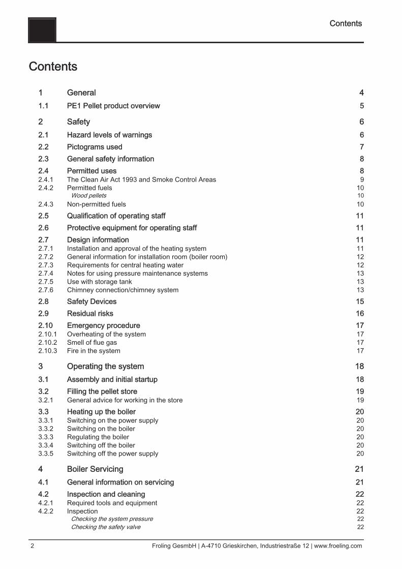
Operating Instructions Pellet boiler PE1 Pellet (Touch) Translation of the original German operating instructions for the operator Read and follow the instructions and safety information! Technical changes, typographical errors and omissions reserved! B1000315_en | Edition 30/06/2015 Froling GesmbH | A-4710 Grieskirchen, Industriestraße 12 | www.froeling.com
Transcript of PE1 Pellet - Touch...The Froling PE1 Pellet 7, PE1 Pellet 10, PE1 Pellet 15, PE1 Pellet 20, PE1...
Operating Instructions
Pellet boiler PE1 Pellet (Touch)
Translation of the original German operating instructions for the operatorRead and follow the instructions and safety information!
Technical changes, typographical errors and omissions reserved!B1000315_en | Edition 30/06/2015
Froling GesmbH | A-4710 Grieskirchen, Industriestraße 12 | www.froeling.com
Contents
1 General 41.1 PE1 Pellet product overview 5
2 Safety 62.1 Hazard levels of warnings 62.2 Pictograms used 72.3 General safety information 82.4 Permitted uses 82.4.1 The Clean Air Act 1993 and Smoke Control Areas 92.4.2 Permitted fuels 10 Wood pellets 102.4.3 Non-permitted fuels 102.5 Qualification of operating staff 112.6 Protective equipment for operating staff 112.7 Design information 112.7.1 Installation and approval of the heating system 112.7.2 General information for installation room (boiler room) 122.7.3 Requirements for central heating water 122.7.4 Notes for using pressure maintenance systems 132.7.5 Use with storage tank 132.7.6 Chimney connection/chimney system 132.8 Safety Devices 152.9 Residual risks 162.10 Emergency procedure 172.10.1 Overheating of the system 172.10.2 Smell of flue gas 172.10.3 Fire in the system 17
3 Operating the system 183.1 Assembly and initial startup 183.2 Filling the pellet store 193.2.1 General advice for working in the store 193.3 Heating up the boiler 203.3.1 Switching on the power supply 203.3.2 Switching on the boiler 203.3.3 Regulating the boiler 203.3.4 Switching off the boiler 203.3.5 Switching off the power supply 20
4 Boiler Servicing 214.1 General information on servicing 214.2 Inspection and cleaning 224.2.1 Required tools and equipment 224.2.2 Inspection 22 Checking the system pressure 22 Checking the safety valve 22
Contents
2 Froling GesmbH | A-4710 Grieskirchen, Industriestraße 12 | www.froeling.com
4.2.3 Cleaning 23 Emptying the ashcan (PE1 Pellet 7-10) 23 Emptying the ash container (PE1 Pellet 15-35) 23 Cleaning the grate and combustion chamber 244.2.4 Periodic inspection and cleaning 25 Cleaning the heat exchanger 25 Cleaning the flue gas pipe 26 Checking the draught controller flap 264.2.5 Inspection and cleaning the DHW tank unit (optional) 26 Safety devices 26 Pressure reducing valve 26 Magnesium corrosion protection anode 27 Interior cleaning / removing limescale deposits 27
4.3 Emissions measurement by chimney sweep or regulatory body 284.4 Maintenance agreement / Customer service 284.5 Replacement parts 284.6 Disposal information 294.6.1 Disposal of the ash 294.6.2 Disposal of system components 29
5 Troubleshooting 305.1 General fault with power supply 305.1.1 Behaviour of system after a power failure 305.2 Excessive temperature 305.3 Faults with fault message 315.3.1 Procedure for fault messages 315.3.2 Acknowledging a fault message 31
6 Appendix 326.1 Addresses 326.1.1 Address of manufacturer 326.1.2 Address of the installer 32
Contents
Operating Instructions PE1 Pellet (Touch) | B1000315_en 3
1 GeneralThank you for choosing a quality product from Froling. The product features a state-of-the-art design and conforms to all currently applicable standards and testingguidelines.Please read and observe the documentation provided and always keep it close to thesystem for reference. Observing the requirements and safety information in thedocumentation makes a significant contribution to safe, appropriate, environmentallyfriendly and economical operation of the system.The constant further development of our products means that there may be minordifferences from the pictures and content. If you discover any errors, please let usknow: [email protected] to technical change.
Warranty and Guarantee Conditions
Our sale and delivery conditions will be applicable. These conditions have been madeavailable to customers, and customers have been made aware of them at the time oforder completion.You can also find the guarantee conditions on the enclosed guarantee certificate.
1 General
4 Froling GesmbH | A-4710 Grieskirchen, Industriestraße 12 | www.froeling.com
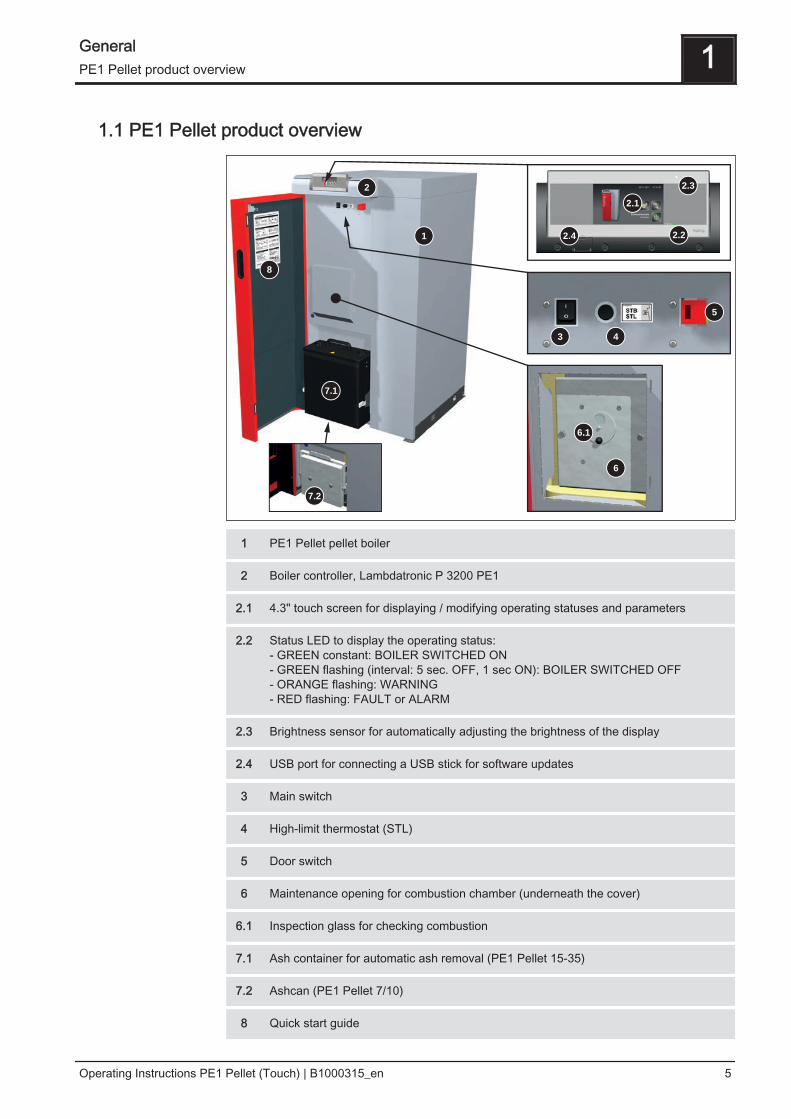
1.1 PE1 Pellet product overview
4
7.1
7.2
8
6
5
1
2
3
2.2
6.1
2.4
2.3
2.1
1 PE1 Pellet pellet boiler
2 Boiler controller, Lambdatronic P 3200 PE1
2.1 4.3" touch screen for displaying / modifying operating statuses and parameters
2.2 Status LED to display the operating status:- GREEN constant: BOILER SWITCHED ON- GREEN flashing (interval: 5 sec. OFF, 1 sec ON): BOILER SWITCHED OFF- ORANGE flashing: WARNING- RED flashing: FAULT or ALARM
2.3 Brightness sensor for automatically adjusting the brightness of the display
2.4 USB port for connecting a USB stick for software updates
3 Main switch
4 High-limit thermostat (STL)
5 Door switch
6 Maintenance opening for combustion chamber (underneath the cover)
6.1 Inspection glass for checking combustion
7.1 Ash container for automatic ash removal (PE1 Pellet 15-35)
7.2 Ashcan (PE1 Pellet 7/10)
8 Quick start guide
General 1PE1 Pellet product overview
Operating Instructions PE1 Pellet (Touch) | B1000315_en 5
2 Safety
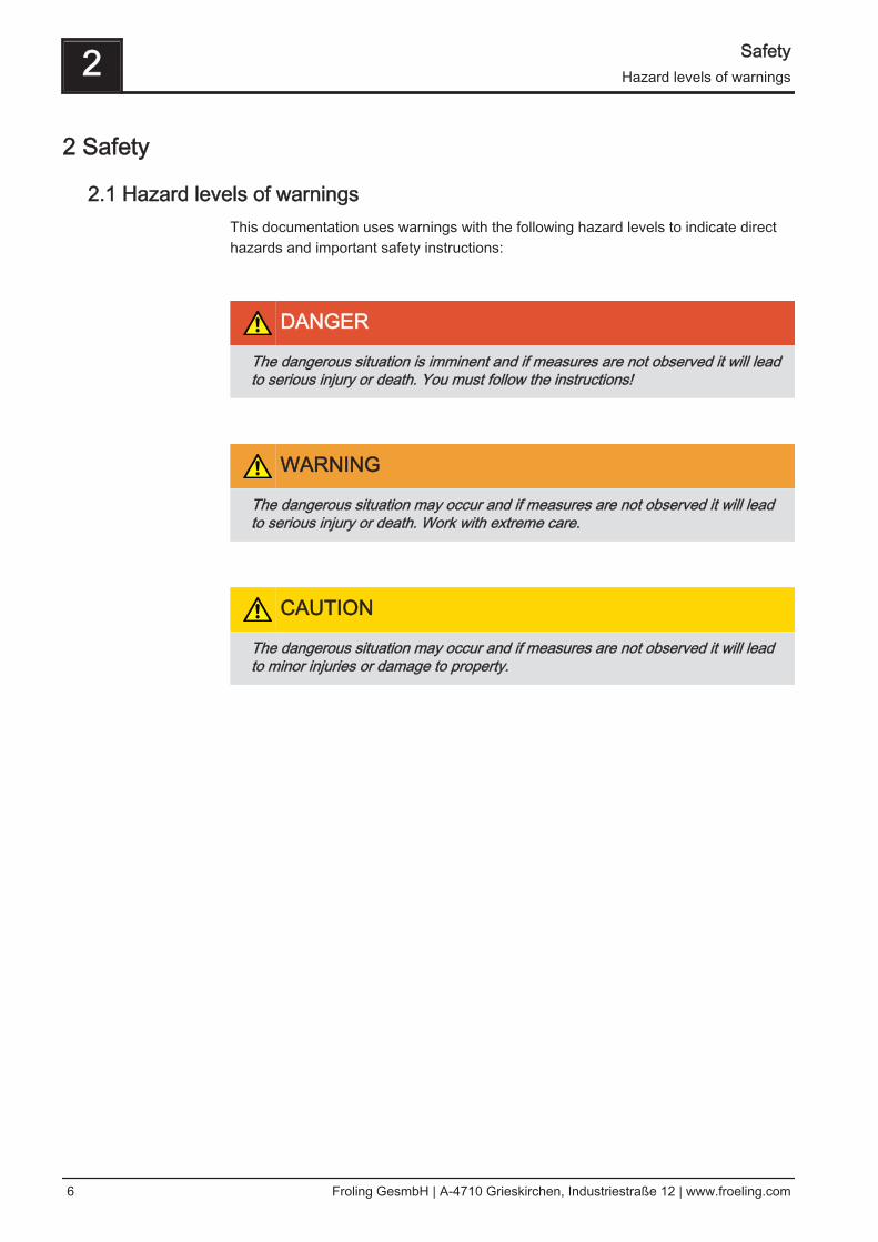
2.1 Hazard levels of warningsThis documentation uses warnings with the following hazard levels to indicate directhazards and important safety instructions:
DANGER
The dangerous situation is imminent and if measures are not observed it will leadto serious injury or death. You must follow the instructions!
WARNING
The dangerous situation may occur and if measures are not observed it will leadto serious injury or death. Work with extreme care.
CAUTION
The dangerous situation may occur and if measures are not observed it will leadto minor injuries or damage to property.
2 SafetyHazard levels of warnings
6 Froling GesmbH | A-4710 Grieskirchen, Industriestraße 12 | www.froeling.com
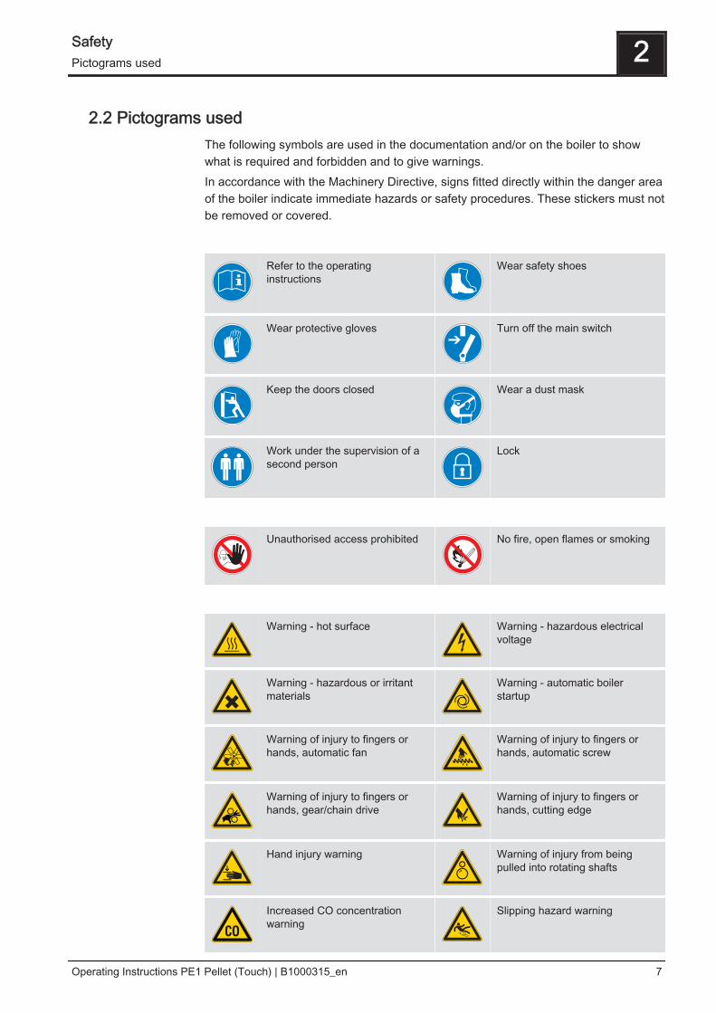
2.2 Pictograms usedThe following symbols are used in the documentation and/or on the boiler to showwhat is required and forbidden and to give warnings.In accordance with the Machinery Directive, signs fitted directly within the danger areaof the boiler indicate immediate hazards or safety procedures. These stickers must notbe removed or covered.
Refer to the operatinginstructions
Wear safety shoes
Wear protective gloves Turn off the main switch
Keep the doors closed Wear a dust mask
Work under the supervision of asecond person
Lock
Unauthorised access prohibited No fire, open flames or smoking
Warning - hot surface Warning - hazardous electricalvoltage
Warning - hazardous or irritantmaterials
Warning - automatic boilerstartup
Warning of injury to fingers orhands, automatic fan
Warning of injury to fingers orhands, automatic screw
Warning of injury to fingers orhands, gear/chain drive
Warning of injury to fingers orhands, cutting edge
Hand injury warning Warning of injury from beingpulled into rotating shafts
Increased CO concentrationwarning
Slipping hazard warning
Safety 2Pictograms used
Operating Instructions PE1 Pellet (Touch) | B1000315_en 7
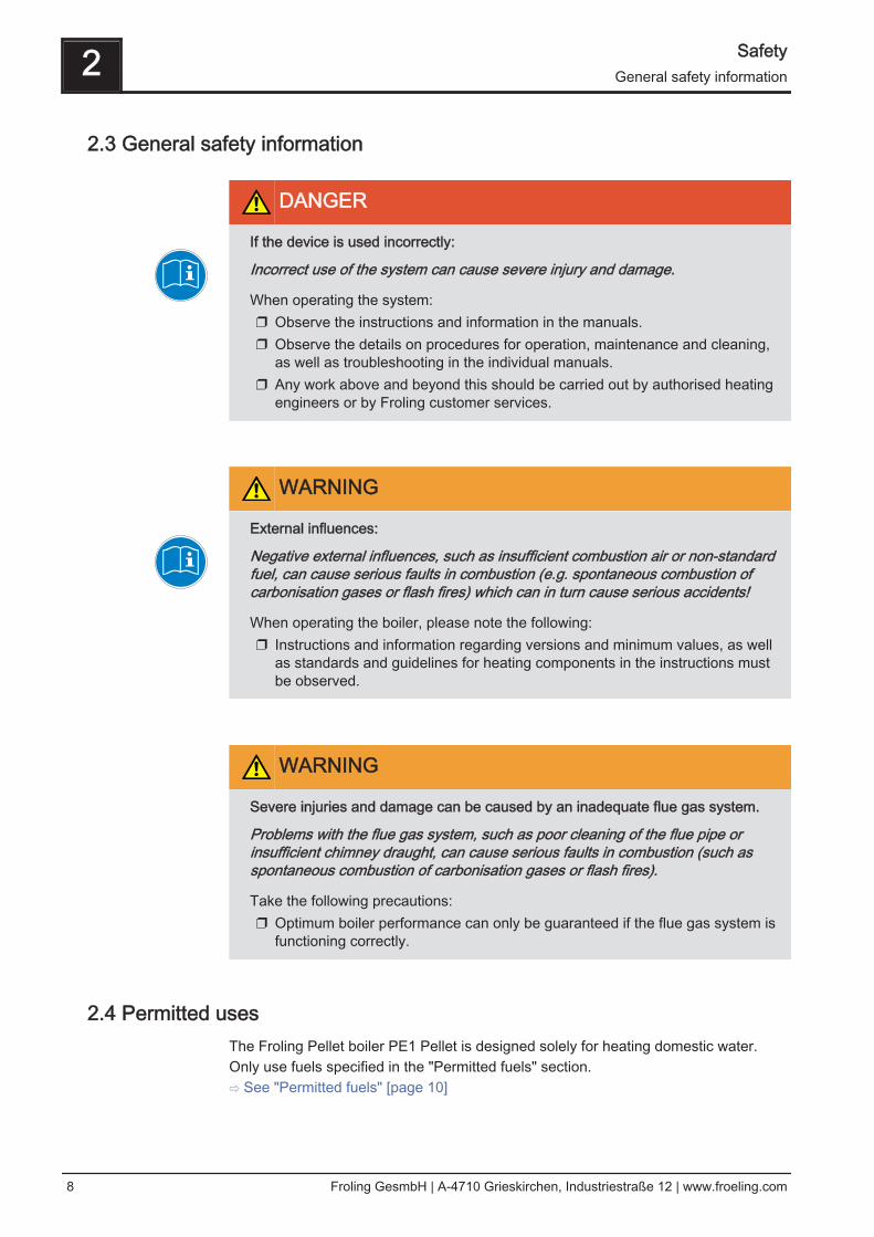
2.3 General safety information
DANGER
If the device is used incorrectly:
Incorrect use of the system can cause severe injury and damage.
When operating the system:❒ Observe the instructions and information in the manuals.❒ Observe the details on procedures for operation, maintenance and cleaning,
as well as troubleshooting in the individual manuals.❒ Any work above and beyond this should be carried out by authorised heating
engineers or by Froling customer services.
WARNING
External influences:
Negative external influences, such as insufficient combustion air or non-standardfuel, can cause serious faults in combustion (e.g. spontaneous combustion ofcarbonisation gases or flash fires) which can in turn cause serious accidents!
When operating the boiler, please note the following:❒ Instructions and information regarding versions and minimum values, as well
as standards and guidelines for heating components in the instructions mustbe observed.
WARNING
Severe injuries and damage can be caused by an inadequate flue gas system.
Problems with the flue gas system, such as poor cleaning of the flue pipe orinsufficient chimney draught, can cause serious faults in combustion (such asspontaneous combustion of carbonisation gases or flash fires).
Take the following precautions:❒ Optimum boiler performance can only be guaranteed if the flue gas system is
functioning correctly.
2.4 Permitted usesThe Froling Pellet boiler PE1 Pellet is designed solely for heating domestic water.Only use fuels specified in the "Permitted fuels" section.⇨ See "Permitted fuels" [page 10]
2 SafetyGeneral safety information
8 Froling GesmbH | A-4710 Grieskirchen, Industriestraße 12 | www.froeling.com
The unit should only be operated when it is in full working order. It must be operated inaccordance with the instructions, observing safety precautions, and you should ensureyou are aware of the potential hazards. The inspection and cleaning intervals in theoperating instructions must be observed. Ensure that any faults which might impairsafety are rectified immediately.The manufacturer or supplier is not liable for any damage resulting from non-permitteduses.Only original spare parts or specific alternative spare parts authorised by themanufacturer may be used. Any kind of change or modification made to the productwill invalidate its manufacturer’s CE conformity. In such cases, the product will need toundergo new hazard evaluation procedures by the operator. The operator will then befully responsible for the declaration of conformity according to the valid guideline(s) forthe product and will need to attach the new CE label to the device. This person willthen assume all of the rights and responsibilities of a manufacturer.
2.4.1 The Clean Air Act 1993 and Smoke Control AreasUnder the Clean Air Act local authorities may declare the whole or part of the district ofthe authority to be a smoke control area. It is an offence to emit smoke from achimney of a building, from a furnance or from any fixed boiler if located in adesignated smoke control area. It is also an offence to acquire an „unauthorisedfuel“ for use within a smoke control area unless it is used in an „exempt“ appliance(„exempted“ from the controls which generally apply in the smoke control area). TheSecretary of State for Environment, Food and Rural Affairs has powers under the Actto authorise smokeless fuels or exempt appliances for use in smoke control areas inEngland. In Scotland and Wales this power rests with Ministers in the devolvedadministrations for those countries. Separate legislation, the Clean Air (NorthernIreland) Order 1981, applies in Northern Ireland. Therefore it is a requirement thatfuels burnt or obtained for use in smoke control areas have been „authorised“ inRegulations and that appliances used to burn solid fuel in those areas (other than„authorised“ fuels) have been exempted by an Order made and signed by theSecretary of State or Minister in the devolved administrations.Further information on the requirements of the Clean Air Act can be found here: http://smokecontrol.defra.gov.ukYour local authority is responsible for implementing the Clean Air Act 1993 includingdesignation and supervision of smoke control areas and you can contact them fordetails of Clean Air Act requirements.The Froling PE1 Pellet 7, PE1 Pellet 10, PE1 Pellet 15, PE1 Pellet 20, PE1 Pellet 25,PE1 Pellet 30 and PE1 Pellet 35 have been recommended as suitable for use insmoke control areas when burning fuels as listed under "Permitted fuels".
Safety 2Permitted uses
Operating Instructions PE1 Pellet (Touch) | B1000315_en 9
2.4.2 Permitted fuels
Wood pelletsWood pellets made from natural wood with a diameter of 6 mm
EU: Fuel acc. to EN ISO 17225 - Part 2: Wood pellets class A1 / D06
and/or: ENplus / DINplus certification scheme
General note:Before refilling the store, check for pellet dust and clean if necessary.
2.4.3 Non-permitted fuelsThe use of fuels not defined in the "Permitted fuels" section, and particularly theburning of refuse, is not permitted.
CAUTION
In case of use of non-permitted fuels:
Burning non-permitted fuels increases the cleaning requirements and leads to abuild-up of aggressive sedimentation and condensation, which can damage theboiler and also invalidates the guarantee. Using non-standard fuels can also leadto serious problems with combustion.
For this reason, when operating the boiler:❒ Only use permitted fuels
Note on standards
2 SafetyPermitted uses
10 Froling GesmbH | A-4710 Grieskirchen, Industriestraße 12 | www.froeling.com
2.5 Qualification of operating staff
CAUTION
If unauthorised persons enter the installation room / boiler room:
Risk of personal injury and damage to property
❒ The operator is responsible for keeping unauthorised persons, in particularchildren, away from the system.
Only trained operators are permitted to operate the unit. The operator must also haveread and understood the instructions in the documentation.
2.6 Protective equipment for operating staffYou must ensure that staff have the protective equipment specified by accidentprevention regulations.
▪ For operation, inspection and cleaning:- suitable work wear- protective gloves- sturdy shoes
2.7 Design informationIt is forbidden to carry out modifications to the boiler or to change or deactivate safetyequipment.Always comply with all fire, building, and electrical regulations when installing oroperating the boiler system, and follow the operating instructions and mandatoryregulations that apply in the country in which the boiler is operated.
2.7.1 Installation and approval of the heating systemThe boiler should be operated in a closed heating system. The following standardsgovern the installation:
ÖNORM / DIN EN 12828 Heating Systems in Buildings
NOTICE! Each heating system must be officially approved.The appropriate supervisory authority (inspection agency) must always be informedwhen installing or modifying a heating system, and authorisation must be obtainedfrom the building authorities:Austria: report to the construction authorities of the community or magistrateGermany: report new installations to an approved chimney sweep / the buildingauthorities.
Note on standards
Safety 2Qualification of operating staff
Operating Instructions PE1 Pellet (Touch) | B1000315_en 11
2.7.2 General information for installation room (boiler room)
Boiler room characteristics▪ There must not be a potentially explosive atmosphere in the boiler room as the
boiler is not suitable for use in potentially explosive environments.▪ The boiler room must be frost-free.▪ The boiler does not provide any light, so the customer must provide sufficient light‐
ing in the boiler room in accordance with national workplace design regulations.▪ When using the boiler over 2000 metres above sea level you should consult the
manufacturer.▪ Danger of fire due to flammable materials.
No flammable materials should be stored near the boiler. Flammable objects (e.g.clothing) must not be put on the boiler to dry.
▪ Damage due to impurities in combustion air.Do not use any solvents or cleaning agents containing chlorine in the room wherethe boiler is installed.
▪ Keep the air suction opening of the boiler free from dust.
Ventilation of the boiler roomVentilation air for the boiler room should be taken from and expelled directly outside,and the openings and air ducts should be designed to prevent weather conditions(foliage, snowdrifts, etc.) from obstructing the air flow. Unless otherwise specified in the applicable building regulations for the boiler room,the following standards apply to the design and dimensions of the air ducts:
ÖNORM H 5170 - Construction and fire protection requirementsTRVB H118 - Technical directives on fire protection/prevention
2.7.3 Requirements for central heating water
Austria:Germany:Switzerland:Italy:
ÖNORM H 5195VDI 2035SWKI 97-1D.P.R. no. 412
NOTICE! Note on filling with make-up water: Always bleed the filling hose beforeconnecting, in order to prevent air from entering the system. Observe the standards and also follow the recommendations below:❒ Max. cumulative value for alkaline earth: 1.0 mmol/l or 100 mg/l (equivalent to
5.6 dH)❒ Use prepared water which complies with the standards cited above for filling and
makeup water❒ Avoid leaks and use a closed heating system to maintain water quality during
operation
Note on standards
Note on standards
2 SafetyDesign information
12 Froling GesmbH | A-4710 Grieskirchen, Industriestraße 12 | www.froeling.com
2.7.4 Notes for using pressure maintenance systemsPressure maintenance systems in hot-water heating systems keep the requiredpressure within predefined limits and balance out volume variations caused bychanges in the hot-water temperature. Two main systems are used:
Compressor-controlled pressure maintenance
In compressor-controlled pressure maintenance units, a variable air cushion in theexpansion tank is responsible for volume compensation and pressure maintenance. Ifthe pressure is too low, the compressor pumps air into the tank. If the pressure is toohigh, air is released by means of a solenoid valve. The systems are built solely withclosed-diaphragm expansion tanks to prevent the damaging introduction of oxygeninto the heating water.
Pump-controlled pressure maintenance
A pump-controlled pressure maintenance unit essentially consists of a pressure-maintenance pump, relief valve and an unpressurised receiving tank. The valvereleases hot water into the receiving tank if the pressure is too high. If the pressuredrops below a preset value, the pump draws water from the receiving tank and feeds itback into the heating system. Pump-controlled pressure maintenance systems withopen expansion tanks (e.g. without a diaphragm) introduce ambient oxygen via thesurface of the water, exposing the connected system components to the risk ofcorrosion. These systems offer no oxygen removal for the purposes of corrosioncontrol as required by VDI 2035 and in the interests of corrosion protection should notbe used.
2.7.5 Use with storage tank
NOTICE
In principle it is not necessary to use a storage tank for the system to runsmoothly. However, we recommend that you use the system with a storage tank,as this ensures a continuous supply of fuel in the ideal output range of the boiler.
For the correct dimensions of the storage tank and the line insulation (in accordancewith ÖNORM M 7510 or guideline UZ37) please consult your installer or Froling. ⇨ See "Addresses" [page 32]
2.7.6 Chimney connection/chimney systemEN 303-5 specifies that the entire flue gas system must be designed to prevent,wherever possible, damage caused by seepage, insufficient feed pressure andcondensation. Please note in this respect that flue gas temperatures lower than 160Kabove room temperature can occur in the permitted operating range of the boiler.
Safety 2Design information
Operating Instructions PE1 Pellet (Touch) | B1000315_en 13
NOTICE! Please see the technical data contained in the assembly instructions forfurther information about standards and regulations as well as the flue gastemperatures when clean and the other flue gas values!
2 SafetyDesign information
14 Froling GesmbH | A-4710 Grieskirchen, Industriestraße 12 | www.froeling.com
2.8 Safety Devices
SV
4
5
3
2.1
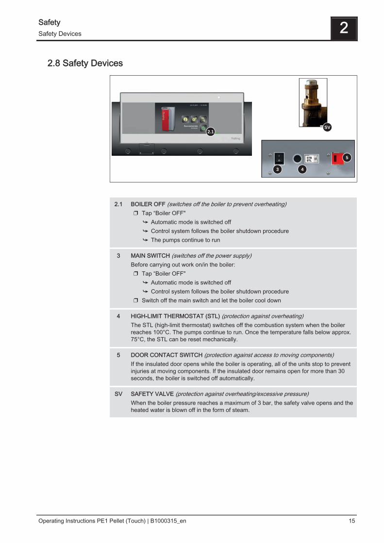
2.1 BOILER OFF (switches off the boiler to prevent overheating)❒ Tap “Boiler OFF"
➥ Automatic mode is switched off➥ Control system follows the boiler shutdown procedure➥ The pumps continue to run
3 MAIN SWITCH (switches off the power supply)Before carrying out work on/in the boiler:❒ Tap “Boiler OFF"
➥ Automatic mode is switched off➥ Control system follows the boiler shutdown procedure
❒ Switch off the main switch and let the boiler cool down
4 HIGH-LIMIT THERMOSTAT (STL) (protection against overheating)The STL (high-limit thermostat) switches off the combustion system when the boilerreaches 100°C. The pumps continue to run. Once the temperature falls below approx.75°C, the STL can be reset mechanically.
5 DOOR CONTACT SWITCH (protection against access to moving components)If the insulated door opens while the boiler is operating, all of the units stop to preventinjuries at moving components. If the insulated door remains open for more than 30seconds, the boiler is switched off automatically.
SV SAFETY VALVE (protection against overheating/excessive pressure)When the boiler pressure reaches a maximum of 3 bar, the safety valve opens and theheated water is blown off in the form of steam.
Safety 2Safety Devices
Operating Instructions PE1 Pellet (Touch) | B1000315_en 15
2.9 Residual risks
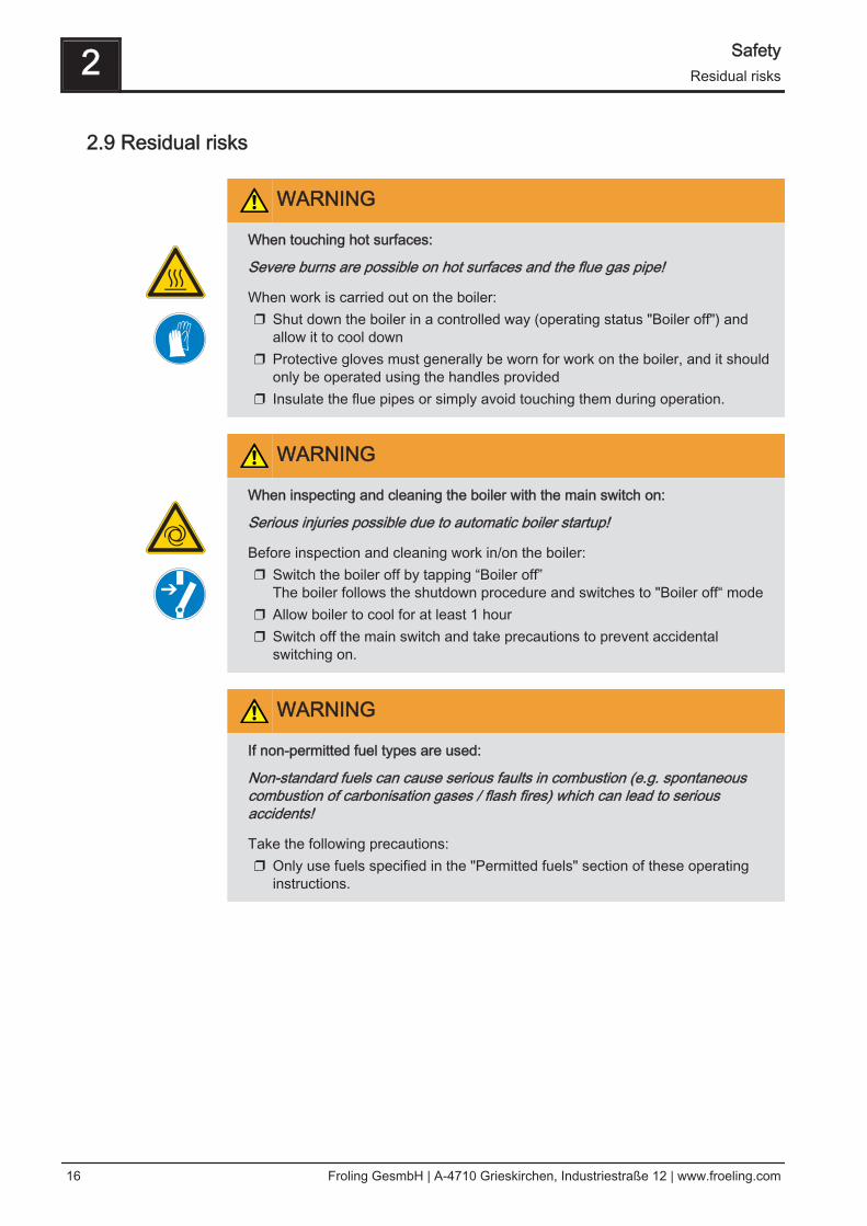
WARNING
When touching hot surfaces:
Severe burns are possible on hot surfaces and the flue gas pipe!
When work is carried out on the boiler:❒ Shut down the boiler in a controlled way (operating status "Boiler off") and
allow it to cool down❒ Protective gloves must generally be worn for work on the boiler, and it should
only be operated using the handles provided❒ Insulate the flue pipes or simply avoid touching them during operation.
WARNING
When inspecting and cleaning the boiler with the main switch on:
Serious injuries possible due to automatic boiler startup!
Before inspection and cleaning work in/on the boiler:❒ Switch the boiler off by tapping “Boiler off”
The boiler follows the shutdown procedure and switches to "Boiler off“ mode❒ Allow boiler to cool for at least 1 hour❒ Switch off the main switch and take precautions to prevent accidental
switching on.
WARNING
If non-permitted fuel types are used:
Non-standard fuels can cause serious faults in combustion (e.g. spontaneouscombustion of carbonisation gases / flash fires) which can lead to seriousaccidents!
Take the following precautions:❒ Only use fuels specified in the "Permitted fuels" section of these operating
instructions.
2 SafetyResidual risks
16 Froling GesmbH | A-4710 Grieskirchen, Industriestraße 12 | www.froeling.com
2.10 Emergency procedure
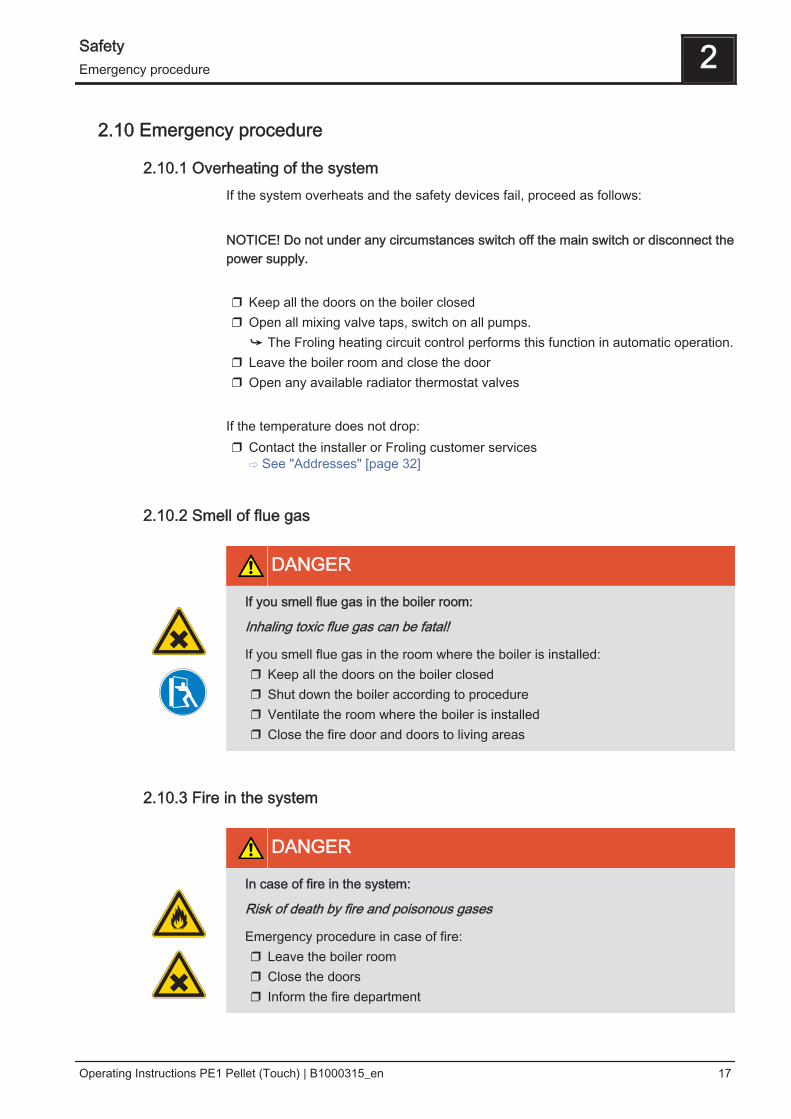
2.10.1 Overheating of the systemIf the system overheats and the safety devices fail, proceed as follows: NOTICE! Do not under any circumstances switch off the main switch or disconnect thepower supply. ❒ Keep all the doors on the boiler closed❒ Open all mixing valve taps, switch on all pumps.
➥ The Froling heating circuit control performs this function in automatic operation.❒ Leave the boiler room and close the door❒ Open any available radiator thermostat valves
If the temperature does not drop:❒ Contact the installer or Froling customer services
⇨ See "Addresses" [page 32]
2.10.2 Smell of flue gas
DANGER
If you smell flue gas in the boiler room:
Inhaling toxic flue gas can be fatal!
If you smell flue gas in the room where the boiler is installed:❒ Keep all the doors on the boiler closed❒ Shut down the boiler according to procedure❒ Ventilate the room where the boiler is installed❒ Close the fire door and doors to living areas
2.10.3 Fire in the system
DANGER
In case of fire in the system:
Risk of death by fire and poisonous gases
Emergency procedure in case of fire:❒ Leave the boiler room❒ Close the doors❒ Inform the fire department
Safety 2Emergency procedure
Operating Instructions PE1 Pellet (Touch) | B1000315_en 17
3 Operating the system
3.1 Assembly and initial startupAssembly, installation and initial startup of the boiler must only be carried out byqualified staff, and these procedures are described in the accompanying assemblyinstructions.NOTICE! See assembly instructions for the PE1 Pellet
NOTICE
Optimum efficiency and efficient, low-emission operation can only be guaranteedif the system is set up by trained professionals and the standard factory settingsare observed.
Take the following precautions:❒ Initial startup should be carried out with an authorised installer or with Froling
customer services
The individual steps for initial start-up are explained in the operating instructions forthe controllerNOTICE! See operating instructions for the Lambdatronic P 3200 PE1 The customer is responsible for ensuring the following prior to initial start-up of thesystem by Froling customer services:▪ Electrical installation▪ Installation of water pipes▪ Flue gas connection including all insulation work▪ Work must comply with local fire protection regulations
▪ It is essential that the electrician who has carried out the installation work is
available when starting up the system for the first time to make any changes to thewiring which may become necessary.
▪ During initial start-up, operating staff are shown how to use the boiler. It isimperative for proper handover of the product that those involved are present asthis is a one-off opportunity.
3 Operating the systemAssembly and initial startup
18 Froling GesmbH | A-4710 Grieskirchen, Industriestraße 12 | www.froeling.com
3.2 Filling the pellet store
CAUTION
Filling the store when the boiler is switched on
could result in damage and consequential injury!
When filling the fuel store:❒ Switch off the boiler by tapping “Boiler OFF”
➥ The boiler follows the shutdown procedure and switches to "Boiler off"status
❒ Allow the boiler to cool for at least half an hour
When the boiler has cooled down:❒ Before filling check the store for fines and clean if necessary
➥ Observe the general advice for working in the store.⇨ See "General advice for working in the store" [page 19]
❒ Close all openings to the store to seal out dust❒ Fill the store with pellets
➥ Only use permitted pellets⇨ See "Permitted fuels" [page 10]
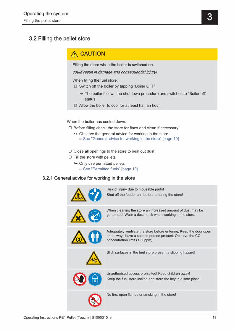
3.2.1 General advice for working in the store
Risk of injury due to moveable parts!Shut off the feeder unit before entering the store!
When cleaning the store an increased amount of dust may begenerated. Wear a dust mask when working in the store.
Adequately ventilate the store before entering. Keep the door openand always have a second person present. Observe the COconcentration limit (< 30ppm).
Slick surfaces in the fuel store present a slipping hazard!
Unauthorised access prohibited! Keep children away!Keep the fuel store locked and store the key in a safe place!
No fire, open flames or smoking in the store!
Operating the system 3Filling the pellet store
Operating Instructions PE1 Pellet (Touch) | B1000315_en 19
3.3 Heating up the boiler
NOTICE
Do not modify the factory settings!
Changing the system's factory settings can be detrimental to efficiency andemissions of the system.
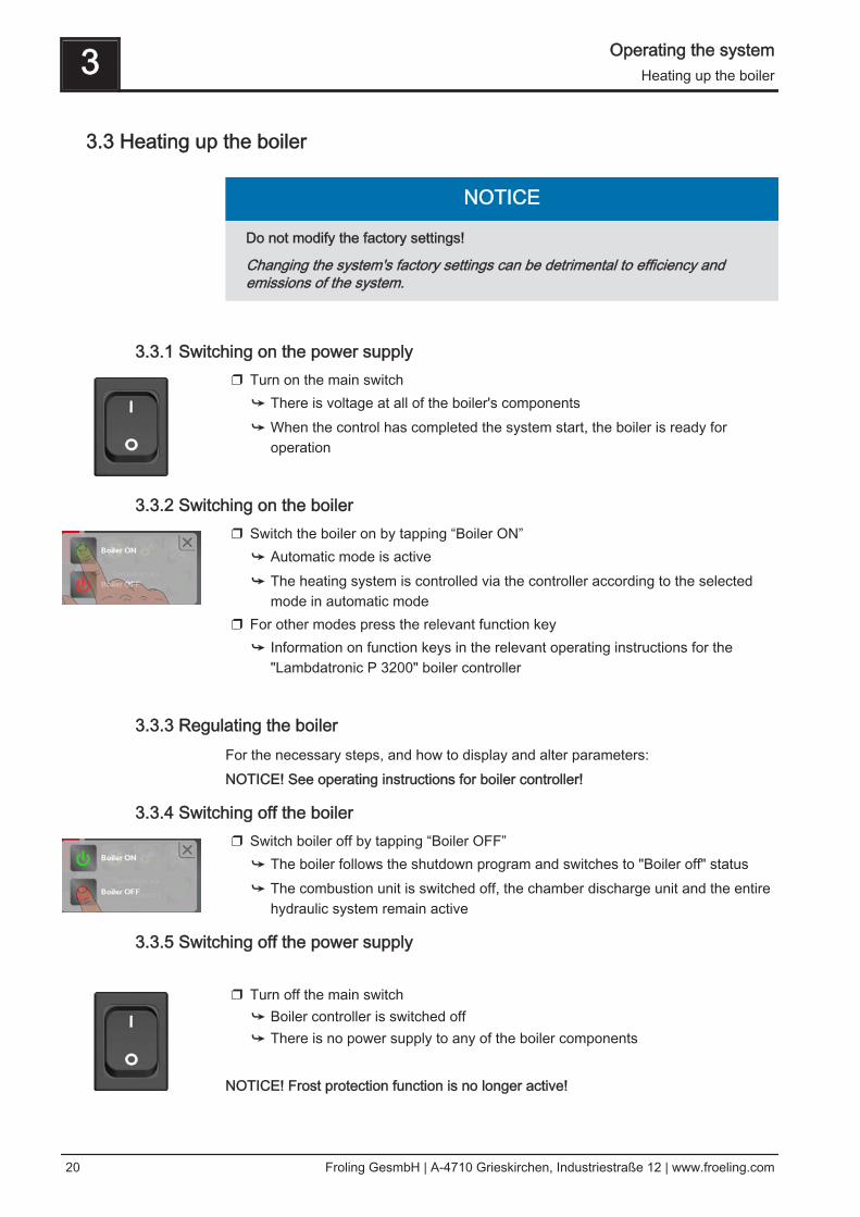
3.3.1 Switching on the power supply❒ Turn on the main switch
➥ There is voltage at all of the boiler's components➥ When the control has completed the system start, the boiler is ready for
operation
3.3.2 Switching on the boiler❒ Switch the boiler on by tapping “Boiler ON”
➥ Automatic mode is active➥ The heating system is controlled via the controller according to the selected
mode in automatic mode❒ For other modes press the relevant function key
➥ Information on function keys in the relevant operating instructions for the"Lambdatronic P 3200" boiler controller
3.3.3 Regulating the boilerFor the necessary steps, and how to display and alter parameters:NOTICE! See operating instructions for boiler controller!
3.3.4 Switching off the boiler❒ Switch boiler off by tapping “Boiler OFF”
➥ The boiler follows the shutdown program and switches to "Boiler off" status➥ The combustion unit is switched off, the chamber discharge unit and the entire
hydraulic system remain active
3.3.5 Switching off the power supply ❒ Turn off the main switch
➥ Boiler controller is switched off➥ There is no power supply to any of the boiler components
NOTICE! Frost protection function is no longer active!
3 Operating the systemHeating up the boiler
20 Froling GesmbH | A-4710 Grieskirchen, Industriestraße 12 | www.froeling.com
4 Boiler Servicing
4.1 General information on servicing
DANGER
When working on electrical components:
Risk of electrocution!
When work is carried out on electrical components:❒ Only have work carried out by a qualified electrician❒ Observe the applicable standards and regulations
➥ Work must not be carried out on electrical components by unauthorisedpersons
WARNING
When inspecting and cleaning the boiler with the main switch on:
Serious injuries possible due to automatic boiler startup!
Before inspection and cleaning work in/on the boiler:❒ Switch the boiler off by tapping “Boiler off”
The boiler follows the shutdown procedure and switches to "Boiler off“ mode❒ Allow boiler to cool for at least 1 hour❒ Switch off the main switch and take precautions to prevent accidental
switching on.
WARNING
Incorrect inspection and cleaning:
Incorrect or insufficient inspection and cleaning of the boiler can cause seriousfaults in combustion (e.g. spontaneous combustion of carbonisation gases / flashfires) and this can lead to serious accidents and damage!
Take the following precautions:❒ Clean the boiler following the instructions in the instruction manual. Follow the
boiler operating instructions.
NOTICE
We recommend that you keep a maintenance book in accordance with ÖNORMM7510 of the Technical Directive for Fire Prevention (TRVB)
Boiler Servicing 4General information on servicing
Operating Instructions PE1 Pellet (Touch) | B1000315_en 21
4.2 Inspection and cleaning
4.2.1 Required tools and equipmentFor carrying out cleaning and maintenance work the following tools and equipment arerequired:▪ Furnace tool, cleaning brush for heat exchanger pipes (included in delivery)▪ Only for PE1 Pellet 7-10: Transport hook for ashcan (included in delivery)▪ Only for PE1 Pellet 25-35: Mounting bracket for burner insert (included in delivery)▪ Spanner or box wrench set▪ Phillips screwdriver▪ Small brush or cleaning brush▪ Ash vacuum
4.2.2 Inspection
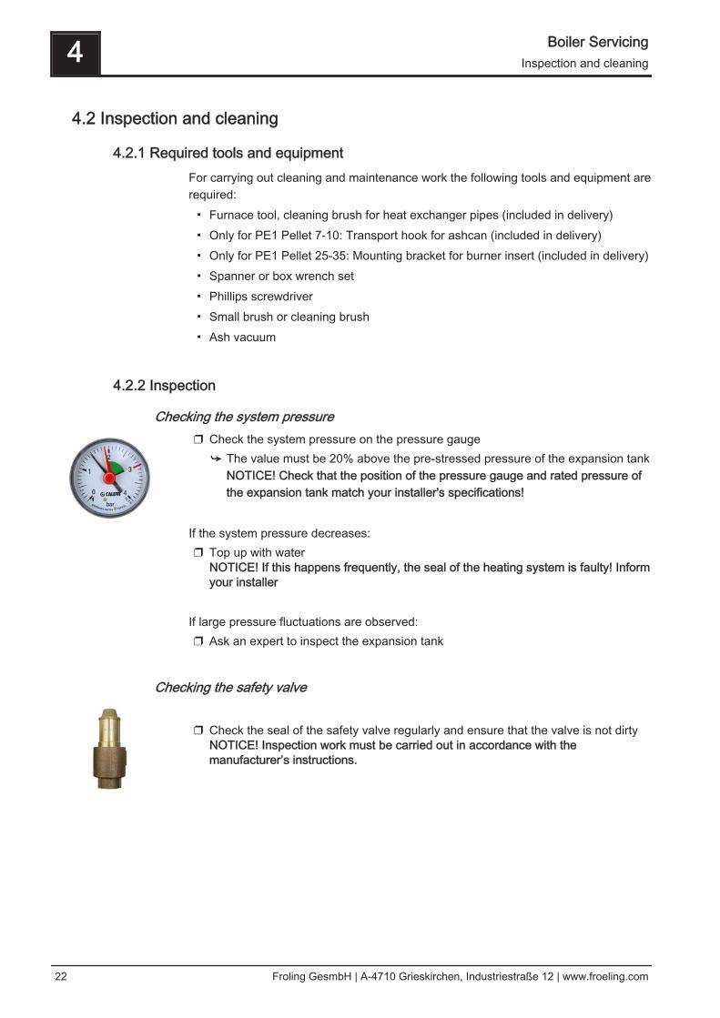
Checking the system pressure❒ Check the system pressure on the pressure gauge
➥ The value must be 20% above the pre-stressed pressure of the expansion tankNOTICE! Check that the position of the pressure gauge and rated pressure ofthe expansion tank match your installer's specifications!
If the system pressure decreases:❒ Top up with water
NOTICE! If this happens frequently, the seal of the heating system is faulty! Informyour installer
If large pressure fluctuations are observed:❒ Ask an expert to inspect the expansion tank
Checking the safety valve ❒ Check the seal of the safety valve regularly and ensure that the valve is not dirty
NOTICE! Inspection work must be carried out in accordance with themanufacturer’s instructions.
4 Boiler ServicingInspection and cleaning
22 Froling GesmbH | A-4710 Grieskirchen, Industriestraße 12 | www.froeling.com
4.2.3 CleaningThe ash drawer must be emptied at the correct interval according to energyrequirements and fuel quality. The grate, burn-out tray and combustion chambershould also be checked at these intervals.
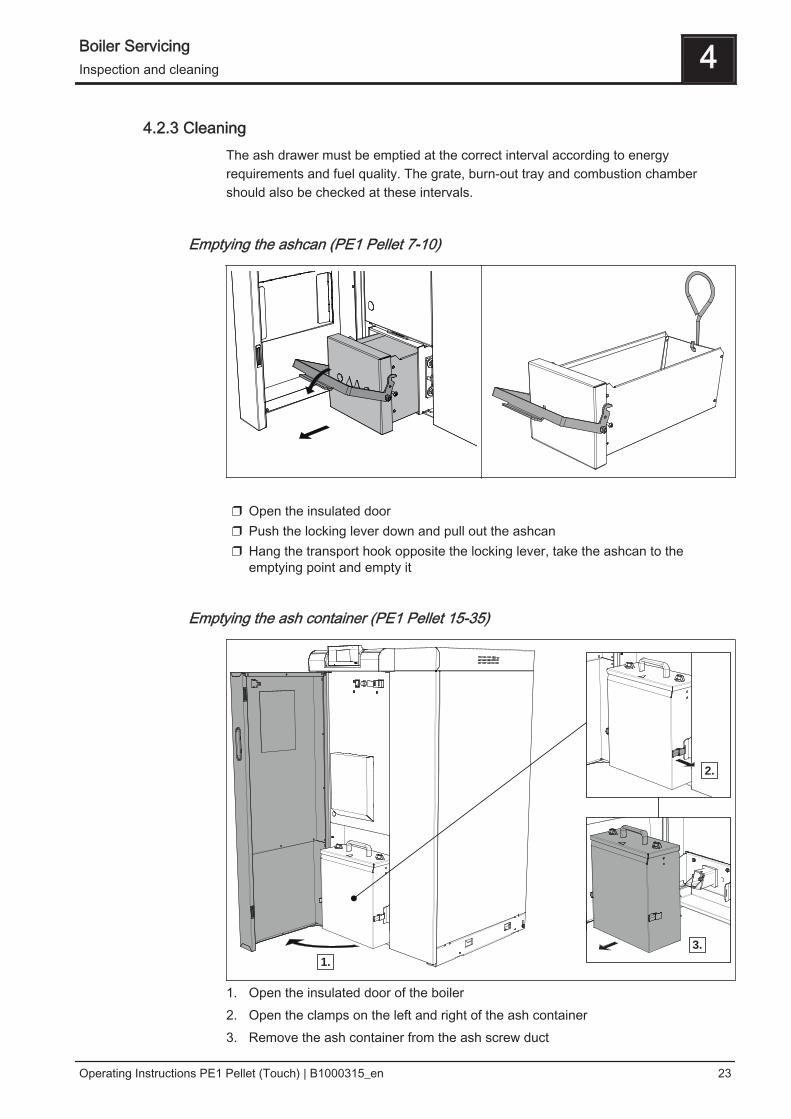
Emptying the ashcan (PE1 Pellet 7-10)
❒ Open the insulated door❒ Push the locking lever down and pull out the ashcan❒ Hang the transport hook opposite the locking lever, take the ashcan to the
emptying point and empty it
Emptying the ash container (PE1 Pellet 15-35)
1.
2.
3.
1. Open the insulated door of the boiler2. Open the clamps on the left and right of the ash container3. Remove the ash container from the ash screw duct
Boiler Servicing 4Inspection and cleaning
Operating Instructions PE1 Pellet (Touch) | B1000315_en 23
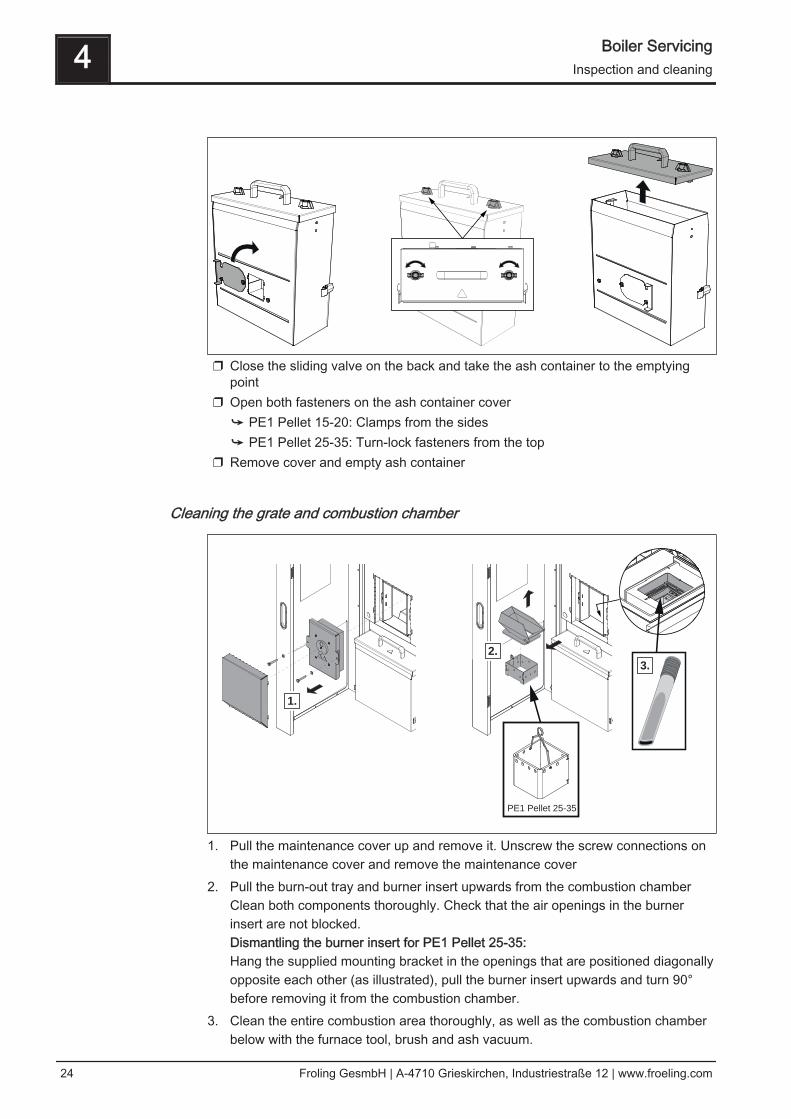
❒ Close the sliding valve on the back and take the ash container to the emptyingpoint
❒ Open both fasteners on the ash container cover➥ PE1 Pellet 15-20: Clamps from the sides➥ PE1 Pellet 25-35: Turn-lock fasteners from the top
❒ Remove cover and empty ash container
Cleaning the grate and combustion chamber
1.
2.
3.
PE1 Pellet 25-35
1. Pull the maintenance cover up and remove it. Unscrew the screw connections onthe maintenance cover and remove the maintenance cover
2. Pull the burn-out tray and burner insert upwards from the combustion chamberClean both components thoroughly. Check that the air openings in the burnerinsert are not blocked.Dismantling the burner insert for PE1 Pellet 25-35:Hang the supplied mounting bracket in the openings that are positioned diagonallyopposite each other (as illustrated), pull the burner insert upwards and turn 90°before removing it from the combustion chamber.
3. Clean the entire combustion area thoroughly, as well as the combustion chamberbelow with the furnace tool, brush and ash vacuum.
4 Boiler ServicingInspection and cleaning
24 Froling GesmbH | A-4710 Grieskirchen, Industriestraße 12 | www.froeling.com
4.2.4 Periodic inspection and cleaningThe boiler must be cleaned and inspected at appropriate intervals depending on theservice hours and fuel quality.Annual cleaning and inspection (1500 to 2000 service hours) is usually sufficient. Forfuels with a higher ash content (indicated by short emptying intervals for the ashcontainer), the work should be carried out more frequently.
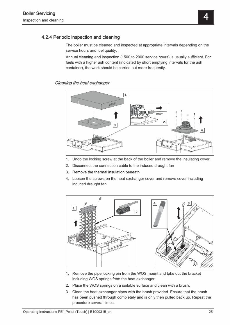
Cleaning the heat exchanger
1.
4.
2.3.
1. Undo the locking screw at the back of the boiler and remove the insulating cover.2. Disconnect the connection cable to the induced draught fan3. Remove the thermal insulation beneath4. Loosen the screws on the heat exchanger cover and remove cover including
induced draught fan
1.
2.
3.4.
1. Remove the pipe locking pin from the WOS mount and take out the bracketincluding WOS springs from the heat exchanger.
2. Place the WOS springs on a suitable surface and clean with a brush.3. Clean the heat exchanger pipes with the brush provided. Ensure that the brush
has been pushed through completely and is only then pulled back up. Repeat theprocedure several times.
Boiler Servicing 4Inspection and cleaning
Operating Instructions PE1 Pellet (Touch) | B1000315_en 25
4. Clean the flue gas collection chamber and the flue gas pipe opening using an ashvacuum. Take care not to damage the flue gas temperature sensor and thelambda probe.
Cleaning the flue gas pipe❒ Remove the inspection cover on the connecting pipe❒ Clean the connecting pipe between the boiler and chimney with a chimney
sweep's brush➥ Depending on the layout of the flue gas pipes and the chimney draught
cleaning, yearly may not be enough!
Checking the draught controller flap❒ Check that the draught controller flap moves freely
4.2.5 Inspection and cleaning the DHW tank unit (optional)The following tasks must only be carried out by a qualified technician. We recommenda yearly inspection / cleaning by Fröling customer services or by an authorised partner(third party maintenance) of Fröling Heizkessel- und Behälterbau GesmbH.
NOTICE
Unless otherwise stipulated by local regulations, perform all maintenance work fordrinking water systems in accordance with EN 1717 and EN 806.
Safety devices❒ Ensure the air outlet pipes on the safety valves are unobstructed❒ Check that the safety devices on the heating system work correctly and in
accordance with the manufacturer’s instructions❒ Check that the hot water and drinking water (if fitted) safety valves work correctly
and in accordance with the manufacturer’s instructions
Pressure reducing valve❒ Check any existing pressure reducing valve for wear and correct function in
accordance with the manufacturer's instructions
4 Boiler ServicingInspection and cleaning
26 Froling GesmbH | A-4710 Grieskirchen, Industriestraße 12 | www.froeling.com
Magnesium corrosion protection anodeThe magnesium corrosion protection anode protects the domestic water tank fromcorrosion and is therefore depleted over time, depending on the aggressiveness of thewater. It must therefore be replaced at regular intervals, so that the corrosionprotection is retained.NOTICE! If the magnesium corrosion protection anode is not replaced in good time, itcan lead to corrosion in the DHW tank. ❒ Check the magnesium corrosion protection anode initially after 2 years and then
annually in accordance with DIN 4753❒ Check the magnesium corrosion protection anode during the internal cleaning
⇨ See "Interior cleaning / removing limescale deposits" [page 27]❒ Check the magnesium corrosion protection anode for wear after removal of the
maintenance flange➥ In the case of wear (loss of material thickness to 1/3 of the original diameter)
the anode must be replaced
Interior cleaning / removing limescale depositsCheck the domestic hot water tank of the optional DHW tank unit annually forlimescale deposits, and clean if necessary: ❒ Close cold water supply line, release pressure in system and open drainage on
domestic hot water tank➥ Ensure it is vented by opening one of the valves in the drinking water supply
system❒ Remove the front cover of the DHW tank unit and maintenance flange of the
domestic water tank❒ Clean the domestic water tank inside with a jet of water
➥ If necessary, remove harder residues with a wooden spatula, cleaning brush orlimescale remover.
➥ Warning! Do not use sharp, metal tools. Do not use descaling agents.❒ Remove residual water or sludge residues with a wet vacuum❒ Wipe interior surfaces with a sponge or rag❒ Check magnesium protection anode and replace, if necessary
⇨ See "Magnesium corrosion protection anode" [page 27] ❒ When replacing, fit a new seal on maintenance flange
NOTICE! Rinse DHW tank before starting up again in accordance with EN 14336 ❒ Clean the outer parts with a wet cloth whenever necessary
➥ Avoid cleaning agents which are abrasive or contain solvents
Boiler Servicing 4Inspection and cleaning
Operating Instructions PE1 Pellet (Touch) | B1000315_en 27
4.3 Emissions measurement by chimney sweep or regulatory bodyVarious legal regulations stipulate that heating systems must be inspectedperiodically. In Germany this is regulated by the First Federal Emissions ProtectionOrdinance (BimSchV) in the last amended version, and in Austria by various statelaws. It is important to ensure that the boiler is clean and that there is adequate heatconsumption on the day of the measurement. (e.g. the storage tank must be able totake heat for the duration of the measurement).For further information and the procedure for measuring emissions, see the attachedcleaning instructions “Preparation for measuring emissions”.
4.4 Maintenance agreement / Customer serviceNOTICE! We recommend a yearly inspection by Froling customer services or anauthorised partner (third party maintenance).Regular maintenance and servicing by a heating specialist will ensure a long, trouble-free service life for your heating system. It will ensure that your system staysenvironmentally-friendly and operates efficiently and cost-effectively.In the course of this maintenance the entire system is inspected and optimised,particularly regulation and control of the boiler. The emission measurement carried outcan also be used to draw conclusions about the combustion performance of the boiler.For this reason, FROLING offers a service agreement, which optimises operatingsafety. Please see the details in the accompanying guarantee certificate.Your Froling customer service office will also be happy to advise you.
NOTICE
All national and regional regulations relating to regular testing of the system mustbe observed. Please be advised that, in Austria, commercial systems with a ratedheat output of 50 kW or more must be regularly tested at yearly intervals inaccordance with the Heating Plant Regulations (Feuerungsanlagen-Verordnung).
4.5 Replacement partsWith Froling original replacement parts in your boiler, you are using parts that matchperfectly. As the parts fit together so well, installation times are shortened and a longservice life is maintained.
NOTICE
Installing non-original parts will invalidate the guarantee.
❒ Only replace components or parts with original replacement parts
4 Boiler ServicingEmissions measurement by chimney sweep or regulatory body
28 Froling GesmbH | A-4710 Grieskirchen, Industriestraße 12 | www.froeling.com
4.6 Disposal information
4.6.1 Disposal of the ash❒ dispose of ash in accordance with the Waste Management Act (AWG)❒ dispose of ash in accordance with local regulations
4.6.2 Disposal of system components❒ Ensure that they are disposed of in an environmentally friendly way in accordance
with waste management regulations in the country (e.g. AWG in Austria)❒ You can separate and clean recyclable materials and send them to a recycling
centre.
Austria:Other countries:
Boiler Servicing 4Disposal information
Operating Instructions PE1 Pellet (Touch) | B1000315_en 29
5 Troubleshooting
5.1 General fault with power supply
Error characteristics Cause of error Elimination of error
Nothing is shown on thedisplayNo power to the controller
General power failureMain switch is turned offFI circuit breaker or lineprotection is switched offFaulty fuse in the controller
Turn on the main switchSwitch on the FI circuitbreaker or line protectionReplace the fuse – note theamperage (6.3AT)
5.1.1 Behaviour of system after a power failureWhen the power supply has been restored, the boiler returns to the previous modeand is controlled according to the specified program.❒ After a power failure, check whether the STL (high-limit thermostat) has tripped.❒ Keep the doors of the boiler closed during and after the power failure, at least until
the induced draught fan automatically starts up again.EXCEPTION:If the boiler operating status was "Heating up", "Pre-heating" or "Ignition" before thepower failure, the boiler follows the shutdown procedure and cleaning commences.Only then does the boiler switch to "Preparation" operating status and the systemstarts up again.
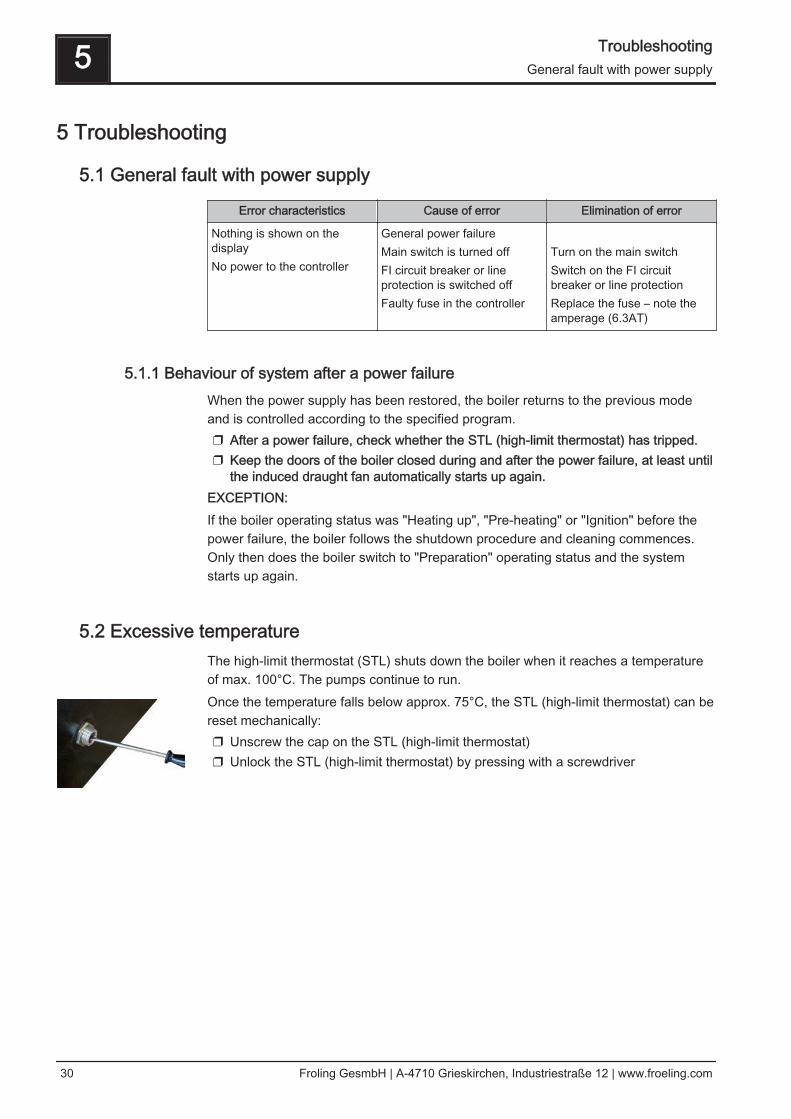
5.2 Excessive temperatureThe high-limit thermostat (STL) shuts down the boiler when it reaches a temperatureof max. 100°C. The pumps continue to run.Once the temperature falls below approx. 75°C, the STL (high-limit thermostat) can bereset mechanically:❒ Unscrew the cap on the STL (high-limit thermostat)❒ Unlock the STL (high-limit thermostat) by pressing with a screwdriver
5 TroubleshootingGeneral fault with power supply
30 Froling GesmbH | A-4710 Grieskirchen, Industriestraße 12 | www.froeling.com
5.3 Faults with fault message
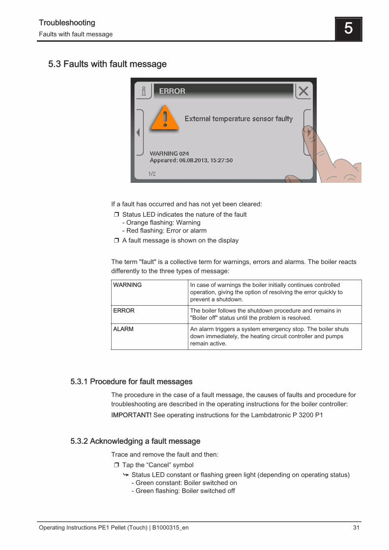
If a fault has occurred and has not yet been cleared:❒ Status LED indicates the nature of the fault
- Orange flashing: Warning- Red flashing: Error or alarm
❒ A fault message is shown on the display The term "fault" is a collective term for warnings, errors and alarms. The boiler reactsdifferently to the three types of message:
WARNING In case of warnings the boiler initially continues controlledoperation, giving the option of resolving the error quickly toprevent a shutdown.
ERROR The boiler follows the shutdown procedure and remains in"Boiler off" status until the problem is resolved.
ALARM An alarm triggers a system emergency stop. The boiler shutsdown immediately, the heating circuit controller and pumpsremain active.
5.3.1 Procedure for fault messagesThe procedure in the case of a fault message, the causes of faults and procedure fortroubleshooting are described in the operating instructions for the boiler controller:IMPORTANT! See operating instructions for the Lambdatronic P 3200 P1
5.3.2 Acknowledging a fault messageTrace and remove the fault and then:❒ Tap the “Cancel” symbol
➥ Status LED constant or flashing green light (depending on operating status)- Green constant: Boiler switched on- Green flashing: Boiler switched off
Troubleshooting 5Faults with fault message
Operating Instructions PE1 Pellet (Touch) | B1000315_en 31
6 Appendix
6.1 Addresses
6.1.1 Address of manufacturer
FRÖLINGHeizkessel- und Behälterbau GesmbH Industriestraße 12A-4710 GrieskirchenAUSTRIA TEL 0043 (0)7248 606 0FAX 0043 (0)7248 606 600INTERNET www.froeling.com
6.1.2 Address of the installer
Stamp
6 AppendixAddresses
32 Froling GesmbH | A-4710 Grieskirchen, Industriestraße 12 | www.froeling.com