PDRP-8550-SP-0012_REV_F2.pdf
20
-
Upload
rashmi-ranjan-mohanty -
Category
Documents
-
view
85 -
download
6
description
Instrument details
Transcript of PDRP-8550-SP-0012_REV_F2.pdf
PARADIP REFINERY PROJECT FUNCTIONAL SPECIFICATION
INSTRUMENT / ELECTRICAL INTERFACE STANDARD
A
PDRP-8550-SP-0012 PAGE 2 OF 20
REV F2
DSN 1983
CONTENTS
SECTION SUBJECT 1.0 INTRODUCTION .................................................................................. 3 1.1 ABBREVIATIONS & DEFINITIONS..................................................... 3 1.2 REFERENCE DOCUMENTS ............................................................... 3 2.0 INSTRUMENT / ELECTRICAL CONTROL INTERFACE .................... 4 2.1 SIGNALS FROM INSTRUMENT TO ELECTRICAL............................ 4 2.2 SIGNALS FROM ELECTRICAL TO INSTRUMENT............................ 5 2.3 INTELLIGENT MOTOR CONTROL SYSTEM ..................................... 5 2.4 CONTROL SIGNALS ........................................................................... 5 2.5 PROTECTIVE SYSTEM SIGNALS ...................................................... 6 2.6 ELECTRICAL ALARMS AND STATUS SIGNALS ............................. 6 2.7 CABLE INTERFACE PHILOSOPHY ................................................... 6 3.0 UNINTERRUPTABLE POWER SUPPLIES (UPS) .............................. 6 4.0 EARTHING........................................................................................... 7 5.0 ELECTRIC TRACING OF INSTRUMENT............................................ 7 6.0 MOTOR OPERATED VALVES ............................................................ 7 7.0 INTERFACE CATEGORIES ................................................................ 8 ATTACHMENTS ATTACHMENT 1 SIGNAL TYPES ATTACHMENT 2 MOTOR CONTROLS BLOCK DIAGRAM

PARADIP REFINERY PROJECT FUNCTIONAL SPECIFICATION
INSTRUMENT / ELECTRICAL INTERFACE STANDARD
A
PDRP-8550-SP-0012 PAGE 3 OF 20
REV F2
DSN 1983
1.0 INTRODUCTION
This specification defines the interface requirement between the Instrument Systems and Electrical Systems for the Paradip Refinery Project. The project is a 15 MMTPA grassroots refinery complex located at a site 5 Km south of the Port of Paradip in the state of Orissa, on the northern part of the east coast of India.
1.1 ABBREVIATIONS & DEFINITIONS
Abbreviation Description DCS Distributed Control System DCU Data Concentrator Unit Electrical Systems Include MCC, Switchgear and IMCS. ESD Emergency Shutdown System FDAS Fire Detection and Alarm System GDS Gas Detection System HV High Voltage (> 1000V) IMCS Intelligent Motor Control System Instrument Systems Includes the DCS, ESD, FDAS and GDS IRP Interposing Relay Panel LV Low Voltage (≤ 1000V) MCC Motor Control Centre MOV Motor Operated Valve PLC Programmable Logic Control System PMS Power Management System RCU Remote Control Unit SIL Safety Integrity Level SRR Satellite Rack Room UPS Uninterruptible Power Supply VSD Variable Speed Drive
Table 1: Abbreviations
1.2 REFERENCE DOCUMENTS Project Standards and Specifications
Document Number Title PDRP-8531-SP-0001 Electrical Standard
PDRP-8531-SP-0016 Electrical Requirements in Package Supply Equipments Units
PDRP-8550-SP-0001 Instrumentation for General Hydrocarbon and Utility Services
PDRP-8550-SP-0006 Instrumentation for Packaged Units PDRP-8550-SP-0002 Instrument Cable Standard
PARADIP REFINERY PROJECT FUNCTIONAL SPECIFICATION
INSTRUMENT / ELECTRICAL INTERFACE STANDARD
A
PDRP-8550-SP-0012 PAGE 4 OF 20
REV F2
DSN 1983
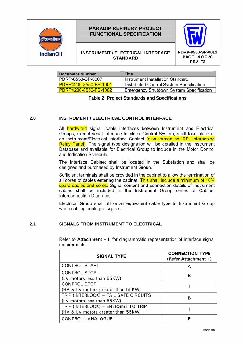
Document Number Title PDRP-8550-SP-0007 Instrument Installation Standard PDRP4200-8550-FS-1001 Distributed Control System Specification PDRP4200-8550-FS-1002 Emergency Shutdown System Specification
Table 2: Project Standards and Specifications
2.0 INSTRUMENT / ELECTRICAL CONTROL INTERFACE
All hardwired signal /cable interfaces between Instrument and Electrical Groups, except serial interface to Motor Control System, shall take place at an Instrument/Electrical Interface Cabinet (also termed as IRP -Interposing Relay Panel). The signal type designation will be detailed in the Instrument Database and available for Electrical Group to include in the Motor Control and Indication Schedule.
The Interface Cabinet shall be located in the Substation and shall be designed and purchased by Instrument Group.
Sufficient terminals shall be provided in the cabinet to allow the termination of all cores of cables entering the cabinet. This shall include a minimum of 10% spare cables and cores. Signal content and connection details of Instrument cables shall be included in the Instrument Group series of Cabinet Interconnection Diagrams.
Electrical Group shall utilise an equivalent cable type to Instrument Group when cabling analogue signals.
2.1 SIGNALS FROM INSTRUMENT TO ELECTRICAL
Refer to Attachment – I, for diagrammatic representation of interface signal requirements.
SIGNAL TYPE CONNECTION TYPE (Refer Attachment I )
CONTROL START A CONTROL STOP (LV motors less than 55KW) B
CONTROL STOP (HV & LV motors greater than 55KW) I
TRIP (INTERLOCK) – FAIL SAFE CIRCUITS (LV motors less than 55KW) B
TRIP (INTERLOCK) – ENERGISE TO TRIP (HV & LV motors greater than 55KW) I
CONTROL - ANALOGUE E
PARADIP REFINERY PROJECT FUNCTIONAL SPECIFICATION
INSTRUMENT / ELECTRICAL INTERFACE STANDARD
A
PDRP-8550-SP-0012 PAGE 5 OF 20
REV F2
DSN 1983
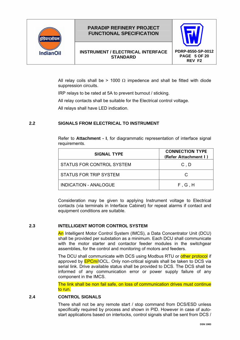
All relay coils shall be > 1000 Ω impedence and shall be fitted with diode suppression circuits.
IRP relays to be rated at 5A to prevent burnout / sticking.
All relay contacts shall be suitable for the Electrical control voltage.
All relays shall have LED indication.
2.2 SIGNALS FROM ELECTRICAL TO INSTRUMENT
Refer to Attachment - I, for diagrammatic representation of interface signal requirements.
SIGNAL TYPE CONNECTION TYPE (Refer Attachment I )
STATUS FOR CONTROL SYSTEM C , D
STATUS FOR TRIP SYSTEM C
INDICATION - ANALOGUE F , G , H
Consideration may be given to applying Instrument voltage to Electrical contacts (via terminals in Interface Cabinet) for repeat alarms if contact and equipment conditions are suitable.
2.3 INTELLIGENT MOTOR CONTROL SYSTEM An Intelligent Motor Control System (IMCS), a Data Concentrator Unit (DCU) shall be provided per substation as a minimum. Each DCU shall communicate with the motor starter and contactor feeder modules in the switchgear assemblies, for the control and monitoring of motors and feeders.
The DCU shall communicate with DCS using Modbus RTU or other protocol if approved by EPCm/IOCL. Only non-critical signals shall be taken to DCS via serial link. Drive available status shall be provided to DCS. The DCS shall be informed of any communication error or power supply failure of any component in the IMCS.
The link shall be non fail safe, on loss of communication drives must continue to run.
2.4 CONTROL SIGNALS There shall not be any remote start / stop command from DCS/ESD unless specifically required by process and shown in PID. However in case of auto-start applications based on interlocks, control signals shall be sent from DCS /

PARADIP REFINERY PROJECT FUNCTIONAL SPECIFICATION
INSTRUMENT / ELECTRICAL INTERFACE STANDARD
A
PDRP-8550-SP-0012 PAGE 6 OF 20
REV F2
DSN 1983
ESD to MCC. These signals shall be hardwired via Interposing Relay Panel (IRP) in substations.
2.5 PROTECTIVE SYSTEM SIGNALS All signals between ESD and motor starters shall be hardwired via Interposing Relay Panel (IRP).
Critical functions such as pump auto-start, filter sequencing etc. to be implemented in ESD. Definition of what is critical shall be determined from criticality review and shall be shown in C&E diagrams.
If motor running signal is hardwired to ESD, stop output (ESD DO) shall be fed back as an ESD input (ESD DI) to ensure SOE records in correct time order.
2.6 ELECTRICAL ALARMS AND STATUS SIGNALS All alarms and status signals generated by electrical equipment like circuit breakers shall be communicated to DCS.
2.7 CABLE INTERFACE PHILOSOPHY
All electrical and instrument hardwired interfaces shall be through interposing relay cabinets located in substations. IRP local power requirements to be provided by Electrical discipline.
The laying and termination at both ends, of the cable between the IRP and the MCC shall be the responsibility of Electrical discipline.
The laying and termination at both ends, of the cable between the IRP and the DCS / ESD, shall be the responsibility of instrument discipline.
3.0 UNINTERRUPTABLE POWER SUPPLIES (UPS)
Electrical Group shall provide dual redundant UPS supplies. For further details refer to Project specification PDRP-8531-SP-0006 (AC uninterruptible power system (UPS).
The voltage shall be Single Phase and neutral 110 VAC 50Hz.
These supplies shall be cabled to Instrument Power Distribution Cabinets located in each control building, SRR and other building locations where required to power the control, monitoring and safety systems.
The UPS feeders shall be arranged such that the maximum fuse size for any feeder shall not be more than 20% capacity of the UPS rating or 100Amp which ever is lower.
The supply and installation of the feeder cables from the UPS or Non maintained distribution boards to the Instrument Power Distribution Cabinet shall be the responsibility of the Electrical Group.
Instrument power supplies within Analyser Houses shall be derived from the incoming 3 phase feeder supplied and installed by Electrical Group.

PARADIP REFINERY PROJECT FUNCTIONAL SPECIFICATION
INSTRUMENT / ELECTRICAL INTERFACE STANDARD
A
PDRP-8550-SP-0012 PAGE 7 OF 20
REV F2
DSN 1983
Where an Analyser is required to have a UPS supply this shall be supplied and installed by Instrument Group from Instrument Power Distribution Board in nearest SRR.
UPS voltages and failure alarms shall be connected to DCS and made available to operator in control rooms
4.0 EARTHING
In the field, Instrument Group shall provide and install the earth links from cable ladder/tray, junction boxes, frames and instruments to strategically located earth bars supplied and installed by Electrical Group. These earth bars shall be connected to Safety Earth only.
In Control Rooms and SRR’s, Instrument Group shall provide and install earth links from cabinets, consoles and other instrument equipment to strategically located underfloor earth bars supplied and installed by Electrical Group. Separate earth bars shall be provided for Safety Earth (SE), Instrument Clean Earth (ICE), and Intrinsically Safe Earth (ISE).
For details refer to PDRP-8550-63-0001, Instrument Earthing Philosophy Diagram.
5.0 ELECTRIC TRACING OF INSTRUMENT
All electric tracing of instruments shall be carried out by Instrument Group utilising pre-traced instrument tubing bundles.
Instruments which require electric tracing are detailed in the Instrument Index Database and PDRP-8550-SP-0010 Protection of Instruments.
Instrument Group shall advise Electrical Group of all connections required to pre-traced bundles and the length of each bundle to enable power requirements and connections to power junction boxes to be designated.
6.0 MOTOR OPERATED VALVES
Motor operated valves shall be powered by Electrical group from their LV switch boards. Normally the power supply to the MOV shall be 415V 50 Hz 3-phase.
The valves can be operated from field as well as from DCS.
Where MOV’s are networked (typically for offsites and tank farms) their network module shall be mounted in SRR cabinets and interfaced to the DCS through redundant serial MODBUS links.

PARADIP REFINERY PROJECT FUNCTIONAL SPECIFICATION
INSTRUMENT / ELECTRICAL INTERFACE STANDARD
A
PDRP-8550-SP-0012 PAGE 8 OF 20
REV F2
DSN 1983
7.0 INTERFACE CATEGORIES
Interface Categories shown in Attachment - II shall be used to interface with electrical equipment. Referenced signal types are detailed in Attachment – I in line with clause 2.1 and 2.2.
The signals to be interfaced between Electrical System and Instrument System shall be as defined by process and shown in PIDs. Motor Control Block Diagrams in Attachment II provides the guideline to implement those requirements in a consistent manner throughout the refinery.
Deviation from the attached categories or any additional requirements shall require approval from IOCL and this document shall be updated accordingly.

PARADIP REFINERY PROJECT FUNCTIONAL SPECIFICATION
INSTRUMENT / ELECTRICAL INTERFACE STANDARD
A
PDRP-8550-SP-0012 PAGE 9 OF 20
REV F2
DSN 1983
ATTACHMENT I
SIGNAL TYPES The following signal types shall be used to interface with the electrical system.
• A Start • B Stop (fail safe) • C Status Indication • D Status Indication • E 4-20 mA Control • F 4-20 mA Indication (DCS/ESD source) • G 4-20 mA Indication (DCS/ESD sink) • H 4-20 mA Indication / Control (MCC powered, non-isolated) • I Stop (non fail safe)
Any deviations from the above signal types or additional requirement shall require approval from IOCL and this document will be updated accordingly.

PARADIP REFINERY PROJECT FUNCTIONAL SPECIFICATION
INSTRUMENT / ELECTRICAL INTERFACE STANDARD
A
PDRP-8550-SP-0012 PAGE 10 OF 20
REV F2
DSN 1983
Electrical / Instrument Interface Schematics
CONTACT CLOSES TO STOP
R
INST.ELECT
MCC CONTROL VOLTAGE
24VDC
2 sec
START
TYPE A
CONTACT CLOSES TO START
MCC CONTROL VOLTAGE R
INSTELECT.
24 VDC
2 secs
STOP
TYPE B
CONTACT OPENS TO STOP
MCC CONTROL VOLTAGE MAINTAINED SIGNAL
R
INSTELECT.
TYPE C
STATUS 24 VDC
PARADIP REFINERY PROJECT FUNCTIONAL SPECIFICATION
INSTRUMENT / ELECTRICAL INTERFACE STANDARD
A
PDRP-8550-SP-0012 PAGE 11 OF 20
REV F2
DSN 1983
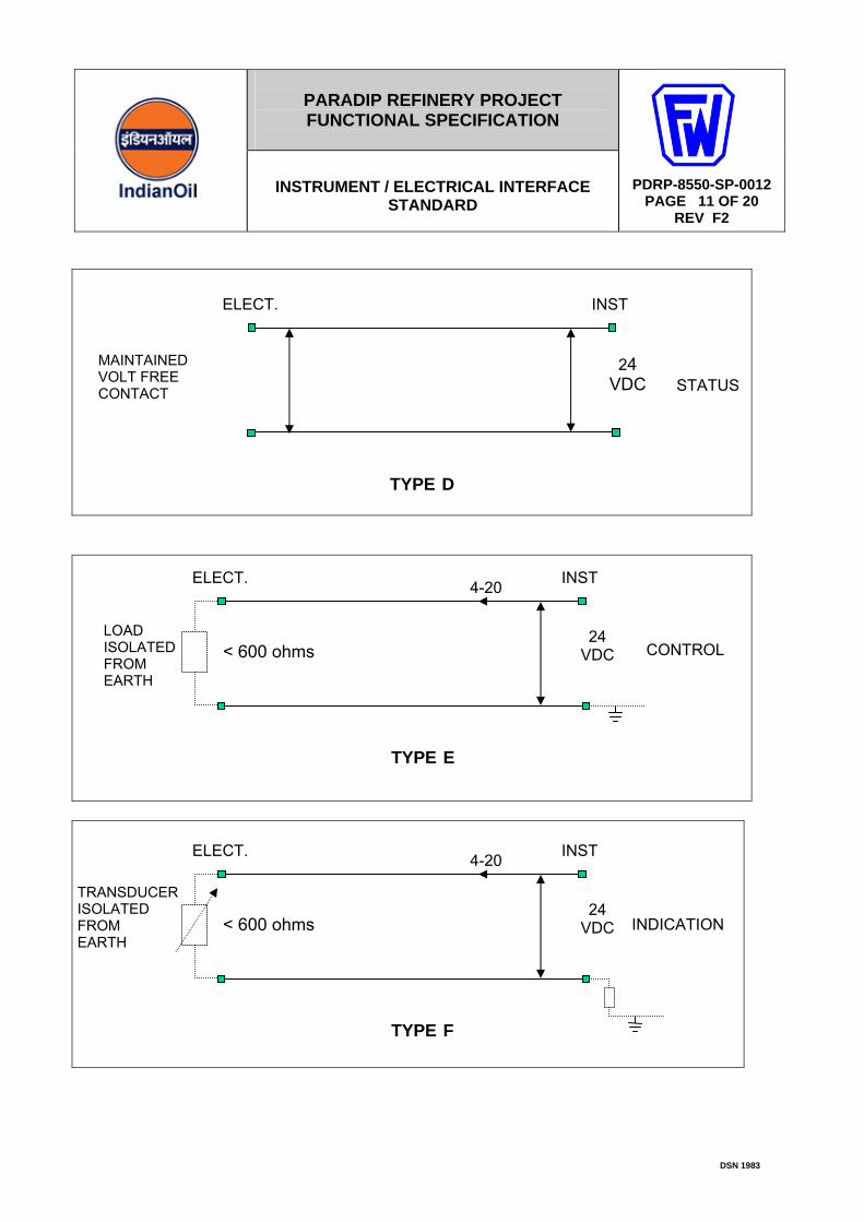
INSTELECT.
TYPE D
STATUS24
VDC MAINTAINED VOLT FREE CONTACT
INSTELECT.
TYPE E
CONTROL24
VDC LOAD ISOLATED FROM EARTH
4-20
< 600 ohms
INSTELECT.
TYPE F
INDICATION 24
VDC
TRANSDUCER ISOLATED FROM EARTH
4-20
< 600 ohms

PARADIP REFINERY PROJECT FUNCTIONAL SPECIFICATION
INSTRUMENT / ELECTRICAL INTERFACE STANDARD
A
PDRP-8550-SP-0012 PAGE 12 OF 20
REV F2
DSN 1983
MCC CONTROL VOLTAGE
2 secs
INSTELECT.
TYPE G
SOURCE ISOLATED FROM EARTH
4-20
24 VDC
INSTELECT.
TYPE H
INDICATION 24 VDC
EARTHED OUTPUT FROM MCC
4-20
ISOLATOR
4-20
24 VDC
R
INSTELECT.
24 VDC
STOP
TYPE I
CONTACT CLOSES TO STOP

PARADIP REFINERY PROJECT FUNCTIONAL SPECIFICATION
INSTRUMENT / ELECTRICAL INTERFACE STANDARD
A
PDRP-8550-SP-0012 PAGE 13 OF 20
REV F2
DSN 1983
ATTACHMENT – II
MOTOR CONTROLS BLOCK DIAGRAM Typical motor controls block diagrams below:
M1 Low Voltage Fixed-speed Motors (Critical) M2 Low Voltage Fixed-speed Motors (Non-Critical) M3 Fixed Speed LV Drive with ESD Trip & Auto Start from ESD M4 Fixed Speed LV Drive with ESD Trip & Auto Start from DCS M5 Fixed Speed HV Drives M6 Variable Speed Drives H1 Heaters
Interface categories defined in this document shall be followed to maintain a consistent interface procedure throughout the refinery. Deviation from the attached categories or any additional requirements shall require approval from IOCL and this document shall be updated accordingly.
PARADIP REFINERY PROJECT FUNCTIONAL SPECIFICATION
INSTRUMENT / ELECTRICAL INTERFACE STANDARD
A
PDRP-8550-SP-0012 PAGE 14 OF 20
REV F2
DSN 1983
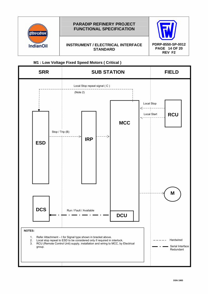
M1 : Low Voltage Fixed Speed Motors ( Critical )
Serial Interface Redundant
IRP
M
SRR SUB STATION FIELD
ESD
MCC
RCU
DCU
DCS
Stop / Trip (B)
Run / Fault / Available
Local Stop
NOTES:
1. Refer Attachment – I for Signal type shown in bracket above. 2. Local stop repeat to ESD to be considered only if required in interlock. 3. RCU (Remote Control Unit) supply, installation and wiring to MCC, by Electrical
group.
Local Stop repeat signal ( C ) (Note 2)
Local Start
Hardwired
PARADIP REFINERY PROJECT FUNCTIONAL SPECIFICATION
INSTRUMENT / ELECTRICAL INTERFACE STANDARD
A
PDRP-8550-SP-0012 PAGE 15 OF 20
REV F2
DSN 1983
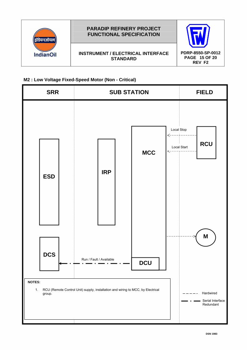
M2 : Low Voltage Fixed-Speed Motor (Non - Critical)
IRP
M
SRR SUB STATION FIELD
ESD
MCC
RCU
DCU
DCS Run / Fault / Available
Local Stop
NOTES: 1. RCU (Remote Control Unit) supply, installation and wiring to MCC, by Electrical
group.
Local Start
Serial Interface Redundant
Hardwired
PARADIP REFINERY PROJECT FUNCTIONAL SPECIFICATION
INSTRUMENT / ELECTRICAL INTERFACE STANDARD
A
PDRP-8550-SP-0012 PAGE 16 OF 20
REV F2
DSN 1983
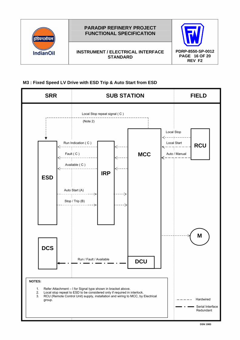
M3 : Fixed Speed LV Drive with ESD Trip & Auto Start from ESD
IRP
M
SRR SUB STATION FIELD
ESD
MCC
RCU
DCU
DCS
Run / Fault / Available
Run Indication ( C )
Fault ( C )
Auto Start (A)
Available ( C )
Stop / Trip (B)
NOTES:
1. Refer Attachment – I for Signal type shown in bracket above. 2. Local stop repeat to ESD to be considered only if required in interlock. 3. RCU (Remote Control Unit) supply, installation and wiring to MCC, by Electrical
group.
Serial Interface Redundant
Hardwired
Local Stop
Local Start
Local Stop repeat signal ( C ) (Note 2)
Auto / Manual

PARADIP REFINERY PROJECT FUNCTIONAL SPECIFICATION
INSTRUMENT / ELECTRICAL INTERFACE STANDARD
A
PDRP-8550-SP-0012 PAGE 17 OF 20
REV F2
DSN 1983
M4 : Fixed Speed LV Drive with ESD Trip & Auto Start from DCS
Serial Interface Redundant
IRP
M
SRR SUB STATION FIELD
ESD
MCC
RCU
DCU
DCS
Run / Fault / Available
Local Stop
Auto Start (A)
Local Start Stop / Trip (B)
NOTES:
1. Refer Attachment – I for Signal type shown in bracket above. 2. Local stop repeat to ESD to be considered only if required in interlock. 3. RCU (Remote Control Unit) supply, installation and wiring to MCC, by Electrical
group. 4. The DCS and ESD stop signals may be connected in series at IRP to provide single
stop input at MCC.
Hardwired
Local Stop repeat signal ( C ) (Note 2)
Auto / Manual
Stop (B)
PARADIP REFINERY PROJECT FUNCTIONAL SPECIFICATION
INSTRUMENT / ELECTRICAL INTERFACE STANDARD
A
PDRP-8550-SP-0012 PAGE 18 OF 20
REV F2
DSN 1983
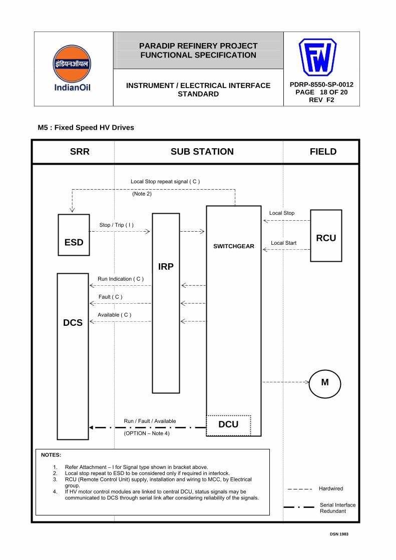
M5 : Fixed Speed HV Drives
IRP
M
SRR SUB STATION FIELD
ESD
SWITCHGEAR
RCU
DCS
Local Stop
Run Indication ( C )
Fault ( C )
Available ( C )
Local Start
Stop / Trip ( I )
NOTES:
1. Refer Attachment – I for Signal type shown in bracket above. 2. Local stop repeat to ESD to be considered only if required in interlock. 3. RCU (Remote Control Unit) supply, installation and wiring to MCC, by Electrical
group. 4. If HV motor control modules are linked to central DCU, status signals may be
communicated to DCS through serial link after considering reliability of the signals.
Hardwired
Local Stop repeat signal ( C ) (Note 2)
DCU Run / Fault / Available (OPTION – Note 4)
Serial Interface Redundant
PARADIP REFINERY PROJECT FUNCTIONAL SPECIFICATION
INSTRUMENT / ELECTRICAL INTERFACE STANDARD
A
PDRP-8550-SP-0012 PAGE 19 OF 20
REV F2
DSN 1983
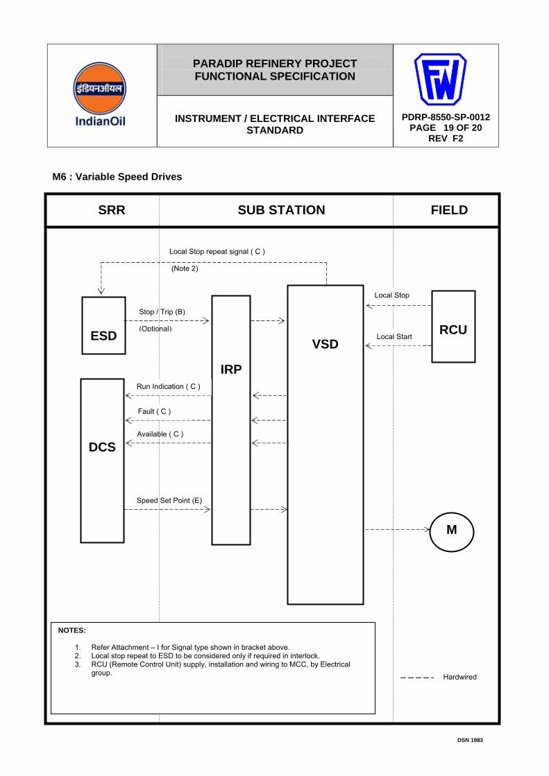
M6 : Variable Speed Drives
IRP
M
SRR SUB STATION FIELD
ESD
VSD
RCU
DCS
Local Stop
Run Indication ( C )
Fault ( C )
Speed Set Point (E)
Local Start
Stop / Trip (B) (Optional)
NOTES:
1. Refer Attachment – I for Signal type shown in bracket above. 2. Local stop repeat to ESD to be considered only if required in interlock. 3. RCU (Remote Control Unit) supply, installation and wiring to MCC, by Electrical
group. Hardwired
Available ( C )
Local Stop repeat signal ( C ) (Note 2)

PARADIP REFINERY PROJECT FUNCTIONAL SPECIFICATION
INSTRUMENT / ELECTRICAL INTERFACE STANDARD
A
PDRP-8550-SP-0012 PAGE 20 OF 20
REV F2
DSN 1983
H1 : Heaters
IRP
SRR SUB STATION FIELD
ESD
MCC
DCS
Stop (B) Note 3
Stop / Trip (B)
NOTES:
1. Refer Attachment – I for Signal type shown in bracket above. 2. The DCS and ESD stop signals may be connected in series at IRP to provide single
stop input at MCC. 3. Only if shown in PID.
Start (A) Note 3
HEATER
DCU
Serial Interface Redundant
Hardwired
Run / Fault / Available