Products for Underground Network and Residential...
78
BURNDY ® Canada: 1-800-387-6487 www.burndy.com US: 1-800-346-4175 Underground K-1 Products for Underground Network and Residential Distribution Systems TABLE OF CONTENTS K-3 K-4 K-5 K-8 K-9 to K-31 K-31 to K-36 K-37 K-37, K-38 K-39, K-40 K-41 to K-61 K-62 to K-63 Underground Network Distribution Products Technical Data: Underground System Connection and Protection Types of BURNDY ® Underground Connectors & Accessories MOLE™ Multiple Outlet Connectors Technical Data How to order your BURNDY ® MOLE™ MOLE™ Types MOLE™ Accessories HYCRAB™ Technical Data HYCRAB™ and Accessories Limiters Technical Data Limiters and Accessories High Capacity Limiter K-64 K-65 K-65 K-66 K-67 K-68 K-69 K-69 K-70 to K-72 K-73 K-74 K-75 K-76 K-77 K-78 Underground Residential Distribution Products MOLE™ Types RDMD-28G, RDMD2858D, RDMD-28CR Types RDM-28, RDM-28T MOLE™ Tap Kits Types RA6UC-SL, RA6UCR-SL (URD Street Lighting Tap Kit) Types RYA-UC, RYA-AC, RYA-UCR, RYA-ACR Overhead or Underground Secondary Connectors Type BSSBC Submersible Secondary Connectors Types BSSBC, BDESS URD Insulated Splice Kit Type YS-CG Y-LOK HYREDUCER™ Splices Type YRB-U Type YRB-T Submersible Splice Covers Types BSSI, BTWTC Service Taps and Terminals Types K-P-C, YPC-C Types K6B, K33B Types F-A, K6A34U, K-P-UC Power Distribution Blocks Types BPD, BPD2
Transcript of Products for Underground Network and Residential...
BURNDY®
Canada: 1-800-387-6487 www.burndy.com US: 1-800-346-4175
Underground
K-1
Products for Underground Network and Residential Distribution SystemsTABLE OF CONTENTS
K-3
K-4
K-5K-8
K-9 to K-31
K-31 to K-36
K-37
K-37, K-38
K-39, K-40
K-41 toK-61
K-62 toK-63
Underground Network Distribution Products
Technical Data:Underground System Connection and Protection
Types of BURNDY® Underground Connectors & Accessories
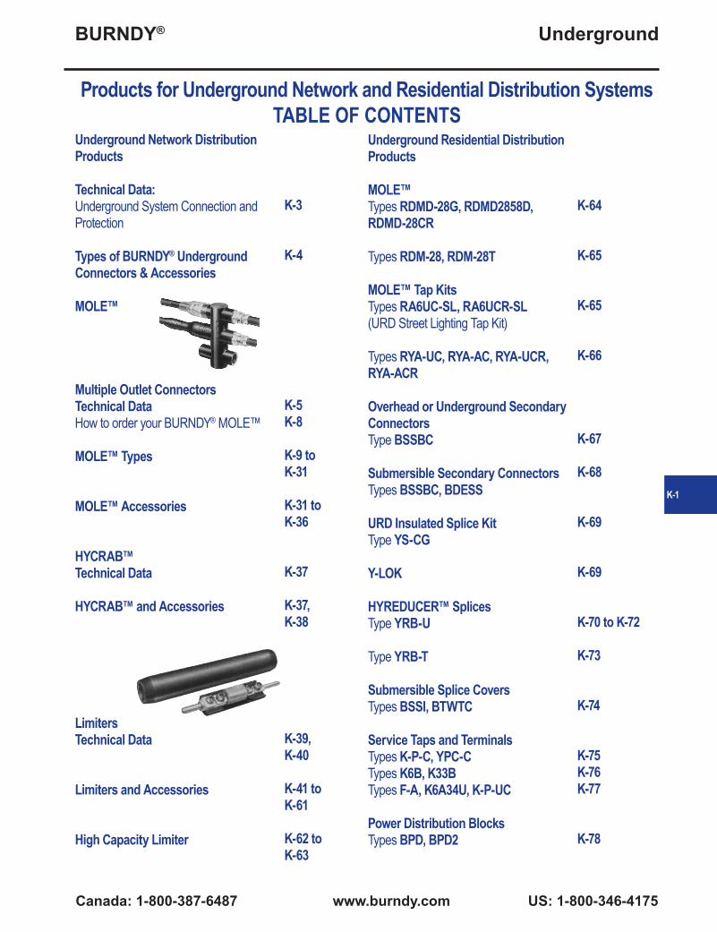
MOLE™
Multiple Outlet ConnectorsTechnical DataHow to order your BURNDY® MOLE™
MOLE™ Types
MOLE™ Accessories
HYCRAB™Technical Data
HYCRAB™ and Accessories
LimitersTechnical Data
Limiters and Accessories
High Capacity Limiter
K-64
K-65
K-65
K-66
K-67
K-68
K-69
K-69
K-70 to K-72
K-73
K-74
K-75K-76K-77
K-78
Underground Residential Distribution Products
MOLE™Types RDMD-28G, RDMD2858D, RDMD-28CR
Types RDM-28, RDM-28T
MOLE™ Tap KitsTypes RA6UC-SL, RA6UCR-SL(URD Street Lighting Tap Kit)
Types RYA-UC, RYA-AC, RYA-UCR, RYA-ACR
Overhead or Underground Secondary ConnectorsType BSSBC
Submersible Secondary ConnectorsTypes BSSBC, BDESS
URD Insulated Splice KitType YS-CG
Y-LOK
HYREDUCER™ SplicesType YRB-U
Type YRB-T
Submersible Splice CoversTypes BSSI, BTWTC
Service Taps and TerminalsTypes K-P-C, YPC-CTypes K6B, K33BTypes F-A, K6A34U, K-P-UC
Power Distribution BlocksTypes BPD, BPD2

BURNDY®
US: 1-800-346-4175 www.burndy.com Canada: 1-800-387-6487
Underground
K-2
Products for Underground Network Distribution SystemsTABLE OF CONTENTS
K-9K-10K-11K-12K-13K-14
K-15K-16K-17K-18K-19K-20
K-21K-22K-23K-24K-25K-26
K-27, K-28K-29K-30K-31
K-31
K-32
K-33, K34
K-35
MOLE™
1500 AMP Type ZM Type ZMT Type ZME Type ZML Type ZMX Type ZMK
2000-2500 AMP Type ZM Type ZMT Type ZME Type ZML Type ZMX Type ZMK
3000 AMP Type ZM Type ZMT Type ZME Type ZML Type ZMX Type ZMK
MOLE™ Stud Connectors Type ZMLDN Type Z2MLDN Type ZMDN Type ZMTDN
MOLE™ Outlet Plugs Type Z-P
Socket and Nut Assembly Type Z-NR
MOLE™ Compression Cone Type Z
MOLE™ Coupler Type ZMS
K-35K-36
K-37K-38
K-41K-42K-43K-43K-44K-45K-46K-47K-48K-48K-49K-49K-50K-50K-51K-52K-53K-54K-54K-55K-56K-56
K-57
K-58
MOLE™ Sleeves Type CM (NOTAPE™) Type Z-C (Outlet Insulating Sleeve)
HYCRAB™ Type ZM Type YNM
Limiters Type YFS-CR, YFS-CP Type YFS-CPL Type YFSR, YFSP Type YFSP-L Type YFA-CR, YFA-CP Type YFA-CPL Types YFAR, YFAP Type YFAP-L Types YFM-CR, YFM-CP Type YFM-CPL Types YFMR, YFMP Type YFMP-L Type VYFT Type NYFT Type LYS Type LYM Type LF Type LYBASE Type LYS34P2 Type LYS-P5 Type LYM34P3 Type LYS-P6
Network Protector Fuses Type Y, Z
T-Connector Type NYT
BURNDY®
Canada: 1-800-387-6487 www.burndy.com US: 1-800-346-4175
Underground
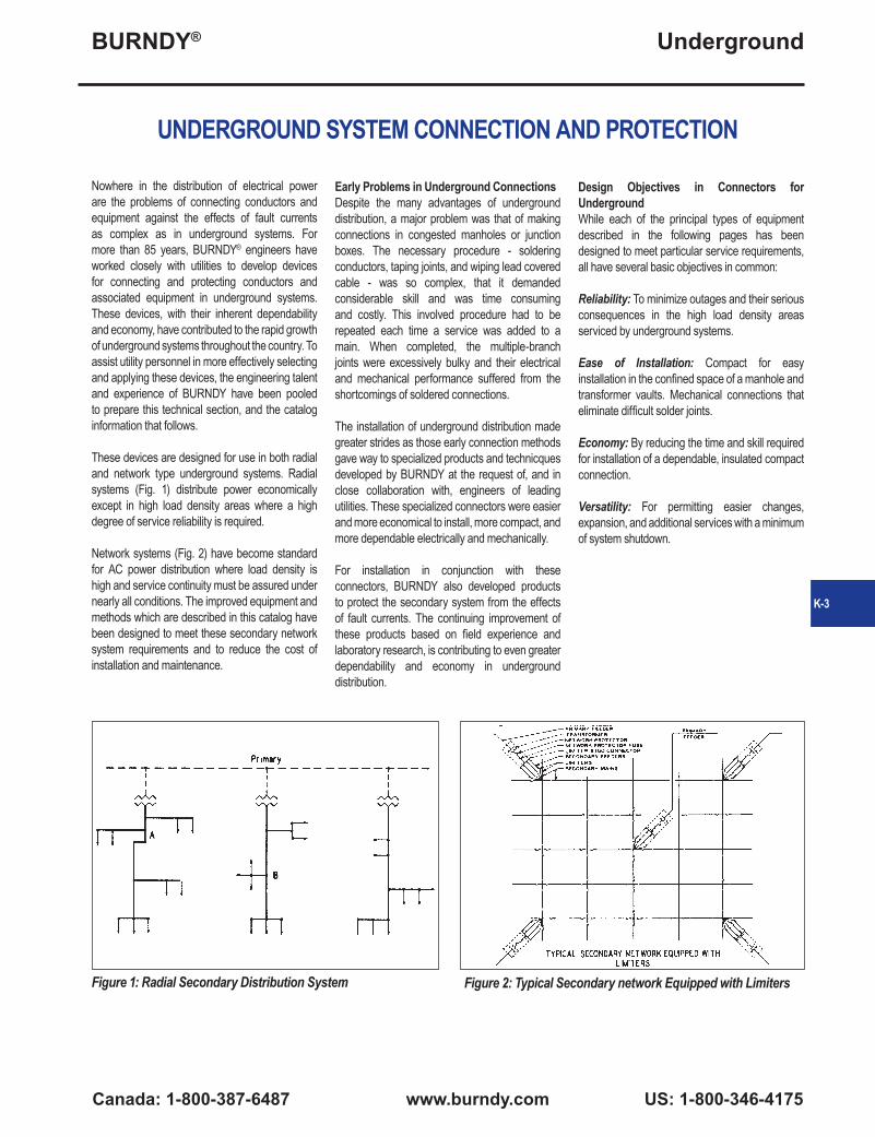
UNDERGROUND SYSTEM CONNECTION AND PROTECTION
Nowhere in the distribution of electrical power are the problems of connecting conductors and equipment against the effects of fault currents as complex as in underground systems. For more than 85 years, BURNDY® engineers have worked closely with utilities to develop devices for connecting and protecting conductors and associated equipment in underground systems. These devices, with their inherent dependability and economy, have contributed to the rapid growth of underground systems throughout the country. To assist utility personnel in more effectively selecting and applying these devices, the engineering talent and experience of BURNDY have been pooled to prepare this technical section, and the catalog information that follows.
These devices are designed for use in both radial and network type underground systems. Radial systems (Fig. 1) distribute power economically except in high load density areas where a high degree of service reliability is required.
Network systems (Fig. 2) have become standard for AC power distribution where load density is high and service continuity must be assured under nearly all conditions. The improved equipment and methods which are described in this catalog have been designed to meet these secondary network system requirements and to reduce the cost of installation and maintenance.
Early Problems in Underground ConnectionsDespite the many advantages of underground distribution, a major problem was that of making connections in congested manholes or junction boxes. The necessary procedure - soldering conductors, taping joints, and wiping lead covered cable - was so complex, that it demanded considerable skill and was time consuming and costly. This involved procedure had to be repeated each time a service was added to a main. When completed, the multiple-branch joints were excessively bulky and their electrical and mechanical performance suffered from the shortcomings of soldered connections.
The installation of underground distribution made greater strides as those early connection methods gave way to specialized products and technicques developed by BURNDY at the request of, and in close collaboration with, engineers of leading utilities. These specialized connectors were easier and more economical to install, more compact, and more dependable electrically and mechanically.
For installation in conjunction with these connectors, BURNDY also developed products to protect the secondary system from the effects of fault currents. The continuing improvement of these products based on field experience and laboratory research, is contributing to even greater dependability and economy in underground distribution.
Design Objectives in Connectors for UndergroundWhile each of the principal types of equipment described in the following pages has been designed to meet particular service requirements, all have several basic objectives in common:
Reliability: To minimize outages and their serious consequences in the high load density areas serviced by underground systems.
Ease of Installation: Compact for easy installation in the confined space of a manhole and transformer vaults. Mechanical connections that eliminate difficult solder joints.
Economy: By reducing the time and skill required for installation of a dependable, insulated compact connection.
Versatility: For permitting easier changes, expansion, and additional services with a minimum of system shutdown.
Figure 1: Radial Secondary Distribution System Figure 2: Typical Secondary network Equipped with Limiters
K-3

BURNDY®
US: 1-800-346-4175 www.burndy.com Canada: 1-800-387-6487
Underground
TYPES OF BURNDY® UNDERGROUND CONNECTORS & ACCESSORIES
The MOLE™ and HYCRAB™The most popular of the engineered connectors developed specifically for underground manholes and trasformer vaults are the MOLE™ and HYCRAB™ that provide for multiple connections at a single junction point of main, feeder, and service cables. Pre-insulated to eliminate extensive taping, these connectors are essentially bus bars with several cable outlets: mechanical installation of the MOLE™, and compression installation in the HYCRAB™.
Limiters and FusesTo prevent “roasting” of cable insulation, resulting from fault current, BURNDY has developed cable limiters that are inserted in each secondary cable at all junction points. Network protector fuses have been designed to back up the protector breaker in teh event of a malfunction during a transformer or primary cable fault. By coordinating the time current characteristics of the fuse with those of the cable limiters, the possibility of limiter blowing on primary faults is eliminated, which in turn redcuces the fault finding task. Also, limiter, fuse, and cable insulation characteristics must be carefully coordinated to assure isolating a fault on the secondary before it can cause extensive damage or interrupt service in other sections of the secondary system.
High Capacity Limiter 200,000 Amperes at 600 VoltsThe BURNDY® High Capacity Limiter is designed to economically protect electrical distribution systems from the destructive effect of high energy faults. The increasing number of 600 volt secondary network installations for industrial and commercial applications demand a cable limiter that can safely interrupt 200,000 amperes (symmetrical available) and one that will also completely coordinate with the higher voltage network protector fuses.
Available fault currents as high as 200,000 amperes rms at 600 volts across the fusible elements have been interrupted during tests on the
BURNDY® High Capacity Limiter. The power factor during these tests was less than 15%, thereby imposing the most difficult clearing conditions. No external disturbance is experienced upon clearing fault currents from the “float” value to 200,000 amperes. The quartz filler absorbs the intense energy generated by interrupting the fault current. The quartz fuses into tobular fulgurites, with a high dielectric strength, and forms an insulating barrier between the melted link sections. This action prevents restrike of the internal arc. The rugged glass melamine housing provides a vessel that completely contains the developed energy.
This carefully developed time-current characteristcs and rigid manufacturing tolerances assure proper coordination with the network protector fuses and the insulation damage characteristics of 4/0, 250, 350, 500, and 750 kcmil cable.
The High Capacity Limiter is available in four variations to accommodate a variety of installation practices. The Type HYS has cable sockets at both ends, which allow for indenting to the cable ends with a hydraulic BURNDY® HYPRESS™. The HYAO type has an offset lug on one end which permits back-to-back mounting on bus bar.
For those installations where the BURNDY® MOLE™ product is used for manhole junctions or transformer vault buses, the Type HYM permits a replaceable connection of the limiter directly to the MOLE outlet at one end and a compression cable connection at the other.
Modern electrical distribution systems require low
cost protection to safeguard costly equipment and quickly isolate faults, so that the undamaged portions of the system may function normally. BURNDY® High Capacity Limiters assure positive, economical protection when installed in properly designed systems.
Compression ConnectorsBURNDY® HYDENT™ compression type connectors, and installation tools, have been designed for splicing and terminating copper as well as aluminum underground cables, in both primary and secondary circuits. BURNDY tools and dies are custom designed to produce sound electrical, and mechanical joints on BURNDY connectors. The use of the BURNDY® Engineered System with matched tools, connectors and dies, assures optimum results.
Residential UndergroundThe trend toward improvement in neighborhood appearances, and the elimination of storm outages, tree trimming, etc. has created the need for residential underground distribution. To meet these needs, BURNDY offers: Mechanical type pre-insulated multi-conductor terminal connectors for submersible transformer locations; and compact multiconductor connectors for above ground transformer and enclosures. For service taps, BURNDY offers: Pre-insulated multi-conductor compression and mechanical connectors; and a range taking compression connector for below grade service. Power pedestals for direct burial, above ground application, and conduit systems are offered. Residential Underground Fuse Block assembly with replaceable fuse for each service cable is also available.
K-4

BURNDY®
Canada: 1-800-387-6487 www.burndy.com US: 1-800-346-4175
Underground
MULTIPLE OUTLET CONNECTORS
Connectors for AluminumFor systems where aluminum is used, connectors especially designed for aluminum conductors are available in bolted and compression types: HYCRAB™, HYPLUG™, HYREDUCER™, and HYSOCKET. Aluminum conductors can be connected to standard MOLE™ connectors by using HYPLUG™ adapters.
Multiple Outlet ConnectorsThe increasing use in modern electrical distribution systems of junction points where several relatively large cables must be connected, has brought about the development of BURNDY® MOLE™ line equipment to speed up and simplify the making of such connections. The modern tendency toward network systems not only in underground utility practice but also in industrial wiring, has greatly increased the number of multi-connection joints.
The BURNDY® MOLE™ and HYCRAB™ connectors are insulated bus bars with multiple connector outlets for service cables, secondary mains or equipment leads. In the MOLE™, clamping action secures conductors to the connector; in the HYCRAB™, connections are made by indenting with a compression tool. Both
lines of insulated connectors offer the following basic advantages:
1. Ease of Economy and Installations: The ease and reduction of time required to make and insulate dependable multi-connections greatly reduces the cost of installation. The compact design makes maximum use of space and provides for simplified racking.
2. Versatility for System Modification: The MOLE™ and HYCRAB™ are designed to accommodate the secondary main and service cables, and permit easy modification or later additions. The numerous available connector configurations permit a wide variety of arrangements of cables and equipment connections. The 600 volt rating of the MOLE™ and HYCRAB™ insulation provides for efficient operation at all standard utilization voltages.
3. Efficient, Dependable Performance: The MOLE™ and HYCRAB™ connectors assure permanent, high conductivity connections, good moisture seal, and insulation that resists the severest condition encountered in underground installations.
MOLE™ and HYCRAB™ InsulationThe location in vaults and manholes often exposes these connectors to immersion in water, chemical, and other contaminants, as well as to heat from overload or fault currents. The MOLE™ and HYCRAB™ insulations provide electrical, mechanical, and thermal properties essential to assure the service continuity of underground distribution systems.
Recognizing the importance of proper connection insulation, BURNDY established performance specifications exceeding those of 600 volt cable insulation.
K-5

BURNDY®
US: 1-800-346-4175 www.burndy.com Canada: 1-800-387-6487
Underground
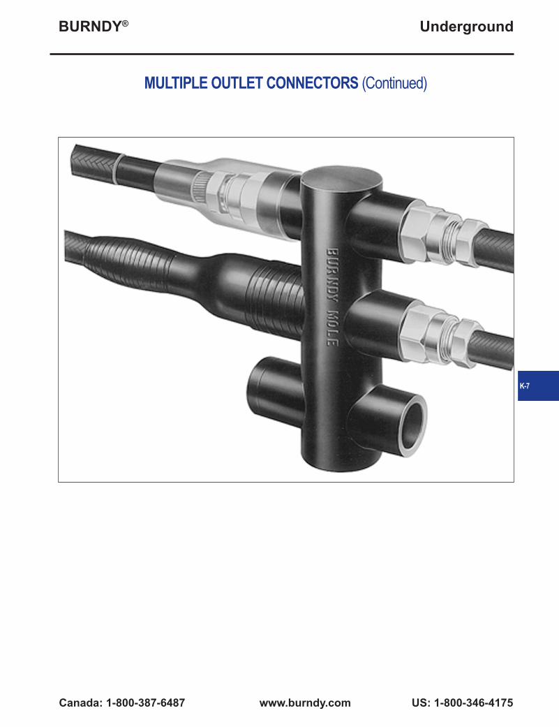
MULTIPLE OUTLET CONNECTORS (Continued)
The MOLE™ and MOLE™ AccessoriesThe BURNDY® MOLE™ is a multi-cable connectors that consists of a pre-insulated copper bus bar with threaded outlets that permit a minimum of two cables to be connected by means of a socket, nut, and cone assembly (Illustration A). The clamping action of the socket, nut, and cone assembly on the cable develops high contact pressures that maintain joint conductivities greater than 100% of the continuous conductor.
The MOLE™ design affords exceptional versatility in four ways:
1. MOLE™ outlets can be plugged-off until needed for the addition of cables.
2. Installed cables can be easily removed.3. Cable sizes can be increased by changing
the socket, nut, and cone assembly.4. The number of outlets may be increased by
joining MOLE™ connectors with a MOLE™ coupler.
InsulationThe copper bus bar insert is encased in a molded insulating jacket that eliminates crotch taping. The thickness of the jacket prevents any possibility of the insert weight to cause the insulation at the supports to flow away at the high temperatures of fault conditions.
RatingsMOLE™ connectors are rated at 1500, 2000, 2500, and 3000 amperes, based on teh maximum current the insert cross-section can carry. Each outlet can carry the full rated current of the cable connected to it.
To avoid exceeding the insert rating, the cables should be arranged in such a manner that most current flows directly across the insert. (See Illustration B.)
InstallationCables are connected to the MOLE™ by means of a socket, nut and compression cone assembly. The socket is threaded into the MOLE™ insert. The stripped cable end is inserted into nut and compression cone, and then into the socket where it is securely clamped by tightening the nut. The joint is then sealed watertight in one of three ways:• Taping;• MOLE™ Outlet Insulating Sleeves, sealed
with a minimum of taping;• NOTAPE™ MOLE™ Sleeve, sealed to the
cable and MOLE™ insulation by two non-corrosive hose clamps.
Tests under flooding and other adverse conditions demonstrate that such joints are impervious to water.
AccessoriesA socket, cone and nut assembly is screwed into each MOLE™ outlet to which a cable is to be connected. The socket has a tapered recess into which the clamping nut forces the cable into the compression cone. The cone is slotted to controlled widths and depths for maximum flexibility, and its inside surface is serrated for low contact resistance and high pullout strength.
Plug seal MOLE™ outlets not in use. The MOLE™ is delivered with one-fourth of its outlets sealed with plugs. Additional plugs may be ordered.
MOLE™ couplers facilitate system expansion by joining additional MOLE™ connectors to those already installed. Couplers are easily installed in end or side outlets of the MOLE™, and make connections that are effective both electrically and mechanically.
Illustration A
Illustration B
K-6
BURNDY®
Canada: 1-800-387-6487 www.burndy.com US: 1-800-346-4175
Underground
MULTIPLE OUTLET CONNECTORS (Continued)
K-7

BURNDY®
US: 1-800-346-4175 www.burndy.com Canada: 1-800-387-6487
Underground
HOW TO ORDER YOUR BURNDY® MOLE™This MOLE™ connector section is arranged so that all the information necessary for ordering
standard MOLE™ connections is contained on a single page.
MOLE™ Connector listings are arranged by:
Amperes: 1500; 2000-2500; 3000
MOLE™ Type: ZM, ZMT, ZME, etc. within each ampere grouping
Cable Outlet Ranges:Symbol “A” = #6 Str. - 600 kcmil; 5/8”Symbol “B” = #2 Str. - 1000 kcmil; 7/8”Symbol “C” = 500 - 1500 kcmil; 1-1/8”
Cable Outlet Arrangement:Depending on ampere group, outlets may be all “A” or “B” cable size, or may be combinations of sizes; Outlet #1, “A”: all other outlets “B”, etc. (See suffix list below.)
Number of Outlets per MOLE™:From 2 to 16 outlets depending on MOLE™ type (any number can be supplied).
Catalog Numbers, Dimensions, and Weights.
MOLE™ CONNECTORS ARE ORDERED BY THE FOLLOWING PROCEDURE:
1. Determine amperage that meets requirements and located it in the MOLE™ ampere page listings.
2. Choose MOLE™ configuration desired by Type (ZM, ZME, ZMT, etc.) within ampere group.
3. Decide of the number of outlets that meets your requirements.
4. Decide on the cable ranges required for each outlet.
5. Select cable outlet arrangement for MOLE™ listing: outlet #1, “A”: all other “B”, etc.
EXAMPLE:Installation load capacity: 2000 amperesConfiguration: outlets on two sides and one endCable ranges: end outlet to accommodate a 1000 kcmil cable; other outlets: two 700 kcmil, two 600 kcmil and two 500 kcmil cables
PROCEDURE:1. Locate 2000 through 2500 ampere MOLE™
groups2. MOLE™ Type ZMT has outlets on two sides
and one end3. Cable outlet symbol “B” = #2 Str. - 1000
kcmil. MOLE™ outlet arrangement: Outlet #1 = “B”, all other outlets = “B”.
4. Catalog Number ZMT7-25B is the correct number. See other pages for socket and nut assembly, compression cones and insulating sleeves.
Suffix List:A3: Outlet #1 = B; all others = AA4: Outlet #1 and X = B; all others = AA7: Outlet #1 and X = C; all others = AA9: Outlet #1 = C; all others = AB12: Outlet #1 = A; all others = BB72: Outlet #1 and X = C; all others = BB92: Outlet #1 = C; all others = B
K-8

BURNDY®
Canada: 1-800-387-6487 www.burndy.com US: 1-800-346-4175
Underground
MOLE™ TYPE ZM
1500 AMPERES
MOLE™ Type ZM — A compact pre-insulated junction for secondary network cables, with multiple outlets for each cable clamping elements.
Outlet Plugs — MOLE™ outlet plugs that facilitate sealing outlets not being used are available, Types Z-P and K-P, sold separately.
Insulating Sleeves — Taping operations for watertight joints are greatly simplified by the use of BURNDY® NOTAPE™ Sleeves Type CM or MOLE™ Insulating Sleeves Type Z-C, sold separately.
Clamping Elements — Outlet Symbols A or B, refer to socket and nut Type Z-NR, and cone Type Z cable clamping elements accommodated. These must be ordered separately.
Catalog Number
Cable Outlet Arrangement
No. of Outlets
LengthInches L
Approx. ShipWt. Lbs.
ZM4-15
All Outlets
A
4 7-1/8 2.60
ZM6-15 6 10-1/8 4.40
ZM8-15 8 13-1/8 6.20
ZM10-15 10 16-1/8 7.80
ZM12-15 12 19-1/8 9.50
ZM14-15 14 22-1/8 11.00
ZM16-15 16 25-1/8 13.00
For outlet combinations not listed call customer service.
OUTLET RANGE: “A” 6 Str. - 600 kcmil
MOLE™DIMENSIONS
K-9

BURNDY®
US: 1-800-346-4175 www.burndy.com Canada: 1-800-387-6487
Underground
MOLE™ TYPE ZMT
1500 AMPERES
MOLE™ Type ZMT— A compact pre-insulated junction for secondary network cables, with multiple outlets for cable clamping elements. Future expansion is provided for by an end outlet which can be joined to an additional MOLE™ by Type ZMS couplers.
Outlet Plugs — Mole outlet plugs that facilitate sealing outlets not being used are available separately, Types Z-P and K-P.
Insulating Sleeves — Taping operations for watertight joints are greatly simplified by the use of BURNDY® NOTAPE™ Sleeves Type CM or MOLE™ Insulating Sleeves Type Z-C are available separately.
Clamping Elements — Outlet Symbols A or B, refer to socket and nut Type Z-NR, and cone Type Z cable clamping elements accommodated. These must be ordered separately.
Catalog Number
Cable Outlet Arrangement
No. of Outlets
LengthInches L
Approx. ShipWt. Lbs.
ZMT3-15
All Outlets
A
3 5 1.30ZMT5-15 5 8 3.00ZMT7-15 7 11 4.50ZMT9-15 9 14 6.20ZMT11-15 11 17 7.90ZMT13-15 13 20 9.70ZMT15-15 15 23 12.00ZMT17-15 17 26 13.00ZMT3-15A3
Outlet #1B
All Other Outlets
A
3 5 1.30ZMT5-15A3 5 8 3.00ZMT7-15A3 7 11 4.50ZMT9-15A3 9 14 6.20ZMT11-15A3 11 17 7.90ZMT13-15A3 13 20 9.70ZMT15-15A3 15 23 12.00ZMT17-15A3 17 26 13.00
OUTLET RANGE: “A” 6 Str. - 600 kcmil “B” 2 Str. - 1000 kcmil
For outlet combinations not listed call customer service.
MOLE™DIMENSIONS
K-10

BURNDY®
Canada: 1-800-387-6487 www.burndy.com US: 1-800-346-4175
Underground
MOLE™ TYPE ZME
1500 AMPERES
MOLE™ Type ZME — A compact pre-insulated junction for secondary network cables, with multiple outlets for cable clamping elements.
Outlet Plugs — Mole outlet plugs that facilitate sealing outlets not being used are Types Z-P and K-P, sold separately.
Insulating Sleeves — Taping operations for watertight joints are greatly simplified by the use of BURNDY® NOTAPE™ Sleeves Type CM or MOLE™ Insulating Sleeves Type Z-C are sold separately.
Clamping Elements— Outlet Symbols A or B, refer to socket and nut Type Z-NR, and cone Type Z cable clamping elements accommodated. These must be ordered separately.
Catalog Number
Cable Outlet Arrangement
No. of Outlets
Length Inches L
Approx. ShipWt. Lbs.
ZME2-15
All Outlets
A
2 7-1/8 2.50ZME3-15 3 10-1/8 4.40ZME4-15 4 13-1/8 6.10ZME5-15 5 16-1/8 7.70ZME6-15 6 19-1/8 9.40ZME7-15 7 22-1/8 11.00ZME8-15 8 25-1/8 13.00
For outlet combinations not listed call customer service.
OUTLET RANGE: “A” 6 Str. - 600 kcmil
MOLE™DIMENSIONS
K-11
BURNDY®
US: 1-800-346-4175 www.burndy.com Canada: 1-800-387-6487
Underground
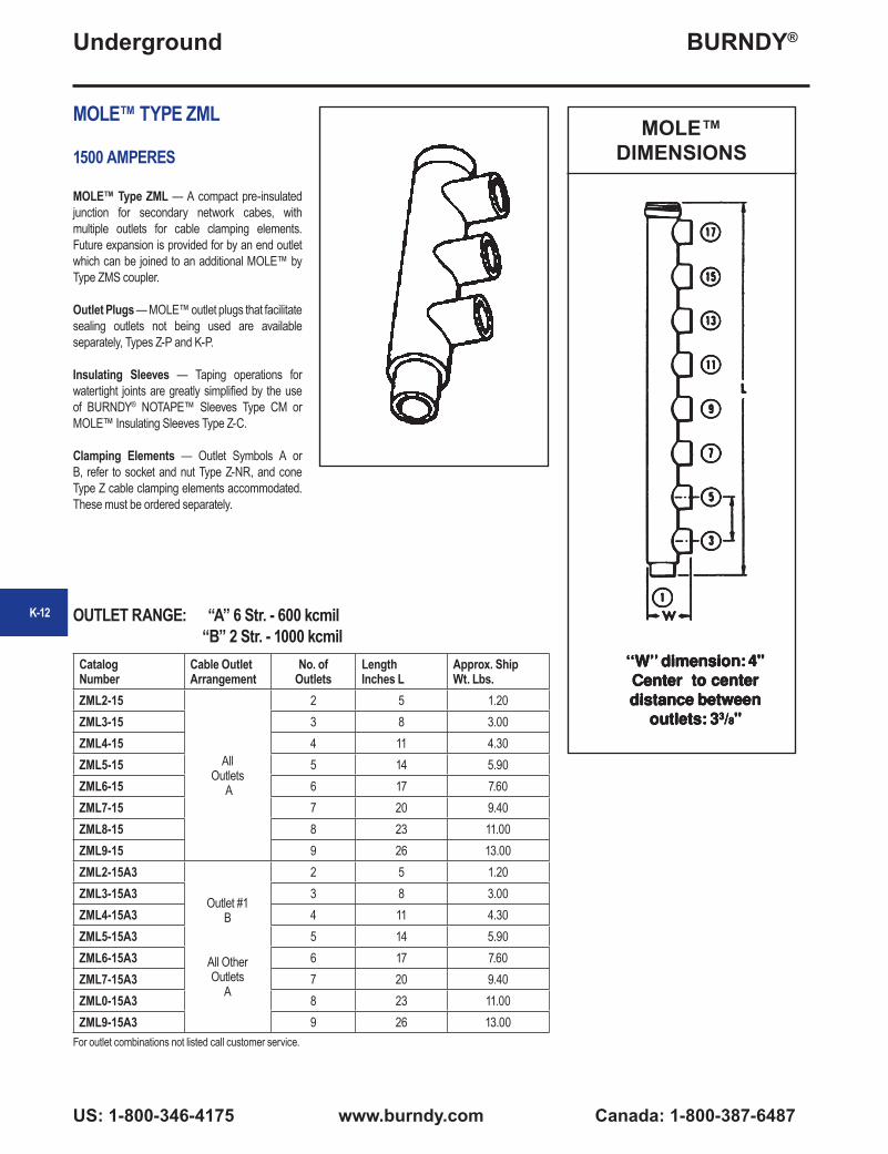
MOLE™ TYPE ZML
1500 AMPERES
MOLE™ Type ZML — A compact pre-insulated junction for secondary network cabes, with multiple outlets for cable clamping elements. Future expansion is provided for by an end outlet which can be joined to an additional MOLE™ by Type ZMS coupler.
Outlet Plugs — MOLE™ outlet plugs that facilitate sealing outlets not being used are available separately, Types Z-P and K-P.
Insulating Sleeves — Taping operations for watertight joints are greatly simplified by the use of BURNDY® NOTAPE™ Sleeves Type CM or MOLE™ Insulating Sleeves Type Z-C.
Clamping Elements — Outlet Symbols A or B, refer to socket and nut Type Z-NR, and cone Type Z cable clamping elements accommodated. These must be ordered separately.
MOLE™DIMENSIONS
Catalog Number
Cable Outlet Arrangement
No. of Outlets
Length Inches L
Approx. ShipWt. Lbs.
ZML2-15
All Outlets
A
2 5 1.20ZML3-15 3 8 3.00ZML4-15 4 11 4.30ZML5-15 5 14 5.90ZML6-15 6 17 7.60ZML7-15 7 20 9.40ZML8-15 8 23 11.00ZML9-15 9 26 13.00ZML2-15A3
Outlet #1B
All Other Outlets
A
2 5 1.20ZML3-15A3 3 8 3.00ZML4-15A3 4 11 4.30ZML5-15A3 5 14 5.90ZML6-15A3 6 17 7.60ZML7-15A3 7 20 9.40ZML0-15A3 8 23 11.00ZML9-15A3 9 26 13.00
For outlet combinations not listed call customer service.
OUTLET RANGE: “A” 6 Str. - 600 kcmil “B” 2 Str. - 1000 kcmil
K-12
BURNDY®
Canada: 1-800-387-6487 www.burndy.com US: 1-800-346-4175
Underground
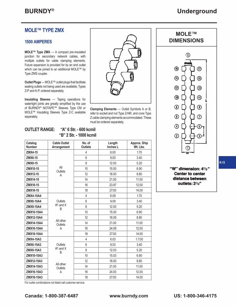
MOLE™ TYPE ZMX
1500 AMPERES
MOLE™ Type ZMX — A compact pre-insulated junction for secondary network cables, with multiple outlets for cable clamping elements. Future expansion is provided for by an end outlet which can be joined to an additional MOLE™ by Type ZMS coupler.
Outlet Plugs — MOLE™ outlet plugs that facilitate sealing outlets not being used are available, Types Z-P and K-P, ordered separately.
Insulating Sleeves — Taping operations for watertight joints are greatly simplified by the use of BURNDY® NOTAPE™ Sleeves Type CM or MOLE™ Insulating Sleeves Type Z-C available separately.
MOLE™DIMENSIONS
Catalog Number
Cable Outlet Arrangement
No. of Outlets
Length Inches L
Approx. ShipWt. Lbs.
ZMX4-15
All Outlets
A
4 6.00 1.70ZMX6-15 6 9.00 3.40ZMX8-15 8 12.00 5.20ZMX10-15 10 15.00 6.90ZMX12-15 12 18.00 8.80ZMX14-15 14 21.00 11.00ZMX16-15 16 23.97 12.00ZMX18-15 18 27.00 14.00ZMX4-15A4
Outlets #1 and X
B
All other Outlets
A
4 6.09 1.70ZMX6-15A4 6 9.09 3.40ZMX8-15A4 8 12.00 5.20ZMX10-15A4 10 15.00 6.90ZMX12-15A4 12 18.09 8.80ZMX14-15A4 14 21.00 11.00ZMX16-15A4 16 24.09 12.00ZMX18-15A4 18 27.00 14.00ZMX4-15A3
Outlets #1 and X
B
All other Outlets
A
4 6.03 1.7.00ZMX6-15A3 6 9.03 3.40ZMX8-15A3 8 12.03 5.20ZMX10-15A3 10 15.03 6.90ZMX12-15A3 12 18.00 8.80ZMX14-15A3 14 21.00 11.00ZMX16-15A3 16 24.00 12.00ZMX18-15A3 18 27.00 14.00
OUTLET RANGE: “A” 6 Str. - 600 kcmil “B” 2 Str. - 1000 kcmil
For outlet combinations not listed call customer service.
Clamping Elements — Outlet Symbols A or B, refer to socket and nut Type Z-NR, and cone Type Z cable clamping elements accommodated. These must be ordered separately.
K-13
BURNDY®
US: 1-800-346-4175 www.burndy.com Canada: 1-800-387-6487
Underground
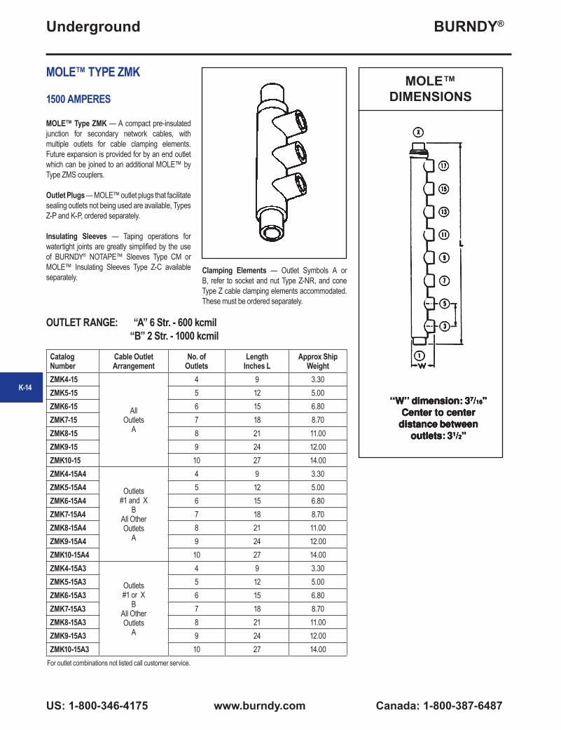
MOLE™ TYPE ZMK
1500 AMPERES
MOLE™ Type ZMK — A compact pre-insulated junction for secondary network cables, with multiple outlets for cable clamping elements. Future expansion is provided for by an end outlet which can be joined to an additional MOLE™ by Type ZMS couplers.
Outlet Plugs — MOLE™ outlet plugs that facilitate sealing outlets not being used are available, Types Z-P and K-P, ordered separately.
Insulating Sleeves — Taping operations for watertight joints are greatly simplified by the use of BURNDY® NOTAPE™ Sleeves Type CM or MOLE™ Insulating Sleeves Type Z-C available separately.
Catalog Number
Cable OutletArrangement
No. of Outlets
Length Inches L
Approx Ship Weight
ZMK4-15
All Outlets
A
4 9 3.30ZMK5-15 5 12 5.00ZMK6-15 6 15 6.80ZMK7-15 7 18 8.70ZMK8-15 8 21 11.00ZMK9-15 9 24 12.00ZMK10-15 10 27 14.00ZMK4-15A4
Outlets #1 and X
BAll Other Outlets
A
4 9 3.30ZMK5-15A4 5 12 5.00ZMK6-15A4 6 15 6.80ZMK7-15A4 7 18 8.70ZMK8-15A4 8 21 11.00ZMK9-15A4 9 24 12.00ZMK10-15A4 10 27 14.00ZMK4-15A3
Outlets #1 or X
BAll Other Outlets
A
4 9 3.30ZMK5-15A3 5 12 5.00ZMK6-15A3 6 15 6.80ZMK7-15A3 7 18 8.70ZMK8-15A3 8 21 11.00ZMK9-15A3 9 24 12.00ZMK10-15A3 10 27 14.00
For outlet combinations not listed call customer service.
OUTLET RANGE: “A” 6 Str. - 600 kcmil “B” 2 Str. - 1000 kcmil
Clamping Elements — Outlet Symbols A or B, refer to socket and nut Type Z-NR, and cone Type Z cable clamping elements accommodated. These must be ordered separately.
MOLE™DIMENSIONS
K-14

BURNDY®
Canada: 1-800-387-6487 www.burndy.com US: 1-800-346-4175
Underground
MOLE™ TYPE ZM
2000-2500 AMPERES
MOLE™ Type ZM — A compact pre-insulated junction for secondary network cables, with multiple outlets for cable clamping elements.
Outlet Plugs — MOLE™ outlet plugs that facilitate sealing outlets not being used are available, Types Z-P and K-P, ordered separately.
Insulating Sleeves — Taping operations for watertight joints are greatly simplified by the use of BURNDY® NOTAPE™ Sleeves Type CM or MOLE™ Insulating Sleeves Type Z-C available separately.
Clamping Elements — Outlet Symbols A or B, refer to socket and nut Type Z-NR, and cone Type Z cable clamping elements accommodated. These must be ordered separately.
Catalog Number
Cable Outlet Arrangement
No. of Outlets
Length Inches L
Approx. ShipWt. Lbs.
ZM4-25
All Outlets
A
4 8 4.40ZM6-25 6 11-1/2 7.00ZM8-25 8 15 9.70ZM10-25 10 18-1/2 13.00ZM12-25 12 22 14.00ZM14-25 14 25-1/2 15.00ZM16-25 16 29 18.00ZM4-25B
All Outlets
B
4 8 4.40ZM6-25B 6 11-1/2 7.00ZM8-25B 8 15 9.70ZM10-25B 10 18-1/2 13.00ZM12-25B 12 22 14.00ZM14-25B 14 25-1/2 15.00ZM16-25B 16 29 18.00
OUTLET RANGE: “A” 6 Str. - 600 kcmil “B” 2 Str. - 1000 kcmil
For outlet combinations not listed call customer service.
MOLE™DIMENSIONS
K-15
BURNDY®
US: 1-800-346-4175 www.burndy.com Canada: 1-800-387-6487
Underground
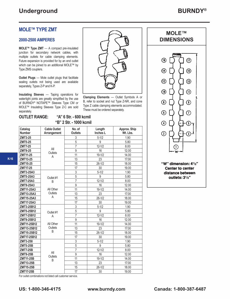
MOLE™ TYPE ZMT
2000-2500 AMPERESMOLE™ Type ZMT — A compact pre-insulated junction for secondary network cables, with multiple outlets for cable clamping elements. Future expansion is provided for by an end outlet which can be joined to an additional MOLE™ by Type ZMS couplers.
Outlet Plugs — Mole outlet plugs that facilitate sealing outlets not being used are available separately, Types Z-P and K-P.
Insulating Sleeves — Taping operations for watertight joints are greatly simplified by the use of BURNDY® NOTAPE™ Sleeves Type CM or MOLE™ Insulating Sleeves Type Z-C are sold separately.
Catalog Number
Cable Outlet Arrangement
No. of Outlets
Length Inches L
Approx. ShipWt. Lbs.
ZMT3-25
All Outlets
A
3 5-1/2 1.90ZMT5-25 5 9 5.80ZMT7-25 7 12-1/2 8.00ZMT9-25 9 16 12.00ZMT11-25 11 19-1/2 14.00ZMT13-25 13 23 17.00ZMT15-25 15 26-1/2 18.00ZMT17-25 17 30 19.00ZMT3-25A3
Outlet #1B
All Other Outlets
A
3 5-1/2 1.90ZMT5-25A3 5 9 5.80ZMT7-25A3 7 12-1/2 8.00ZMT9-25A3 9 16 12.00ZMT11-25A3 11 19-1/2 14.00ZMT13-25A3 13 23 17.00ZMT15-25A3 15 26-1/2 18.00ZMT17-25A3 17 30 19.00ZMT3-25B12
Outlet #1A
All Other Outlets
B
3 5-1/2 1.90ZMT5-25B12 5 9 5.80ZMT7-25B12 7 12-1/2 8.00ZMT9-25B12 9 16 12.00ZMT11-25B12 11 19-1/2 14.00ZMT13-25B12 13 23 17.00ZMT15-25B12 15 26-1/2 18.00ZMT17-25B12 17 30 19.00ZMT3-258
All Outlets
B
3 5-1/2 1.90ZMT5-25B 5 9 5.80ZMT7-25B 7 12-1/2 8.00ZMT9-25B 9 16 12.00ZMT11-25B 11 19-1/2 14.00ZMT13-25B 13 23 17.00ZMT15-25B 15 26-1/2 18.00ZMT17-25B 17 30 19.00
Clamping Elements — Outlet Symbols A or B, refer to socket and nut Type Z-NR, and cone Type Z cable clamping elements accommodated. These must be ordered separately.
OUTLET RANGE: “A” 6 Str. - 600 kcmil “B” 2 Str. - 1000 kcmil
For outlet combinations not listed call customer service.
MOLE™DIMENSIONS
K-16
BURNDY®
Canada: 1-800-387-6487 www.burndy.com US: 1-800-346-4175
Underground
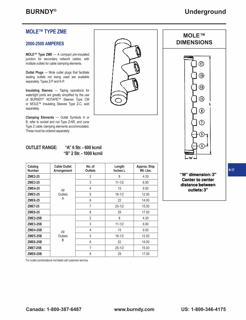
MOLE™ TYPE ZME
2000-2500 AMPERES
MOLE™ Type ZME — A compact pre-insulated junction for secondary network cables, with multiple outlets for cable clamping elements.
Outlet Plugs — Mole outlet plugs that facilitate sealing outlets not being used are available separately, Types Z-P and K-P.
Insulating Sleeves — Taping operations for watertight joints are greatly simplified by the use of BURNDY® NOTAPE™ Sleeves Type CM or MOLE™ Insulating Sleeves Type Z-C, sold separately.
Clamping Elements — Outlet Symbols A or B, refer to socket and nut Type Z-NR, and cone Type Z cable clamping elements accommodated. These must be ordered separately.
Catalog Number
Cable Outlet Arrangement
No. of Outlets
Length Inches L
Approx. ShipWt. Lbs.
ZME2-25
All Outlets
A
2 8 4.30ZME3-25 3 11-1/2 6.90ZME4-25 4 15 9.50ZME5-25 5 18-1/2 12.00ZME6-25 6 22 14.00ZME7-25 7 25-1/2 15.00ZME8-25 8 29 17.00ZME2-25B
All Outlets
B
2 8 4.30ZME3-25B 3 11-1/2 6.90ZME4-25B 4 15 9.50ZME5-25B 5 18-1/2 12.00ZME6-25B 6 22 14.00ZME7-25B 7 25-1/2 15.00ZME8-25B 8 29 17.00
OUTLET RANGE: “A” 6 Str. - 600 kcmil “B” 2 Str. - 1000 kcmil
For outlet combinations not listed call customer service.
MOLE™DIMENSIONS
K-17

BURNDY®
US: 1-800-346-4175 www.burndy.com Canada: 1-800-387-6487
Underground
MOLE™ TYPE ZML
2000-2500 AMPERESMOLE™ Type ZML — A compact pre-insulated junction for secondary network cabes, with multiple outlets for cable clamping elements. Future expansion is provided for by an end outlet which can be joined to an additional MOLE™ by Type ZMS coupler.
Outlet Plugs — MOLE™ outlet plugs that facilitate sealing outlets not being used are available seaparately, Types Z-P and K-P.
Insulating Sleeves — Taping operations for watertight joints are greatly simplified by the use of BURNDY® NOTAPE™ Sleeves Type CM or MOLE™ Insulating Sleeves Type Z-C, sold separately.
Catalog Number
Cable Outlet Arrangement
No. of Outlets
Length Inches L
Approx Ship Wt. Lbs.
ZML2-25
All Outlets
A
2 5-1/2 1.80ZML3-25 3 9 5.80ZML4-25 4 12-1/2 7.90ZML5-25 5 16 12.00ZML6-25 6 19-1/2 14.00ZML7-25 7 23 16.00ZML8-25 8 26-1/2 17.00ZML9-25 9 30 19.00ZML2-25A3
Outlet #1B
All Other Outlets
A
2 5-1/2 1.80ZML3-25A3 3 9 5.80ZML4-25A3 4 12-1/2 7.90ZML5-25A3 5 16 12.00ZML6-25A3 6 19-1/2 14.00ZML7-25A3 7 23 16.00ZML8-25A3 8 26-1/2 17.00ZML9-25A3 9 30 19.00ZML2-25B12
Outlet #1A
All Others Outlets
B
2 5-1/2 1.80ZML3-25B12 3 9 5.80ZML4-25B12 4 12-1/2 7.90ZML5-25B12 5 16 12.00ZML6-25B12 6 19-1/2 14.00ZML7-25B12 7 23 16.00ZML8-25B12 8 26-1/2 17.00ZML9-25B12 9 30 19.00ZML2-25B
All Outlets
B
2 5-1/2 1.80ZML3-25B 3 9 5.80ZML4-25B 4 12-1/2 7.90ZML5-25B 5 16 12.00ZML6-25B 6 19-1/2 14.00ZML7-25B 7 23 16.00ZML8-25B 8 26-1/2 17.00ZML9-25B 9 30 19.00
Clamping Elements — Outlet Symbols A or B, refer to socket and nut Type Z-NR, and cone Type Z cable clamping elements accommodated. These must be ordered separately.
OUTLET RANGE: “A” 6 Str. - 600 kcmil “B” 2 Str. - 1000 kcmil
For outlet combinations not listed call customer service.
MOLE™DIMENSIONS
K-18
BURNDY®
Canada: 1-800-387-6487 www.burndy.com US: 1-800-346-4175
Underground
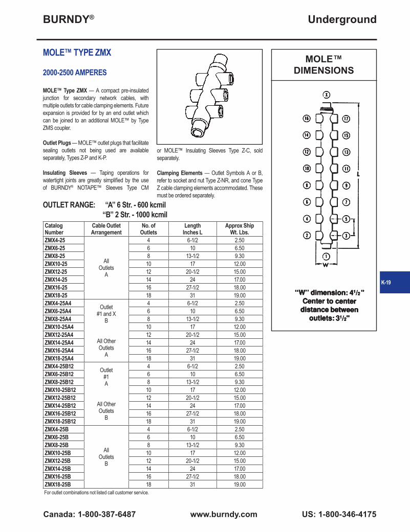
MOLE™ TYPE ZMX
2000-2500 AMPERES
MOLE™ Type ZMX — A compact pre-insulated junction for secondary network cables, with multiple outlets for cable clamping elements. Future expansion is provided for by an end outlet which can be joined to an additional MOLE™ by Type ZMS coupler.
Outlet Plugs — MOLE™ outlet plugs that facilitate sealing outlets not being used are available separately, Types Z-P and K-P.
Insulating Sleeves — Taping operations for watertight joints are greatly simplified by the use of BURNDY® NOTAPE™ Sleeves Type CM
Catalog Number
Cable Outlet Arrangement
No. of Outlets
LengthInches L
Approx Ship Wt. Lbs.
ZMX4-25
All Outlets
A
4 6-1/2 2.50ZMX6-25 6 10 6.50ZMX8-25 8 13-1/2 9.30ZMX10-25 10 17 12.00ZMX12-25 12 20-1/2 15.00ZMX14-25 14 24 17.00ZMX16-25 16 27-1/2 18.00ZMX18-25 18 31 19.00ZMX4-25A4 Outlet
#1 and XB
All Other Outlets
A
4 6-1/2 2.50ZMX6-25A4 6 10 6.50ZMX8-25A4 8 13-1/2 9.30ZMX10-25A4 10 17 12.00ZMX12-25A4 12 20-1/2 15.00ZMX14-25A4 14 24 17.00ZMX16-25A4 16 27-1/2 18.00ZMX18-25A4 18 31 19.00ZMX4-25B12 Outlet
#1A
All Other Outlets
B
4 6-1/2 2.50ZMX6-25B12 6 10 6.50ZMX8-25B12 8 13-1/2 9.30ZMX10-25B12 10 17 12.00ZMX12-25B12 12 20-1/2 15.00ZMX14-25B12 14 24 17.00ZMX16-25B12 16 27-1/2 18.00ZMX18-25B12 18 31 19.00ZMX4-25B
All Outlets
B
4 6-1/2 2.50ZMX6-25B 6 10 6.50ZMX8-25B 8 13-1/2 9.30ZMX10-25B 10 17 12.00ZMX12-25B 12 20-1/2 15.00ZMX14-25B 14 24 17.00ZMX16-25B 16 27-1/2 18.00ZMX18-25B 18 31 19.00
or MOLE™ Insulating Sleeves Type Z-C, sold separately.
Clamping Elements — Outlet Symbols A or B, refer to socket and nut Type Z-NR, and cone Type Z cable clamping elements accommodated. These must be ordered separately.
OUTLET RANGE: “A” 6 Str. - 600 kcmil “B” 2 Str. - 1000 kcmil
For outlet combinations not listed call customer service.
MOLE™DIMENSIONS
K-19
BURNDY®
US: 1-800-346-4175 www.burndy.com Canada: 1-800-387-6487
Underground
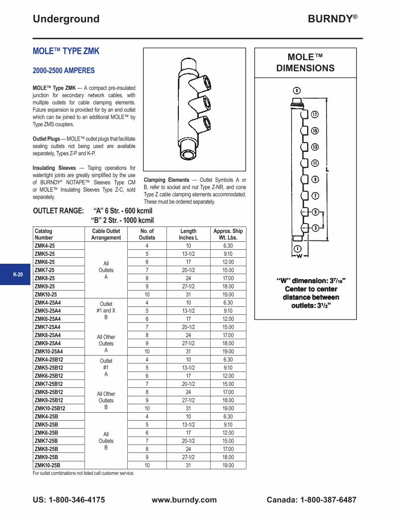
MOLE™ TYPE ZMK
2000-2500 AMPERES
MOLE™ Type ZMK — A compact pre-insulated junction for secondary network cables, with multiple outlets for cable clamping elements. Future expansion is provided for by an end outlet which can be joined to an additional MOLE™ by Type ZMS couplers.
Outlet Plugs — MOLE™ outlet plugs that facilitate sealing outlets not being used are available separately, Types Z-P and K-P.
Insulating Sleeves — Taping operations for watertight joints are greatly simplified by the use of BURNDY® NOTAPE™ Sleeves Type CM or MOLE™ Insulating Sleeves Type Z-C, sold separately.
MOLE™DIMENSIONS
Clamping Elements — Outlet Symbols A or B, refer to socket and nut Type Z-NR, and cone Type Z cable clamping elements accommodated. These must be ordered separately.
Catalog Number
Cable Outlet Arrangement
No. of Outlets
Length Inches L
Approx. ShipWt. Lbs.
ZMK4-25
All Outlets
A
4 10 6.30ZMK5-25 5 13-1/2 9.10ZMK6-25 6 17 12.00ZMK7-25 7 20-1/2 15.00ZMK8-25 8 24 17.00ZMK9-25 9 27-1/2 18.00ZMK10-25 10 31 19.00ZMK4-25A4 Outlet
#1 and XB
All Other Outlets
A
4 10 6.30ZMK5-25A4 5 13-1/2 9.10ZMK6-25A4 6 17 12.00ZMK7-25A4 7 20-1/2 15.00ZMK8-25A4 8 24 17.00ZMK9-25A4 9 27-1/2 18.00ZMK10-25A4 10 31 19.00ZMK4-25B12 Outlet
#1A
All Other Outlets
B
4 10 6.30ZMK5-25B12 5 13-1/2 9.10ZMK6-25B12 6 17 12.00ZMK7-25B12 7 20-1/2 15.00ZMK8-25B12 8 24 17.00ZMK9-25B12 9 27-1/2 18.00ZMK10-25B12 10 31 19.00ZMK4-25B
All Outlets
B
4 10 6.30ZMK5-25B 5 13-1/2 9.10ZMK6-25B 6 17 12.00ZMK7-25B 7 20-1/2 15.00ZMK8-25B 8 24 17.00ZMK9-25B 9 27-1/2 18.00ZMK10-25B 10 31 19.00
OUTLET RANGE: “A” 6 Str. - 600 kcmil “B” 2 Str. - 1000 kcmil
For outlet combinations not listed call customer service.
K-20
BURNDY®
Canada: 1-800-387-6487 www.burndy.com US: 1-800-346-4175
Underground
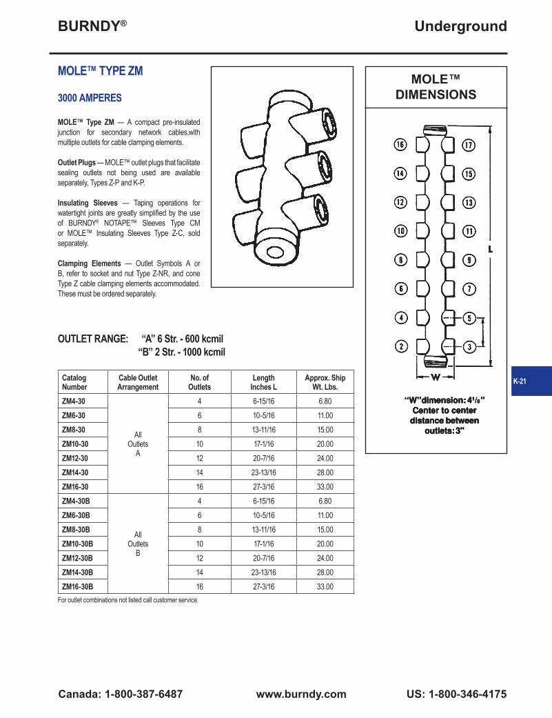
MOLE™ TYPE ZM
3000 AMPERES
MOLE™ Type ZM — A compact pre-insulated junction for secondary network cables,with multiple outlets for cable clamping elements.
Outlet Plugs — MOLE™ outlet plugs that facilitate sealing outlets not being used are available separately, Types Z-P and K-P.
Insulating Sleeves — Taping operations for watertight joints are greatly simplified by the use of BURNDY® NOTAPE™ Sleeves Type CM or MOLE™ Insulating Sleeves Type Z-C, sold separately.
Clamping Elements — Outlet Symbols A or B, refer to socket and nut Type Z-NR, and cone Type Z cable clamping elements accommodated. These must be ordered separately.
Catalog Number
Cable Outlet Arrangement
No. of Outlets
Length Inches L
Approx. ShipWt. Lbs.
ZM4-30
All Outlets
A
4 6-15/16 6.80ZM6-30 6 10-5/16 11.00ZM8-30 8 13-11/16 15.00ZM10-30 10 17-1/16 20.00ZM12-30 12 20-7/16 24.00ZM14-30 14 23-13/16 28.00ZM16-30 16 27-3/16 33.00ZM4-30B
All Outlets
B
4 6-15/16 6.80ZM6-30B 6 10-5/16 11.00ZM8-30B 8 13-11/16 15.00ZM10-30B 10 17-1/16 20.00ZM12-30B 12 20-7/16 24.00ZM14-30B 14 23-13/16 28.00ZM16-30B 16 27-3/16 33.00
MOLE™DIMENSIONS
OUTLET RANGE: “A” 6 Str. - 600 kcmil “B” 2 Str. - 1000 kcmil
For outlet combinations not listed call customer service.
K-21
BURNDY®
US: 1-800-346-4175 www.burndy.com Canada: 1-800-387-6487
Underground
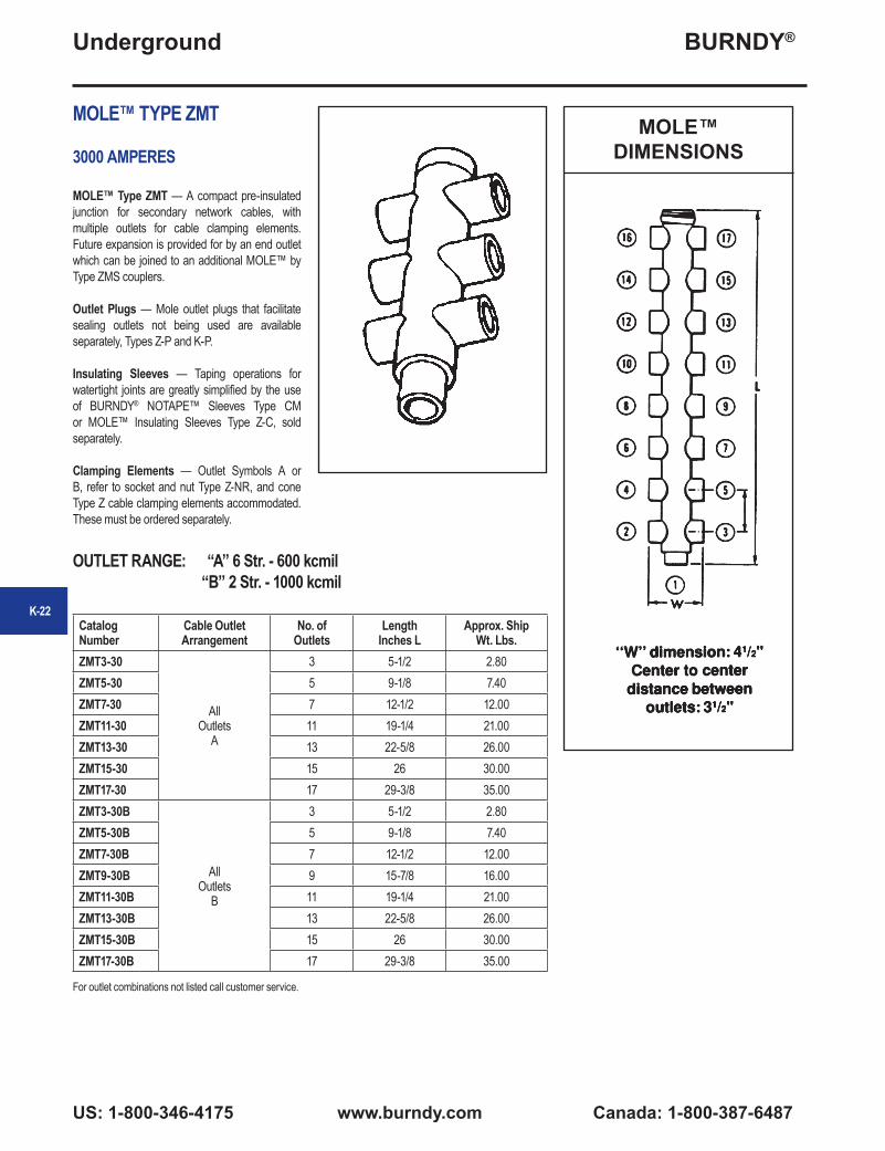
MOLE™ TYPE ZMT
3000 AMPERES
MOLE™ Type ZMT — A compact pre-insulated junction for secondary network cables, with multiple outlets for cable clamping elements. Future expansion is provided for by an end outlet which can be joined to an additional MOLE™ by Type ZMS couplers.
Outlet Plugs — Mole outlet plugs that facilitate sealing outlets not being used are available separately, Types Z-P and K-P.
Insulating Sleeves — Taping operations for watertight joints are greatly simplified by the use of BURNDY® NOTAPE™ Sleeves Type CM or MOLE™ Insulating Sleeves Type Z-C, sold separately.
Clamping Elements — Outlet Symbols A or B, refer to socket and nut Type Z-NR, and cone Type Z cable clamping elements accommodated. These must be ordered separately.
MOLE™DIMENSIONS
Catalog Number
Cable Outlet Arrangement
No. of Outlets
Length Inches L
Approx. ShipWt. Lbs.
ZMT3-30
All Outlets
A
3 5-1/2 2.80ZMT5-30 5 9-1/8 7.40ZMT7-30 7 12-1/2 12.00ZMT11-30 11 19-1/4 21.00ZMT13-30 13 22-5/8 26.00ZMT15-30 15 26 30.00ZMT17-30 17 29-3/8 35.00ZMT3-30B
All Outlets
B
3 5-1/2 2.80ZMT5-30B 5 9-1/8 7.40ZMT7-30B 7 12-1/2 12.00ZMT9-30B 9 15-7/8 16.00ZMT11-30B 11 19-1/4 21.00ZMT13-30B 13 22-5/8 26.00ZMT15-30B 15 26 30.00ZMT17-30B 17 29-3/8 35.00
OUTLET RANGE: “A” 6 Str. - 600 kcmil “B” 2 Str. - 1000 kcmil
For outlet combinations not listed call customer service.
K-22
BURNDY®
Canada: 1-800-387-6487 www.burndy.com US: 1-800-346-4175
Underground
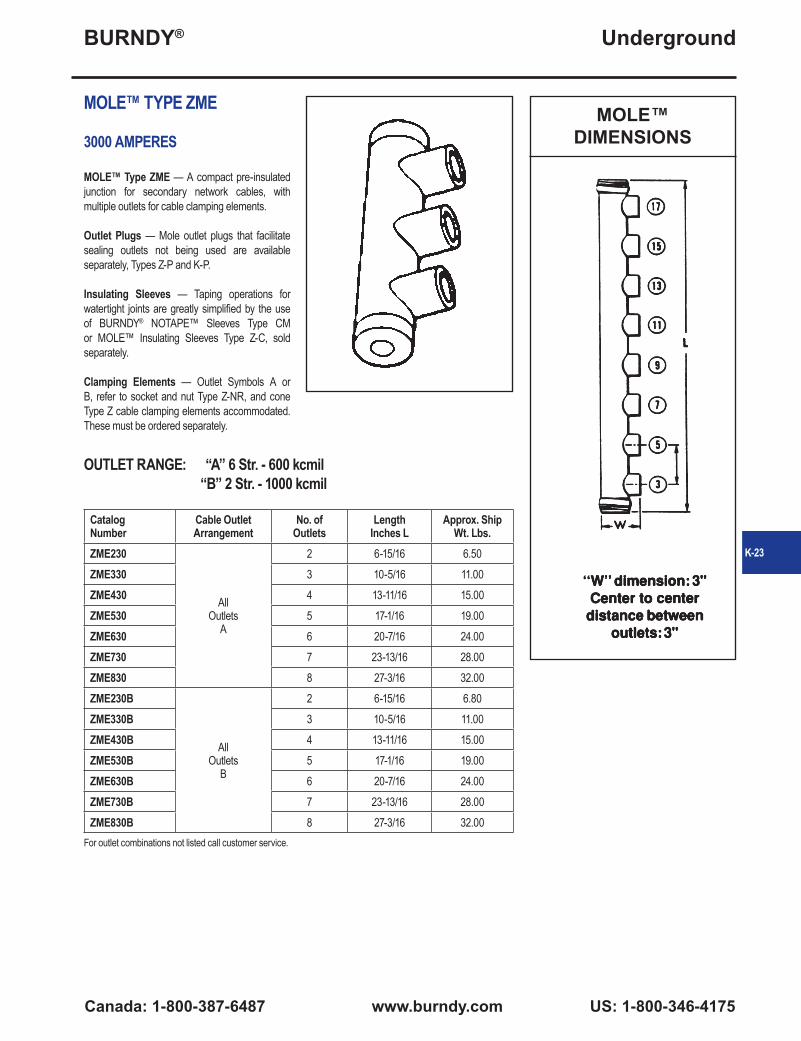
MOLE™ TYPE ZME
3000 AMPERES
MOLE™ Type ZME — A compact pre-insulated junction for secondary network cables, with multiple outlets for cable clamping elements.
Outlet Plugs — Mole outlet plugs that facilitate sealing outlets not being used are available separately, Types Z-P and K-P.
Insulating Sleeves — Taping operations for watertight joints are greatly simplified by the use of BURNDY® NOTAPE™ Sleeves Type CM or MOLE™ Insulating Sleeves Type Z-C, sold separately.
Clamping Elements — Outlet Symbols A or B, refer to socket and nut Type Z-NR, and cone Type Z cable clamping elements accommodated. These must be ordered separately.
Catalog Number
Cable Outlet Arrangement
No. of Outlets
Length Inches L
Approx. ShipWt. Lbs.
ZME230
All Outlets
A
2 6-15/16 6.50ZME330 3 10-5/16 11.00ZME430 4 13-11/16 15.00ZME530 5 17-1/16 19.00ZME630 6 20-7/16 24.00ZME730 7 23-13/16 28.00ZME830 8 27-3/16 32.00ZME230B
All Outlets
B
2 6-15/16 6.80ZME330B 3 10-5/16 11.00ZME430B 4 13-11/16 15.00ZME530B 5 17-1/16 19.00ZME630B 6 20-7/16 24.00ZME730B 7 23-13/16 28.00ZME830B 8 27-3/16 32.00
MOLE™DIMENSIONS
OUTLET RANGE: “A” 6 Str. - 600 kcmil “B” 2 Str. - 1000 kcmil
For outlet combinations not listed call customer service.
K-23
BURNDY®
US: 1-800-346-4175 www.burndy.com Canada: 1-800-387-6487
Underground
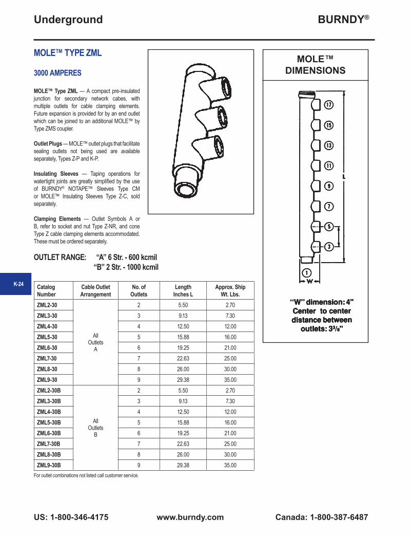
MOLE™ TYPE ZML
3000 AMPERES
MOLE™ Type ZML — A compact pre-insulated junction for secondary network cabes, with multiple outlets for cable clamping elements. Future expansion is provided for by an end outlet which can be joined to an additional MOLE™ by Type ZMS coupler.
Outlet Plugs — MOLE™ outlet plugs that facilitate sealing outlets not being used are available separately, Types Z-P and K-P.
Insulating Sleeves — Taping operations for watertight joints are greatly simplified by the use of BURNDY® NOTAPE™ Sleeves Type CM or MOLE™ Insulating Sleeves Type Z-C, sold separately.
Clamping Elements — Outlet Symbols A or B, refer to socket and nut Type Z-NR, and cone Type Z cable clamping elements accommodated. These must be ordered separately.
MOLE™DIMENSIONS
Catalog Number
Cable Outlet Arrangement
No. of Outlets
Length Inches L
Approx. Ship Wt. Lbs.
ZML2-30
All Outlets
A
2 5.50 2.70ZML3-30 3 9.13 7.30ZML4-30 4 12.50 12.00ZML5-30 5 15.88 16.00ZML6-30 6 19.25 21.00ZML7-30 7 22.63 25.00ZML8-30 8 26.00 30.00ZML9-30 9 29.38 35.00ZML2-30B
All Outlets
B
2 5.50 2.70ZML3-30B 3 9.13 7.30ZML4-30B 4 12.50 12.00ZML5-30B 5 15.88 16.00ZML6-30B 6 19.25 21.00ZML7-30B 7 22.63 25.00ZML8-30B 8 26.00 30.00ZML9-30B 9 29.38 35.00
OUTLET RANGE: “A” 6 Str. - 600 kcmil “B” 2 Str. - 1000 kcmil
For outlet combinations not listed call customer service.
K-24

BURNDY®
Canada: 1-800-387-6487 www.burndy.com US: 1-800-346-4175
Underground
MOLE™ TYPE ZMX
3000 AMPERES
MOLE™ Type ZMX — A compact pre-insulated junction for secondary network cables, with multiple outlets for cable clamping elements. Future expansion is provided for by an end outlet which can be joined to an additional MOLE™ by Type ZMS coupler.
Outlet Plugs — MOLE™ outlet plugs that facilitate sealing outlets not being used are available separately, Types Z-P and K-P.
Insulating Sleeves — Taping operations for watertight joints are greatly simplified by the use of BURNDY® NOTAPE™ Sleeves Type CM or MOLE™ Insulating Sleeves Type Z-C, sold separately.
Clamping Elements — Outlet Symbols A or B, refer to socket and nut Type Z-NR, and cone Type Z cable clamping elements accommodated. These must be ordered separately.
Catalog Number
Cable Outlet Arrangement
No. of Outlets
Length Inches L
Approx. ShipWt. Lbs.
ZMX4-30
All Outlets
A
4 6.50 3.90
ZMX6-30 6 10.13 8.90
ZMX8-30 8 13.50 13.00
ZMX10-30 10 16.88 18.00
ZMX12-30 12 20.25 23.00
ZMX14-30 14 23.64 27.00
ZMX16-30 16 27.02 31.00
ZMX18-30 18 30.40 35.00
ZMX4-30B
All Outlets
B
4 6.50 3.90
ZMX6-30B 6 10.13 8.90
ZMX8-30B 8 13.50 13.00
ZMX10-30B 10 16.88 18.00
ZMX14-30B 14 23.64 27.00
ZMX18-30B 18 30.40 35.00
MOLE™DIMENSIONS
OUTLET RANGE: “A” 6 Str. - 600 kcmil “B” 2 Str. - 1000 kcmil
For outlet combinations not listed call customer service.
K-25

BURNDY®
US: 1-800-346-4175 www.burndy.com Canada: 1-800-387-6487
Underground
MOLE™ TYPE ZMK
3000 AMPERES
MOLE™ Type ZMK — A compact pre-insulated junction for secondary network cables, with multiple outlets for cable clamping elements. Future expansion is provided for by an end outlet which can be joined to an additional MOLE™ by Type ZMS couplers.
Outlet Plugs — MOLE™ outlet plugs that facilitate sealing outlets not being used are available separately, Types Z-P and K-P.
Insulating Sleeves — Taping operations for watertight joints are greatly simplified by the use of BURNDY® NOTAPE™ Sleeves Type CM or MOLE™ Insulating Sleeves Type Z-C, ordered separately.
Clamping Elements — Outlet Symbols A or B, refer to socket and nut Type Z-NR, and cone Type Z cable clamping elements accommodated. These must be ordered separately.
Catalog Number
Cable Outlet Arrangement
No. of Outlets
Length Inches L
Approx. ShipWt. Lbs.
ZMK430
All Outlets
A
4 10-1/8 8.80
ZMK530 5 13-1/2 13.00
ZMK630 6 16-7/8 18.00
ZMK730 7 20-1/4 23.00
ZMK830 8 23-5/8 27.00
ZMK930 9 27 31.00
ZMK1030 10 30-3/8 35.00
ZMK430B
All Outlets
B
4 10-1/4 8.80
ZMK530B 5 13-5/8 13.00
ZMK630B 6 17 18.00
ZMK730B 7 20-3/8 23.00
ZMK830B 8 23-3/4 27.00
ZMK1030B 10 30-1/2 35.00
OUTLET RANGE: “A” 6 Str. - 600 kcmil “B” 2 Str. - 1000 kcmil
For outlet combinations not listed call customer service.
MOLE™DIMENSIONS
4"
3 3/8"
K-26

BURNDY®
Canada: 1-800-387-6487 www.burndy.com US: 1-800-346-4175
Underground
TYPE ZMLDN
MOLE™ STUD CONNECTOR
For Connecting Copper Cables to Network Protector
To terminate one or more cables at the studs of distribution transformers, network protectors or other apparatus. The body, except for the stud clamping element is completely insulated. A separate clamping cap over the stud is provided that permits easy removal of the MOLE™ Stud Connector. This permits work to be done on the Network Protector without unduly disturbing the cables.
Outlet Plugs — MOLE™ outlet plugs that facilitate sealing outlets not being used are available separately, Types Z-P and K-P.
Insulating Sleeves — Taping operations for watertight joints are greatly simplified by the use of BURNDY® NOTAPE™ Sleeves Type CM or MOLE™ Insulating Sleeves Type Z-C, ordered separately.
Clamping Elements — Outlet Symbols A or B, refer to socket and nut Type Z-NR, and cone Type Z cable clamping elements accommodated. These must be ordered separately.
OUTLET RANGE: “A” 6 Str. - 600 kcmil “B” 2 Str. - 1000 kcmil
* Can be furnished with more than 6 outlets.
Catalog Number
Ampere Capacity
Cable Outlet Arrangement
* No. of Outlets
A Dimensions in Inches Approx. Ship
Wt. Lbs.Stud Dia.
Threads per Inch B C J L W
ZMLDN1-15
1500
All Outlets
A
1 1-1/2 12 2-11/16 — 1/2 7-3/8 3 4.70
ZMLDN2-15 2 1-1/2 12 2-11/16 3 1/2 10-3/8 3 6.80
ZMLDN3-15 3 1-1/2 12 2-11/16 3 1/2 13-3/8 3 8.80
ZMLDN4-15 4 1-1/2 12 2-11/16 3 1/2 16-3/8 3 11.00
ZMLDN5-15 5 1-1/2 12 2-11/16 3 1/2 19-3/8 3 13.30
ZMLDN6-15 6 1-1/2 12 2-11/16 3 1/2 22-3/8 3 15.50
ZMLDN1-20
2000
1 1-1/2 12 2-11/16 — 1/2 7-7/8 3-7/16 8.50
ZMLDN2-20 2 1-1/2 12 2-11/16 3-1/2 1/2 11-3/8 3-7/16 12.00
ZMLDN3-20 3 1-1/2 12 2-11/16 3-1/2 1/2 14-7/8 3-7/16 14.00
ZMLDN4-20 4 1-1/2 12 2-11/16 3-1/2 1/2 18-3/8 3-7/16 17.00
ZMLDN5-20 5 1-1/2 12 2-11/16 3-1/2 1/2 21-7/8 3-7/16 20.00
ZMLDN6-20 6 1-1/2 12 2-11/16 3-1/2 1/2 25-3/8 3-7/16 23.00
ZMLDN1-20B
All Outlets
B
1 1-1/2 12 2-11/16 — 1/2 7-7/8 3-7/16 8.50
ZMLDN2-20B 2 1-1/2 12 2-11/16 3-1/2 1/2 11-3/8 3-7/16 12.00
ZMLDN3-20B 3 1-1/2 12 2-11/16 3-1/2 1/2 14-7/8 3-7/16 14.00
ZMLDN4-20B 4 1-1/2 12 2-11/16 3-1/2 1/2 18-3/8 3-7/16 17.00
ZMLDN5-20B 5 1-1/2 12 2-11/16 3-1/2 1/2 21-7/8 3-7/16 20.00
ZMLDN6-20B 6 1-1/2 12 2-11/16 3-1/2 1/2 25-3/8 3-7/16 23.00
K-27

BURNDY®
US: 1-800-346-4175 www.burndy.com Canada: 1-800-387-6487
Underground
TYPE ZMLDN
MOLE™ STUD CONNECTOR(Continued)
OUTLET RANGE: “A” 6 Str. - 600 kcmil “B” 2 Str. - 1000 kcmil
* Can be furnished with more than 6 outlets. For outlet combinations not listed call customer service.
Catalog Number
Ampere Capacity
Cable Outlet Arrangement
* No. of Outlets
A Dimensions in Inches Approx. Ship
Wt. Lbs.Stud Dia.
Threads per Inch B C J L W
ZMLDN1-25
2500
All Outlets
A
1 3 12 3-1/4 — 5/8 8-27/32 3-7/16 11.80
ZMLDN2-25 2 3 12 3-1/4 3-1/2 5/8 12-11/32 3-7/16 17.00
ZMLDN3-25 3 3 12 3-1/4 3-1/2 5/8 15-27/32 3-7/16 19.50
ZMLDN4-25 4 3 12 3-1/4 3-1/2 5/8 19-11/32 3-7/16 23.70
ZMLDN5-25 5 3 12 3-1/4 3-1/2 5/8 22-27/32 3-7/16 28.00
ZMLDN6-25 6 3 12 3-1/4 3-1/2 5/8 26-11/32 3-7/16 32.00
ZMLDN1-25B
All Outlets
B
1 3 12 3-1/4 — 5/8 8-27/32 3-7/16 11.80
ZMLDN2-25B 2 3 12 3-1/4 3-1/2 5/8 12-11/32 3-7/16 17.00
ZMLDN3-25B 3 3 12 3-1/4 3-1/2 5/8 15-27/32 3-7/16 19.50
ZMLDN4-25B 4 3 12 3-1/4 3-1/2 5/8 19-11/32 3-7/16 23.70
ZMLDN5-25B 5 3 12 3-1/4 3-1/2 5/8 22-27/32 3-7/16 28.00
ZMLDN6-25B 6 3 12 3-1/4 3-1/2 5/8 26-11/32 3-7/16 32.00
ZMLDN1-30
3000
All Outlets
A
1 3 12 3-1/4 — 5/8 7-5/8 4 11.50
ZMLDN2-30 2 3 12 3-1/4 3-3/8 5/8 11-1/4 4 16.80
ZMLDN3-30 3 3 12 3-1/4 3-3/8 5/8 14-5/8 4 19.00
ZMLDN4-30 4 3 12 3-1/4 3-3/8 5/8 18 4 23.00
ZMLDN5-30 5 3 12 3-1/4 3-3/8 5/8 21-3/8 4 27.00
ZMLDN6-30 6 3 12 3-1/4 3-3/8 5/8 24-3/4 4 31.00
ZMLDN1-30B
All Outlets
B
1 3 12 3-1/4 — 5/8 7-5/8 4 11.50
ZMLDN2-30B 2 3 12 3-1/4 3-3/8 5/8 11-1/4 4 16.80
ZMLDN3-30B 3 3 12 3-1/4 3-3/8 5/8 14-5/8 4 19.00
ZMLDN4-30B 4 3 12 3-1/4 3-3/8 5/8 18 4 23.00
ZMLDN5-30B 5 3 12 3-1/4 3-3/8 5/8 21-3/8 4 27.00
ZMLDN6-30B 6 3 12 3-1/4 3-3/8 5/8 24-3/4 4 31.00
K-28
BURNDY®
Canada: 1-800-387-6487 www.burndy.com US: 1-800-346-4175
Underground
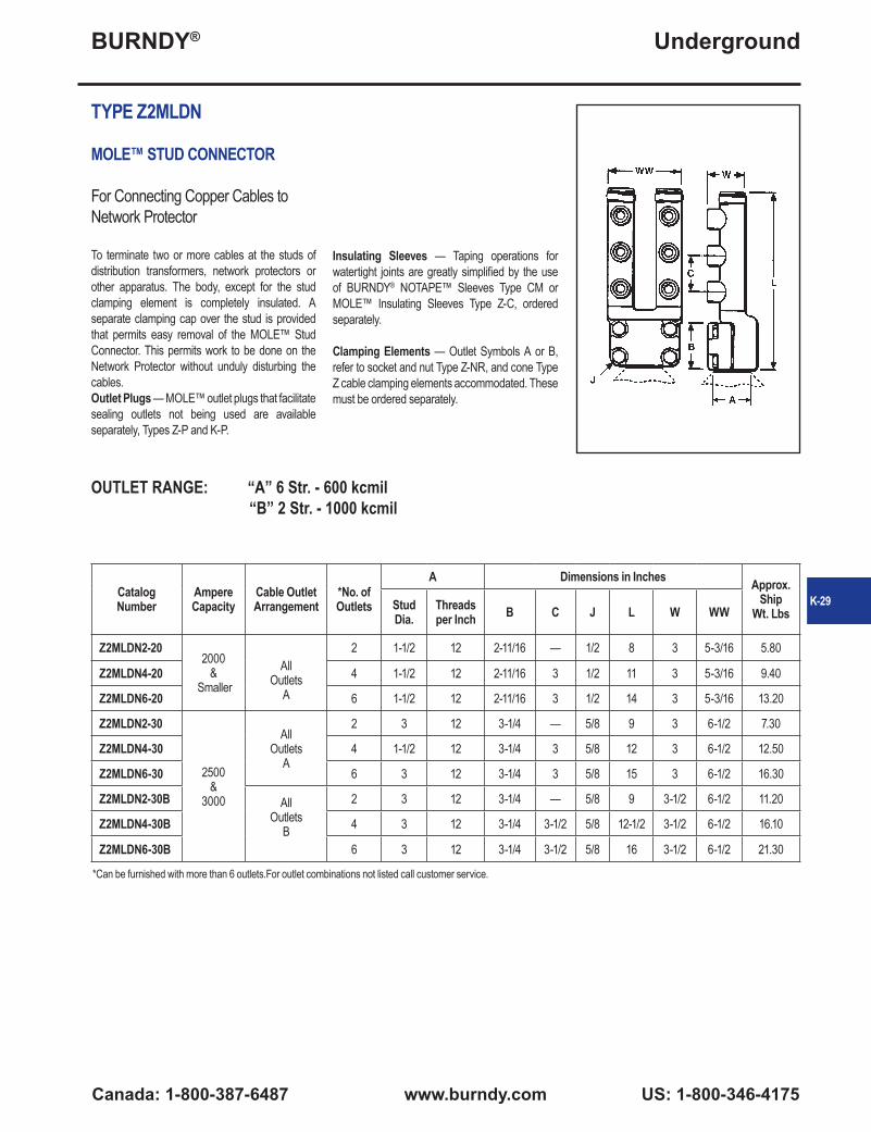
TYPE Z2MLDN
MOLE™ STUD CONNECTOR
For Connecting Copper Cables to Network Protector
To terminate two or more cables at the studs of distribution transformers, network protectors or other apparatus. The body, except for the stud clamping element is completely insulated. A separate clamping cap over the stud is provided that permits easy removal of the MOLE™ Stud Connector. This permits work to be done on the Network Protector without unduly disturbing the cables.Outlet Plugs — MOLE™ outlet plugs that facilitate sealing outlets not being used are available separately, Types Z-P and K-P.
Insulating Sleeves — Taping operations for watertight joints are greatly simplified by the use of BURNDY® NOTAPE™ Sleeves Type CM or MOLE™ Insulating Sleeves Type Z-C, ordered separately.
Clamping Elements — Outlet Symbols A or B, refer to socket and nut Type Z-NR, and cone Type Z cable clamping elements accommodated. These must be ordered separately.
Catalog Number
Ampere Capacity
Cable Outlet Arrangement
*No. of Outlets
A Dimensions in Inches Approx.Ship
Wt. LbsStud Dia.
Threads per Inch B C J L W WW
Z2MLDN2-202000
& Smaller
All Outlets
A
2 1-1/2 12 2-11/16 — 1/2 8 3 5-3/16 5.80
Z2MLDN4-20 4 1-1/2 12 2-11/16 3 1/2 11 3 5-3/16 9.40
Z2MLDN6-20 6 1-1/2 12 2-11/16 3 1/2 14 3 5-3/16 13.20
Z2MLDN2-30
2500 &
3000
All Outlets
A
2 3 12 3-1/4 — 5/8 9 3 6-1/2 7.30
Z2MLDN4-30 4 1-1/2 12 3-1/4 3 5/8 12 3 6-1/2 12.50
Z2MLDN6-30 6 3 12 3-1/4 3 5/8 15 3 6-1/2 16.30
Z2MLDN2-30B All Outlets
B
2 3 12 3-1/4 — 5/8 9 3-1/2 6-1/2 11.20
Z2MLDN4-30B 4 3 12 3-1/4 3-1/2 5/8 12-1/2 3-1/2 6-1/2 16.10
Z2MLDN6-30B 6 3 12 3-1/4 3-1/2 5/8 16 3-1/2 6-1/2 21.30
OUTLET RANGE: “A” 6 Str. - 600 kcmil “B” 2 Str. - 1000 kcmil
*Can be furnished with more than 6 outlets.For outlet combinations not listed call customer service.
K-29

BURNDY®
US: 1-800-346-4175 www.burndy.com Canada: 1-800-387-6487
Underground
TYPE ZMDN
MOLE™ STUD CONNECTOR
For Connecting Copper Cables to Network Protector
To terminate one or more cables at the studs of distribution transformers, network protectors or other apparatus. The body, except for the stud clamping element is completely insulated. A separate clamping cap over the stud is provided that permit easy removal of the MOLE™ Stud Connector. This permits work to be done on the Network Protector without unduly disturbing the cables.
Outlet Plugs — MOLE™ outlet plugs that facilitate sealing outlets not being used are available separately, Types Z-P and K-P.
Insulating Sleeves — Taping operations for watertight joints are greatly simplified by the use of BURNDY® NOTAPE™ Sleeves Type CM or MOLE™ Insulating Sleeves Type Z-C, ordered separately.
Clamping Elements — Outlet Symbols A or B, refer to socket and nut Type Z-NR, and cone Type Z cable clamping elements accommodated. These must be ordered separately.
Catalog Number
Ampere Capacity
Cable Outlet Arrangement
*No. of Outlets
A Dimensions in Inches Approx.Ship
Wt. Lbs.Stud Dia.
Threads per Inch B C J H L W
ZMDN3-20
2000 &
Smaller
All Outlets
A
3 1-1/2 12 2-11/16 3-1/2 1/2 8-1/16 11-1/2 3-7/16 14.50
ZMDN4-20 4 1-1/2 12 2-11/16 3-1/2 1/2 8-1/16 15 3-7/16 17.50
ZMDN5-20 5 1-1/2 12 2-11/16 3-1/2 1/2 8-1/16 18-1/2 3-7/16 20.50
ZMDN6-20 6 1-1/2 12 2-11/16 3-1/2 1/2 8-1/16 22 3-7/16 23.50
ZMDN3-20B
All Outlets
B
3 1-1/2 12 2-11/16 3-1/2 1/2 8-1/16 11-1/2 3-7/16 14.50
ZMDN4-20B 4 1-1/2 12 2-11/16 3-1/2 1/2 8-1/16 15 3-7/16 17.50
ZMDN5-20B 5 1-1/2 12 2-11/16 3-1/2 1/2 8-1/16 18-1/2 3-7/16 20.50
ZMDN6-20B 6 1-1/2 12 2-11/16 3-1/2 1/2 8-1/16 22 3-7/16 23.50
ZMDN3-25
2000 Through
2500
All Outlets
A
3 3 12 3-1/4 3-1/2 5/8 8-5/8 11-1/2 3-7/16 26.50
ZMDN4-25 4 3 12 3-1/4 3-1/2 5/8 8-5/8 15 3-7/16 20.50
ZMDN5-25 5 3 12 3-1/4 3-1/2 5/8 8-5/8 18-1/2 3-7/16 23.50
ZMDN6-25 6 3 12 3-1/4 3-1/2 5/8 8-5/8 22 3-7/16 26.50
OUTLET RANGE: “A” 6 Str. - 600 kcmil “B” 2 Str. - 1000 kcmil
*Can be furnished with more than 6 outlets. For outlet combinations not listed call customer service. For connectors with an odd number of outlets the odd and even split of outlets will be as indicated in the diagram.
Odd Even
K-30

BURNDY®
Canada: 1-800-387-6487 www.burndy.com US: 1-800-346-4175
Underground
TYPE ZMTDN
MOLE™ STUD CONNECTOR
For Connecting Copper Cables to Network Protector
To terminate two or more cables at the studs of distribution transformers, network protectors or other apparatus. The body, except for the stud clamping element is completely insulated. A separate clamping cap over the stud is provided that permits easy removal of the MOLE™ Stud Connector. This permits work to be done on the Network Protector without unduly disturbing the cables.
TYPE Z-P
MOLE™ OUTLET PLUGS
These plugs facilitate sealing MOLE™ outlets not being used.
Catalog Number Used On Outlet Size
Z29P A
Z34P B
Z40P C
CatalogNumber
AmpereCapacity Number of Outlets Cable Outlet
Arrangement Stud Dia.
ZMTDN815 1500 8 A 1.50"
ZMTDN1015 1500 10 A 1.50"
ZMTDN820 2000-2500 8 A 1.50"
ZMTDN81025 2000-2500 10 A 1.50"K-31
BURNDY®
US: 1-800-346-4175 www.burndy.com Canada: 1-800-387-6487
Underground
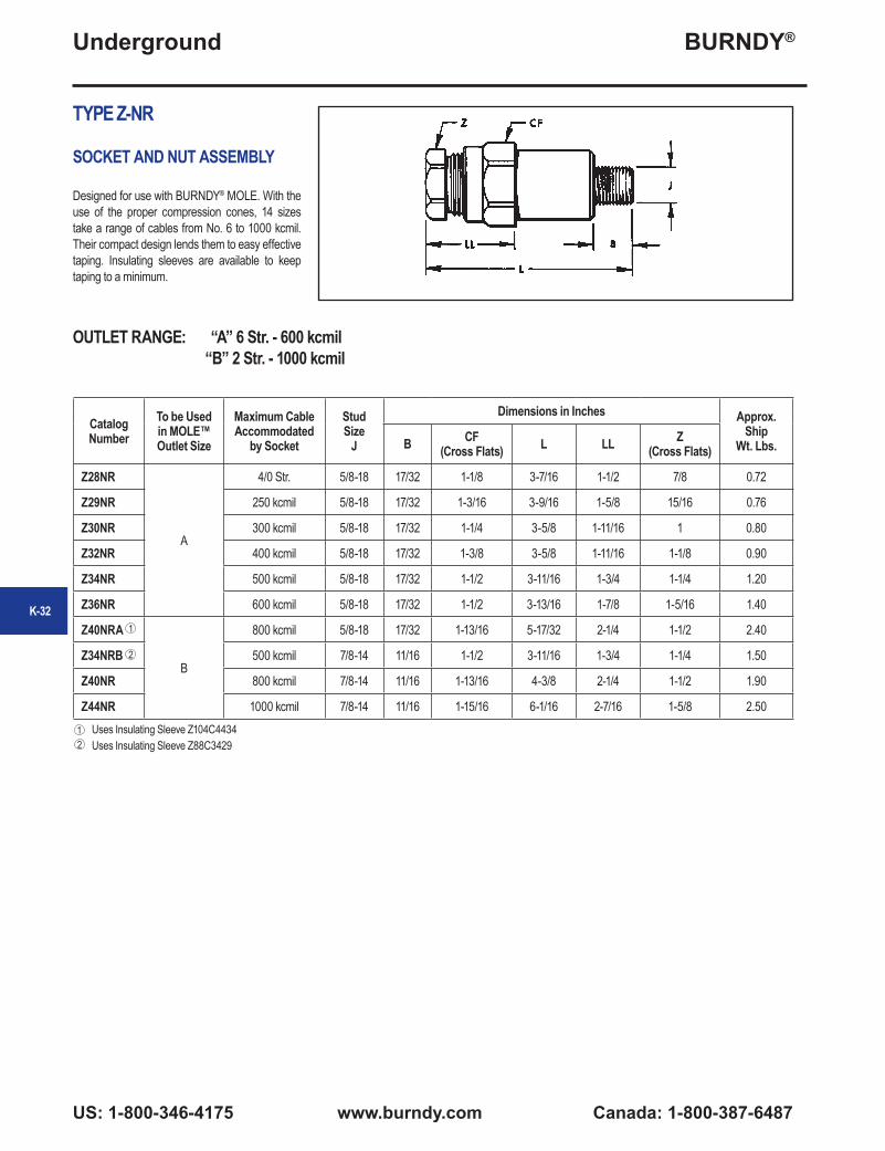
TYPE Z-NR
SOCKET AND NUT ASSEMBLY
Designed for use with BURNDY® MOLE. With the use of the proper compression cones, 14 sizes take a range of cables from No. 6 to 1000 kcmil. Their compact design lends them to easy effective taping. Insulating sleeves are available to keep taping to a minimum.
Catalog Number
To be Used in MOLE™ Outlet Size
Maximum Cable Accommodated
by Socket
Stud Size
J
Dimensions in Inches Approx. Ship
Wt. Lbs.B CF (Cross Flats) L LL Z
(Cross Flats)
Z28NR
A
4/0 Str. 5/8-18 17/32 1-1/8 3-7/16 1-1/2 7/8 0.72
Z29NR 250 kcmil 5/8-18 17/32 1-3/16 3-9/16 1-5/8 15/16 0.76
Z30NR 300 kcmil 5/8-18 17/32 1-1/4 3-5/8 1-11/16 1 0.80
Z32NR 400 kcmil 5/8-18 17/32 1-3/8 3-5/8 1-11/16 1-1/8 0.90
Z34NR 500 kcmil 5/8-18 17/32 1-1/2 3-11/16 1-3/4 1-1/4 1.20
Z36NR 600 kcmil 5/8-18 17/32 1-1/2 3-13/16 1-7/8 1-5/16 1.40
Z40NRA
B
800 kcmil 5/8-18 17/32 1-13/16 5-17/32 2-1/4 1-1/2 2.40
Z34NRB 500 kcmil 7/8-14 11/16 1-1/2 3-11/16 1-3/4 1-1/4 1.50
Z40NR 800 kcmil 7/8-14 11/16 1-13/16 4-3/8 2-1/4 1-1/2 1.90
Z44NR 1000 kcmil 7/8-14 11/16 1-15/16 6-1/16 2-7/16 1-5/8 2.50Uses Insulating Sleeve Z104C4434Uses Insulating Sleeve Z88C34292
1
1
2
OUTLET RANGE: “A” 6 Str. - 600 kcmil “B” 2 Str. - 1000 kcmil
K-32
BURNDY®
Canada: 1-800-387-6487 www.burndy.com US: 1-800-346-4175
Underground
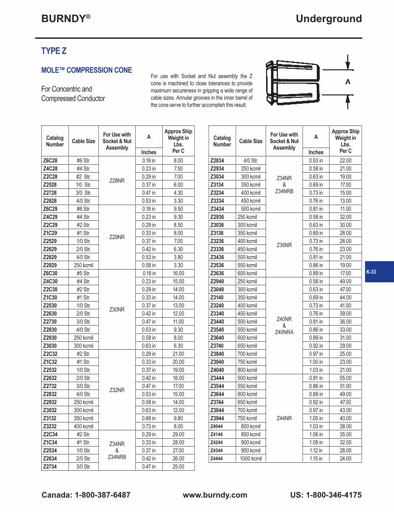
TYPE Z
MOLE™ COMPRESSION CONE
For Concentric and Compressed Conductor
Catalog Number Cable Size
For Use with Socket & Nut
Assembly
AApprox Ship
Weight in Lbs. Per CInches
Z6C28 #6 Str.
Z28NR
0.18 in 8.00Z4C28 #4 Str. 0.23 in 7.50Z2C28 #2 Str. 0.29 in 7.00Z2528 1/0 Str. 0.37 in 6.00Z2728 3/0 Str. 0.47 in 4.30Z2828 4/0 Str. 0.53 in 3.30Z6C29 #6 Str.
Z29NR
0.18 in 9.50Z4C29 #4 Str. 0.23 in 9.30Z2C29 #2 Str. 0.29 in 8.50Z1C29 #1 Str. 0.33 in 8.00Z2529 1/0 Str. 0.37 in 7.00Z2629 2/0 Str. 0.42 in 6.30Z2829 4/0 Str. 0.53 in 3.80Z2929 250 kcmil 0.58 in 3.30Z6C30 #5 Str.
Z30NR
0.18 in 16.00Z4C30 #4 Str. 0.23 in 15.00Z2C30 #2 Str. 0.29 in 14.00Z1C30 #1 Str. 0.33 in 14.00Z2530 1/0 Str. 0.37 in 13.00Z2630 2/0 Str. 0.42 in 12.00Z2730 3/0 Str. 0.47 in 11.00Z2830 4/0 Str. 0.53 in 9.30Z2930 250 kcmil 0.58 in 8.00Z3030 300 kcmil 0.63 in 6.30Z2C32 #2 Str.
Z32NR
0.29 in 21.00Z1C32 #1 Str. 0.33 in 20.00Z2532 1/0 Str. 0.37 in 19.00Z2632 2/0 Str. 0.42 in 18.00Z2732 3/0 Str. 0.47 in 17.00Z2832 4/0 Str. 0.53 in 15.00Z2932 250 kcmil 0.58 in 14.00Z3032 300 kcmil 0.63 in 12.00Z3132 350 kcmil 0.68 in 9.80Z3232 400 kcmil 0.73 in 8.00Z2C34 #2 Str.
Z34NR&
Z34NRB
0.29 in 29.00Z1C34 #1 Str. 0.33 in 28.00Z2534 1/0 Str. 0.37 in 27.00Z2634 2/0 Str. 0.42 in 26.00Z2734 3/0 Str. 0.47 in 25.00
Catalog Number Cable Size
For Use with Socket & Nut
Assembly
AApprox Ship
Weight in Lbs. Per CInches
Z2834 4/0 Str.
Z34NR&
Z34NRB
0.53 in 22.00Z2934 250 kcmil 0.58 in 21.00Z3034 300 kcmil 0.63 in 19.00Z3134 350 kcmil 0.69 in 17.00Z3234 400 kcmil 0.73 in 15.00Z3334 450 kcmil 0.76 in 13.00Z3434 500 kcmil 0.81 in 11.00Z2936 250 kcmil
Z36NR
0.58 in 32.00Z3036 300 kcmil 0.63 in 30.00Z3136 350 kcmil 0.69 in 28.00Z3236 400 kcmil 0.73 in 26.00Z3336 450 kcmil 0.76 in 23.00Z3436 500 kcmil 0.81 in 21.00Z3536 550 kcmil 0.86 in 19.00Z3636 600 kcmil 0.89 in 17.00Z2940 250 kcmil
Z40NR&
Z40NRA
0.58 in 49.00Z3040 300 kcmil 0.63 in 47.00Z3140 350 kcmil 0.69 in 44.00Z3240 400 kcmil 0.73 in 41.00Z3340 450 kcmil 0.76 in 39.00Z3440 500 kcmil 0.81 in 36.00Z3540 550 kcmil 0.86 in 33.00Z3640 600 kcmil 0.89 in 31.00Z3740 650 kcmil 0.92 in 29.00Z3840 700 kcmil 0.97 in 25.00Z3940 750 kcmil 1.00 in 23.00Z4040 800 kcmil 1.03 in 21.00Z3444 500 kcmil
Z44NR
0.81 in 55.00Z3544 550 kcmil 0.86 in 51.00Z3644 600 kcmil 0.89 in 49.00Z3744 650 kcmil 0.92 in 47.00Z3844 700 kcmil 0.97 in 43.00Z3944 750 kcmil 1.00 in 40.00Z4044 800 kcmil 1.03 in 38.00Z4144 850 kcmil 1.06 in 35.00Z4244 900 kcmil 1.09 in 32.00Z4344 950 kcmil 1.12 in 28.00Z4444 1000 kcmil 1.15 in 24.00
K-33
For use with Socket and Nut assembly the Z cone is machined to close tolerances to provide maximum secureness in gripping a wide range of cable sizes. Annular grooves in the inner barrel of the cone serve to further accomplish this result.

BURNDY®
US: 1-800-346-4175 www.burndy.com Canada: 1-800-387-6487
Underground
TYPE Z
MOLE™ COMPRESSION CONE
For Compact Conductor
For use with Socket and Nut assembly the Z cone is machined to close tolerances to provide maximum secureness in gripping a wide range of cable sizes. Annular grooves in the inner barrel of the cone serve to further accomplish this result.
Compact Stranded Copper Cable
Type Z Cone
Socket and Nut
Assembly
Compact Cable Size
Nominal Conductor Diameter
Z3C28
Z28NR
#2 0.268Z2C28 #1 0.299Z1C28 1/0 0.336Z2528 2/0 0.376Z2628 3/0 0.423Z2728 4/0 0.475Z2C29
Z29NR
#1 0.299Z1C29 1/0 0.336Z2529 2/0 0.376Z2629 3/0 0.423Z2729 40 0.475Z2829 250 kcmil 0.520Z2929 300 kcmil 0.570Z1C30
Z30NR
1/0 0.336Z2530 2/0 0.376Z2630 3/0 0.423Z2730 4/0 0.475Z2830 250 kcmil 0.520Z2930 300 kcmil 0.570Z1C32
Z32NR
1/0 0.336Z2532 2/0 0.376Z2632 3/0 0.423Z2732 4/0 0.475Z2832 250 kcmil 0.520Z2932 300 kcmil 0.570Z3232 500 kcmil 0.736Z2534
Z34NR
2/0 0.376Z2634 3/0 0.423Z2734 4/0 0.475Z2834 250 kcmil 0.520Z2934 300 kcmil 0.570Z3234 500 kcmil 0.736Z3334 550 kcmil 0.775Z3434 600 kcmil 0.813
Compact Stranded Copper Cable
Type Z Cone
Socket and Nut
Assembly
Compact Cable Size
Nominal Conductor Diameter
Z2536
Z36NR
2/0 0.376Z2636 3/0 0.423Z2736 4/0 0.475Z2836 250 kcmil 0.520Z2936 300 kcmil 0.570Z3236 500 kcmil 0.736Z3336 550 kcmil 0.775Z3436 600 kcmil 0.813Z3636 750 kcmil 0.908Z2640
Z40NR
3/0 0.423Z2740 4/0 0.475Z2840 250 kcmil 0.520Z2940 300 kcmil 0.570Z3240 500 kcmil 0.736Z3340 550 kcmil 0.775Z3440 600 kcmil 0.813Z3640 750 kcmil 0.908Z2844
Z44NR
250 kcmil 0.520Z2944 300 kcmil 0.570Z3244 500 kcmil 0.736Z3344 550 kcmil 0.775Z3444 600 kcmil 0.813Z3644 750 kcmil 0.908
K-34

BURNDY®
Canada: 1-800-387-6487 www.burndy.com US: 1-800-346-4175
Underground
TYPE ZMS
MOLE™ COUPLER
For Connecting MOLE™A compact, easy-to-tape MOLE™ Coupler for joining multiple MOLE end-to-end. Allows for expansion of underground systems by joining more MOLE to existing MOLE™ installations. Easily assembled to the end outlets of MOLE™ Types ZMT, ZMX, ZML, and ZMK. Can also be used in side outlets for other types of MOLE™
MOLE™ Outlet Size MOLE™ Coupler MOLE™ Coupler
Ampere Capacity
Dimensions in InchesApprox. Ship
Wt. Lbs.Overall LengthCross Flats
Y ZA ZMS29 1200 4-21/32 1-3/16 1-3/8 1.30B ZMS34 1600 5-7/32 1-1/2 1-3/4 2.30C ZMS40 2000 5-3/4 1-3/4 2-1/8 3.30
arrangements. The MOLE™ Coupler has a lock-nut feature which permits pre-positioning of the added MOLE™, and facilitates training of new cables. Makes an effective electrical and mechanical connection.
OUTLET RANGE: “A” (5/8") 6 Str. - 600 kcmil “B” (7/8") 2 Str. - 1000 kcmil “C” (1-1/8") 500 - 1500 kcmil
TYPE CM
NOTAPE™ MOLE™ SLEEVEThe BURNDY® NOTAPE™ MOLE™ Sleeve effectively eliminates the necessity of taping from the MOLE™ outlet to the insulation of the incoming cable. The sleeve fits snugly over the MOLE™ outlet and is held securely in place by a non-corrosive clamp. Bushings inside the sleeve are supplied to fit closely over the insulation of the cable. The other end of the assembly is clamped to the cable insulation. For rubber insulated cable two clamps are supplied.
OUTLET RANGE: “A” 6 Str. - 600 kcmil
† Diameter over rubber insulation or lead sheath to be specified by customer. ‡ Diameter over lead sheath to be specified by customer.
Bushings must be ordered separately. They are not supplied with the sleeve. The bushing inside diameter is sized in 64ths.
For oil filled cables a third clamp is provided to effect an oil-tight joint.
Sleeve & Clamps BushingTo be
Used Over Outlet Size
Type of Cable
InsulationCable Range
AccommodatedCatalog No.
Sleeve & Clamps Only
For Use Sockets & Nut Assy
Dimensions in Inches
App. Ship Wt. Ea. in
Lbs.
Catalog No. Bushing
OnlyI.D.
App. Ship Wt. Ea. in
Lbs.L O.D.
A
Rubber or Rubber-Lead #6 Str. to 600 kcmil CM29L Z28NR to
Z36NR 6-1/4 2-1/4 1.10 CMB-29R † 0.20
Paper-Lead or
Vanished Cambric
#6-4/0 Str. CM2829P Z28NR
6-1/4 2-1/4 1.10 CMB-29P ‡ 0.20
#6 AWG-250 kcmil CM2929P Z29NR#6 AWG-300 kcmil CM3029P Z3ONR#2 AWG-400 kcmil CM3229P Z32NR#2 AWG-500 kcmil CM3429P Z34NR
250-600 kcmil CM3629P Z36NR
K-35

BURNDY®
US: 1-800-346-4175 www.burndy.com Canada: 1-800-387-6487
Underground
TYPE Z-C
MOLE™ OUTLET INSULATING SLEEVE
An effective aid in insulating MOLE™ outlets to produce a secure watertight joint with a minimum of taping. Fits over the MOLE™ outlet and over the maximum outer diameter of insulated cable. The difference between the I.D. of the standard sleeve and the O.D. of the cable insulation is taken up by wrapping the cable with several turns of rubber tape. The only external taping required to effectively seal the joint is the small area at each end of the sleeve.
Catalog Number
For Use with Socket and Nut Assemblies Fig. No.
Dimensions in Inches Approx. ShipWt. in Lbs.
per C*A (Max.) L W
Z72C3029Z28NRZ29NRZ30NR
1 1-1/8 4-3/4 1-7/8 20
Z88C3429Z32NRZ34NR
Z34NRBZ36NR
1 1-3/8 5-3/16 2-1/8 30
Z104C4034 Z40NR 1 1-5/8 5-13/16 3-5/6 60
Z104C4434 Z44NRZ40NRA 2 1-5/8 7-3/16 3-5/6 70
Z144C4840Z45NRZ46NRZ47NRZ48NR
2 2-1/4 9-5/16 3-1/2 130
Fig. 1 Fig. 2
* Build up insulation of MOLE™ Joint with rubber tape to equal inner diameter of Insulating Sleeve, for insulating sleeve with inner diameter other than standard call customer service.
K-36

BURNDY®
Canada: 1-800-387-6487 www.burndy.com US: 1-800-346-4175
Underground
HYCRAB™ CONNECTORS
One of the most economical devices for connecting several cables to a common junction point is the HYCRAB™, which is essentially a bus bar with a number of compression-type connector outlets, pre-insulated to eliminate taping. Like the MOLE™, the HYCRAB™ fits into a limited space, is simple to rack, and facilitates addigin future cables.
Insert and InsulationHaving an insert similar to that of the MOLE™, the HYCRAB™, has connector outlets of the BURNDY® HYDENT™ compression type. These tubular elements are indented to the cable by BURNDY® HYPRESS™ installation tools and dies, designed to compress connector and cable together with indents of controlled depth. HYDENT™ compression connections are made quickly and easily, have relative conductivities
of 100% or higher, are electrically stable, and mechanically secure.
The HYCRAB™ is insulated by a jacket of molded rubber to resist prolonged exposure to oil or other contaminants.
InstallationInsulation fingers are rolled back to expose the tublar outlets, sufficiently spaced to allow for the convenient operation of BURNDY® HYPRESS™ compression tools. Cable ends are inserted into the outlets. Each is crimped with one or two indents, and the fingers are rolled forward again to cover the outlets. Installation is completed by taping the short space between the tip of the finger and cable insulation.
Variations and AccessoriesUninsulated HYCRAB™ connectors for joining bare neutral cables are available in the same range of sizes and number of outlets as the insulated HYCRAB™. By using reducing adapters, the HYCRAB™ can accommodate service wires as small as #6, in addition to the 4/0 or 500 kcmil cable sizes for which these connectors are ordinarily used.
TYPE YM
INSULATED HYCRAB™
A compact insulated crab joint for connecting underground cables at junction points. Two outlets, one on either side of the HYCRAB™ body are ready for immediate use. All other outlets are sealed with vulcanized rubber plugs which are easily removed when future installations are made. This unit eliminates bulky, difficult crotch taping. By using Reducing Adapters, Type Y-R the HYCRAB™ can be installed on cable sizes from #6 to 500 kcmil (e.g., use Y3428R to install 4/0 into YM4-34).
Catalog Number
Cable Size A
# of Outlets
Dimension in Inches
Installation Information
App. ShipWt. in Lbs.
HYPRESS™ & Indentor Die
# of IndentsY34BH with Y34PR
B H L M MM W Nest Die
YM4-28
4/0 Str.
4 2 3-11/16 10-3/16 — 2-3/16 1-1/8 B28D 1 1.80
YM6-28 6 2 7-9/16 10-3/16 3-7/8 2-3/16 1-1/8 B28D 1 3.00
YM8-28 8 2 9-3/4 10-3/16 3-7/8 2-3/16 1-1/8 B28D 1 4.30
YM10-28 10 2 13-1/2 8-3/4 3-1/2 2-1/2 1-1/8 B28D 1 5.50
YM12-28 12 2 16 8-3/4 3-1/2 2-1/2 1-1/8 B28D 1 6.70
YM4-34
500 kcmil
4 2-1/2 4-3/8 12-5/8 — 2-3/8 1-1/2
No Nest Die
Required.Use Indentor Only.
2 4.50
YM6-34 6 2-1/2 8-5/8 12-5/8 4-1/4 2-3/8 1-1/2 2 7.00
YM8-34 8 2-1/2 11 12-5/8 4-1/4 2-3/8 1-1/2 2 11.00
YM10-34 10 2-1/2 14-1/2 12-1/2 3-3/4 2-1/2 1-1/2 2 15.00
YM12-34 12 2-1/2 17 12-1/2 3-3/4 2-1/2 1-1/2 2 19.00
K-37
BURNDY®
US: 1-800-346-4175 www.burndy.com Canada: 1-800-387-6487
Underground
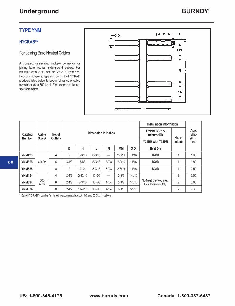
TYPE YNM
HYCRAB™
For Joining Bare Neutral Cables
A compact uninsulated multiple connector for joining bare neutral underground cables. For insulated crab joints, see HYCRAB™, Type YM. Reducing adapters, Type Y-R, permit the HYCRAB products listed below to take a full range of cable sizes from #6 to 500 kcmil. For proper installation, see table below.
Catalog Number
Cable Size A
No. of Outlets
Dimension in Inches
Installation Information
App. ShipWt. in Lbs.
HYPRESS™ & Indentor Die
No. of IndentsY34BH with Y34PR
B H L M MM O.D. Nest Die
YNM428
4/0 Str.
4 2 3-3/16 8-3/16 — 2-3/16 11/16 B28D 1 1.00
YNM628 6 3-1/8 7-1/6 8-3/16 3-7/8 2-3/16 11/16 B28D 1 1.80
YNM828 8 2 9-1/4 8-3/16 3-7/8 2-3/16 11/16 B28D 1 2.50
YNM434500 kcmil
4 2-1/2 3-15/16 10-5/8 — 2-3/8 1-1/16No Nest Die Required.
Use Indentor Only.
2 3.00
YNM634 6 2-1/2 8-3/16 10-5/8 4-1/4 2-3/8 1-1/16 2 5.00
YNM834 8 2-1/2 10-9/16 10-5/8 4-1/4 2-3/8 1-1/16 2 7.30
* Bare HYCRAB™ can be furnished to accommodate both 4/0 and 500 kcmil cables.
K-38

BURNDY®
Canada: 1-800-387-6487 www.burndy.com US: 1-800-346-4175
Underground
NETWORK PROTECTIONThe primary purpose of network protection is the controlled interruption of fault currents before damage occurs to cable insulations and associated equipment, and the elimination of unnecessary service interruptions. The limiter and fuses for network protection are closely associated wtith the connectors and are equally vital to the safe, continuous operation of an underground system. BURNDY has developed protective devices that have played a major role in reducing underground system outages and the subsequent expenses incurred in the loss of service and replacement of damaged cables. A basic objective has been the design of limiter-connector combinations that, in addition to protecting against the effects of fault currents, economize on both space and installation costs.
Limiters are designed to protect underground secondary cable from damage by fault currents of two principal kinds: high energy arcing faults and sustained faults. The arcing fault, usually of shorter duration and lesser intensity, is more common. While this type of fault may sputter briefly and then clear, some may be sustained long enough to “roast” the insulation.
A sustained fault occurs when two conductors come solidly into contact and permit the flow of heavy short-circuit currents. Without suitable protection, these fault currents are heavy enough to damage cable insulation and often produce combustible fumes accompanied by fire and explosion.
Installed at each end of cable sections, limiters have time-current characteristics designed to avoid unnecessary outages. Network protector fuses, installed in the network protector on the load side of the breaker, provide back-up protection against failure of a network protector to open on a primary fault. Coordinated characteristics of limiters and fuses provide for fault currents to be interrupted before they can cause damage, but only under predetermined time-current conditions, and only in those parts of the system where interruption is necessary.
LimitersEngineered to interrupt the circuit before cables carrying a fault current are usually damaged, limiters act to confine damage to the section of cable where the fault occurred. The limiters are designed to prevent unnecessary clearing and will
“hang on” during:1. Faults with wold clear without damaging
cable insulation2. Overloads from motor starting, load transfer
because of primary fault, or temporary overload during fault conditions
3. Overloads from loss of secondary conductors caused by clearing of other limiters
4. Reverse current flow through the network protector on primary faults
5. Faults on other secondary cables
For proper proection BURNDY® limiters are designed with time-current characteristcs approximating the insulation damage curve of the cable with which they will be used. Figure 4 shows time-current characteristic curves for a range of standard (250 volt) limiters, superimposed on insulation damage curves for several cable sizes. Although the limiter curve crosses the insulation damage curves, in practice the limiters will blow before the insulation can deteriorate. The insulation damage characteristics represent three phases equally loaded in a duct. Since low-current faults seldom affect more than one phase at a time, the rate of heat generated in the conduit is much less than for a balanced 3-phase fault, and the time to reach the damage point is appreciably longer. Practical experience confirms that limiters provide protection during low-current, as well as high-current faults.
ConstructionThe limiter is essentially a compression-type electrical connector with its center section accurately formed to provide a fusible element. This fusible element is enclosed in a molded ceramic shell and the assembly encased in an insulated sleeve.
Interrupting capacities are as follows:Standard Limiters: 30,000 amps at 250VReplaceable-Link Limiters: 20,000 amps at 250V
The protection probably lies in the fact that the fault impedance reduces the actual fault current to a value considerably less than calculated.
Replaceable-Link LimitersReplaceable-link limiters, which provide faster time-current characteristics (Figure 5), are used in smaller networks, on the fringes of larger networks, at points where radial feeders leave a network, and for fusing service cables. As its name implies, this limiter is also distinctive in that its fusible link is replaceable.
Figure 4: Current - Amperes Standard 250 Volt Limiters
Figure 5: Current in Amperes Replaceable-link Limiters
K-39
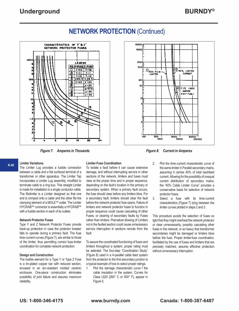
BURNDY®
US: 1-800-346-4175 www.burndy.com Canada: 1-800-387-6487
Underground
NETWORK PROTECTION (Continued)
Limiter VariationsThe Limiter Lug provides a fusible connection between a cable and a flat surfaced terminal of a transformer or other apparatus. The Limiter Tap incorporates a Limiter Lug assembly, modified to terminate cable to a ring bus. Thie straight Limiter is made for installation in a single conductor cable. The Molimiter is a Limiter designed so that one end is crimped onto a cable and the other fits the clamping element of a MOLE™ outlet. The Limiter HYCRAB™ connector is essentially a HYCRAB™ with a fusible section in each of its outlets.
Network Protector FusesType Y and Z Network Protector Fuses provide back-up protection in case the protector breaker fails to operate during a primary fault. The fuse time-current curves (Figure 7), are similar to those of the limiter, thus permitting correct fuse-limiter coordination for complete network protection.
Design and ConstructionThe fusible element for a Type Y or Type Z Fuse is a tin-plated copper bar with reduced section, encased in an arc-resistant molded ceramic enclosure. One-piece construction eliminates possibility of joint failure and assures maximum reliability.
Limiter-Fuse CoordinationTo isolate a fault before it can cause extensive damage, and without interrupting service in other sections of the network, limiters and fuses must clear at the proper time and in proper sequence, depending on the fault’s location in the primary or secondary system. When a primary fault occurs, the fuse should clear before any limiters blow. For a secondary fault, limiters should clear the fault before the network protector fuse opens. Failure of limiters and network protector fuses to function in proper sequence could cause cascading of other Fuses, or clearing of secondary faults by Fuses rather than limiters. Premature blowing of Limiters not in the faulted section could cause unnecessary service interruption in sections remote from the fault.
To assure the coordinated functioning of fuses and limiters throughout a system, proper rating must be selected. The four-step “Coordination Study” (Figure 8) used in a 4-parallel cable feed system from the protector to the first secondary junction is a typical example of how to select proper ratings.1. Plot the damage characteristic curve f the
cable insulation in the system. Curves for Class L620 (260° C or 500° F), appear in Figure 5.
2. Plot the time-current characteristic curve of the same limiter in Parallel secondary mains, assuming it carries 40% of total backfeed current. Allowing for the possibility of unequal current distribution of secondary mains, the “40% Cable Limiter Curve” provides a conservative basis for selection of network protector fuses.
3. Select a fuse with its time-current characteristics (Figure 7) lying between the limiter curves plotted in steps 2 and 3.
This procedure avoids the selection of fuses so light that they might overheat the network protector or clear unnecessarily, possibly cascading other fuses in the network; or so heavy that transformer secondaries might be damaged or limiters blow before the fuse. Proper limiter-fuse coordination, facilitated by the use of fuses and limiters that are precisely matched, assures effective protection without unnecessary interruption.
Figure 7: Amperes in Thosands Figure 8: Current in Amperes
K-40

BURNDY®
Canada: 1-800-387-6487 www.burndy.com US: 1-800-346-4175
Underground
TYPES YFS-CR ANDYFS-CP
LIMITER ASSEMBLY
With Ceramic Shell and Rubber Sleeve for Insulated Cables
The Limiter combines the functions of fuse and connector. The fusible element which is an integral part of the connector will clear faults that are great enough to cause damage to the cable insulation. However it will not clear on minor overloads of short duration. Fusing characteristics of the limiter are shown in technical section. For HYPRESS™ installation, see table below.
For Use On
Cable Size
Dimensions in Inches Installation Tooling (# Crimps)
Rubber Insulated
Cable
Paper Insulated
Cable*Max. Cable Dia. over Insulation
AL O.D.
Die Information Hydraulic
Catalog Number Die Index
Type
Y34A 750 Series, Y35, Y39
46 Series
Y45
Y48B 60 Series
YFS28CR YSF28CP 4/0 Str. 1 12-3/4 1-15/16 15
Purple Die Set — U28RT (2) U28RT (2) U28RT (2) C28R (2) L28RT
(1)Nest
IndentorA28D (1)Y34PR
U28DI (1)Y34PR
U28DI (1)Y34PR
U28DI (1)Y34PR
C28D (1)Y48PR —
YFS29CR YFS29CP 250 kcmil 1 12-3/4 1-15/16 16
Yellow Die Set — U29RT (2) U29RT (2) U29RT (2) C29R (2) L29RT
(1)Nest
IndentorA29D (2)Y34PR
U29DI (2)Y34PR
U29DI (2)Y34PR
U29DI (2)Y34PR
C29D (1)Y48PR —
YFS30CR YFS30CP 300 kcmil 1-1/8 13-1/2 2-3/16 17
White Die Set — U30RT (4) U30RT (4) U30RT (4) C30R (1) L30RT
(1)Nest
IndentorA30D (2)Y34PR
U30DI (2)Y34PR
U30DI (2)Y34PR
U30DI (2)Y34PR
C30D (2)Y48PR —
YFS31CR YFS31CP 350 kcmil 1-1/8 13-1/2 2-3/16 18
Red Die Set — U31RT (4) U31RT (4) U31RT (4) C31R (1) L31RT
(1)Nest
IndentorA31D (2)Y34PR
U31DI (2)Y34PR
U31DI (2)Y34PR
U31D1 (2)Y34PR
C31D (1)Y48PR —
YFS32CR YFS32CP 400 kcmil 1-1/8 13-1/2 2-3/16 19
Blue Die Set — U32RT (4) U32RT (4) U32RT (4) C32R (1) L32RT
(1)Nest
IndentorA32D (2)Y34PR
U32D1 (2)Y34PR
U32DI (2)Y34PR
U32DI (2)Y34PR
C32D (2)Y48PR —
YFS34CR YFS34CP 500 kcmil 1-11/32 15-7/8 2-3/8 20
Brown Die Set — U34RT (4) U34RT (4)
P34RT (4) U34RT (4) C34R (2) L34RT (2)
NestIndentor
A34D (2)Y34PR
U34D1 (2)Y34PR
U34DI (2)Y34PR
U34DI (2)Y34PR
C34D (2)Y48PR —
YFS39CR YFS39CP 750 kcmil 1-1/2 15-9/16 2-9/16 24
Black Die Set — U39RT (4) U39RT (4)
P39RT (4)U39RT (4)S39RT (4) — L39RT
(2)Nest
Indentor — — — — — —
For conductor sizes not listed call customer service. To specify a fast acting limiter in any configuration insert an “F” before the conductor number (e.g., YFSF34CR specifies a 1/2 thick limiter section).*Paper Insulated Cable - Oil Tight Cable Sockets. Y35P3 Indentor Adaptor required for Y34PR Indentor Catalog number PUADP1 Adaptor is required to use “U” type dies in the Y46 series tools Catalog number PT6515 Adaptor is required to use “U” type dies in the Y45 series tools
K-41
CERAMICSHELL
INSULATINGSLEEVE

BURNDY®
US: 1-800-346-4175 www.burndy.com Canada: 1-800-387-6487
Underground
TYPE YFS-CPL
LONG LIMITER ASSEMBLY
With Ceramic Shell and Rubber Sleeve for Paper-Lead Cables
The Long Limiter performs the same functions as the Limiter shown, Types YFS-CR and YFS-CP. It differs in that it has extra long cable sockets which are preferred by some for use on paper insuated cable. The end seams are sealed to make the sockets oil tight. Fusing characteristics of the Limiter are shown in technical section. For proper HYPRESS™ installation, see table below.
Catalog Number
Cable Size
Dimensions in Inches Installation Tooling (# Crimps)Max. Cable Dia. over
Insulation AL O.D.
Die Information HydraulicDie
IndexType
Y34A 750 Series, Y35, Y39
46 Series
Y45
Y48B 60 Series
YFS28CPL 4/0 Str. 1 12-3/4 1-15/16 15
Purple Die Set — U28RT (2) U28RT (2) U28RT (2) C28R (2) L28RT (1)
NestIndentor
A28D (1)Y34PR
U28DI (1)Y34PR
U28DI (1)Y34PR
U28DI (1)Y34PR
C28D (1)Y48PR —
YFS29CPL 250 kcmil 1 12-3/4 1-15/16 16
Yellow Die Set — U29RT (2) U29RT (2) U29RT (2) C29R (2) L29RT (1)
NestIndentor
A29D (2)Y34PR
U29DI (2)Y34PR
U29DI (2)Y34PR
U29DI (2)Y34PR
C29D (1)Y48PR —
YFS30CPL 300 kcmil 1-1/8 13-1/2 2-3/16 17
White Die Set — U30RT (4) U30RT (4) U30RT (4) C30R (1) L30RT (1)
NestIndentor
A30D (2)Y34PR
U30DI (2)Y34PR
U30DI (2)Y34PR
U30DI (2)Y34PR
C30D (2)Y48PR —
YFS31CPL 350 kcmil 1-1/8 13-1/2 2-3/16 18Red Die Set — U31RT (4) U31RT (4) U31RT (4) C31R (1) L31RT (1)
NestIndentor
A31D (2)Y34PR
U31DI (2)Y34PR
U31DI (2)Y34PR
U31D1 (2)Y34PR
C31D (1)Y48PR —
YFS32CPL 400 kcmil 1-1/8 13-1/2 2-3/16 19
Blue Die Set — U32RT (4) U32RT (4) U32RT (4) C32R (1) L32RT (1)
NestIndentor
A32D (2)Y34PR
U32D1 (2)Y34PR
U32DI (2)Y34PR
U32DI (2)Y34PR
C32D (2)Y48PR —
YFS34CPL 500 kcmil 1-11/32 15-7/8 2-3/8 20
Brown Die Set — U34RT (4) U34RT (4)
P34RT (4) U34RT (4) C34R (2) L34RT (2)
NestIndentor
A34D (2)Y34PR
U34D1 (2)Y34PR
U34DI (2)Y34PR
U34DI (2)Y34PR
C34D (2)Y48PR —
YFS39CPL 750 kcmil 1-1/2 15-9/16 2-9/16 24
Black Die Set — U39RT (4) U39RT (4)
P39RT (4)U39RT (4)S39RT (4) — L39RT (2)
NestIndentor — — — — — —
K-42
For conductor sizes not listed call customer service. To specify a fast acting limiter in any configuration insert an “F” before the conductor number (e.g., YFSF34CR specifies a 1/2 thick limiter section). Y35P3 Indentor Adaptor required for Y34PR Indentor Catalog number PUADP1 Adaptor is required to use “U” type dies in the Y46 series tools Catalog number PT6515 Adaptor is required to use “U” type dies in the Y45 series tools

BURNDY®
Canada: 1-800-387-6487 www.burndy.com US: 1-800-346-4175
Underground
TYPES YFSR, YFSP
LIMITER
For Use with Limiter Assembly
The Limiter serves the double function of a fuse and a coupler. The fusible element is an integral part of the coupler and is closely and carefully sized to insure excellent performance. Fusing characteristics of the Limiter are shown in technical section. For proper HYPRESS™ installation, see table below.
For use on Rubber
Insulated Cable
For use on Paper Insulated
Cable* Cable Size
Dimensions in Inches Installation Tooling (# Crimps)
B L O.D.
Die Information Hydraulic
Catalog Number
Catalog Number
Die Index
Type
Y34A750
Series, Y35, Y39
46 Series
Y45
Y48B 60 Series
YFSR28 YFSP28 4/0 Str. 1-3/4 in 6-3/8 11/16 15
Purple Die Set — U28RT
(2)U28RT
(2)U28RT
(2) C28R (2) L28RT (1)
NestIndentor
A28D (1)Y34PR
U28DI (1)Y34PR
U28DI (1)Y34PR
U28DI (1)Y34PR
C28D (1)Y48PR —
YFSR29 YFSP29 250 kcmil 1-7/8 in 6-3/8 3/4 16
Yellow Die Set — U29RT
(2)U29RT
(2)U29RT
(2) C29R (2) L29RT (1)
NestIndentor
A29D (2)Y34PR
U29DI (2)Y34PR
U29DI (2)Y34PR
U29DI (2)Y34PR
C29D (1)Y48PR —
YFSR30 YFSP30 300 kcmil 2 in 6-3/4 13/16 17
White Die Set — U30RT
(4)U30RT
(4)U30RT
(4) C30R (1) L30RT (1)
NestIndentor
A30D (2)Y34PR
U30DI (2)Y34PR
U30DI (2)Y34PR
U30DI (2)Y34PR
C30D (2)Y48PR —
YFSR31 YFSP31 350 kcmil 2 in 6-3/4 7/8 18
Red Die Set — U31RT
(4)U31RT
(4)U31RT
(4) C31R (1) L31RT (1)
NestIndentor
A31D (2)Y34PR
U31DI (2)Y34PR
U31DI (2)Y34PR
U31D1 (2)
Y34PRC31D (1)Y48PR —
YFSR32 YFSP32 400 kcmil 2-1/8 in 7 31/32 19
Blue Die Set — U32RT
(4)U32RT
(4)U32RT
(4) C32R (1) L32RT (1)
NestIndentor
A32D (2)Y34PR
U32D1 (2)
Y34PRU32DI (2)Y34PR
U32DI (2)Y34PR
C32D (2)Y48PR —
YFSR34 YFSP34 500 kcmil 2-7/8 in 8-3/4 1-1/16 20
Brown Die Set — U34RT
(4)
U34RT (4)
P34RT (4)
U34RT (4) C34R (2) L34RT
(2)
NestIndentor
A34D (2)Y34PR
U34D1 (2)
Y34PRU34DI (2)Y34PR
U34DI (2)Y34PR
C34D (2)Y48PR —
YFSR39 YFSP39 750 kcmil 2-7/8 in 9 1-5/16 24
Black Die Set — U39RT
(4)
U39RT (4)
P39RT (4)
U39RT (4)
S39RT (4)
— L39RT (2)
NestIndentor — — — — — —
K-43
For conductor sizes not listed call customer service. To specify a fast acting limiter in any configuration insert an “F” before the conductor number (e.g., YFSF34CR specifies a 1/2 thick limiter section).*Paper Insulated Cable - Oil Tight Cable Sockets. Y35P3 Indentor Adaptor required for Y34PR Indentor Catalog number PUADP1 Adaptor is required to use “U” type dies in the Y46 series tools Catalog number PT6515 Adaptor is required to use “U” type dies in the Y45 series tools

BURNDY®
US: 1-800-346-4175 www.burndy.com Canada: 1-800-387-6487
Underground
TYPE YFSP-L
LONG LIMITER
For Use with Long Limiter Assembly
The Long Limiter serves the same purpose as the Limiter shown above but has extra long oil tight cable sockets which may be preferred by some for use on paper insulated cables. Similarly designed to clear on overloads that will damage the insulation of the cable. Fusing characteristics of the Long Limiter are shown in technical section. For HYPRESS™ installation, see table below.
Catalog Number
Cable Size
Dimensions in Inches Installation Tooling (# Crimps)
B L O.D.
Die Information Hydraulic
Die Index
Type
Y34A750
Series, Y35, Y39
46 Series
Y45
Y48B 60 Series
YFSP28L 4/0 Str. 2-15/16 in 8-3/4 11/16 15
Purple Die Set — U28RT (2) U28RT (2) U28RT (2) C28R (2) L28RT (1)
NestIndentor
A28D (1)Y34PR
U28DI (1)Y34PR
U28DI (1)Y34PR
U28DI (1)Y34PR
C28D (1)Y48PR —
YFSP29L 250 kcmil 3-1/16 in 8-3/4 3/4 16
Yellow Die Set — U29RT (2) U29RT (2) U29RT (2) C29R (2) L29RT (1)
NestIndentor
A29D (2)Y34PR
U29DI (2)Y34PR
U29DI (2)Y34PR
U29DI (2)Y34PR
C29D (1)Y48PR —
YFSP30L 300 kcmil 3-3/8 in 9-1/2 13/16 17
White Die Set — U30RT (4) U30RT (4) U30RT (4) C30R (1) L30RT (1)
NestIndentor
A30D (2)Y34PR
U30DI (2)Y34PR
U30DI (2)Y34PR
U30DI (2)Y34PR
C30D (2)Y48PR —
YFSP31L 350 kcmil 3-3/8 in 9-1/2 7/8 18
Red Die Set — U31RT (4) U31RT (4) U31RT (4) C31R (1) L31RT (1)
NestIndentor
A31D (2)Y34PR
U31DI (2)Y34PR
U31DI (2)Y34PR
U31D1 (2)Y34PR
C31D (1)Y48PR —
YFSP32L 400 kcmil 3-3/8 in 9-1/2 31/32 19
Blue Die Set — U32RT (4) U32RT (4) U32RT (4) C32R (1) L32RT (1)
NestIndentor
A32D (2)Y34PR
U32D1 (2)Y34PR
U32DI (2)Y34PR
U32DI (2)Y34PR
C32D (2)Y48PR —
YFSP34L 500 kcmil 4-3/16 in 11-3/8 1-1/16 20
Brown Die Set — U34RT (4) U34RT (4)
P34RT (4) U34RT (4) C34R (2) L34RT (2)
NestIndentor
A34D (2)Y34PR
U34D1 (2)Y34PR
U34DI (2)Y34PR
U34DI (2)Y34PR
C34D (2)Y48PR —
YFSP39L 750 kcmil 4-3/16 in 11-5/8 1-5/16 24
Black Die Set — U39RT (4) U39RT (4)
P39RT (4)U39RT (4)S39RT (4) — L39RT (2)
NestIndentor — — — — — —
For conductor sizes not listed call customer service. To specify a fast acting limiter in any configuration insert an “F” before the conductor number (e.g., YFSF34CR specifies a 1/2 thick limiter section). Y35P3 Indentor Adaptor required for Y34PR Indentor Catalog number PUADP1 Adaptor is required to use “U” type dies in the Y46 series tools Catalog number PT6515 Adaptor is required to use “U” type dies in the Y45 series tools
K-44
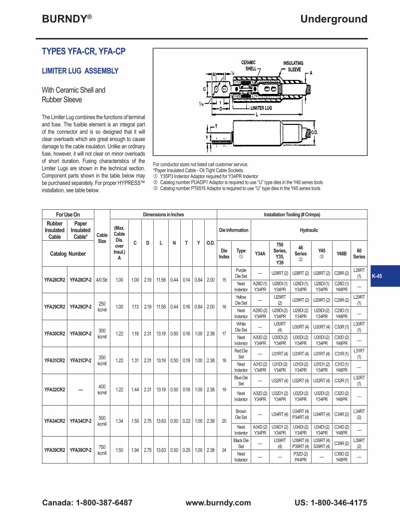
BURNDY®
Canada: 1-800-387-6487 www.burndy.com US: 1-800-346-4175
Underground
TYPES YFA-CR, YFA-CP
LIMITER LUG ASSEMBLY
With Ceramic Shell andRubber Sleeve
The Limiter Lug combines the functions of terminal and fuse. The fusible element is an integral part of the connector and is so designed that it will clear overloads which are great enough to cause damage to the cable insulation. Unlike an ordinary fuse, however, it will not clear on minor overloads of short duration. Fusing characteristics of the Limiter Lugs are shown in the technical section. Component parts shown in the table below may be purchased separately. For proper HYPRESS™ installation, see table below.
For Use On
Cable Size
Dimensions in Inches Installation Tooling (# Crimps)Rubber
Insulated Cable
Paper Insulated
Cable*(Max. Cable Dia. over
Insul.) A
C D L N T Y O.D.
Die Information Hydraulic
Catalog Number Die Index
Type
Y34A750
Series, Y35, Y39
46 Series
Y45
Y48B 60 Series
YFA28CR2 YFA28CP-2 4/0 Str. 1.00 1.00 2.19 11.56 0.44 0.14 0.84 2.00 15
Purple Die Set — U28RT (2) U28RT (2) U28RT (2) C28R (2) L28RT
(1)Nest
IndentorA28D (1)Y34PR
U28DI (1)Y34PR
U28DI (1)Y34PR
U28DI (1)Y34PR
C28D (1)Y48PR —
YFA29CR2 YFA29CP-2 250 kcmil 1.00 1.13 2.19 11.56 0.44 0.16 0.84 2.00 16
Yellow Die Set — U29RT
(2) U29RT (2) U29RT (2) C29R (2) L29RT (1)
NestIndentor
A29D (2)Y34PR
U29DI (2)Y34PR
U29DI (2)Y34PR
U29DI (2)Y34PR
C29D (1)Y48PR —
YFA30CR2 YFA30CP-2 300 kcmil 1.22 1.19 2.31 13.19 0.50 0.16 1.00 2.38 17
White Die Set — U30RT
(4) U30RT (4) U30RT (4) C30R (1) L30RT (1)
NestIndentor
A30D (2)Y34PR
U30DI (2)Y34PR
U30DI (2)Y34PR
U30DI (2)Y34PR
C30D (2)Y48PR —
YFA31CR2 YFA31CP-2 350 kcmil 1.22 1.31 2.31 13.19 0.50 0.19 1.00 2.38 18
Red Die Set — U31RT (4) U31RT (4) U31RT (4) C31R (1) L31RT
(1)Nest
IndentorA31D (2)Y34PR
U31DI (2)Y34PR
U31DI (2)Y34PR
U31D1 (2)Y34PR
C31D (1)Y48PR —
YFA32CR2 — 400 kcmil 1.22 1.44 2.31 13.19 0.50 0.19 1.00 2.38 19
Blue Die Set — U32RT (4) U32RT (4) U32RT (4) C32R (1) L32RT
(1)
NestIndentor
A32D (2)Y34PR
U32D1 (2)Y34PR
U32DI (2)Y34PR
U32DI (2)Y34PR
C32D (2)Y48PR —
YFA34CR2 YFA34CP-2 500 kcmil 1.34 1.50 2.75 13.63 0.50 0.22 1.00 2.38 20
Brown Die Set — U34RT (4) U34RT (4)
P34RT (4) U34RT (4) C34R (2) L34RT (2)
NestIndentor
A34D (2)Y34PR
U34D1 (2)Y34PR
U34DI (2)Y34PR
U34DI (2)Y34PR
C34D (2)Y48PR —
YFA39CR2 YFA39CP-2 750 kcmil 1.50 1.94 2.75 13.63 0.50 0.25 1.00 2.38 24
Black Die Set — U39RT
(4)U39RT (4)P39RT (4)
U39RT (4)S39RT (4) C39R (2) L39RT
(2)Nest
Indentor — — P32D (2)P44PR — C39D (2)
Y48PR —
For conductor sizes not listed call customer service. *Paper Insulated Cable - Oil Tight Cable Sockets. Y35P3 Indentor Adaptor required for Y34PR Indentor Catalog number PUADP1 Adaptor is required to use “U” type dies in the Y46 series tools Catalog number PT6515 Adaptor is required to use “U” type dies in the Y45 series tools
K-45
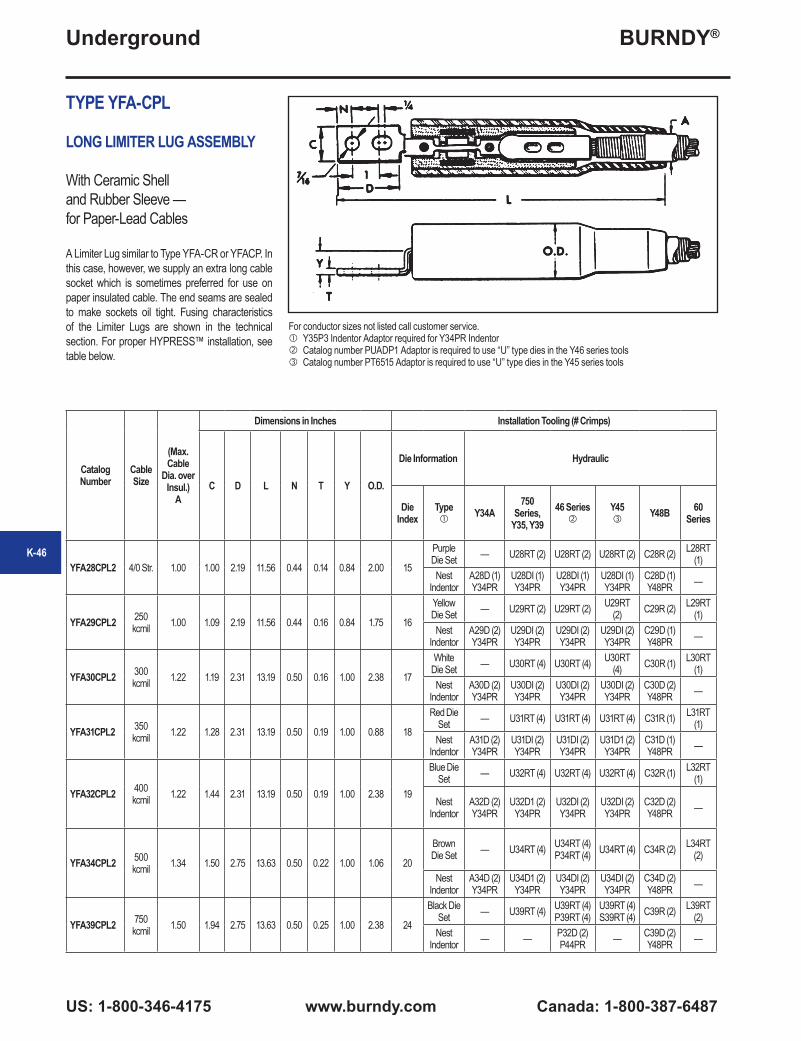
BURNDY®
US: 1-800-346-4175 www.burndy.com Canada: 1-800-387-6487
Underground
TYPE YFA-CPL
LONG LIMITER LUG ASSEMBLY
With Ceramic Shell and Rubber Sleeve —for Paper-Lead Cables
A Limiter Lug similar to Type YFA-CR or YFACP. In this case, however, we supply an extra long cable socket which is sometimes preferred for use on paper insulated cable. The end seams are sealed to make sockets oil tight. Fusing characteristics of the Limiter Lugs are shown in the technical section. For proper HYPRESS™ installation, see table below.
Catalog Number
Cable Size
(Max. Cable
Dia. over Insul.)
A
Dimensions in Inches Installation Tooling (# Crimps)
C D L N T Y O.D.
Die Information Hydraulic
Die Index
Type
Y34A750
Series, Y35, Y39
46 Series
Y45
Y48B 60 Series
YFA28CPL2 4/0 Str. 1.00 1.00 2.19 11.56 0.44 0.14 0.84 2.00 15
Purple Die Set — U28RT (2) U28RT (2) U28RT (2) C28R (2) L28RT
(1)Nest
IndentorA28D (1)Y34PR
U28DI (1)Y34PR
U28DI (1)Y34PR
U28DI (1)Y34PR
C28D (1)Y48PR —
YFA29CPL2 250 kcmil 1.00 1.09 2.19 11.56 0.44 0.16 0.84 1.75 16
Yellow Die Set — U29RT (2) U29RT (2) U29RT
(2) C29R (2) L29RT (1)
NestIndentor
A29D (2)Y34PR
U29DI (2)Y34PR
U29DI (2)Y34PR
U29DI (2)Y34PR
C29D (1)Y48PR —
YFA30CPL2 300 kcmil 1.22 1.19 2.31 13.19 0.50 0.16 1.00 2.38 17
White Die Set — U30RT (4) U30RT (4) U30RT
(4) C30R (1) L30RT (1)
NestIndentor
A30D (2)Y34PR
U30DI (2)Y34PR
U30DI (2)Y34PR
U30DI (2)Y34PR
C30D (2)Y48PR —
YFA31CPL2 350 kcmil 1.22 1.28 2.31 13.19 0.50 0.19 1.00 0.88 18
Red Die Set — U31RT (4) U31RT (4) U31RT (4) C31R (1) L31RT
(1)Nest
IndentorA31D (2)Y34PR
U31DI (2)Y34PR
U31DI (2)Y34PR
U31D1 (2)Y34PR
C31D (1)Y48PR —
YFA32CPL2 400 kcmil 1.22 1.44 2.31 13.19 0.50 0.19 1.00 2.38 19
Blue Die Set — U32RT (4) U32RT (4) U32RT (4) C32R (1) L32RT
(1)
NestIndentor
A32D (2)Y34PR
U32D1 (2)Y34PR
U32DI (2)Y34PR
U32DI (2)Y34PR
C32D (2)Y48PR —
YFA34CPL2 500 kcmil 1.34 1.50 2.75 13.63 0.50 0.22 1.00 1.06 20
Brown Die Set — U34RT (4) U34RT (4)
P34RT (4) U34RT (4) C34R (2) L34RT (2)
NestIndentor
A34D (2)Y34PR
U34D1 (2)Y34PR
U34DI (2)Y34PR
U34DI (2)Y34PR
C34D (2)Y48PR —
YFA39CPL2 750 kcmil 1.50 1.94 2.75 13.63 0.50 0.25 1.00 2.38 24
Black Die Set — U39RT (4) U39RT (4)
P39RT (4)U39RT (4)S39RT (4) C39R (2) L39RT
(2)Nest
Indentor — — P32D (2)P44PR — C39D (2)
Y48PR —
K-46
For conductor sizes not listed call customer service. Y35P3 Indentor Adaptor required for Y34PR Indentor Catalog number PUADP1 Adaptor is required to use “U” type dies in the Y46 series tools Catalog number PT6515 Adaptor is required to use “U” type dies in the Y45 series tools

BURNDY®
Canada: 1-800-387-6487 www.burndy.com US: 1-800-346-4175
Underground
K-47
TYPES YFAR, YFAP
LIMITER LUG
For Use with Limiter Lug Assembly
The Limiter Lug incorporates an accurately determined fusible section as an integral part with its terminal end. The fusible section is so selected that it wil prevent the cable from roasting or damage from a short circuit, although it will not clear on minor overloads of short duration not harmful to cable insulation. For proper HYPRESS™ installation, see table below.
For Use On
Cable Size
Dimensions in Inches Installation Tooling (# Crimps)Rubber
Insulated Cable
Paper Insulated
Cable*B C D L N T Y O.D.
Die Informa-tion Hydraulic
Catalog Number Die Index
Type
Y34A750
Series, Y35, Y39
46 Series
Y45
Y48B 60 Series
YFAR282 YFAP282 4/0 Str. 1.81 1.00 2.19 8.22 0.44 0.14 0.89 0.70 15
Purple Die Set — U28RT (2) U28RT (2) U28RT (2) C28R (2) L28RT
(1)Nest
IndentorA28D (1)Y34PR
U28DI (1)Y34PR
U28DI (1)Y34PR
U28DI (1)Y34PR
C28D (1)Y48PR —
YFAR292 YFAP292 250 kcmil 1.81 1.09 2.19 8.22 0.44 0.16 0.91 0.76 16
Yellow Die Set — U29RT (2) U29RT (2) U29RT (2) C29R (2) L29RT
(1)Nest
IndentorA29D (2)Y34PR
U29DI (2)Y34PR
U29DI (2)Y34PR
U29DI (2)Y34PR
C29D (1)Y48PR —
YFAR302 YFAP302 300 kcmil 1.94 1.19 2.31 8.88 0.50 0.16 1.07 0.83 17
White Die Set — U30RT (4) U30RT (4) U30RT (4) C30R (1) L30RT
(1)Nest
IndentorA30D (2)Y34PR
U30DI (2)Y34PR
U30DI (2)Y34PR
U30DI (2)Y34PR
C30D (2)Y48PR —
YFAR312 YFAP312 350 kcmil 1.94 1.28 2.31 8.88 0.50 0.18 1.08 0.89 18
Red Die Set — U31RT (4) U31RT (4) U31RT (4) C31R (1) L31RT
(1)Nest
IndentorA31D (2)Y34PR
U31DI (2)Y34PR
U31DI (2)Y34PR
U31D1 (2)Y34PR
C31D (1)Y48PR —
YFAR322 YFAP322 400 kcmil 2.06 1.38 2.31 9.12 0.50 0.19 1.10 0.97 19
Blue Die Set — U32RT (4) U32RT (4) U32RT (4) C32R (1) L32RT
(1)Nest
IndentorA32D (2)Y34PR
U32D1 (2)Y34PR
U32DI (2)Y34PR
U32DI (2)Y34PR
C32D (2)Y48PR —
YFAR342 YFAP342 500 kcmil 2.44 1.54 2.75 10.00 0.50 0.23 1.11 0.97 20
Brown Die Set — U34RT (4) U34RT (4)
P34RT (4) U34RT (4) C34R (2) L34RT (2)
NestIndentor
A34D (2)Y34PR
U34D1 (2)Y34PR
U34DI (2)Y34PR
U34DI (2)Y34PR
C34D (2)Y48PR —
YFAR392 YFAP392 750 kcmil 2.44 1.91 2.75 10.00 0.50 0.26 1.14 1.34 24
Black Die Set — U39RT (4) U39RT (4)
P39RT (4)U39RT (4)S39RT (4) C39R (2) L39RT
(2)Nest
Indentor — — P32D (2)P44PR — C39D (2)
Y48PR —
For conductor sizes not listed call customer service. *Paper Insulated Cable - Oil Tight Cable Sockets. Y35P3 Indentor Adaptor required for Y34PR Indentor Catalog number PUADP1 Adaptor is required to use “U” type dies in the Y46 series tools Catalog number PT6515 Adaptor is required to use “U” type dies in the Y45 series tools

BURNDY®
US: 1-800-346-4175 www.burndy.com Canada: 1-800-387-6487
Underground
TYPE YFAP-L
LONG LIMITER LUG
For Use with Limiter Lug Assembly
Similar to Limiter Lug Types YFAR and YFAP, except that this type provides a long oil tight cable socket, preferred by some users of paper-insulated cables. Fusing characteristics shown in technical section. For HYPRESS™ installation, see table below.
Catalog Number
Cable Size
Dimensions in Inches Installation Tooling (# Crimps)
Die Information Hydraulic
B C D L N T Y O.D. Die Index
Type
Y34A750
Series, Y35, Y39
46 Series
Y45
Y48B 60 Series
YFAP28L2 4/0 Str. 3.50 1.00 2.19 10.44 0.44 0.14 0.89 0.69 15
Purple Die Set — U28RT (2) U28RT (2) U28RT (2) C28R (2) L28RT
(1)Nest
IndentorA28D (1)Y34PR
U28DI (1)Y34PR
U28DI (1)Y34PR
U28DI (1)Y34PR
C28D (1)Y48PR —
YFAP29L2 250 kcmil 3.56 1.12 2.18 10.44 0.44 0.16 0.89 0.75 16
Yellow Die Set — U29RT (2) U29RT (2) U29RT (2) C29R (2) L29RT
(1)Nest
IndentorA29D (2)Y34PR
U29DI (2)Y34PR
U29DI (2)Y34PR
U29DI (2)Y34PR
C29D (1)Y48PR —
YFAP30L2 300 kcmil 3.63 1.18 2.31 11.19 0.50 0.16 1.10 0.76 17
White Die Set — U30RT (4) U30RT (4) U30RT (4) C30R (1) L30RT
(1)Nest
IndentorA30D (2)Y34PR
U30DI (2)Y34PR
U30DI (2)Y34PR
U30DI (2)Y34PR
C30D (2)Y48PR —
YFAP31L2 350 kcmil 3.63 1.38 2.31 11.38 0.50 0.18 1.08 0.82 18
Red Die Set — U31RT (4) U31RT (4) U31RT (4) C31R (1) L31RT (1)
NestIndentor
A31D (2)Y34PR
U31DI (2)Y34PR
U31DI (2)Y34PR
U31D1 (2)Y34PR
C31D (1)Y48PR —
YFAP32L2 400 kcmil 3.75 1.38 2.31 11.50 0.50 0.19 1.10 0.89 19
Blue Die Set — U32RT (4) U32RT (4) U32RT (4) C32R (1) L32RT
(1)Nest
IndentorA32D (2)Y34PR
U32D1 (2)Y34PR
U32DI (2)Y34PR
U32DI (2)Y34PR
C32D (2)Y48PR —
YFAP34L2 500 kcmil 4.13 1.54 2.75 12.25 0.50 0.23 1.11 0.98 20
Brown Die Set — U34RT (4) U34RT (4)
P34RT (4) U34RT (4) C34R (2) L34RT (2)
NestIndentor
A34D (2)Y34PR
U34D1 (2)Y34PR
U34DI (2)Y34PR
U34DI (2)Y34PR
C34D (2)Y48PR —
YFAP39L2 750 kcmil 4.13 1.91 2.75 12.31 0.50 0.27 1.14 1.20 24
Black Die Set — U39RT (4) U39RT (4)
P39RT (4)U39RT (4)S39RT (4) C39R (2) L39RT
(2)Nest
Indentor — — P32D (2)P44PR — C39D (2)
Y48PR —
K-48
For conductor sizes not listed call customer service. Y35P3 Indentor Adaptor required for Y34PR Indentor Catalog number PUADP1 Adaptor is required to use “U” type dies in the Y46 series tools Catalog number PT6515 Adaptor is required to use “U” type dies in the Y45 series tools
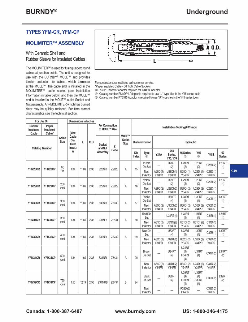
BURNDY®
Canada: 1-800-387-6487 www.burndy.com US: 1-800-346-4175
Underground
K-49
For conductor sizes not listed call customer service. *Paper Insulated Cable - Oil Tight Cable Sockets. Y35P3 Indentor Adaptor required for Y34PR Indentor Catalog number PUADP1 Adaptor is required to use “U” type dies in the Y46 series tools Catalog number PT6515 Adaptor is required to use “U” type dies in the Y45 series tools
TYPES YFM-CR, YFM-CP
MOLIMITER™ ASSEMBLY
With Ceramic Shell andRubber Sleeve for Insulated Cables
The MOLIMITER™ is used for fusing underground cables at junction points. The unit is designed for use with the BURNDY® MOLE™ and provides Limiter protection for cables. which terminate at the MOLE™. The cable end is installed in the MOLIMITER™ cable socket (see Installation Information in table below) and then the MOLE™ end is installed in the MOLE™ outlet Socket and Nut assembly. Any MOLIMITER which has burned clear may be quickly replaced. For time current characteristics see the technical section.
For Use On
Cable Size
Dimensions in InchesFor Connection to MOLE™ Use
MOLE™ Outlet Size
Installation Tooling (# Crimps)Rubber Insulated
Cable
Paper Insulated
Cable* (Max. Cable Dia. Over Insul.)
A
L O.D.
Catalog NumberSocket and Nut
AssemblyZ
Cone
Die Information Hydraulic
Die Index
Type
Y34A750
Series, Y35, Y39
46 Series
Y45
Y48B 60 Series
YFM28CR YFM28CP 4/0 Str. 1.34 11.69 2.38 Z28NR Z2828 A 15
Purple Die Set — U28RT
(2)U28RT
(2)U28RT
(2) C28R (2) L28RT (1)
NestIndentor
A28D (1)Y34PR
U28DI (1)Y34PR
U28DI (1)Y34PR
U28DI (1)Y34PR
C28D (1)Y48PR —
YFM29CR YFM29CP 250 kcmil 1.34 11.69 2.38 Z29NR Z2929 A 16
Yellow Die Set — U29RT
(2)U29RT
(2)U29RT
(2) C29R (2) L29RT (1)
NestIndentor
A29D (2)Y34PR
U29DI (2)Y34PR
U29DI (2)Y34PR
U29DI (2)Y34PR
C29D (1)Y48PR —
YFM30CR YFM30CP 300 kcmil 1.34 11.69 2.38 Z30NR Z3030 A 17
White Die Set — U30RT
(4)U30RT
(4)U30RT
(4) C30R (1) L30RT (1)
NestIndentor
A30D (2)Y34PR
U30DI (2)Y34PR
U30DI (2)Y34PR
U30DI (2)Y34PR
C30D (2)Y48PR —
YFM31CR YFM31CP 350 kcmil 1.34 11.69 2.38 Z31NR Z3131 A 18
Red Die Set — U31RT (4) U31RT
(4)U31RT
(4) C31R (1) L31RT (1)
NestIndentor
A31D (2)Y34PR
U31DI (2)Y34PR
U31DI (2)Y34PR
U31D1 (2)Y34PR
C31D (1)Y48PR —
YFM32CR YFM32CP 400 kcmil 1.34 11.69 2.38 Z32NR Z3232 A 19
Blue Die Set — U32RT
(4)U32RT
(4)U32RT
(4) C32R (1) L32RT (1)
NestIndentor
A32D (2)Y34PR
U32D1 (2)Y34PR
U32DI (2)Y34PR
U32DI (2)Y34PR
C32D (2)Y48PR —
YFM34CR YFM34CP 500 kcmil 1.34 11.69 2.38 Z34NR Z3434 A 20
Brown Die Set — U34RT
(4)
U34RT (4)
P34RT (4)
U34RT (4) C34R (2) L34RT
(2)
NestIndentor
A34D (2)Y34PR
U34D1 (2)Y34PR
U34DI (2)Y34PR
U34DI (2)Y34PR
C34D (2)Y48PR —
YFM39CR YFM39CP 750 kcmil 1.50 12.19 2.56 Z34NRB Z3434 B 24
Black Die Set — U39RT
(4)
U39RT (4)
P39RT (4)
U39RT (4)
S39RT (4)
C39R (2) L39RT (2)
NestIndentor — — P32D (2)
P44PR — C39D (2)Y48PR —
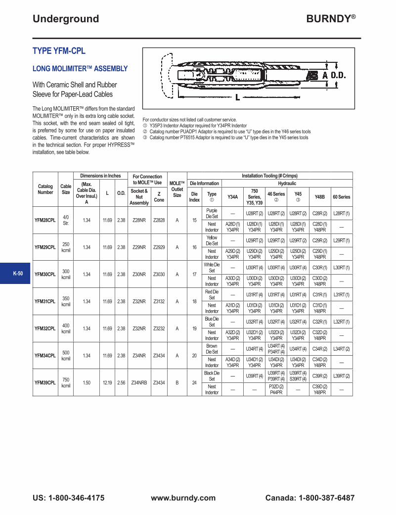
BURNDY®
US: 1-800-346-4175 www.burndy.com Canada: 1-800-387-6487
Underground
TYPE YFM-CPL
LONG MOLIMITER™ ASSEMBLY
With Ceramic Shell and Rubber Sleeve for Paper-Lead Cables
The Long MOLIMITER™ differs from the standard MOLIMITER™ only in its extra long cable socket. This socket, with the end seam sealed oil tight, is preferred by some for use on paper insulated cables. Time-current characteristics are shown in the technical section. For proper HYPRESS™ installation, see table below.
Catalog Number
Cable Size
Dimensions in Inches For Connection to MOLE™ Use MOLE™
Outlet Size
Installation Tooling (# Crimps)(Max.
Cable Dia. Over Insul.)
AL O.D.
Die Information HydraulicSocket &
Nut Assembly
Z Cone
Die Index
Type
Y34A750
Series, Y35, Y39
46 Series
Y45
Y48B 60 Series
YFM28CPL 4/0 Str. 1.34 11.69 2.38 Z28NR Z2828 A 15
Purple Die Set — U28RT (2) U28RT (2) U28RT (2) C28R (2) L28RT (1)
NestIndentor
A28D (1)Y34PR
U28DI (1)Y34PR
U28DI (1)Y34PR
U28DI (1)Y34PR
C28D (1)Y48PR —
YFM29CPL 250 kcmil 1.34 11.69 2.38 Z29NR Z2929 A 16
Yellow Die Set — U29RT (2) U29RT (2) U29RT (2) C29R (2) L29RT (1)
NestIndentor
A29D (2)Y34PR
U29DI (2)Y34PR
U29DI (2)Y34PR
U29DI (2)Y34PR
C29D (1)Y48PR —
YFM30CPL 300 kcmil 1.34 11.69 2.38 Z30NR Z3030 A 17
White Die Set — U30RT (4) U30RT (4) U30RT (4) C30R (1) L30RT (1)
NestIndentor
A30D (2)Y34PR
U30DI (2)Y34PR
U30DI (2)Y34PR
U30DI (2)Y34PR
C30D (2)Y48PR —
YFM31CPL 350 kcmil 1.34 11.69 2.38 Z32NR Z3132 A 18
Red Die Set — U31RT (4) U31RT (4) U31RT (4) C31R (1) L31RT (1)
NestIndentor
A31D (2)Y34PR
U31DI (2)Y34PR
U31DI (2)Y34PR
U31D1 (2)Y34PR
C31D (1)Y48PR —
YFM32CPL 400 kcmil 1.34 11.69 2.38 Z32NR Z3232 A 19
Blue Die Set — U32RT (4) U32RT (4) U32RT (4) C32R (1) L32RT (1)
NestIndentor
A32D (2)Y34PR
U32D1 (2)Y34PR
U32DI (2)Y34PR
U32DI (2)Y34PR
C32D (2)Y48PR —
YFM34CPL 500 kcmil 1.34 11.69 2.38 Z34NR Z3434 A 20
Brown Die Set — U34RT (4) U34RT (4)
P34RT (4) U34RT (4) C34R (2) L34RT (2)
NestIndentor
A34D (2)Y34PR
U34D1 (2)Y34PR
U34DI (2)Y34PR
U34DI (2)Y34PR
C34D (2)Y48PR —
YFM39CPL 750 kcmil 1.50 12.19 2.56 Z34NRB Z3434 B 24
Black Die Set — U39RT (4) U39RT (4)
P39RT (4)U39RT (4)S39RT (4) C39R (2) L39RT (2)
NestIndentor — — P32D (2)
P44PR — C39D (2)Y48PR —
For conductor sizes not listed call customer service. Y35P3 Indentor Adaptor required for Y34PR Indentor Catalog number PUADP1 Adaptor is required to use “U” type dies in the Y46 series tools Catalog number PT6515 Adaptor is required to use “U” type dies in the Y45 series tools
K-50
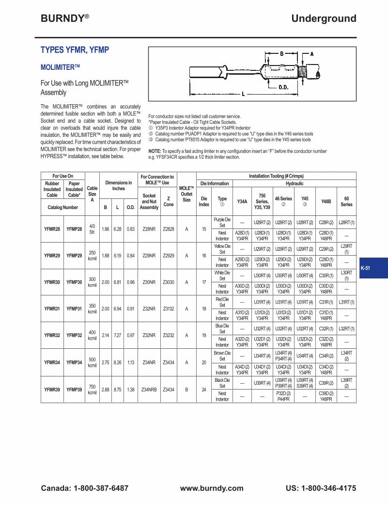
BURNDY®
Canada: 1-800-387-6487 www.burndy.com US: 1-800-346-4175
Underground
For conductor sizes not listed call customer service. *Paper Insulated Cable - Oil Tight Cable Sockets. Y35P3 Indentor Adaptor required for Y34PR Indentor Catalog number PUADP1 Adaptor is required to use “U” type dies in the Y46 series tools Catalog number PT6515 Adaptor is required to use “U” type dies in the Y45 series tools
NOTE: To specify a fast acting limiter in any configuration insert an “F” before the conductor number e.g. YFSF34CR specifies a 1/2 thick limiter section.
TYPES YFMR, YFMP
MOLIMITER™
For Use with Long MOLIMITER™ Assembly
The MOLIMITER™ combines an accurately determined fusible section with both a MOLE™ Socket end and a cable socket. Designed to clear on overloads that would injure the cable insulation, the MOLIMITER™ may be easily and quickly replaced. For time current characteristics of MOLIMITER see the technical section. For proper HYPRESS™ installation, see table below.
For Use On
Cable Size
A
Dimensions in Inches
For Connection to MOLE™ Use
MOLE™ Outlet Size
Installation Tooling (# Crimps)Rubber
Insulated Cable
Paper Insulated
Cable*
Die Information Hydraulic
Socket and Nut
AssemblyZ
ConeDie
IndexType
Y34A750
Series, Y35, Y39
46 Series
Y45
Y48B 60 SeriesCatalog Number B L O.D.
YFMR28 YFMP28 4/0 Str. 1.86 6.28 0.83 Z28NR Z2828 A 15
Purple Die Set — U28RT (2) U28RT (2) U28RT (2) C28R (2) L28RT (1)
NestIndentor
A28D (1)Y34PR
U28DI (1)Y34PR
U28DI (1)Y34PR
U28DI (1)Y34PR
C28D (1)Y48PR —
YFMR29 YFMP29 250 kcmil 1.88 6.19 0.84 Z29NR Z2929 A 16
Yellow Die Set — U29RT (2) U29RT (2) U29RT (2) C29R (2) L29RT
(1)Nest
IndentorA29D (2)Y34PR
U29DI (2)Y34PR
U29DI (2)Y34PR
U29DI (2)Y34PR
C29D (1)Y48PR —
YFMR30 YFMP30 300 kcmil 2.00 6.81 0.96 Z30NR Z3030 A 17
White Die Set — U30RT (4) U30RT (4) U30RT (4) C30R (1) L30RT
(1)Nest
IndentorA30D (2)Y34PR
U30DI (2)Y34PR
U30DI (2)Y34PR
U30DI (2)Y34PR
C30D (2)Y48PR —
YFMR31 YFMP31 350 kcmil 2.00 6.94 0.91 Z32NR Z3132 A 18
Red Die Set — U31RT (4) U31RT (4) U31RT (4) C31R (1) L31RT (1)
NestIndentor
A31D (2)Y34PR
U31DI (2)Y34PR
U31DI (2)Y34PR
U31D1 (2)Y34PR
C31D (1)Y48PR —
YFMR32 YFMP32 400 kcmil 2.14 7.27 0.97 Z32NR Z3232 A 19
Blue Die Set — U32RT (4) U32RT (4) U32RT (4) C32R (1) L32RT (1)
NestIndentor
A32D (2)Y34PR
U32D1 (2)Y34PR
U32DI (2)Y34PR
U32DI (2)Y34PR
C32D (2)Y48PR —
YFMR34 YFMP34 500 kcmil 2.75 8.26 1.13 Z34NR Z3434 A 20
Brown Die Set — U34RT (4) U34RT (4)
P34RT (4) U34RT (4) C34R (2) L34RT (2)
NestIndentor
A34D (2)Y34PR
U34D1 (2)Y34PR
U34DI (2)Y34PR
U34DI (2)Y34PR
C34D (2)Y48PR —
YFMR39 YFMP39 750 kcmil 2.88 8.75 1.38 Z34NRB Z3434 B 24
Black Die Set — U39RT (4) U39RT (4)
P39RT (4)U39RT (4)S39RT (4) C39R (2) L39RT
(2)Nest
Indentor — — P32D (2)P44PR — C39D (2)
Y48PR —
K-51
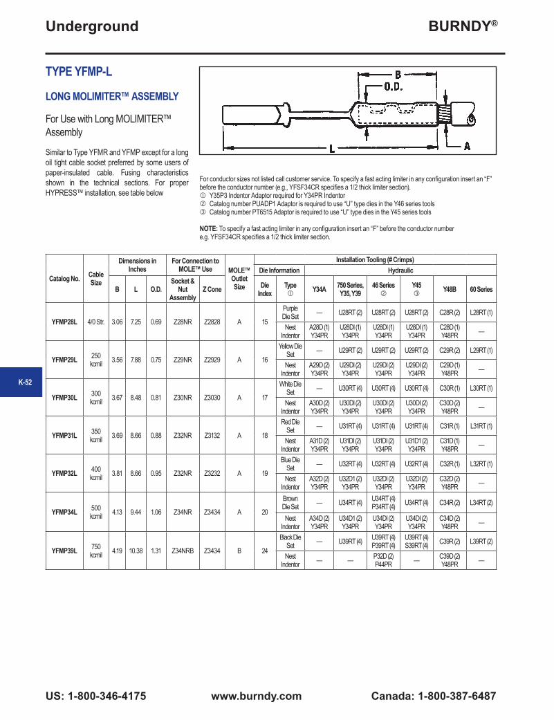
BURNDY®
US: 1-800-346-4175 www.burndy.com Canada: 1-800-387-6487
Underground
K-52
TYPE YFMP-L
LONG MOLIMITER™ ASSEMBLY
For Use with Long MOLIMITER™ Assembly
Similar to Type YFMR and YFMP except for a long oil tight cable socket preferred by some users of paper-insulated cable. Fusing characteristics shown in the technical sections. For proper HYPRESS™ installation, see table below
Catalog No. Cable Size
Dimensions in Inches
For Connection to MOLE™ Use MOLE™
Outlet Size
Installation Tooling (# Crimps)Die Information Hydraulic
B L O.D.Socket &
Nut Assembly
Z Cone Die Index
Type
Y34A 750 Series, Y35, Y39
46 Series
Y45
Y48B 60 Series
YFMP28L 4/0 Str. 3.06 7.25 0.69 Z28NR Z2828 A 15
Purple Die Set — U28RT (2) U28RT (2) U28RT (2) C28R (2) L28RT (1)
NestIndentor
A28D (1)Y34PR
U28DI (1)Y34PR
U28DI (1)Y34PR
U28DI (1)Y34PR
C28D (1)Y48PR —
YFMP29L 250 kcmil 3.56 7.88 0.75 Z29NR Z2929 A 16
Yellow Die Set — U29RT (2) U29RT (2) U29RT (2) C29R (2) L29RT (1)
NestIndentor
A29D (2)Y34PR
U29DI (2)Y34PR
U29DI (2)Y34PR
U29DI (2)Y34PR
C29D (1)Y48PR —
YFMP30L 300 kcmil 3.67 8.48 0.81 Z30NR Z3030 A 17
White Die Set — U30RT (4) U30RT (4) U30RT (4) C30R (1) L30RT (1)
NestIndentor
A30D (2)Y34PR
U30DI (2)Y34PR
U30DI (2)Y34PR
U30DI (2)Y34PR
C30D (2)Y48PR —
YFMP31L 350 kcmil 3.69 8.66 0.88 Z32NR Z3132 A 18
Red Die Set — U31RT (4) U31RT (4) U31RT (4) C31R (1) L31RT (1)
NestIndentor
A31D (2)Y34PR
U31DI (2)Y34PR
U31DI (2)Y34PR
U31D1 (2)Y34PR
C31D (1)Y48PR —
YFMP32L 400 kcmil 3.81 8.66 0.95 Z32NR Z3232 A 19
Blue Die Set — U32RT (4) U32RT (4) U32RT (4) C32R (1) L32RT (1)
NestIndentor
A32D (2)Y34PR
U32D1 (2)Y34PR
U32DI (2)Y34PR
U32DI (2)Y34PR
C32D (2)Y48PR —
YFMP34L 500 kcmil 4.13 9.44 1.06 Z34NR Z3434 A 20
Brown Die Set — U34RT (4) U34RT (4)
P34RT (4) U34RT (4) C34R (2) L34RT (2)
NestIndentor
A34D (2)Y34PR
U34D1 (2)Y34PR
U34DI (2)Y34PR
U34DI (2)Y34PR
C34D (2)Y48PR —
YFMP39L 750 kcmil 4.19 10.38 1.31 Z34NRB Z3434 B 24
Black Die Set — U39RT (4) U39RT (4)
P39RT (4)U39RT (4)S39RT (4) C39R (2) L39RT (2)
NestIndentor — — P32D (2)
P44PR — C39D (2)Y48PR —
For conductor sizes not listed call customer service. To specify a fast acting limiter in any configuration insert an “F” before the conductor number (e.g., YFSF34CR specifies a 1/2 thick limiter section). Y35P3 Indentor Adaptor required for Y34PR Indentor Catalog number PUADP1 Adaptor is required to use “U” type dies in the Y46 series tools Catalog number PT6515 Adaptor is required to use “U” type dies in the Y45 series tools
NOTE: To specify a fast acting limiter in any configuration insert an “F” before the conductor number e.g. YFSF34CR specifies a 1/2 thick limiter section.

BURNDY®
Canada: 1-800-387-6487 www.burndy.com US: 1-800-346-4175
Underground
K-53
TYPE VYFT
LIMITER TAP ASSEMBLY
For Insulated Cables
The Limiter Tap is suitable for making Limiter connections to a cable ring bus in a manhole or transformer vault. It can be installed on oilimpregnated, paper insulated, or rubber insulated cable. Fusing characteristics of the Limiter are the same as Type YFA shown in the technical section. The rubber sleeve and insulating hood reduce taping to a minimum. Catalog Numbers shown include hoods. If no hood is required, eliminate one “C” from the Catalog Number. Replaceable Link Limiter Taps can be ordered. For proper HYPRESS™ installation, see table below.Paper-Lead Cables If a long cable socket is preferred for use on paper insulated cable add
For Use on Rubber
Insulated Cable
For Use on Paper Insulated
Cable-Oil Tight Cable
SocketA Run AA Tap
Dimensions in InchesInstallation Information
App.ShipWt. in Lbs.
HYPRESS™ &Indentor Die
No. of
IndentsB Max. Cable
Dia. Over Insul.
BB Max. Cable
Dia. Over Insul.
H L Y O.D.Y34BH with Y34PR
Catalog No. Catalog No. Nest Die
VYFT3428CCR VYFT3428CCP 500 kcmil 4/0 Str. 1.09 1.00 4.00 12.19 1.75 1.94 B28D 1 2.20VYFT3434CCR VYFT3434CCP 500 kcmil 500 kcmil 1.09 1.34 4.00 14.19 1.75 2.38
No Nest Die Req’d.
2 3.50VYFT3934CCR VYFT3934CCP 750 kcmil 500 kcmil 1.31 1.34 4.00 14.19 1.75 2.38 2 3.70VYFT4434CCR VYFT4434CCP 1000 kcmil 500 kcmil 1.08 1.34 4.13 14.19 2.09 2.38 2 4.00
To specify a fast acting limiter in any configuration insert an “F” before the conductor number (e.g., YFSF34CR specifies a 1/2 thick limiter section).
“L” to the catalog number (e.g., VYFT3428CCP becomes VYFT3428CCPL).
TYPE NYFT
LIMITER TEE TAP
For Rubber or Paper Insulated Cables
The NYFT Limiter is similar to Type VYFT except the run conductor is clamped with a four bolt cap and the Limiter Tap is removable by means of a socket and nut assembly. The Limiter current characteristics are the same as Type YFA shown in the technical section.
For Use on Rubber
Insulated Cable
For Use on Paper Insulated
Cable-Oil Tight Cable
SocketA Run AA Tap
Dimensions in Inches
Installation Information
App.ShipWt. in Lbs.
HYPRESS™ & Indentor Die
No. of Indents
B Max. Cable Dia. Over Insul.
BB Max. Cable Dia. Over Insul. H L O.D.
Y34BH with Y34PRCatalog No. Catalog No. Nest Die
NYFT3434CCR NYFT3434CCP 500 kcmil 500 kcmil 1.89 1.25 2.91 16.78 2.41 No Nest Die Req’d. 2 2.20

BURNDY®
US: 1-800-346-4175 www.burndy.com Canada: 1-800-387-6487
Underground
TYPE LYS
REPLACEABLE LINK LIMITER
With Ceramic Shell and Rubber Sleeve for Insulated Cables
The Replaceable Link Limiter incorporates the functions of both fuse and coupler. For use with rubber and paper-insulated cable, it is designed to facilitate rapid and inexpensive replacement of Limiter Links upon clearing. It also permits, if desired, the use of a Link rated for a lower ampere capacity than supplied with our standard Limiter. For proper HYPRESS™ installation, see table below.
Catalog Number
Cable Size
**(Max. Cable
Dia. Over Insul. Inches)
A
Number of Indents in Cable Socket
* Link Supplied Installation Information
No. of Indents Installation Die Index Number
Ampere Capacity
Catalog Number
LYS4CC #4 Str. 0.50
1
75A LF1010
1
95
LYS2CC #2 Str.
0.75
100ALF1014 97
LYS1CC #1 Str. LF1014 98
LYS25C 1/0 Str.150A
LF1025 99
LYS26C 2/0 Str. LF1025 100
LYS27C 3/0 Str.
1.00
200A LF2019 101
LYS28C 4/0 Str.250A
LF2027 15
LYS29C 250 kcmil LF2027 16
LYS30C 300 kcmil
1.25 2
300ALF2038
2
17
LYS31C 350 kcmil LF2038 18
LYS32C 400 kcmil400A LF2065
19
LYS34C 500 kcmil 20
* Fuse link supplied is selected on the basis of a minimum blowing current of approximately twice the NEC rubber insulated cable rating. Refer to Time Current curves shown and specify if another size is desired.
** The standard end bushing supplied is for maximum cable insulation diameters as shown. Compact cable will require a bushing with a smaller inside diameter to accommodate the smaller insulation diameter of the cable. If other than standard bushing is required, contact customer service.
To specify a fast acting limiter in any configuration insert a “F” before the conductor number (e.g., YFSF34CR specifies a 1/2 thick limiter section).
K-54

BURNDY®
Canada: 1-800-387-6487 www.burndy.com US: 1-800-346-4175
Underground
K-55
TYPE LYM
REPLACEABLE LINK MOLIMITER™
With Ceramic Shell and Rubber Sleeve for Insulated Cables
The Replaceable Link MOLIMITER™ is used to fuse underground cables at junction points with the BURNDY® MOLE. The “Replaceable Link” feature permits the selection of one of several links. In addition, the replacement of links that have burned clear is both rapid and inexpensive. For use with both rubber and paper insulated cables. The MOLE™ end of the MOLIMITER™ is installed in the MOLE™ Socket and Nut Assembly, while the cable socket end is HYPRESS™ installed, see table below for proper installation.
Catalog Number
Cable Size
**(Max.Cable
Dia. Over Insul.
Inches) A
Number of
Indents in Cable Socket
* Link SuppliedFor Connection to
MOLE™ Use Installation Information
Socket & Nut
AssemblyZ Cone
No. of Indents
Installation Die Index Number
Ampere Capacity
Catalog Number
Catalog Number
Catalog Number
LYM2CC 2 Str.
0.75
1
100ALF1014
Z28NR Z28281
97
LYM1CC 1 Str. LF1014 98
LYM25C 1/0 Str.150A
LF1025 99
LYM26C 2/0 Str. LF1025 100
LYM27C 3/0 Str.
1.00
200A LF2019 101
LYM28C 4/0 Str.250A
LF2027 15
LYM29C 250 kcmil LF2027 Z29NR Z2929 16
LYM30C 300 kcmil
1.25 2
300ALF2038 Z30NR Z3030
2
17
LYM31C 350 kcmil LF2038 Z32NR Z3132 18
LYM32C 400 kcmil400A
LF2065 Z32NR Z3232 19
LYM34C 500 kcmil LF2065 Z34NR Z3434 20
* Fuse link supplied is selected on the basis of a mini-mum blowing current of approximately twice the NEC rubber insulated cable rating. Refer to Time Current curves shown and specify if another size is desired.
** The standard end bushing supplied is for maximum cable insulation diameters as shown. Compact cable will require a bushing with a smaller inside diameter to accommodate the smaller insulation diameter of the cable. If other than standard bushing is required, contact customer service.

BURNDY®
US: 1-800-346-4175 www.burndy.com Canada: 1-800-387-6487
Underground
TYPE LF
LIMITER LINK
For Use with All Replaceable Limiters
Made of pure copper, the Limiter Link is controlled dimensionally to close tolerances to maintain accurate fusing chracteristics. Refer to Time-Current Characteristic curve shown below and specify rating desired. The Limiter Link is supplied enclosed in a shell with heatproof chamber to confine and break the arc created by fusing.
*Catalog Number Ampere Capacity App. Ship Wt. in Lbs.LF1006 50A 0.08LF1010 75A 0.08LF1014 100A 0.08LF1025 150A 0.08LF2019 200A 0.09LF2027 250A 0.09LF2038 300A 0.11LF2065 400A 0.12LF2108 500A 0.15
* For use with LYS and LYM.
Current in AmperesTime-Current Fusing Characteristics of Type LF Limiter Links
The nominal current ratings of these Limiter Links are approximately one-half the minimum currents required to clear the fuses. The gneral slope and shape of the curves are similar to those of the time-current curves of the Limiters. The Type LF Limiter Links are made of pure copper with
dimensions carefully controlled in order to maintain accurate fusing characteristics.
K-56

BURNDY®
Canada: 1-800-387-6487 www.burndy.com US: 1-800-346-4175
Underground
K-57
TYPE LYBASEH
LIMITER BASE
For Use with all Replaceable Limiters
A heat resisting, high impact, molded phenolic base for mounting HYDENT™ Cable lugs or MOLIMITER™-lugs. The bases are supplied with bolts fitted in place with retaining rings, enabling the lugs to be easily assembled to BURNDY® Replaceable Limiter Links. They may be purchased separately for use with all Replaceable Limiters.
Catalog Number For Use with App. Ship Wt. in Lbs.
LYBASEHLYM
0.32LYS
TYPE LYS34P2
LIMITER SLEEVE
For Use With Replaceable Limiters
A molded sleeve for insulating the Replaceable Limiter and MOLIMITER™ assemblies. Similar to other component parts, the insulating sleeves may be purchased separately. These sleeves are used in conjunction with the LYS-P6 bushings.
Catalog Number For Use with App. Ship Wt. in Lbs.
LYS34P2LYS
1.20LYM
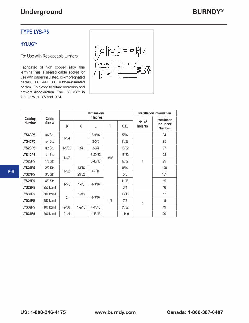
BURNDY®
US: 1-800-346-4175 www.burndy.com Canada: 1-800-387-6487
Underground
TYPE LYS-P5
HYLUG™
For Use with Replaceable Limiters
Fabricated of high copper alloy, this terminal has a sealed cable socket for use with paper insulated, oil-impregnated cables as well as rubber-insulated cables. Tin plated to retard corrosion and prevent discoloration. The HYLUG™ is for use with LYS and LYM.
Catalog Number
Cable Size A
Dimensions in Inches
Installation Information
No. of Indents
Installation Tool Index NumberB C L T O.D.
LYS6CP5 #6 Str.1-1/4
3/4
3-9/16
3/16
5/16
1
94
LYS4CP5 #4 Str. 3-5/8 11/32 95
LYS2CP5 #2 Str. 1-9/32 3-3/4 13/32 97
LYS1CP5 #1 Str.1-3/8
3-29/32 15/32 98
LYS25P5 1/0 Str. 3-15/16 17/32 99
LYS26P5 2/0 Str.1-1/2
13/164-1/16
9/16 100
LYS27P5 3/0 Str. 29/32 5/8 101
LYS28P5 4/0 Str.1-5/8 1-1/8 4-3/16
11/16 15
LYS29P5 250 kcmil
1/4
3/4 16
LYS30P5 300 kcmil2
1-3/84-9/16
13/16
2
17
LYS31P5 350 kcmil
1-9/16
7/8 18
LYS32P5 400 kcmil 2-1/8 4-11/16 31/32 19
LYS34P5 500 kcmil 2-1/4 4-13/16 1-1/16 20
K-58

BURNDY®
Canada: 1-800-387-6487 www.burndy.com US: 1-800-346-4175
Underground
K-59
TYPE LYM34P3
BUSHING
For Use with Replaceable Limiters
Type LYM34P3 is for assembly of Replaceable MOLIMITERS™ to the MOLE™ outlet. It fills the space between Limiter sleeve and the MOLE™ outlet to allow easy taping.
Catalog Number For Use with MOLE™ Outlet
SizeApp. Ship Wt.
in Lbs.
LYM34P3LYM
A 0.01LZM
TYPE LYS-P6
BUSHING
For Use with Replaceable Limiters
The LYS-P6 bushing is designed to fit closely over the cable insulation when used with the LYS34P2 Limiter sleeve. It fills the space between the Limiter sleeve and cable. The tapered bushing facilitates taping at installation.
Catalog Number
(Max. Cable Dia. Over Insul.) A For Use with App. Ship Wt.
in Lbs.LYS32P6 1/2
LYSLYM
0.19LYS48P6 3/4 0.19LYS64P6 1 0.16LYS80P6 1-1/4 0.12

BURNDY®
US: 1-800-346-4175 www.burndy.com Canada: 1-800-387-6487
Underground
TYPES Y, Z
NETWORK PROTECTOR FUSES AND CERAMIC ENCLOSURES
Type Z Network Protector Fuses are designed to coordinate with the fusible sections of the Limiters as well as the Protector characteristic itself. A Ceramic enclosure is designed especially to form an arcing chamber for these fuses. The ZH50C Enclosure is designed with high temperature glass observation windows to allow for easy viewing of the fusing element. The hole spacings in the tongues of these fuses are such that they will fit standard Network Protectors. See Time Current characteristic curve below. The Fuse element and the housing must be purchased separately.
Fuse Designation Catalog Number Transformer Full Load (Normal) Amperes
CeramicEnclosureY-Fuse
Fig. 1App. Ship. Wt. in Lbs.
Z-Fuse Fig.2
App. Ship. Wt. in Lbs.
Y-7.5 0.45 Z-7.5 0.95 400
ZH50C
Y-11 0.46 Z-11 0.96 600Y-15 0.48 Z-15 0.98 800
Y-22.5 0.50 Z-22.5 1.00 1200Y-25 0.63 Z-25 1.13 1333— 0.75 Z-30 1.25 1600
Y-37.5 0.78 Z-37.5 1.28 2000— — Z-44 1.29 2500
Y-50 0.80 Z-50 1.30 3000
K-60

BURNDY®
Canada: 1-800-387-6487 www.burndy.com US: 1-800-346-4175
Underground
K-61
NYT
T-CONNECTOR
Cable Run — Cable Tap
A “T” connector designed to provide a clamp type element on the run and a permanent HYPRESS™ connection on the tap. Recommended for use on ring buses or for applications where occasional
Catalog Number
Conductor Size Fig. No.
Dimensions in Inches
Installation Information
App. Ship. Wt. in Lbs.
HYPRESS™ & Indentor DieNo. of
IndentsY34B with Y34PR
Run A Tap AA B BB H J L Nest DieNYT282C
4/0 AWG
2/0 AWG 1 1-3/8 1-1/4 1-3/8 3/8 3-3/16 B2CD 1 1.50NYT2825 1/0 1 1-3/8 1-3/8 1-3/8 3/8 4 B25D 1 1.50NYT2826 2/0 AWG 1 1-3/8 1-1/2 1-3/8 3/8 4-1/8 B26D 1 1.50NYT2828 4/0 AWG 2 2 1-5/8 1-3/8 3/8 4-5/16 B28D 1 2.20NYT292C
250 kcmil
2/0 AWG 1 1-3/8 1-1/4 1-7/16 3/8 3-3/16 B2CD 1 1.50NYT2925 1/0 1 1-3/8 1-3/8 1-7/16 3/8 4-1/16 B25D 1 1.50NYT2926 2/0 AWG 1 1-3/8 1-1/2 1-7/16 3/8 4-3/16 B26D 1 1.50NYT2928 4/0 AWG 2 2 1-5/8 1-7/16 3/8 4-3/8 B28D 1 2.20NYT2929 250 kcmil 2 2 1-5/8 1-7/16 3/8 4-7/16 B29D 1 2.20NYT3125
350 kcmil
1/0 1 1-3/8 1-3/8 1-1/2 3/8 4-1/8 B25D 1 1.50NYT3126 2/0 AWG 1 1-3/8 1-1/2 1-1/2 3/8 4-5/16 B26D 1 1.50NYT3128 4/0 AWG 2 2 1-5/8 1-1/2 3/8 4-1/2 B28D 1 2.20NYT3129 250 kcmil 2 2 1-5/8 1-1/2 3/8 4-9/16 B29D 1 2.20NYT3131 350 kcmil 2 2 2 1-1/2 3/8 5 B31D 2 2.50NYT3426
500 kcmil
2/0 AWG 1 1-3/8 1-1/2 1-5/8 3/8 4-7/16 B26D 1 1.70NYT3428 4/0 AWG 2 2 1-5/8 1-5/8 3/8 4-5/8 B28D 1 2.50NYT3429 250 kcmil 2 2 1-5/8 1-5/8 3/8 4-5/8 B29D 1 2.50NYT3431 350 kcmil 2 2 2 1-5/8 3/8 5-1/16 B31D 2 2.50
NYT3434 500 kcmil 2 2 2-1/4 1-5/8 3/8 5-3/8 No Nest Die Req’d. 2 2.50
NYT3926
750 kcmil
2/0 AWG 1 1-3/8 1-1/2 1-7/8 3/8 4-5/8 B26D 1 1.70NYT3928 4/0 AWG 2 2 1-5/8 1-7/8 3/8 4-13/16 B28D 1 2.50NYT3929 250 kcmil 2 2 1-5/8 1-7/8 3/8 4-13/16 B29D 1 2.50NYT3931 350 kcmil 2 2 2 1-7/8 3/8 5-1/4 B31D 2 2.50
NYT3934 500 kcmil 2 2 2-1/4 1-7/8 3/8 5-9/16 No Nest Die Req’d 2 2.70
NYT3939 750 kcmil 2 2 2-7/8 1-7/8 3/8 6-1/4 — 2 3.00NYT4426
1000 kcmil
2/0 AWG 1 1-3/8 1-1/2 2-1/8 3/8 4-3/4 B26D 1 1.70NYT4428 4/0 AWG 2 2 1-5/8 2-1/8 3/8 4-15/16 B28D 1 2.50NYT4429 250 kcmil 2 2 1-5/8 2-1/8 3/8 5 B29D 1 2.50NYT4431 350 kcmil 2 2 2 2-1/8 3/8 5-7/16 B31D 2 2.50
NYT4434 500 kcmil 2 2 2-1/4 2-1/8 3/8 5-3/4 No Nest Die Req’d. 2 2.70
NYT4439 750 kcmil 2 2 2-7/8 2-1/4 3/8 6-3/8 — 2 3.00
NYT4444 1000 kcmil 2 2-11/16 3 2-5/16 1/2 7 — 2 3.20
NYT4628
1500 kcmil
4/0 AWG 2 2 1-5/8 2-11/16 3/8 5-3/8 B28D 1 4.70NYT4629 250 kcmil 2 2 1-5/8 2-11/16 3/8 5-7/16 B29D 1 4.70NYT4631 350 kcmil 2 2 2 2-11/16 3/8 5-7/8 B31D 2 4.70
NYT4634 500 kcmil 2 2 2-1/4 2-11/16 3/8 6-3/16 No Nest Die Req’d. 2 4.70
NYT4639 750 kcmil 2 2 2-7/8 2-11/16 3/8 6-3/4 — 2 5.20NYT4644 1000 kcmil 2 2 3 2-3/4 1/2 7-1/8 — 2 7.50NYT4646 1500 kcmil 2 2-11/16 3-3/16 2-3/4 1/2 7-11/16 — 2 8.00
disconnects from the run conductor are desired without disturbing the tap connection. Tin plated. For proper installation of tap cable, see table below.
Figure 1 Figure 2

BURNDY®
US: 1-800-346-4175 www.burndy.com Canada: 1-800-387-6487
Underground
HIGH CAPACITY LIMITER - 200,000 AMPERES AT 600 VOLTSThe BURNDY® High Capacity Limiter is designed to economically protect electrical distribution systems from the destructive effect of high energy faults. The increasing number of 600 volt secondary network installations for industrial and commercial applications demand a cable limiter that can safely interrupt 200,000 amperes (symmetrical available) and one that will also completely coordinate with the higher voltage network protector fuses.
Available fault currents as high as 200,000 amperes rms at 600 volts across the fusible elements have been interrupted during tests on the BURNDY® High Capacity Limiter. The power factor during these tests was less than 15%, thereby imposing the most difficult clearing conditions. No external disturbance is experienced upon clearing falt currents from the “float” value to 200,000 amperes. The quartz tiller absorbs the intense energy generated by interrupting the fault current. The quartz fuses into tubular fulgurites, with a high dielectric strength, and forms an insulating barrier between the melted link sections. This action prevents restrike of the internal arc. The rugged aluminum housing and cast epoxy end seals provide a vessel that completely contains the developed energy.
The carefully developed time-current characteristcs and rigid manufacturing tolerances assure proper coordination with the network protector fuses and the insulaiton damage characteristics of 4/0, 250, 350, 500 kcmil and 750 cable.
The High Capacity Limiter is available in four variations to accommodate a variety of installation practices. The Type HYS cable sockets at both ends, which allow for indenting to the cable ends with a hydraulic BURNDY® HYPRESS™. The HYA has an off-set lug on one end which permits back-to-back mounting on bus bar. They HYA also allows cable to installation with no off-set.
For those installations where BURNDY® MOLE™ connections are used for manhole junctions or transformer vault buses, the Type HYM permits a replaceable connection of the limiter director to the MOLE™ outlet at one end and a compression cable connection at the other.
Modern electrical distribution systems require low cost protection to safeguard costly equipment and quickly isolate faults, so that the undamaged portions of the system may function normally. BURNDY® High Capacity Limiters assure positive, economical protection when installed in properly designed systems.
NOTE: Today’s fault currents are growing. If you need higher fault current ratings, please contact the factory.
K-62

BURNDY®
Canada: 1-800-387-6487 www.burndy.com US: 1-800-346-4175
Underground
K-63
Catalog Number
Cable Size
Fig. No.
A B D E J L M P R Die Index Die
No. of Crimps per EndIn mm In mm In mm In mm In mm In mm In mm In mm In mm
HYAO_28 4/0 1 8.87 225 1.44 37 1.12 28 1.75 44 3.62 92 0.96 24 — — — — 0.68 17 15 U28RT 2HYAO_29 250 kcmil 1 9.00 229 1.44 37 1.12 28 1.88 48 3.62 92 0.96 24 — — — — 0.75 19 16 U29RT 2HYAO_31 350 kcmil 1 9.12 232 1.62 41 1.12 28 2.00 51 3.62 92 0.96 24 — — — — 0.88 22 18 U31RT 4HYAO_34 500 kcmil 1 10.00 254 1.88 48 1.62 41 2.88 73 3.62 92 1.19 30 — — — — 1.05 27 20 U34RT 4HYAO_39 750 kcmil 1 10.13 257 2.50 64 2.00 51 2.88 73 3.75 95 1.31 33 — — — — 1.32 34 24 U39RT 4HYA_28 4/0 2 8.62 219 1.44 37 1.12 28 1.75 44 3.62 92 — — — — — — 0.68 17 15 U28RT 2HYA_29 250 kcmil 2 8.75 222 1.44 37 1.12 28 1.88 48 3.62 92 — — — — — — 0.75 19 16 U29RT 2HYA_31 350 kcmil 2 8.87 225 1.62 41 1.12 28 2.00 51 3.62 92 — — — — — — 0.88 22 18 U31RT 4HYA_34 500 kcmil 2 9.75 248 1.88 48 1.62 41 2.88 73 3.62 92 — — — — — — 1.05 27 20 U34RT 4HYA_39 750 kcmil 2 9.88 251 2.50 64 2.00 51 2.88 73 3.75 95 — — — — — — 1.32 34 24 U39RT 4HYM_28 4/0 3 7.87 200 1.44 37 — — 1.75 44 3.62 92 — — 2.50 64 0.52 13 0.68 17 15 U28RT 2HYM_29 250 kcmil 3 8.00 203 1.44 37 — — 1.88 48 3.62 92 — — 2.50 64 0.58 14 0.75 19 16 U29RT 2HYM_31 350 kcmil 3 8.12 206 1.62 41 — — 2.00 51 3.62 92 — — 2.50 64 0.68 17 0.88 22 18 U31RT 4HYM_34 500 kcmil 3 9.38 238 1.88 48 — — 2.88 73 3.62 92 — — 2.88 73 0.81 21 1.05 27 20 U34RT 4HYM_39 750 kcmil 3 9.51 242 2.50 64 — — 2.88 73 3.75 95 — — 2.88 73 1.00 25 1.32 34 24 U39RT 4HYS_28 4/0 4 7.12 180 1.44 37 — — 1.75 44 3.62 92 — — — — — — 0.68 17 15 U28RT 2HYS_29 250 kcmil 4 7.38 188 1.44 37 — — 1.88 48 3.62 92 — — — — — — 0.75 19 16 U29RT 2HYS_31 350 kcmil 4 7.62 194 1.62 41 — — 2.00 51 3.62 92 — — — — — — 0.88 22 18 U31RT 4HYS_34 500 kcmil 4 9.38 238 1.88 48 — — 2.88 73 3.62 92 — — — — — — 1.05 27 20 U34RT 4HYS_39 750 kcmil 4 9.51 242 2.50 64 — — 2.88 73 3.75 95 — — — — — — 1.32 34 24 U39RT 4
HIGH CAPACITY LIMITER
200,000 AMPERES AT 600 VOLTS
Offset Bus to CableType HYAO
Figure 1
MOLE™ to CableType HYMFigure 3
Bus to CableType HYAFigure 2
Cable to CableType HYSFigure 4
Notes:1. For insulated version add suffix “-C” to Catalog Number (example: HYMS34C). 2. High Capacity Limiter. 200kA interrupting capacity at 600V AC.
3. Cable end utilize dies with Y35, Y39, Y46, Y45, Y750tools (750 kcmil size units cannot be installed with the Y35 HYPRESS™).
For fast operating limiter use “F”; for slow or standard operating limiter use “S” before conductor number (example: HYMF34 or HYMS34) see Time-Current Characteristics.
4
4
5. For other conductor sizes, contact the factory.

BURNDY®
US: 1-800-346-4175 www.burndy.com Canada: 1-800-387-6487
Underground
PRODUCTS FOR UNDERGROUND RESIDENTIAL DISTRIBUTION SYSTEMS
For over 85 years, BURNDY has pioneered and produced economical, dependable connectors and protective devices for urban underground distribution systems. This extensive experience has been applied to the development of equipment for low cost underground distribution systems for light commercial and residential areas.
Increasing interest by home buyers and developers has created a need for URD components comparable in cost with those used in overhead systems.
Using connectors designed for other purposes, early URD installations were relatively expensive. Recognizing the need to reduce installation costs, BURNDY developed a line of connectors specifically for URD.
These products are shown in this section. They are the result of a continuing search for new materials and more efficient production methods to bring down cost to meet the requirements of low cost underground construction.
TYPE RDMD-28G
URD STUD MOLE™
The RDMD-28G Stud MOLE™ is a sub-mersible junction designed to accommodate a range of copper and aluminum conductors. The Stud MOLE™ is designed for use on transformers where a dead front secondary is required. It is insulated with molded EPT rubber. Mates with a 5/8"-11 copper stud. A jam nut is supplied with the MOLE™ to secure and lock it to the stud. It is available with either four or six outlets. All outlets
Catalog Number
Number of Outlets Insulated
RDMD4-28G3 4 Yes
TYPE RDMD-2858D
STUD MOLE™
The RDMD-2858D Stud MOLE™ is identical to the insulated RDMD-28G except an adapter is supplied, allowing MOLE™ to be removed from transformer stud without disconnecting the individual services.
Catalog Number
Number of Outlets Insulated
RDMD4-2858D 4 Yes
TYPE RDMD-28CR
RUBBER INSULATING BOOT
The EPDM rubber force fit boot is designed to provide a completely dead-front and moisture tight installation when used with either the Type RDMD-28G3 or Type RDMD-2858D Stud MOLE™. Bushing end will seal any diameter from 0.875 to 1.125 inch.
Catalog Number : RDMD-28CR
except one have factory installed removable sealing caps. Tap kits are ordered separately. REA listed.
Also available without insulation and sealing caps.K-64

BURNDY®
Canada: 1-800-387-6487 www.burndy.com US: 1-800-346-4175
Underground
K-65
TYPE RDM-28T
URD MOLE™
For Aluminum and Copper
The RDM-28T MOLE™ is available with five or seven outlets. The single hole outlets are the same size as the RDM-28 series and accommodate the same RYA-UC or RYA-UCR tap kits. The larger two-hole outlet accommodates the 500 or 350 kcmil copper cable secondary supplied with many subsurface transformers. These cables are extended to a junction point where secondary mains or services are connected. Tin-plated copper RYA-C-2 tap kits are used to join the 500 or 350 kcmil copper secondaries to the RDM-28T MOLE™.
Catalog Number
Number of Outlets12 Sol. - 350 350 - 500
RDM5-28T 4 1
TYPE RDM-28
URD MOLE™
For Aluminum or Copper
Type RDM-28 MOLE™ is an economical, insulated, submersible service junction suitable for direct burial or for use in enclosures. Disconnectable joints allow additions of new services without disturbing previous installations. Taping is eliminated, heat-shrink or force-fit rubber
Catalog Number
Number of Outlets
RDM4-28 4RDM6-28 6RDM8-28 8
Catalog Number CopperConductor
Die Index
Tools, Die Set, Catalog No.& (No. of Crimps)
Heat Shrink Force Fit Y35* Series Y750, 739RYA31C-2 RYA31CR-2 350
20 U34RT (4)RYA34C-2 RYA34CR-2 500
*Y35 U Dies with adapter PT6515 can also be used in Y45 series HYPRESSTM . Same number of crimps as Y35.
sleeves insulate each joint. Rubber is used to insulate the MOLE™ body. Removable sealing covers are supplied on all outlets but two. REA listed Tap Kits, including HYLUG™, hardware and sleeve are ordered separately.
TYPES RA6UC-SL, RA6UCR-SL
URD STREET LIGHTING TAP KIT
FOR ALUMINUM OR COPPER
URD tap kit for making street lighting taps from URD MOLE™ types RDM-28 and RDM-28T. Each kit accommodates 6 str. - 12 sol. Kits include connector, mounting hardware and insulating sleeve.
Catalog NumberConductor
Heat Shrink Force Fit
RA6UC-SL RA6UCR-SL 6 Str. - 12 Sol.

BURNDY®
US: 1-800-346-4175 www.burndy.com Canada: 1-800-387-6487
Underground
TYPES RYA-UC, RYA-AC
MOLE™ TAP KITS
For Aluminum or Copper with Type RDM-28 URD MOLE™
The kit consists of Universal HYLUG™, mounting hardware and heat-shrink sleeve. The HYLUG™ is pre-filled with PENETROX™ joint compound and sealed. Installed with common installation tools, three die sets install a range of 4 str.- 350 kcmil. The heatshrink sleeve is lined with a mastic material, providing a positive seal. Installed with standard propane torch, or 500°F electric heat gun. Acetylene heat is too intense and is not recommended.
TYPES RYA-UCR, RYA-ACR
The kit consists of Universal HYLUG™, mounting hardware and pre-lubricated forcefit rubber sleeve. The HYLUG™ is pre-filled with PENETROX™ joint compound and sealed. Installed with common installation tools, three die sets install a range of 4 str.- 350 MCM. The rubber sleeve has internal sealing rings that provide a positive moisture seal by exerting circumferential force on cable and MOLE™ insulation. Pre-lubricating sleeve makes installation easier. REA listed. No trimming required.
TYPES RYA-UC, RYA-AC TYPES RYA-UCR, RYA-ACR
Catalog NumberConductor
EEI Die
IndexDie
Index
Tools, Die Set Catalog Number
& (Number of Crimps)Heat Shrink Force Fit
Complete Set
Shrink Sleeve Only
Complete Set Copper Aluminum MD6
Series
Y39, Y35, Y750
SeriesOUR840
RYA4UC RYAC25 RYA4UCR 2 Sol.- 4 Str.
2 Sol. - 4 Str.4 Str. Comp
8A
BG or
5/8-1 or
243
W-BG(1)
BG3or
W243
U-BG (1)UK58-IT
(3)U243 (1)
XBG (3)
XNBG (2)
RYA2UC RYAC25 RYA2UCR 2 Str. - 1/0 Sol.
2 Str. - 1/0 Sol.
2-1 Str. Comp
RYA25UC RYAC25 RYA25UCR 1/0 Str.1/0 Str. -2/0 Sol.
1/0 Str. Comp.RYA2WAC RYAC25 RYA2WACR — 2 Sol. EC-O — BG BG (5) — XBG
(5)XNBG
(3)RYA75AC RYAC25 RYA75ACR — 1/0 Sol. EC-O — — — UK58-IT
(5)
RYA26UC RYA31 RYA26UCR 2/0 Str. 2/0 Str.2/0 Str. Comp. 11
249 or
840
W249 (3)
WK840 (5)
U249 (2)UK840T
(3)
X249 (6)
X840 (5)
RYA27UC RYA31 RYA27UCR 3/0 Str.3/0 Str.
3/0 Str. Comp.4/0 Sol. EC-O
11 W249 (4)
WK840 (7)
U249 (2)UK840T
(4)
X249(8)
X840 (7)RYA28UC RYA31 RYA28UCR 4/0 Str.
4/0 Str.4/0 Str. - 250
Comp.11
RYA29UC RYA31 RYA29UCR 250 kcmil
250250 Comp. 13A 299
or 655 or
705
— U31ART (2)
U655 (3)U705 (2)
—
RYA31AC RYA31 RYA31ACR —300 - 350300 - 350 Comp.
13A — —
* Overlap Crimps.** Do not use EEI Die. (11A) to install 4/0 Sol. EC-O.NOTE: Standard mounting hardware is 3/8" button head socket cap screw with captive conical washer. For HEX HEAD bolt with captive conical washer add“HEX” suffix.
NOTE: Example: RYA4UCR-HEX. For HEX HEAD bolt and captive flat washer add suffix “HEX1”. For HEX HEAD bolt and non-captive flat washer add suffix “HEX2”. For HEX HEAD bolt and non-captive conical washer add suffix “HEX3”. For Stainless Steel HEX HEAD bolt add “HEX355” suffix.
K-66

BURNDY®
Canada: 1-800-387-6487 www.burndy.com US: 1-800-346-4175
Underground
K-67
TYPE BSSBC
RUBBER INSULATED SECONDARY CONNECTORS
For Aluminum and Copper Conductors
Rubber Insulated and dual rated for aluminum and copper conductors.
Features and Benefits• Meets the performance requirements of
ANSI C119.1, ANSI C119.4 and Western Underground Committee Guide 2.5
• Fully tested to ANSI C119.4 for Class ‘A’ connectors
• Includes oxide inhibitor• Supplied with aluminum set screws• Fabricated from 6061-T6 aluminum alloy for
conductivity and strength• Each unit is individually wrapped and
labeled for ease of identification and cleanliness
Catalog Number Number of Outlets
Wire Range (Aluminum or Copper) Width Height Length
BSSBC750-2-1 3 2 - 750 8.50 3.07 4.57
BSSBC750-3-1 4 2 - 750 8.50 3.07 6.13
BSSBC750-4-1 5 2 - 750 8.50 3.07 7.69
BSSBC750-4-2 6 2 - 750 8.50 3.07 9.25
BSSBC750-6-2 8 2 - 750 8.50 3.07 10.81
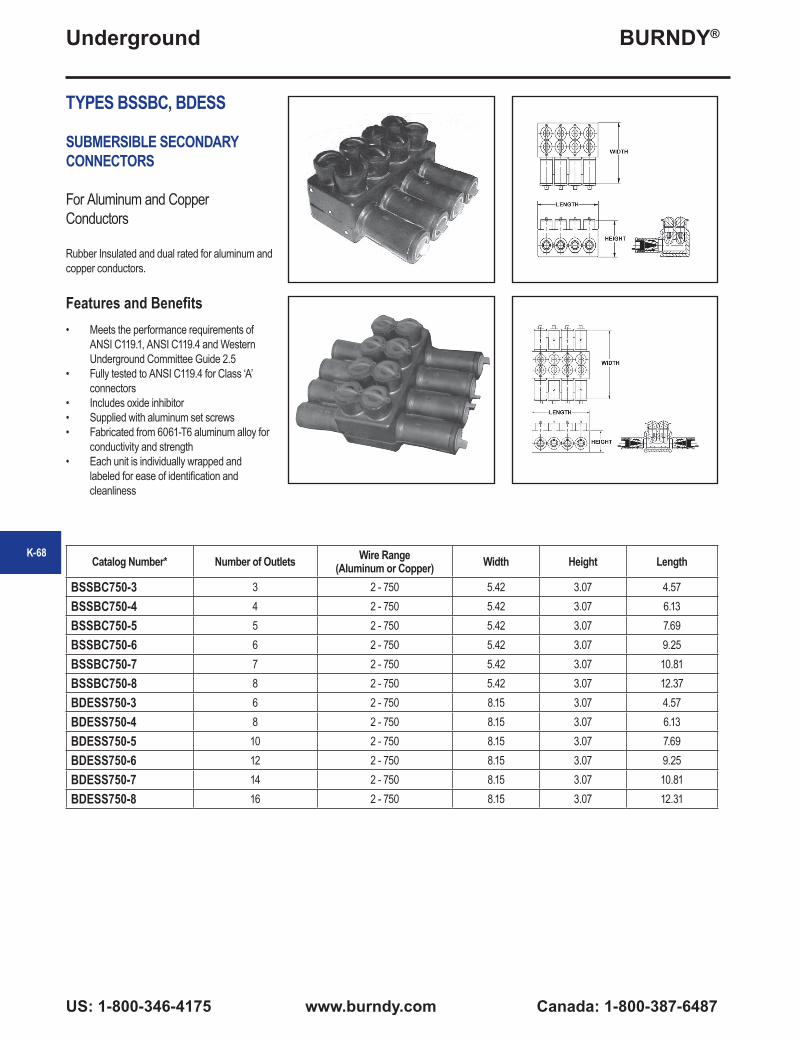
BURNDY®
US: 1-800-346-4175 www.burndy.com Canada: 1-800-387-6487
Underground
TYPES BSSBC, BDESS
SUBMERSIBLE SECONDARY CONNECTORS
For Aluminum and Copper Conductors
Rubber Insulated and dual rated for aluminum and copper conductors.
Features and Benefits• Meets the performance requirements of
ANSI C119.1, ANSI C119.4 and Western Underground Committee Guide 2.5
• Fully tested to ANSI C119.4 for Class ‘A’ connectors
• Includes oxide inhibitor• Supplied with aluminum set screws• Fabricated from 6061-T6 aluminum alloy for
conductivity and strength• Each unit is individually wrapped and
labeled for ease of identification and cleanliness
Catalog Number* Number of Outlets Wire Range (Aluminum or Copper) Width Height Length
BSSBC750-3 3 2 - 750 5.42 3.07 4.57BSSBC750-4 4 2 - 750 5.42 3.07 6.13BSSBC750-5 5 2 - 750 5.42 3.07 7.69BSSBC750-6 6 2 - 750 5.42 3.07 9.25BSSBC750-7 7 2 - 750 5.42 3.07 10.81BSSBC750-8 8 2 - 750 5.42 3.07 12.37BDESS750-3 6 2 - 750 8.15 3.07 4.57BDESS750-4 8 2 - 750 8.15 3.07 6.13BDESS750-5 10 2 - 750 8.15 3.07 7.69BDESS750-6 12 2 - 750 8.15 3.07 9.25BDESS750-7 14 2 - 750 8.15 3.07 10.81BDESS750-8 16 2 - 750 8.15 3.07 12.31
K-68
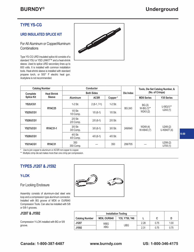
BURNDY®
Canada: 1-800-387-6487 www.burndy.com US: 1-800-346-4175
Underground
K-69
TYPE YS-CG
URD INSULATED SPLICE KIT
For All Aluminum or Copper/Aluminum Combinations
Type YS-CG URD insulated splice kit consists of a standard YSU or YSD LINKIT™ and a heat-shrink sleeve. Used to splice URD secondary lines up to 600 volts. It is installed with common installation tools. Heat-shrink sleeve is installed with standard propane torch, or 500° F electric heat gun. Acetylene is not recommended.
Catalog Number ConductorDie Index
Tools, Die Set Catalog Number, & (No. of Crimps)Complete
Splice KitHeat Shrink
SleeveBoth Sides
Aluminum ACSR Copper * MD6 Series Y35 Series
YS2UCG1RYAC25
1-2 Str. 2 (6-1, 7-1) 1-2 Str.BG 243
BG (3)W-BG (1)**W243 (2)
U-BG(1)**U243 (1)
YS25UCG1 1/0 Str.1/0 Comp. 1/0 (6-1) 1/0 Str.
YS26UCG1
RYAC31-1
2/0 Str.2/0 Comp. 2/0 (6-1) 2/0 Str.
249/840 W249 (4)W-K840 (7)
U249 (2)U-K840T (4)YS27UCG1 3/0 Str.
3/0 Comp. 3/0 (6-1) 3/0 Str.
YS28UCG1 4/0 Str.4/0 Comp. 4/0 (6-1) 4/0 Str.
YS31ACG1 RYAC31 350350 Comp. — 350 299/705 — U299 (2)
U705 (1)* Use to join copper to aluminum or ACSR not copper to copper.** Multiple crimp die set makes more than one crimp per compression.
TYPES J1207 & J1592
Y-LOK
For Locking Enclosure
Assembly consists of aluminum-clad steel wire loop and a compression type aluminum connector. Installed with BG groove of MD6 or OUR840 Compression Tools. Can also be installed with 5/8 or 5/8-1 grooves.
Catalog NumberInstallation Tooling
L C DMD6, OUR840 Y35, Y750, Y46J1207 WBG
XBG UBG2.28 0.75 1.00
J1592 2.31 0.75 0.75
J1207 & J1592
Compression Y-LOK installed with BG or 5/8 groove.

BURNDY®
US: 1-800-346-4175 www.burndy.com Canada: 1-800-387-6487
Underground
TYPE YRB-U
HYREDUCER™ SPLICE
For Aluminum to Aluminum and Aluminum to Copper
Type YRB-U splice is designed for use within underground systems. Aluminum splices are tin-plated and recommended for use on Aluminum-to-Aluminum and Aluminum-to-Copper cables. All
Catalog Number
Conductor Range DimensionsO.D.
Wire Strip Length Die
IndexColor CodeBarrel “A”
Copper & AluminumBarrel “B”
Copper & AluminumB
Min. L Barrel “A”
Barrel “B”
YRB2U3TTN #2 (.292 Dia.) 7 Str. #3 (.260 Dia.) 7 Str.
1.35[34]
3.25[83]
0.65[17] 1-3/4" 1-3/4" 296 Tan
YRB1CU2TTN #1 (.332 Dia.) 19 Str. or 1/0 Compact (.336 Dia.) 19 Str. #2 (.292 Dia.) 7 Str.
YRB1CU1TTN #1 (.332 Dia.) 19 Str. or 1/0 Compact (.336 Dia.) 19 Str.
#1 (.332 Dia.) 19 Str. or 1/0 Compact (.336 Dia.) 19 Str.
YRB25U3TTN 1/0 (.373 Dia.) 19 Str. or 1/0 Compact (.336 Dia.) 19 Str. #3 (.260 Dia.) 7 Str.
YRB25U2TTN 1/0 (.373 Dia.) 19 Str. or 1/0 Compact (.336 Dia.) 19 Str. #2 (.292 Dia.) 7 Str.
YRB25U25TTN 1/0 (.373 Dia.) 19 Str. or 1/0 Compact (.336 Dia.) 19 Str.
1/0 (.373 Dia.) 19 Str. or 1/0 Compact (.336 Dia.) 19 Str.
YRB27U25TW 3/0 (.470 Dia.) 19 Str. or 3/0 Compact (.423 Dia.) 19 Str.
1/0 (.373 Dia.) 19 Str. or 1/0 Compact (.336 Dia.) 19 Str.
1.53[39]
3.69[94]
0.85[22] 1-1/2" 1-1/2" 298 White
YRB28U3TW 4/0 (.528 Dia.) 19 Str. or 4/0 Compact (.475 Dia.) 19 Str. #3 (.260 Dia.) 7 Str.
YRB28U1TW 4/0 (.528 Dia.) 19 Str. or 4/0 Compact (.475 Dia.) 19 Str.
#1 (.332 Dia.) 19 Str. or 1/0 Compact (.336 Dia.) 19 Str.
YRB28U25TW 4/0 (.528 Dia.) 19 Str. or 4/0 Compact (.475 Dia.) 19 Str.
1/0 (.373 Dia.) 19 Str. or 1/0 Compact (.336 Dia.) 19 Str.
1.53[39]
3.70[94]
YRB28U26TW 4/0 (.528 Dia.) 19 Str. or 4/0 Compact (.475 Dia.) 19 Str.
2/0 (.419 Dia.) 19 Str. or 2/0 Compact (.376 Dia.) 19 Str. 1.53
[39]3.69[94]
YRB28U28TW 4/0 (.528 Dia.) 19 Str. or 4/0 Compact (.475 Dia.) 19 Str.
4/0 (.528 Dia.) 19 Str. or 4/0 Compact (.475 Dia.) 19 Str.
YRB31U25TW350 kcmil (.681 Dia.) 37 Str. or 350 kcmil
Compact (.616 Dia.) 19 Str. Al; 37 Str. Al & Cu
1/0 (.373 Dia.) 19 Str. or 1/0 Compact (.336 Dia.) 19 Str.
2.34[59]
5.43[138]
1.11[28] 2-1/4" 2-1/4" 299 BrownYRB31U28TW
350 kcmil (.681 Dia.) 37 Str. or 350 kcmil Compact (.616 Dia.) 19 Str. Al; 37 Str.
Al & Cu4/0 (.528 Dia.) 19 Str. or
250 kcmil Compact (.520 Dia.) 37 Str.
YRB31U31TW350 kcmil (.681 Dia.) 37 Str. or 350 kcmil
Compact (.616 Dia.) 19 Str. Al; 37 Str. Al & Cu
350 kcmil (.681 Dia.) 37 Str. or 350 kcmil Compact (.616 Dia.) 19 Str. Al;
37 Str. Al & Cu
splices have solid center stop for use with oil filled and non-oil filled cables. The Outside Diameter is held constant to minimize installation dies and
1 Material: Aluminum.2 Finish: Electro-tin plated. Barrels are partially filled with PENETROX™ and sealed.4 Scratch brushing of all conductors before making installation is recommended.5 Not for use with Copper-to-Copper applications.6 Dimensions in brackets [ ] are in millimeters rounded off to the nearest millimeter, unless otherwise noted and are for reference only.
3
Catalog number PT6515 Adaptor is required to use “U” dies in Y45 series tools. Catalog number PUADP-1 Adaptor is required to use “U” dies in Y46 series tools.9 On MY29-3 HYTOOL™ use alum. Index plate settings as follows, for 1/0 conductor use 1/0 setting. For conductor smaller than 1/0 size use 2/0 setting.
78
connectors are prefilled with PENETROX™. Rated up to 35 kV.
K-70

BURNDY®
Canada: 1-800-387-6487 www.burndy.com US: 1-800-346-4175
Underground
K-71
TYPE YRB-U
HYREDUCER™ SPLICE(Continued)
For Aluminum to Aluminum and Aluminum to Copper
Catalog Number
Conductor Range DimensionsO.D.
Wire Strip LengthDie
NumberColor CodeB Min. L Barrel
“A”Barrel
“B”Barrel “A”
Copper & AluminumBarrel “B”
Copper & Aluminum
YRB34U25TW500 kcmil (.813 Dia.) 37 Str. or 500 kcmil Compact (.736 Dia.)
19 Str. Al; 37 Str. Al & Cu1/0 (.373 Dia.) 19 Str.
2.70[69]
6.00[152]
1.31[33] 1-1/8" 1-1/8" 300 Pink
YRB34U28TW500 kcmil (.813 Dia.) 37 Str. or 500 kcmil Compact (.736 Dia.)
19 Str. Al; 37 Str. Al & Cu4/0 (.528 Dia.) 19 Str. or
4/0 Compact (.475 Dia.) 19 Str.
YRB34U29TW500 kcmil (.813 Dia.) 37 Str. or 500 kcmil Compact (.736 Dia.)
19 Str. Al; 37 Str. Al & Cu250 kcmil (.575 Dia.) 37 Str.
YRB34U30TW500 kcmil (.813 Dia.) 37 Str. or 500 kcmil Compact (.736 Dia.)
19 Str. Al; 37 Str. Al & Cu300 kcmil (.630 Dia) 37 Str.
YRB34U31TW500 kcmil (.813 Dia.) 37 Str. or 500 kcmil Compact (.736 Dia.)
19 Str. Al; 37 Str. Al & Cu
350 kcmil (.681 Dia.) 37 Str. or 350 kcmil Compact (.616 Dia.) 19
Str. Al; 37 Str. Al & Cu
YRB34U34TW500 kcmil (.813 Dia.) 37 Str. or 500 kcmil Compact (.736 Dia.)
19 Str. Al; 37 Str. Al & Cu
500 kcmil (.813 Dia.) 37 Str. or 500 kcmil Compact (.736 Dia.) 19
Str. Al; 37 Str. Al & Cu
YRB39U31TW700 kcmil (.964 Dia.) 61 Str.,
750 kcmil (.998 Dia.) 61 Str. or 750 kcmil Compact (.908 Dia.)
61 Str.
350 kcmil (.681 Dia.) 37 Str. or 350 kcmil Compact (.616 Dia.) 19
Str. Al; 37 Str. Al & Cu
2.87[73]
6.74[171]
1.46[37] 3" 3-11/16" 936 Yellow
YRB39U34TW700 kcmil (.964 Dia.) 61 Str.,
750 kcmil (.998 Dia.) 61 Str. or 750 kcmil Compact (.908 Dia.)
61 Str.
500 kcmil (.813 Dia.) 37 Str. or 500 kcmil Compact (.736 Dia.) 19
Str. Al; 37 Str. Al & Cu
YRB39U39TW700 kcmil (.964 Dia.) 61 Str.,
750 kcmil (.998 Dia.) 61 Str. or 750 kcmil Compact (.908 Dia.)
61 Str.
700 kcmil (.964 Dia.) 61 Str.,750 kcmil (.998 Dia.) 61 Str. or 750 kcmil Compact (.908 Dia.)
61 Str.
YRB44U31TW 1000 kcmil (1.152 Dia.) 61 Str.350 kcmil (.681 Dia.) 37 Str. or
350 kcmil Compact (.616 Dia.) 19 Str. Al; 37 Str. Al & Cu
YRB44U34TW 1000 kcmil (1.152 Dia.) 61 Str.500 kcmil (.813 Dia.) 37 Str. or
500 kcmil Compact (.736 Dia.) 19 Str. Al; 37 Str. Al & Cu
YRB44U39TW 1000 kcmil (1.152 Dia.) 61 Str.700 kcmil (.964 Dia.) 61 Str.,
750 kcmil (.998 Dia.) 61 Str. or 750 kcmil Compact (.908 Dia.)
61 Str.
YRB44U44TW 1000 kcmil (1.152 Dia.) 61 Str. 1000 kcmil (1.152 Dia.) 61 Str.
1 Material: Aluminum.2 Finish: Electro-tin plated. Barrels are partially filled with PENETROX™ and sealed.4 Scratch brushing of all conductors before making installation is recommended.5 Not for use with Copper-to-Copper applications.6 Dimensions in brackets [ ] are in millimeters rounded off to the nearest millimeter, unless otherwise noted and are for reference only.
Catalog number PT6515 Adaptor is required to use “U” dies in Y45 series tools.Catalog number PUADP-1 Adaptor is required to use “U” dies in Y46 series tools.9 On MY29-3 HYTOOL™ use alum. Index plate settings as follows, for 1/0 conductor use 1/0 setting. For conductor smaller than 1/0 size use 2/0 setting.

BURNDY®
US: 1-800-346-4175 www.burndy.com Canada: 1-800-387-6487
Underground
TYPE YRB-U
HYREDUCER™ SPLICE(Continued)
For Aluminum to Aluminum and Aluminum to Copper
Installation (Number of Crimps per End)
Color Code Die Index
Hydraulic Dieless (# of Crimps)
Y35, Y39, Y750, BAT35, BAT750,
PAT750Y46 Y45 Y60-
Mechanical: MY29-3 (1),MY29011 (1)Hydraulic:Y644M (1),
PAT644-18V (1)
Tan 296 U25ART (1) U25ART (1) U25ART (1) — MY29-3 (1)MY29-11 (1)Y644M (1)
PAT644-18V (1)White 298 U28ART (2) U28ART (2) U28ART (2) —
Brown 299 U31ARTOverlap Crimp
U31ARTOverlap Crimp
U31ARTOverlap Crimp L31ART (1)
Y644M (1)PAT644-18V (1)
Pink 300 U34ARTOverlap Clamp
U34ARTOverlap Clamp
U34ARTOverlap Clamp L34ART
Yellow 936 U39ART-2 (4) U39ART-2 (4) U39ART-2 (4) L39ART (2) —
K-72
1 Material: Aluminum.2 Finish: Electro-tin plated. Barrels are partially filled with PENETROX™ and sealed.4 Scratch brushing of all conductors before making installation is recommended.5 Not for use with Copper-to-Copper applications.6 Dimensions in brackets [ ] are in millimeters rounded off to the nearest millimeter, unless otherwise noted and are for reference only.
Catalog number PT6515 Adaptor is required to use “U” dies in Y45 series tools.Catalog number PUADP-1 Adaptor is required to use “U” dies in Y46 series tools.9 On MY29-3 HYTOOL™ use alum. Index plate settings as follows, for 1/0 conductor use 1/0 setting. For conductor smaller than 1/0 size use 2/0 setting.

BURNDY®
Canada: 1-800-387-6487 www.burndy.com US: 1-800-346-4175
Underground
K-73
TYPE YRB-T
HYREDUCER™ SPLICE
For Copper to Copper
Type YRB-T splice is designed for use within underground systems. Copper splices are tapered and recommended for use on copper-to-copper cables.
All splices have solid center stops for use with oil filled and non-oil filled cables.
The Outside Diameter is held constant to minimize installation dies. Rated up to 35 kV
Catalog Number
Figure No.
Conductor Size DimensionsBarrel “A” Barrel “B” B Min. BB Min. L O.D.
YRB2825T 2 4/0 (0.53) 1/0 (0.37) 1.16[29]
1.16[29]
2.84[73]
0.69[18]
YRB3428T 3 500 kcmil 4/0 (0.53) 1.73[44]
1.73[44]
4.50[114]
1.06[27]
Catalog Number
Color Code
Installation Tooling (Number of Crimps)
Dieless (# of Crimps)
Wire Strip
Length
Die Information Mechanical Hydraulic
Die Index Type OUR840 MD7
MD7-34R MD6Y35, Y39,
Y750, PAT750
BCT500, Y500CT Y46 Y45 Y60-
YRB2825T Purple Die 15 Purple Die Set
X28VT (4)
X28RT (4)
X28VT (4) X28VT (4) U28RT (1) — U28RT
(1) — L29ART (1)Hydraulic:Y644M (1)
PAT644M (1)1-7/32"
YRB3428T BrownDie
20 or 299
Brown Die Set — — —
U34ART (2)
U31ART (2)
W34VT (2)
W34RT (2)
U34RT (2)
U31ART (2)
U34RT (2)
U31ART (2)
L34RT (1)Hydraulic:Y644M (1)
PAT644M (1)1-13/16"
1 Material: Copper. For Tin-Plating, add suffix “TN” to the Catalog Number (example: YRB2825TN). For Hot Tin dipped add suffix “W” to the catalog number (example: YRB2825TW). Catalog Number PT6515 Adaptor is required to use “U” dies in Y45 series tools. Catalog Number PUADP-1 is required to use “U” dies in Y46 series tools.
5 Dimensions in brackets [ ] are in millimeters rounded off to the nearest millimeter, unless otherwise specified, and are for reference only. Suffix “TN” and “W” will not be stamped on part.
2
2
2
3
3
4
4
7
7
7
Fig. 1
Fig. 3Fig. 2

BURNDY®
US: 1-800-346-4175 www.burndy.com Canada: 1-800-387-6487
Underground
TYPES BSSI, BTWTC
SUBMERSIBLE SPLICE COVERS
Soft Rubber Covers for Insulating
Features and Benefits• 600 Volt compression splice connections
including those subject to water submersion: Suitable for direct burial. Ends have stepped sealing surfaces to accommodate a wide variety of conductor sizes
• Maintains watertight integrity and full insulating value in all direct buried, underground networks, residential and overhead service joints
• Taping is eliminated and splice preparation is significantly reduced
• Meets the performance requirements of ANSI C119.1, ANSI C119.4 and Western Underground Committee Guide 2.5
Catalog Number
Copper Conductor
AluminumConductor
CableInsulation
BodyLength
BodyDiameter
Uncompressed Splice Size
O.D. O.A.L.
BSSI-20 14 - 2/0 14 - 2/0 0.15 - 0.60 4.40 0.84 0.75 3.00
BSSI-500 14 - 500 14 - 500 0.15 - 1.18 5.30 1.25 1.19 4.00
BSSI-500L 14 - 500 14 - 500 0.15 - 1.18 7.70 1.35 1.19 6.00
Catalog Number
Cable Range BodyLengthD E F
BTWTC500 14 - 500 14 - 250 14 - 250 5.30
NOTE: Covers are supplied without connectors.
K-74
BTWTC500
BSSI style
D E
F

BURNDY®
Canada: 1-800-387-6487 www.burndy.com US: 1-800-346-4175
Underground
K-75
TYPE K-P-C
URD
URD Service Tap forCopper Conductors
These compact, wide-range-taking, multiple outlet connectors are made of high conductivity copper alloy. Spherical point Allen set screws provide even clamping forces on conductors up to 4/0 Str. Each connector is supplied with an insulating cover. The mechanical clamping elements allow individual cables to be disconnected without disturbing adjacent connections.
Catalog NumberConductor Number
of Outlets A B CComplete Assembly
Connector Only
Cover Only
K6P28C K6P28 K-PC28 6 Str - 4/0 Str. 6 5-1/8 2-3/4 1-5/8
COMPRESSION SERVICE TAPS AND TRANSFORMER TERMINALS
Where compression-type service taps are required, the wide-range-taking, figure “6” shaped, tap connectors are recommended. They can be gripped in a HYPRESS™ and slipped over the secondary main for easy installation. For above-grade installation, commercially available insulating tubes are often used to cover a series of these taps on each main cable stub. Separation of run and tap cables simplifies taping.
TYPE YPC-C
TIN-PLATEDCOPPER CRIMPIT™
For Copper Conductors
Made of tin-plated pure copper this connector is recommended for copper service taps in above-grade enclosures or for direct burial. The streamlined design facilitates taping. The plating eliminates reaction with insulators.
Catalog Number
ConductorL Die
Index
Installation Tooling
Run TapY35, Y750, Y46* HYPRESS™
Die Cat. No. (No. of Crimps)YPC29C26 2/0 Str.-250 4 Str.-2/0 Str. 1.00 D3 U-D3 (1)
* Y46 requires PUADP-1 adapter to use U-dies.
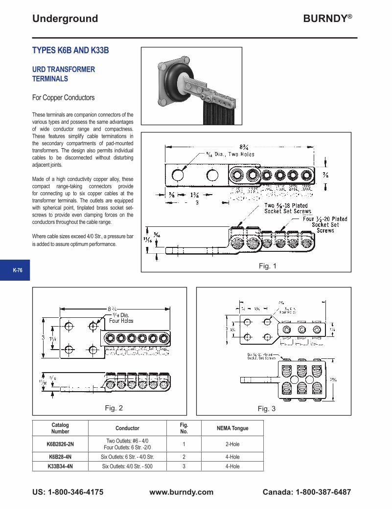
BURNDY®
US: 1-800-346-4175 www.burndy.com Canada: 1-800-387-6487
Underground
TYPES K6B AND K33B
URD TRANSFORMERTERMINALS
For Copper Conductors
These terminals are companion connectors of the various types and possess the same advantages of wide conductor range and compactness. These features simplify cable terminations in the secondary compartments of pad-mounted transformers. The design also permits individual cables to be disconnected without disturbing adjacent joints.
Made of a high conductivity copper alloy, these compact range-taking connectors provide for connecting up to six copper cables at the transformer terminals. The outlets are equipped with spherical point, tinplated brass socket set-screws to provide even clamping forces on the conductors throughout the cable range.
Where cable sizes exceed 4/0 Str., a pressure bar is added to assure optimum performance.
Catalog Number Conductor Fig.
No. NEMA Tongue
K6B2826-2N Two Outlets: #6 - 4/0Four Outlets: 6 Str. -2/0 1 2-Hole
K6B28-4N Six Outlets: 6 Str. - 4/0 Str. 2 4-HoleK33B34-4N Six Outlets: 4/0 Str. - 500 3 4-Hole
Fig. 1
Fig. 2 Fig. 3
K-76

BURNDY®
Canada: 1-800-387-6487 www.burndy.com US: 1-800-346-4175
Underground
K-77
TYPE F-A
URD FUSED TRANSFORMER TERMINALS
These Transformer Tap assembles bolt directly to the secondary terminal pad. They provide for up to eight cables to be fused directly at the secondary terminals. This may be all service taps or combinations of secondary mains and service taps. Catalog Number Number of Fuses L Inches
F22A28 4 6-1/2
Type LF Limiter and HYLUG™ (copper or aluminum). Compression terminals must be ordered separately.
TYPE K6A34U
TRANSFORMER TERMINALS
For Aluminum and Copper Conductors
Made of aluminum alloy, the massive design minimizes conductor corrosion due to galvanic action. Each outlet is pre-filled with PENETROX™ joint compound and sealed. Plated aluminum socket head pressure screws and aluminum pressure bars prevent conductor damage. Six hole pad allows for adjustable positioning on four hole NEMA spades.
Catalog Number Conductor Number of Outlets
K6A34U-6N Two Outlets 2 Str.-500Four Outlets 6 Str.-4/0 Str. 6
TYPE K-P-UC
UNIVERSAL URD SERVICE TAP
For Aluminum or Copper
Made of aluminum alloy, the massive design minimizes conductor corrosion due to galvanic action. Each outlet is pre-filled with PENETROX™ joint compound and sealed. Plated aluminum socket head pressure screws and aluminum pressure bars prevent conductor damage. Each connector is supplied with an insulating cover.
Catalog NumberConductor Number of
Outlets A B CComplete Assembly
Connector Only
Cover Only
K6P34UC K6P34U K6PC34UTwo Outlets 2 Str. - 500
Four Outlets 6 Str.- 4/0 Str.
6 5-3/4 3-1/8 2-1/8

BURNDY®
US: 1-800-346-4175 www.burndy.com Canada: 1-800-387-6487
Underground
TYPES BPD & BPD2
POWER DISTRIBUTIONBLOCKS
Dual rated ground pedestal lugs. Rated for 600 volt. Constructed from high strength aluminum alloy 6061-T6. Connectors are all plated to provide low contact resistance.
Plastisol covers dielectric strength rating of 120 volts per mil. Nominal thickness is 156 mils. Covers purchased separately.
Catalog Number
Wire Range Aluminum or Copper
Number of Conductors
DimensionsInsulating Cover
A B C
BPD-4-350 #6-350 4 3.88 1.38 1.00 BIC-4-350
BPD-6-350 #6-350 6 5.69 1.38 1.00 BIC-6-350
BPD-8-350 #6-350 8 7.50 1.38 1.00 BIC-8-350
BPD-4-500 #2-500 4 4.75 1.63 1.00 BIC-4-500
BPD-6-500 #2-500 6 7.00 1.63 1.00 BIC-6-500
BPD-8-500 #2-500 8 9.25 1.63 1.00 BIC-8-500
BPD2-4-750 #2-750 4 6.56 2.00 2.50 BIC2-4-750
BPD2-6-750 #2-750 6 9.88 2.00 2.50 BIC2-6-750
BPD2-8-750 #2-750 8 13.81 2.00 2.50 BIC2-8-750
BPD
BPD2
BIC
BIC2
K-78