Organic photovoltaics: Crosslinking for optimal … Today Volume 18,Number 8 October 2015 RESEARCH...
11
Materials Today Volume 18, Number 8 October 2015 RESEARCH Organic photovoltaics: Crosslinking for optimal morphology and stability Joseph W. Rumer 1, * and Iain McCulloch 1,2 1 Department of Chemistry and Centre for Plastic Electronics, Imperial College London, London SW7 2AZ, UK 2 Physical Sciences and Engineering Division and SPERC, King Abdullah University of Science and Technology (KAUST), Thuwal 23955-6900, Saudi Arabia Organic solar cells now exceed 10% efficiency igniting interest not only in the fundamental molecular design of the photoactive semiconducting materials, but also in overlapping fields such as green chemistry, large-scale processing and thin film stability. For these devices to be commercially useful, they must have lifetimes in excess of 10 years. One source of potential instability, is that the two bicontinuous phases of electron donor and acceptor materials in the photoactive thin film bulk heterojunction, change in dimensions over time. Photocrosslinking of the p-conjugated semiconducting donor polymers allows the thin film morphology to be ‘locked’ affording patterned and stable blends with suppressed fullerene acceptor crystallization. This article reviews the performance of crosslinkable polymers, fullerenes and additives used to-date, identifying the most promising. Introduction Since the award of a Nobel Prize in Chemistry in 2000 for ‘‘the discovery and development of conductive polymers’’ [1] organic elec- tronic materials are emerging in applications such as mobile phone displays and niche products such as laptop bags with built-in solar powered chargers [2]. Additional potential applica- tions include solid-state lighting, thermoelectrics and lasers, with prospective applications in textiles, construction and health care [3]. For example, BASF have recently developed a concept car with Daimler, incorporating a transparent organic solar cell in the roof [4]. The potential of organic electronics rests not in their inher- ently inexpensive composition – being based largely on the earth’s most abundant elements: carbon, nitrogen and oxygen – but rather in their amenability to solution processed manufacturing methods, such as ink-jet and roll-to-roll (R2R) printing [5–7]. Inherent to R2R printing is flexibility, light-weight and large-scale compatibility. This makes for a contrast to rigid, more fragile and inherently small-area, batch-produced, inorgan- ic solar cells, cut from crystalline silicon [2]. Coupled with a shortage of fossil fuels and rising carbon dioxide levels, a growing global energy demand makes solar an underexploited renewable energy source. Organic solar cell devices are an emerging class of photovoltaics, but have up until this point been unable to both overcome up-scaling challenges and find an appropriate market entry application. However, the superior performance of organic solar cell devices to inorganics such as silicon for indoor applica- tions, coupled with the need for ubiquitous low energy indoor wireless transmission devices, offers a genuinely unique oppor- tunity for organic photovoltaics as a light harvesting product and it is essential to ensure that this product offering is robust and comprehensive. It is often cited that successful commercializa- tion of solution deposited organic solar cells will rely on the combination of performance, lifetime and cost simultaneously achieving appropriate values. A target of 10% power conversion efficiency (PCE) is generally accepted for organic solar modules, or photovoltaic (OPV) devices, to become commercially viable [8], which has now been surpassed at the research level [9–11]. The new challenge for the OPV community is to deliver high perfor- mance combined with sufficient long-term stability, with a gen- erally accepted target being a lifetime of 10 years [12,13]. Whilst it is a simple task to track performance increases in the field, improvements in both lifetime and cost are less easy to measure or track. Much more effort will be focused on these parameters as development and production commences. Avoidance of low yielding, complicated and multi-step synthesis with expensive RESEARCH: Review *Corresponding author. Rumer, J.W. ([email protected]), McCulloch, I. ([email protected]) 1369-7021/ß 2015 The Authors. Published by Elsevier Ltd. This is an open access article under the CC BY-NC-ND license (http://creativecommons.org/licenses/by-nc-nd/4.0/). http://dx.doi.org/10.1016/ j.mattod.2015.04.001 425
-
Upload
truongthuy -
Category
Documents
-
view
224 -
download
0
Transcript of Organic photovoltaics: Crosslinking for optimal … Today Volume 18,Number 8 October 2015 RESEARCH...
RESEARCH:Review
Materials Today � Volume 18, Number 8 �October 2015 RESEARCH
Organic photovoltaics: Crosslinking foroptimal morphology and stabilityJoseph W. Rumer1,* and Iain McCulloch1,2
1Department of Chemistry and Centre for Plastic Electronics, Imperial College London, London SW7 2AZ, UK2 Physical Sciences and Engineering Division and SPERC, King Abdullah University of Science and Technology (KAUST), Thuwal 23955-6900, Saudi Arabia
Organic solar cells now exceed 10% efficiency igniting interest not only in the fundamental molecular
design of the photoactive semiconducting materials, but also in overlapping fields such as green
chemistry, large-scale processing and thin film stability. For these devices to be commercially useful,
they must have lifetimes in excess of 10 years. One source of potential instability, is that the two
bicontinuous phases of electron donor and acceptor materials in the photoactive thin film bulk
heterojunction, change in dimensions over time. Photocrosslinking of the p-conjugated semiconducting
donor polymers allows the thin film morphology to be ‘locked’ affording patterned and stable blends
with suppressed fullerene acceptor crystallization. This article reviews the performance of crosslinkable
polymers, fullerenes and additives used to-date, identifying the most promising.
IntroductionSince the award of a Nobel Prize in Chemistry in 2000 for ‘‘the
discovery and development of conductive polymers’’ [1] organic elec-
tronic materials are emerging in applications such as mobile
phone displays and niche products such as laptop bags with
built-in solar powered chargers [2]. Additional potential applica-
tions include solid-state lighting, thermoelectrics and lasers, with
prospective applications in textiles, construction and health care
[3]. For example, BASF have recently developed a concept car with
Daimler, incorporating a transparent organic solar cell in the roof
[4]. The potential of organic electronics rests not in their inher-
ently inexpensive composition – being based largely on the
earth’s most abundant elements: carbon, nitrogen and oxygen
– but rather in their amenability to solution processed
manufacturing methods, such as ink-jet and roll-to-roll (R2R)
printing [5–7]. Inherent to R2R printing is flexibility, light-weight
and large-scale compatibility. This makes for a contrast to rigid,
more fragile and inherently small-area, batch-produced, inorgan-
ic solar cells, cut from crystalline silicon [2]. Coupled with a
shortage of fossil fuels and rising carbon dioxide levels, a growing
global energy demand makes solar an underexploited renewable
*Corresponding author. Rumer, J.W. ([email protected]),
McCulloch, I. ([email protected])
1369-7021/� 2015 The Authors. Published by Elsevier Ltd. This is an open access article under the CC BY-N
j.mattod.2015.04.001
energy source. Organic solar cell devices are an emerging class of
photovoltaics, but have up until this point been unable to both
overcome up-scaling challenges and find an appropriate market
entry application. However, the superior performance of organic
solar cell devices to inorganics such as silicon for indoor applica-
tions, coupled with the need for ubiquitous low energy indoor
wireless transmission devices, offers a genuinely unique oppor-
tunity for organic photovoltaics as a light harvesting product and
it is essential to ensure that this product offering is robust and
comprehensive. It is often cited that successful commercializa-
tion of solution deposited organic solar cells will rely on the
combination of performance, lifetime and cost simultaneously
achieving appropriate values. A target of 10% power conversion
efficiency (PCE) is generally accepted for organic solar modules, or
photovoltaic (OPV) devices, to become commercially viable [8],
which has now been surpassed at the research level [9–11]. The
new challenge for the OPV community is to deliver high perfor-
mance combined with sufficient long-term stability, with a gen-
erally accepted target being a lifetime of 10 years [12,13]. Whilst it
is a simple task to track performance increases in the field,
improvements in both lifetime and cost are less easy to measure
or track. Much more effort will be focused on these parameters as
development and production commences. Avoidance of low
yielding, complicated and multi-step synthesis with expensive
C-ND license (http://creativecommons.org/licenses/by-nc-nd/4.0/). http://dx.doi.org/10.1016/
425
RESEARCH Materials Today �Volume 18, Number 8 �October 2015
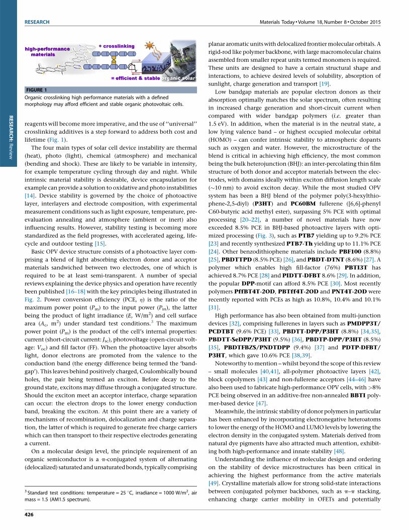
FIGURE 1
Organic crosslinking high performance materials with a defined
morphology may afford efficient and stable organic photovoltaic cells.
RESEARCH:Review
reagents will become more imperative, and the use of ‘‘universal’’
crosslinking additives is a step forward to address both cost and
lifetime (Fig. 1).
The four main types of solar cell device instability are thermal
(heat), photo (light), chemical (atmosphere) and mechanical
(bending and shock). These are likely to be variable in intensity,
for example temperature cycling through day and night. While
intrinsic material stability is desirable, device encapsulation for
example can provide a solution to oxidative and photo instabilities
[14]. Device stability is governed by the choice of photoactive
layer, interlayers and electrode composition, with experimental
measurement conditions such as light exposure, temperature, pre-
evaluation annealing and atmosphere (ambient or inert) also
influencing results. However, stability testing is becoming more
standardized as the field progresses, with accelerated ageing, life-
cycle and outdoor testing [15].
Basic OPV device structure consists of a photoactive layer com-
prising a blend of light absorbing electron donor and acceptor
materials sandwiched between two electrodes, one of which is
required to be at least semi-transparent. A number of special
reviews explaining the device physics and operation have recently
been published [16–18] with the key principles being illustrated in
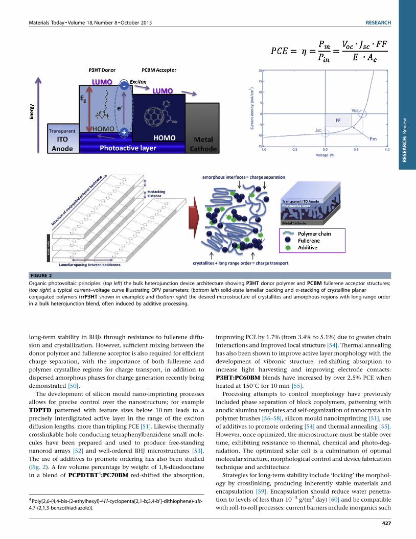
Fig. 2. Power conversion efficiency (PCE, h) is the ratio of the
maximum power point (Pm) to the input power (Pin), the latter
being the product of light irradiance (E, W/m2) and cell surface
area (Ac, m2) under standard test conditions.3 The maximum
power point (Pm) is the product of the cell’s internal properties:
current (short-circuit current: Jsc), photovoltage (open-circuit volt-
age: Voc) and fill factor (FF). When the photoactive layer absorbs
light, donor electrons are promoted from the valence to the
conduction band (the energy difference being termed the ‘band-
gap’). This leaves behind positively charged, Coulombically bound
holes, the pair being termed an exciton. Before decay to the
ground state, excitons may diffuse through a conjugated structure.
Should the exciton meet an acceptor interface, charge separation
can occur: the electron drops to the lower energy conduction
band, breaking the exciton. At this point there are a variety of
mechanisms of recombination, delocalization and charge separa-
tion, the latter of which is required to generate free charge carriers
which can then transport to their respective electrodes generating
a current.
On a molecular design level, the principle requirement of an
organic semiconductor is a p-conjugated system of alternating
(delocalized) saturated and unsaturated bonds, typically comprising
3 Standard test conditions: temperature = 25 8C, irradiance = 1000 W/m2, airmass = 1.5 (AM1.5 spectrum).
426
planar aromatic units with delocalized frontier molecular orbitals. A
rigid-rod like polymer backbone, with large macromolecular chains
assembled from smaller repeat units termed monomers is required.
These units are designed to have a certain structural shape and
interactions, to achieve desired levels of solubility, absorption of
sunlight, charge generation and transport [19].
Low bandgap materials are popular electron donors as their
absorption optimally matches the solar spectrum, often resulting
in increased charge generation and short-circuit current when
compared with wider bandgap polymers (i.e. greater than
1.5 eV). In addition, when the material is in the neutral state, a
low lying valence band – or highest occupied molecular orbital
(HOMO) – can confer intrinsic stability to atmospheric dopants
such as oxygen and water. However, the microstructure of the
blend is critical in achieving high efficiency, the most common
being the bulk heterojunction (BHJ): an inter-percolating thin film
structure of both donor and acceptor materials between the elec-
trodes, with domains ideally within exciton diffusion length scale
(�10 nm) to avoid exciton decay. While the most studied OPV
system has been a BHJ blend of the polymer poly(3-hexylthio-
phene-2,5-diyl) (P3HT) and PC60BM fullerene ([6,6]-phenyl
C60-butyric acid methyl ester), surpassing 5% PCE with optimal
processing [20–22], a number of novel materials have now
exceeded 8.5% PCE in BHJ-based photoactive layers with opti-
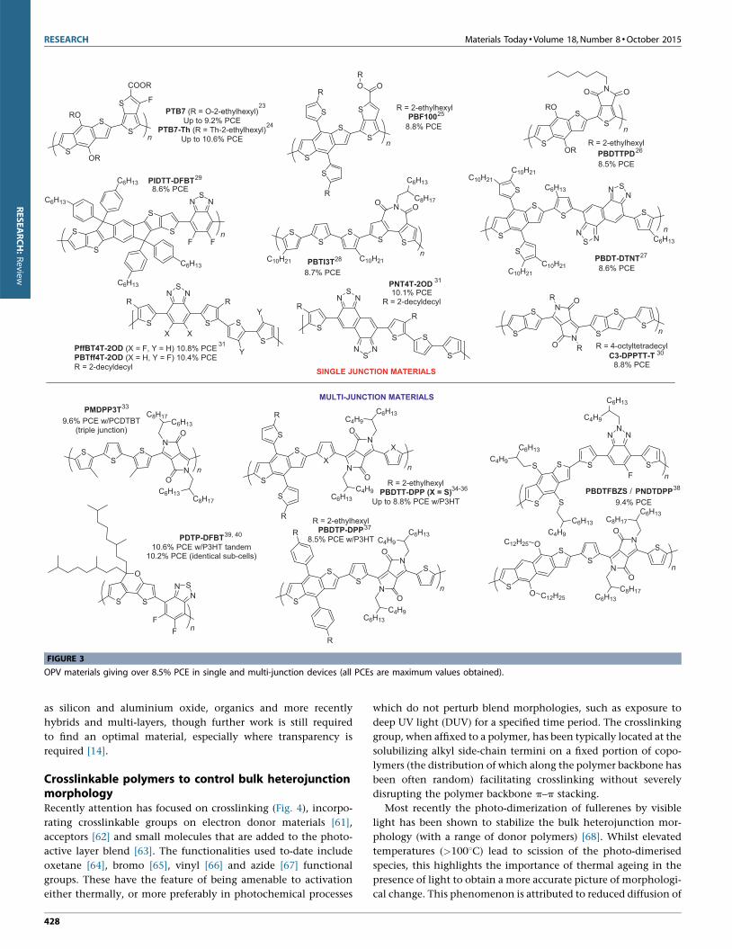
mized processing (Fig. 3), such as PTB7 yielding up to 9.2% PCE
[23] and recently synthesized PTB7-Th yielding up to 11.1% PCE
[24]. Other benzodithiophene materials include PBF100 (8.8%)
[25], PBDTTPD (8.5% PCE) [26], and PBDT-DTNT (8.6%) [27]. A
polymer which enables high fill-factor (76%) PBTI3T has
achieved 8.7% PCE [28] and PIDTT-DFBT 8.6% [29]. In addition,
the popular DPP-motif can afford 8.5% PCE [30]. Most recently
polymers PffBT4T-2OD, PBTff4T-2OD and PNT4T-2OD were
recently reported with PCEs as high as 10.8%, 10.4% and 10.1%
[31].
High performance has also been obtained from multi-junction
devices [32], comprising fullerenes in layers such as PMDPP3T/
PCDTBT (9.6% PCE) [33], PBDTT-DPP/P3HT (8.8%) [34,35],
PBDTT-SeDPP/P3HT (9.5%) [36], PBDTP-DPP/P3HT (8.5%)
[35], PBDTFBZS/PNDTDPP (9.4%) [37] and PDTP-DFBT/
P3HT, which gave 10.6% PCE [38,39].
Noteworthy to mention – whilst beyond the scope of this review
– small molecules [40,41], all-polymer photoactive layers [42],
block copolymers [43] and non-fullerene acceptors [44–46] have
also been used to fabricate high-performance OPV cells, with >8%
PCE being observed in an additive-free non-annealed BBTI poly-
mer-based device [47].
Meanwhile, the intrinsic stability of donor polymers in particular
has been enhanced by incorporating electronegative heteroatoms
to lower the energy of the HOMO and LUMO levels by lowering the
electron density in the conjugated system. Materials derived from
natural dye pigments have also attracted much attention, exhibit-
ing both high-performance and innate stability [48].
Understanding the influence of molecular design and ordering
on the stability of device microstructures has been critical in
achieving the highest performance from the active materials
[49]. Crystalline materials allow for strong solid-state interactions
between conjugated polymer backbones, such as p–p stacking,
enhancing charge carrier mobility in OFETs and potentially
Materials Today � Volume 18, Number 8 �October 2015 RESEARCH
FIGURE 2
Organic photovoltaic principles: (top left) the bulk heterojunction device architecture showing P3HT donor polymer and PCBM fullerene acceptor structures;(top right) a typical current–voltage curve illustrating OPV parameters; (bottom left) solid-state lamellar packing and p-stacking of crystalline planar
conjugated polymers (rrP3HT shown in example); and (bottom right) the desired microstructure of crystallites and amorphous regions with long-range order
in a bulk heterojunction blend, often induced by additive processing.
RESEARCH:Review
long-term stability in BHJs through resistance to fullerene diffu-
sion and crystallization. However, sufficient mixing between the
donor polymer and fullerene acceptor is also required for efficient
charge separation, with the importance of both fullerene and
polymer crystallite regions for charge transport, in addition to
dispersed amorphous phases for charge generation recently being
demonstrated [50].
The development of silicon mould nano-imprinting processes
allows for precise control over the nanostructure; for example
TDPTD patterned with feature sizes below 10 nm leads to a
precisely interdigitated active layer in the range of the exciton
diffusion lengths, more than tripling PCE [51]. Likewise thermally
crosslinkable hole conducting tetraphenylbenzidene small mole-
cules have been prepared and used to produce free-standing
nanorod arrays [52] and well-ordered BHJ microstructures [53].
The use of additives to promote ordering has also been studied
(Fig. 2). A few volume percentage by weight of 1,8-diiodooctane
in a blend of PCPDTBT4:PC70BM red-shifted the absorption,
4 Poly[2,6-(4,4-bis-(2-ethylhexyl)-4H-cyclopenta[2,1-b;3,4-b0]-dithiophene)-alt-4,7-(2,1,3-benzothiadiazole)].
improving PCE by 1.7% (from 3.4% to 5.1%) due to greater chain
interactions and improved local structure [54]. Thermal annealing
has also been shown to improve active layer morphology with the
development of vibronic structure, red-shifting absorption to
increase light harvesting and improving electrode contacts:
P3HT:PC60BM blends have increased by over 2.5% PCE when
heated at 1508C for 10 min [55].
Processing attempts to control morphology have previously
included phase separation of block copolymers, patterning with
anodic alumina templates and self-organization of nanocrystals in
polymer brushes [56–58], silicon mould nanoimprinting [51], use
of additives to promote ordering [54] and thermal annealing [55].
However, once optimized, the microstructure must be stable over
time, exhibiting resistance to thermal, chemical and photo-deg-
radation. The optimized solar cell is a culmination of optimal
molecular structure, morphological control and device fabrication
technique and architecture.
Strategies for long-term stability include ‘locking’ the morphol-
ogy by crosslinking, producing inherently stable materials and
encapsulation [59]. Encapsulation should reduce water penetra-
tion to levels of less than 10�3 g/(m2 day) [60] and be compatible
with roll-to-roll processes: current barriers include inorganics such
427
RESEARCH Materials Today �Volume 18, Number 8 �October 2015
PTB7 (R = O-2-eth ylhexyl)Up to 9.2% PCE
PTB7-Th (R = Th-2-eth ylhexyl)Up to 10.6% PCE
S
S
OR
RO
S
S F
COOR
nR = 2-eth ylhexy lS
S
OR
RO
S
N O
n
8.5% PCE
O
PBDTTPD
PBTI3T
SS
n
8.7% PCE
SS
C10 H21C10 H21
N
S
O OC8H17
C6H13
SINGLE JUNCTIO N MATERI ALS
MULTI-JUNCTIO N MATERI ALS
n
PMDPP3T
N
N
C8H17C6H13
C8H17C6H13O
O
SS
S
R = 2-eth ylhexy lPBDTT-DP P (X = S)
Up to 8.8 % PC E w/P3HT
S
SX
n
S
S
R
R
N
N
O
O
C6H13C4H9
X
S
S
S
Sn
S S
NN
N
PBDTFBZS
F
C4H9
C6H13
SO
SnN
N
O
O
C6H13C8H17
S
PNDTDPP
SO
C12 H25
C12 H25C8H17
C6H13
C4H9C6H13 9.4% PCE
/
9.6% PC E w/PCD TBT(triple junction)
C4H9
C6H13
C4H9
C6H13
S
SS
nN
N
O
O
S
R
R
R = 2-eth ylhexy lPBDTP-DPP
8.5% PC E w/P3HT C4H9C6H13
C4H9C6H13
10.6% PC E w/P3HT tandem10.2% PC E (identica l sub-cells)
S
O
S
FF
NSN
n
PDTP-DFBT
R = 2-eth ylhexy l
n
8.8% PCEPBF100
S
S
S
S
C6H13
C6H13
C6H13
C6H13
NS
N
F Fn
PIDTT-DFBT8.6% PCE
S
SS
S
S
R
R
S
O OR
n
8.6% PCEPBDT-DTNT
S
SS
S
S
C10 H21
C10 H21
C6H13
S
C6H13
C10 H21
C10 H21
NSN
NS N
2325
26
29
28 27
33
34-36 38
3739, 40
N
N
O
O
R
R
S
S S
S
S
C3-DPPTT-T8.8% PCE
R = 4-oct yltetradec yl
n
24
30
S S S
S
R
X X
RN
SN
Y
Y
PffBT4T-2OD (X = F, Y = H) 10.8% PCEPBTff4T-2OD (X = H, Y = F) 10.4% PCER = 2-dec yldecyl
SS S
S
RR
NS
N
NSN
PNT4T-2OD10.1% PCE
R = 2-dec yldec yl
31
31
FIGURE 3
OPV materials giving over 8.5% PCE in single and multi-junction devices (all PCEs are maximum values obtained).
RESEARCH:Review
as silicon and aluminium oxide, organics and more recently
hybrids and multi-layers, though further work is still required
to find an optimal material, especially where transparency is
required [14].
Crosslinkable polymers to control bulk heterojunctionmorphologyRecently attention has focused on crosslinking (Fig. 4), incorpo-
rating crosslinkable groups on electron donor materials [61],
acceptors [62] and small molecules that are added to the photo-
active layer blend [63]. The functionalities used to-date include
oxetane [64], bromo [65], vinyl [66] and azide [67] functional
groups. These have the feature of being amenable to activation
either thermally, or more preferably in photochemical processes
428
which do not perturb blend morphologies, such as exposure to
deep UV light (DUV) for a specified time period. The crosslinking
group, when affixed to a polymer, has been typically located at the
solubilizing alkyl side-chain termini on a fixed portion of copo-
lymers (the distribution of which along the polymer backbone has
been often random) facilitating crosslinking without severely
disrupting the polymer backbone p–p stacking.
Most recently the photo-dimerization of fullerenes by visible
light has been shown to stabilize the bulk heterojunction mor-
phology (with a range of donor polymers) [68]. Whilst elevated
temperatures (>1008C) lead to scission of the photo-dimerised
species, this highlights the importance of thermal ageing in the
presence of light to obtain a more accurate picture of morphologi-
cal change. This phenomenon is attributed to reduced diffusion of
Materials Today � Volume 18, Number 8 �October 2015 RESEARCH
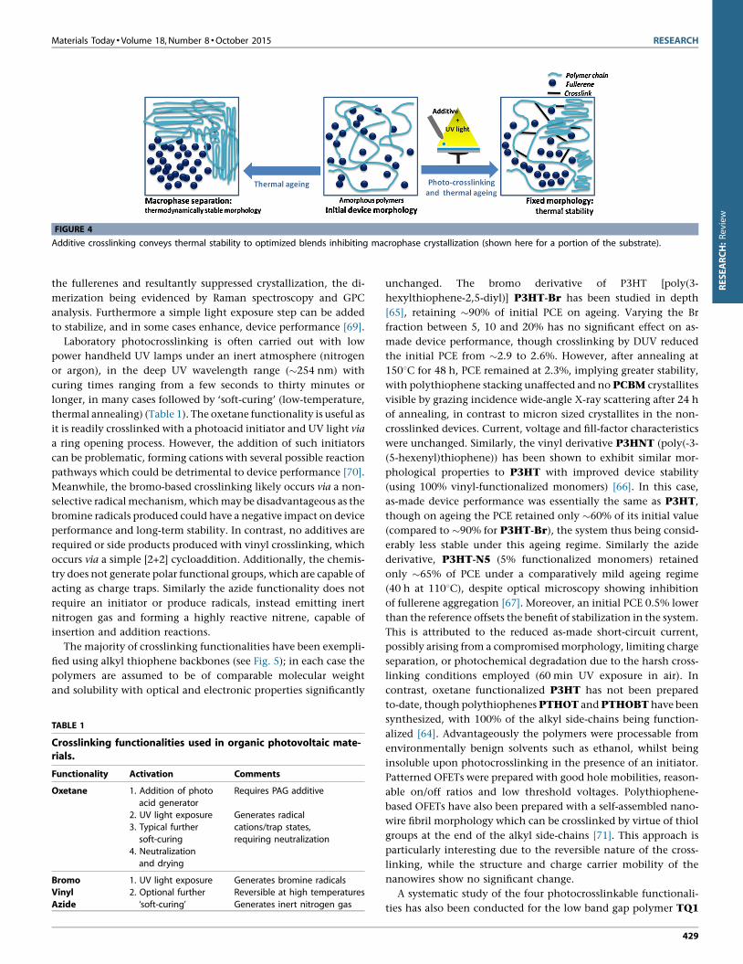
FIGURE 4
Additive crosslinking conveys thermal stability to optimized blends inhibiting macrophase crystallization (shown here for a portion of the substrate).
RESEARCH:Review
the fullerenes and resultantly suppressed crystallization, the di-
merization being evidenced by Raman spectroscopy and GPC
analysis. Furthermore a simple light exposure step can be added
to stabilize, and in some cases enhance, device performance [69].
Laboratory photocrosslinking is often carried out with low
power handheld UV lamps under an inert atmosphere (nitrogen
or argon), in the deep UV wavelength range (�254 nm) with
curing times ranging from a few seconds to thirty minutes or
longer, in many cases followed by ‘soft-curing’ (low-temperature,
thermal annealing) (Table 1). The oxetane functionality is useful as
it is readily crosslinked with a photoacid initiator and UV light via
a ring opening process. However, the addition of such initiators
can be problematic, forming cations with several possible reaction
pathways which could be detrimental to device performance [70].
Meanwhile, the bromo-based crosslinking likely occurs via a non-
selective radical mechanism, which may be disadvantageous as the
bromine radicals produced could have a negative impact on device
performance and long-term stability. In contrast, no additives are
required or side products produced with vinyl crosslinking, which
occurs via a simple [2+2] cycloaddition. Additionally, the chemis-
try does not generate polar functional groups, which are capable of
acting as charge traps. Similarly the azide functionality does not
require an initiator or produce radicals, instead emitting inert
nitrogen gas and forming a highly reactive nitrene, capable of
insertion and addition reactions.
The majority of crosslinking functionalities have been exempli-
fied using alkyl thiophene backbones (see Fig. 5); in each case the
polymers are assumed to be of comparable molecular weight
and solubility with optical and electronic properties significantly
TABLE 1
Crosslinking functionalities used in organic photovoltaic mate-rials.
Functionality Activation Comments
Oxetane 1. Addition of photo
acid generator
Requires PAG additive
2. UV light exposure Generates radical
cations/trap states,
requiring neutralization
3. Typical further
soft-curing
4. Neutralizationand drying
Bromo 1. UV light exposure Generates bromine radicalsVinyl 2. Optional further
‘soft-curing’
Reversible at high temperatures
Azide Generates inert nitrogen gas
unchanged. The bromo derivative of P3HT [poly(3-
hexylthiophene-2,5-diyl)] P3HT-Br has been studied in depth
[65], retaining �90% of initial PCE on ageing. Varying the Br
fraction between 5, 10 and 20% has no significant effect on as-
made device performance, though crosslinking by DUV reduced
the initial PCE from �2.9 to 2.6%. However, after annealing at
1508C for 48 h, PCE remained at 2.3%, implying greater stability,
with polythiophene stacking unaffected and no PCBM crystallites
visible by grazing incidence wide-angle X-ray scattering after 24 h
of annealing, in contrast to micron sized crystallites in the non-
crosslinked devices. Current, voltage and fill-factor characteristics
were unchanged. Similarly, the vinyl derivative P3HNT (poly(-3-
(5-hexenyl)thiophene)) has been shown to exhibit similar mor-
phological properties to P3HT with improved device stability
(using 100% vinyl-functionalized monomers) [66]. In this case,
as-made device performance was essentially the same as P3HT,
though on ageing the PCE retained only �60% of its initial value
(compared to �90% for P3HT-Br), the system thus being consid-
erably less stable under this ageing regime. Similarly the azide
derivative, P3HT-N5 (5% functionalized monomers) retained
only �65% of PCE under a comparatively mild ageing regime
(40 h at 1108C), despite optical microscopy showing inhibition
of fullerene aggregation [67]. Moreover, an initial PCE 0.5% lower
than the reference offsets the benefit of stabilization in the system.
This is attributed to the reduced as-made short-circuit current,
possibly arising from a compromised morphology, limiting charge
separation, or photochemical degradation due to the harsh cross-
linking conditions employed (60 min UV exposure in air). In
contrast, oxetane functionalized P3HT has not been prepared
to-date, though polythiophenes PTHOT and PTHOBT have been
synthesized, with 100% of the alkyl side-chains being function-
alized [64]. Advantageously the polymers were processable from
environmentally benign solvents such as ethanol, whilst being
insoluble upon photocrosslinking in the presence of an initiator.
Patterned OFETs were prepared with good hole mobilities, reason-
able on/off ratios and low threshold voltages. Polythiophene-
based OFETs have also been prepared with a self-assembled nano-
wire fibril morphology which can be crosslinked by virtue of thiol
groups at the end of the alkyl side-chains [71]. This approach is
particularly interesting due to the reversible nature of the cross-
linking, while the structure and charge carrier mobility of the
nanowires show no significant change.
A systematic study of the four photocrosslinkable functionali-
ties has also been conducted for the low band gap polymer TQ1
429
RESEARCH Materials Today �Volume 18, Number 8 �October 2015
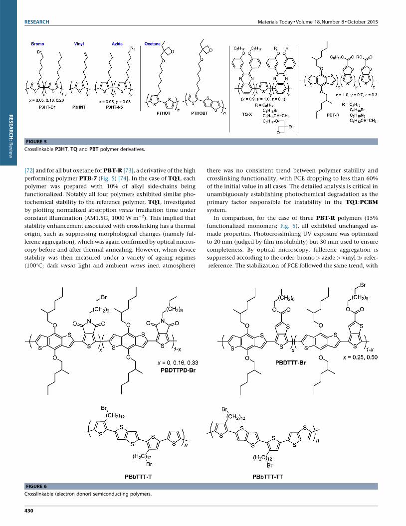
FIGURE 5
Crosslinkable P3HT, TQ and PBT polymer derivatives.
RESEARCH:Review
[72] and for all but oxetane for PBT-R [73], a derivative of the high
performing polymer PTB-7 (Fig. 5) [74]. In the case of TQ1, each
polymer was prepared with 10% of alkyl side-chains being
functionalized. Notably all four polymers exhibited similar pho-
tochemical stability to the reference polymer, TQ1, investigated
by plotting normalized absorption versus irradiation time under
constant illumination (AM1.5G, 1000 W m�2). This implied that
stability enhancement associated with crosslinking has a thermal
origin, such as suppressing morphological changes (namely ful-
lerene aggregation), which was again confirmed by optical micros-
copy before and after thermal annealing. However, when device
stability was then measured under a variety of ageing regimes
(1008C; dark versus light and ambient versus inert atmosphere)
FIGURE 6
Crosslinkable (electron donor) semiconducting polymers.
430
there was no consistent trend between polymer stability and
crosslinking functionality, with PCE dropping to less than 60%
of the initial value in all cases. The detailed analysis is critical in
unambiguously establishing photochemical degradation as the
primary factor responsible for instability in the TQ1:PCBM
system.
In comparison, for the case of three PBT-R polymers (15%
functionalized monomers; Fig. 5), all exhibited unchanged as-
made properties. Photocrosslinking UV exposure was optimized
to 20 min (judged by film insolubility) but 30 min used to ensure
completeness. By optical microscopy, fullerene aggregation is
suppressed according to the order: bromo > azide > vinyl � refer-
reference. The stabilization of PCE followed the same trend, with
Materials Today � Volume 18, Number 8 �October 2015 RESEARCH
RESEARCH:Review
�80% of PCE being retained for PBT-Br after ageing (1508C,
80 h), representing excellent stability without compromising as-
made performance.
The first crosslinkable push-pull type electron donor polymer
reported in the literature was PBDTTPD-Br which exhibited
good long-term thermal stability [61]. Polymers functionalized
with bromine on 16% of the TPD N-alkyl side-chains gave the
highest performance, with average PCE increasing on ageing
(annealing at 1508C for 72 h) from 3.3% to 4.6%, while the
reference cell dropped from 5.2% to 3.9%. The increase in PCE
of the crosslinked cell is attributed to preservation of short-circuit
current, achieved by morphological stabilization on the aggrega-
tion scale, combined with an increase in open-circuit voltage –
which may be attributed to a change in energy of the interfacial
charge-transfer states between the polymer and fullerene compo-
nents – and an 18% increase in FF.
In addition to PBT-R and PBDTTPD-Br polymers, bromo-
functionalized PBDTTT polymers have also been prepared (25%
or 50% brominated TT alkyl side-chains; Fig. 6). UV exposure time
was investigated showing little difference in film retention (on
spin-washing) between 10 and 30 min, but reduced retention after
just 5 min. On annealing the Br-25% device PCE plateaued after
eight hours, retaining �65% of initial PCE, with fullerene aggre-
gation being suppressed. More noteworthy and akin to that afore-
mentioned, initial PCE improved on crosslinking by almost 1%
from 4.3% to 5.2% [75].
In addition, the liquid-crystalline polymer PBbTTT-T and its
analogue PBbTTT-TT have also been prepared (Fig. 6). The
spaced dodecyl alkyl side-chains (100% bromine functionalized)
permit the intercalation of fullerenes that can then be ‘locked’ in
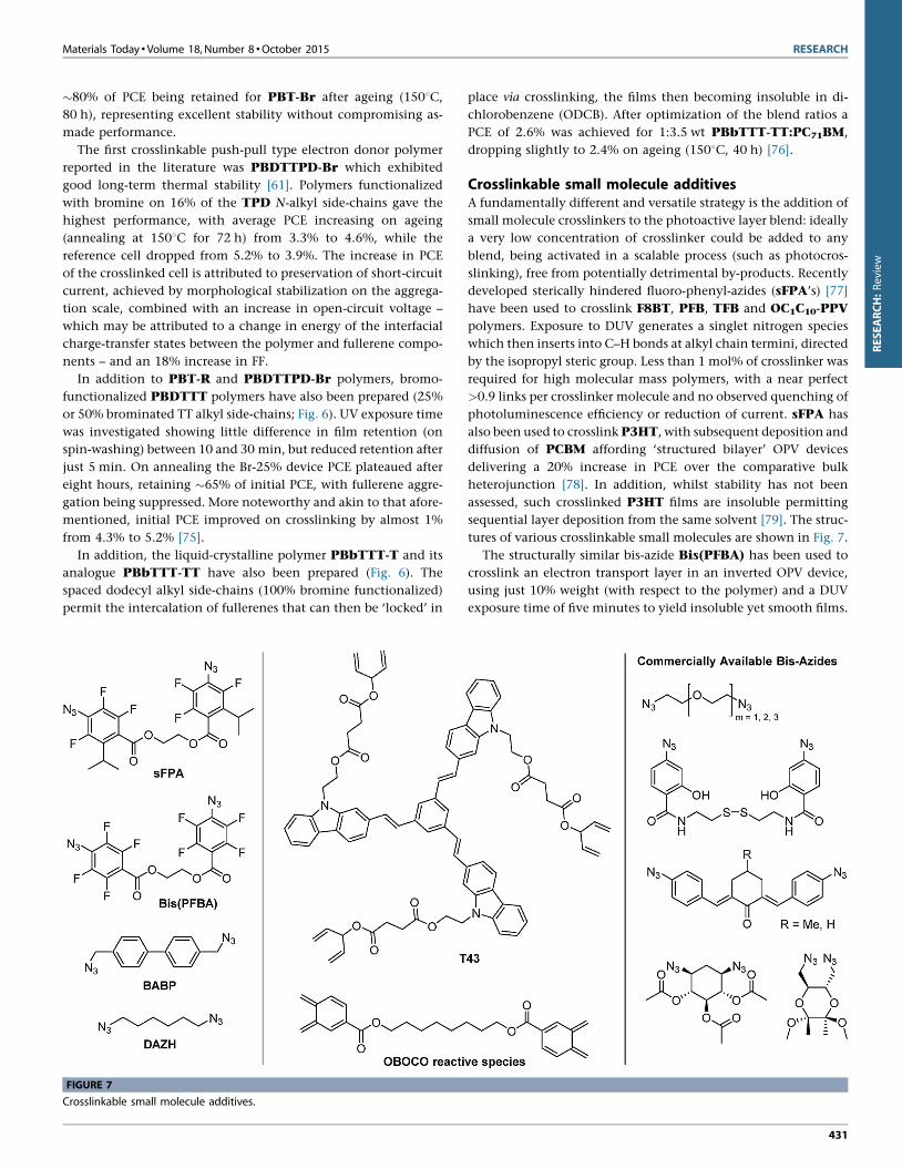
FIGURE 7
Crosslinkable small molecule additives.
place via crosslinking, the films then becoming insoluble in di-
chlorobenzene (ODCB). After optimization of the blend ratios a
PCE of 2.6% was achieved for 1:3.5 wt PBbTTT-TT:PC71BM,
dropping slightly to 2.4% on ageing (1508C, 40 h) [76].
Crosslinkable small molecule additivesA fundamentally different and versatile strategy is the addition of
small molecule crosslinkers to the photoactive layer blend: ideally
a very low concentration of crosslinker could be added to any
blend, being activated in a scalable process (such as photocros-
slinking), free from potentially detrimental by-products. Recently
developed sterically hindered fluoro-phenyl-azides (sFPA’s) [77]
have been used to crosslink F8BT, PFB, TFB and OC1C10-PPV
polymers. Exposure to DUV generates a singlet nitrogen species
which then inserts into C–H bonds at alkyl chain termini, directed
by the isopropyl steric group. Less than 1 mol% of crosslinker was
required for high molecular mass polymers, with a near perfect
>0.9 links per crosslinker molecule and no observed quenching of
photoluminescence efficiency or reduction of current. sFPA has
also been used to crosslink P3HT, with subsequent deposition and
diffusion of PCBM affording ‘structured bilayer’ OPV devices
delivering a 20% increase in PCE over the comparative bulk
heterojunction [78]. In addition, whilst stability has not been
assessed, such crosslinked P3HT films are insoluble permitting
sequential layer deposition from the same solvent [79]. The struc-
tures of various crosslinkable small molecules are shown in Fig. 7.
The structurally similar bis-azide Bis(PFBA) has been used to
crosslink an electron transport layer in an inverted OPV device,
using just 10% weight (with respect to the polymer) and a DUV
exposure time of five minutes to yield insoluble yet smooth films.
431
RESEARCH Materials Today �Volume 18, Number 8 �October 2015
FIGURE 8
Alternative strategies to ‘lock’ morphology in organic semiconducting polymers.
RESEARCH:Review
The result was cells that retained an impressive 90% of their initial
PCE (dropping from 3.4% to just 3.0%) after 20 days storage in air
[80]. Bis-azide BABP has also been used, selectively crosslinking
fullerenes on mild thermal activation in blends with either P3HT,
PTB7 or PDPPTBT to afford 60–90% retention of initial PCE on
thermal ageing, depending on the polymer (see Table 2 for details).
BABP is conveniently handled as a solid – unlike liquid sFPA –
and can be used at just 2% weight addition with respect to the
polymer [81].
We recently demonstrated that solid bis-azide DAZH could be
used to crosslink SiIDT-BT acting as a dual-functional additive,
boosting initial PCE from 6% to 7%. Moreover, after curing and
thermal ageing the crosslinked device retained �85% of initial PCE
compared to <60% for the reference device. The improved stability
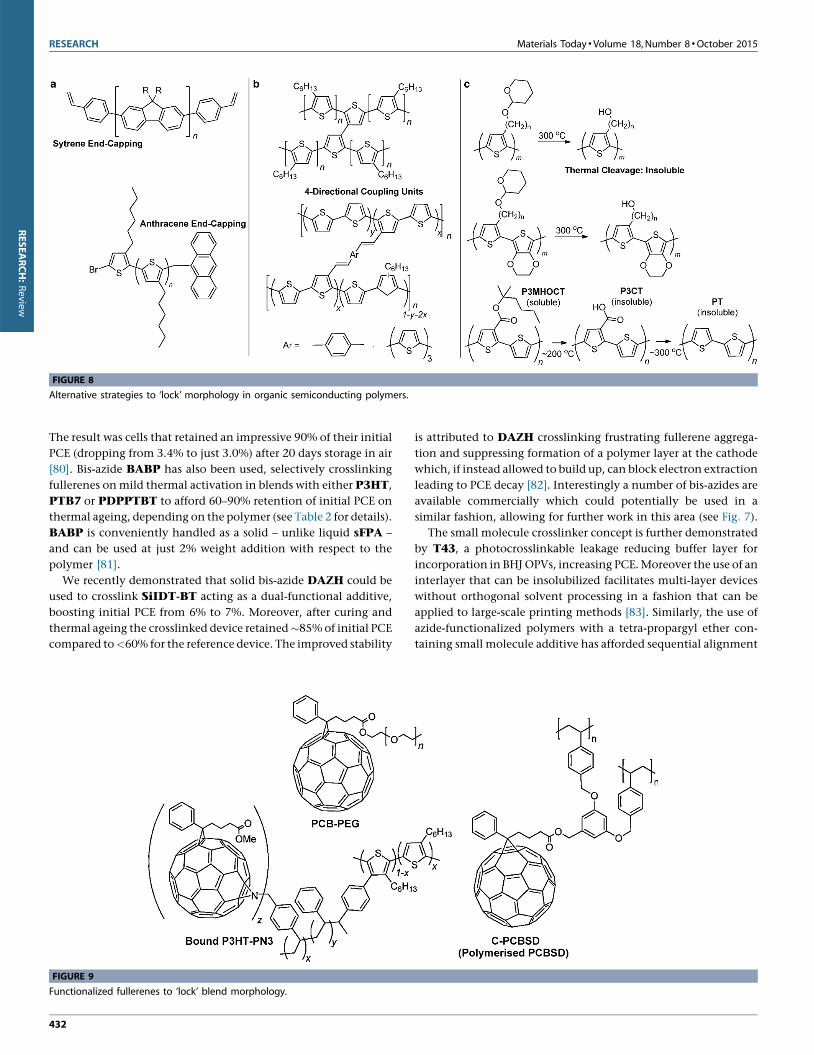
FIGURE 9
Functionalized fullerenes to ‘lock’ blend morphology.
432
is attributed to DAZH crosslinking frustrating fullerene aggrega-
tion and suppressing formation of a polymer layer at the cathode
which, if instead allowed to build up, can block electron extraction
leading to PCE decay [82]. Interestingly a number of bis-azides are
available commercially which could potentially be used in a
similar fashion, allowing for further work in this area (see Fig. 7).
The small molecule crosslinker concept is further demonstrated
by T43, a photocrosslinkable leakage reducing buffer layer for
incorporation in BHJ OPVs, increasing PCE. Moreover the use of an
interlayer that can be insolubilized facilitates multi-layer devices
without orthogonal solvent processing in a fashion that can be
applied to large-scale printing methods [83]. Similarly, the use of
azide-functionalized polymers with a tetra-propargyl ether con-
taining small molecule additive has afforded sequential alignment
Materials Today � Volume 18, Number 8 �October 2015 RESEARCH
RESEARCH:Review
and in situ crosslinking, resulting in long-term microstructure
stability and very high optoelectronic activity at elevated tem-
peratures (858C), highlighting the wide range of materials and
microstructures that can benefit from thermal stabilization by
crosslinking [84].
More recently the molecule OBOCO has been developed. Upon
thermal activation OBOCO undergoes a Diels–Alder reaction with
fullerenes, effectively polymerizing them, exemplified by consis-
tent hole mobility on thermal curing while electron mobility
decreases in a blend with P3HT. While 5% weight OBOCO
additive marginally improves PCE, using more than 5% weight
reduces both fill-factor and short-circuit current density, reducing
PCE. However, open-circuit voltage increases with OBOCO con-
tent up to 20% weight and is stable to ageing, conferring stability
to the OPV cell, which retained 62% of its initial PCE on ageing at
1508C for 4 days, attributed to suppression of fullerene aggregation
as determined by optical microscopy [63].
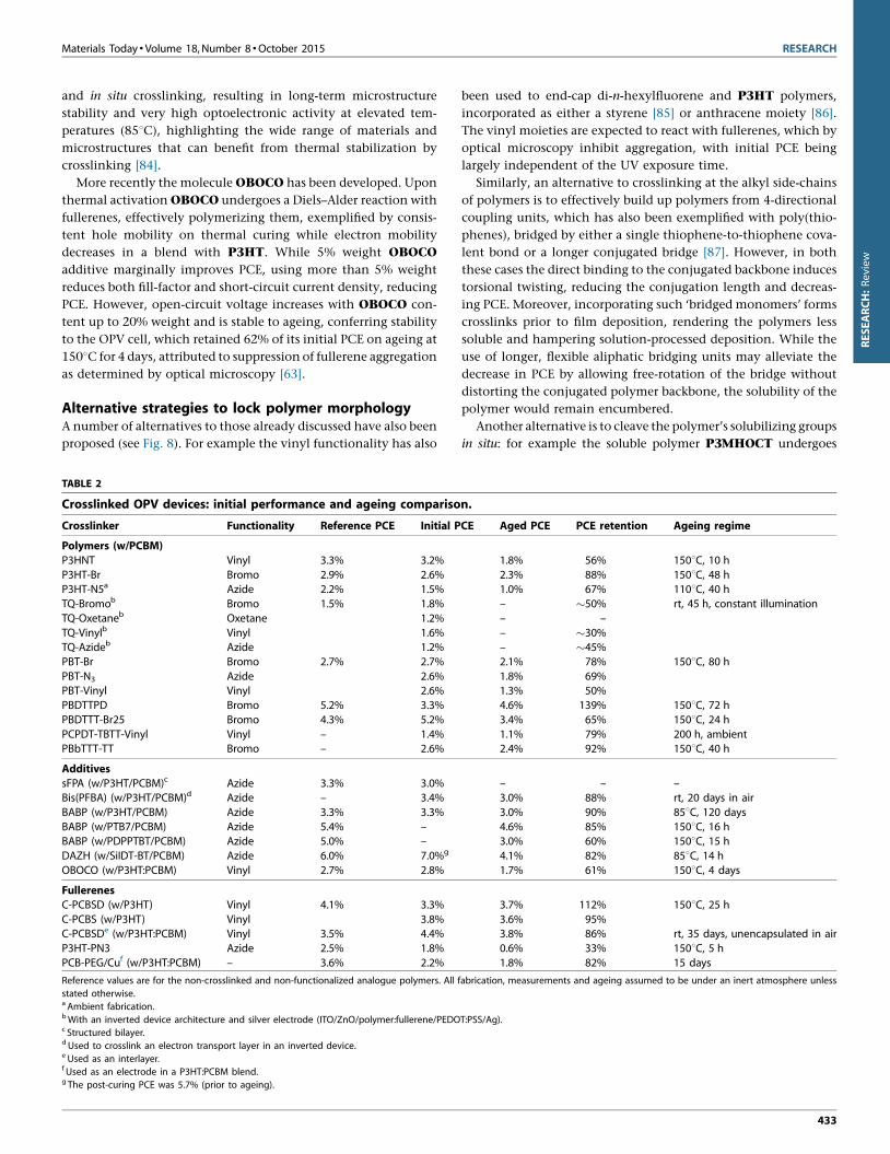
Alternative strategies to lock polymer morphologyA number of alternatives to those already discussed have also been
proposed (see Fig. 8). For example the vinyl functionality has also
TABLE 2
Crosslinked OPV devices: initial performance and ageing compariso
Crosslinker Functionality Reference PCE Initial P
Polymers (w/PCBM)
P3HNT Vinyl 3.3% 3.2%
P3HT-Br Bromo 2.9% 2.6%
P3HT-N5a Azide 2.2% 1.5%
TQ-Bromob Bromo 1.5% 1.8%
TQ-Oxetaneb Oxetane 1.2%
TQ-Vinylb Vinyl 1.6%
TQ-Azideb Azide 1.2%
PBT-Br Bromo 2.7% 2.7%
PBT-N3 Azide 2.6%
PBT-Vinyl Vinyl 2.6%
PBDTTPD Bromo 5.2% 3.3%
PBDTTT-Br25 Bromo 4.3% 5.2%
PCPDT-TBTT-Vinyl Vinyl – 1.4%
PBbTTT-TT Bromo – 2.6%
Additives
sFPA (w/P3HT/PCBM)c Azide 3.3% 3.0%
Bis(PFBA) (w/P3HT/PCBM)d Azide – 3.4%
BABP (w/P3HT/PCBM) Azide 3.3% 3.3%
BABP (w/PTB7/PCBM) Azide 5.4% –
BABP (w/PDPPTBT/PCBM) Azide 5.0% –
DAZH (w/SiIDT-BT/PCBM) Azide 6.0% 7.0%g
OBOCO (w/P3HT:PCBM) Vinyl 2.7% 2.8%
Fullerenes
C-PCBSD (w/P3HT) Vinyl 4.1% 3.3%
C-PCBS (w/P3HT) Vinyl 3.8%
C-PCBSDe (w/P3HT:PCBM) Vinyl 3.5% 4.4%
P3HT-PN3 Azide 2.5% 1.8%
PCB-PEG/Cuf (w/P3HT:PCBM) – 3.6% 2.2%
Reference values are for the non-crosslinked and non-functionalized analogue polymers. All f
stated otherwise.a Ambient fabrication.bWith an inverted device architecture and silver electrode (ITO/ZnO/polymer:fullerene/PEDOc Structured bilayer.d Used to crosslink an electron transport layer in an inverted device.e Used as an interlayer.f Used as an electrode in a P3HT:PCBM blend.g The post-curing PCE was 5.7% (prior to ageing).
been used to end-cap di-n-hexylfluorene and P3HT polymers,
incorporated as either a styrene [85] or anthracene moiety [86].
The vinyl moieties are expected to react with fullerenes, which by
optical microscopy inhibit aggregation, with initial PCE being
largely independent of the UV exposure time.
Similarly, an alternative to crosslinking at the alkyl side-chains
of polymers is to effectively build up polymers from 4-directional
coupling units, which has also been exemplified with poly(thio-
phenes), bridged by either a single thiophene-to-thiophene cova-
lent bond or a longer conjugated bridge [87]. However, in both
these cases the direct binding to the conjugated backbone induces
torsional twisting, reducing the conjugation length and decreas-
ing PCE. Moreover, incorporating such ‘bridged monomers’ forms
crosslinks prior to film deposition, rendering the polymers less
soluble and hampering solution-processed deposition. While the
use of longer, flexible aliphatic bridging units may alleviate the
decrease in PCE by allowing free-rotation of the bridge without
distorting the conjugated polymer backbone, the solubility of the
polymer would remain encumbered.
Another alternative is to cleave the polymer’s solubilizing groups
in situ: for example the soluble polymer P3MHOCT undergoes
n.
CE Aged PCE PCE retention Ageing regime
1.8% 56% 1508C, 10 h
2.3% 88% 1508C, 48 h1.0% 67% 1108C, 40 h
– �50% rt, 45 h, constant illumination
– –
– �30%– �45%2.1% 78% 1508C, 80 h
1.8% 69%1.3% 50%
4.6% 139% 1508C, 72 h
3.4% 65% 1508C, 24 h
1.1% 79% 200 h, ambient2.4% 92% 1508C, 40 h
– – –3.0% 88% rt, 20 days in air
3.0% 90% 858C, 120 days
4.6% 85% 1508C, 16 h3.0% 60% 1508C, 15 h
4.1% 82% 858C, 14 h
1.7% 61% 1508C, 4 days
3.7% 112% 1508C, 25 h
3.6% 95%3.8% 86% rt, 35 days, unencapsulated in air
0.6% 33% 1508C, 5 h
1.8% 82% 15 days
abrication, measurements and ageing assumed to be under an inert atmosphere unless
T:PSS/Ag).
433
RESEARCH Materials Today �Volume 18, Number 8 �October 2015
RESEARCH:Review
thermal treatment at �2008C then �3008C to afford insoluble
poly(thiophene). However, this also reduces PCE [88].
Fullerene-based crosslinking strategiesThe use of crosslinkable and immobilized fullerene-derived elec-
tron acceptor materials has also been studied (see Fig. 9). One
approach is to polymerize the fullerenes in situ, for example bis-
styryl PCBSD [89], resulting in a highly inter-locked network on
thermal annealing in a blend with P3HT (1808C for 30 min). A
PCE of �3.7% was achieved after ageing (1508C for 25 h) being
higher than the as-made value of �3.3%. Furthermore, similar
performance and stability was observed when using the mono-
styryl analogue PCBS (3.7–3.6% PCE over the same ageing re-
gime), with an optimized weight ratio of 6:5:1 P3HT/PCBM/
Functionalized-PCBM. Whilst initial performance was lowered
in both cases, stability was greatly improved compared to the
reference (which decreased from 4.1% to 0.7%), being attributable
to immobilization of the fullerenes, thus suppressing crystalliza-
tion [62].
Instead of polymerizing the fullerene directly, it is also possible
to functionalize the polymer with well-spaced crosslinking groups
that can selectively bind, as demonstrated with P3HT-PN3, which
uses an azide and poly(phenylethylene) spacer grafted onto 1% of
P3HT repeat units. However, p-binding of the azide to the fuller-
ene lowered the initial PCE by �0.7% and the deterioration of PCE
over time was only marginally suppressed [90].
Alternatively, functionalized fullerenes can be used as proces-
sing additives to improve stability: the addition of 5% by weight
PCB-PEG leads to a spontaneous vertical phase separation and
formation of a covering protective monolayer which both
improves thermal stability and efficiency. PCE rises in comparison
to the reference P3HT:PCBM device by 0.8% (from 3.6% to 4.4%)
with a high voltage, current and fill-factor in optimized devices. In
addition, whilst initial PCE is reduced, with a copper electrode
80% is retained after 360 h, compared to just 20% with an alu-
minium electrode, serving as a promising example of additional
device enhancement [91].
Crosslinked OPV devices summary tableThe initial and aged performance of the various crosslinked OPV
devices described above are summarized in Table 2.
Conclusions and outlookIn summary, state-of-the-art crosslinking strategies utilize UV or
thermal treatment that have demonstrated the potential to be
incorporated into large-scale solution processed manufacturing
methods. Crosslinks are desirably formed at locations which don’t
perturb the conjugated system of both components and critical
microstructure of the active blend. This is optimally between the
termini of solubilizing alkyl side-chains, via either attached func-
tional groups (bromo/oxetane/vinyl/azide) or selective small mol-
ecule crosslinkers (2-, 3- or 4-D coupling units) which may be
added to a blend solution. To-date the bromo functionality typi-
cally confers the greatest stability. It is often necessary to perform
crosslinking under an inert atmosphere (to avoid photo-oxida-
tion) and this could densify the polymer network improving
packing and solid state interactions, boosting short-circuit current
and thus initial PCE but at the risk of electrode delamination.
434
Alternative approaches have lower crosslinking densities, require
harsh heat treatments and can encumber device efficiency, or
involve expensive fullerene derivatives. However, these important
research fields require further study and optimization.
While functionalized polymers may be more readily character-
ized, the use of multi-directional (>2D) crosslinking small mole-
cule additives is of interest due to their greater versatility, as well as
optimization of existing materials processing and synthesis.
References
[1] Chemistry Nobel Prize 2000.
[2] M. Pagliaro, G. Palmisano, R. Ciriminna, Flexible Solar Cells, Wiley-VCH, Wein-
heim, 2008.
[3] J. Rivnay, R.M. Owens, G.G. Malliaras, Chem. Mater. 26 (2014) 679.
[4] BASF, BASF Chemistry World Tour Innovations, 2013.
[5] G. Dennler, M.C. Scharber, C.J. Brabec, Adv. Mater. 21 (2009) 1323.
[6] A. Facchetti, Chem. Mater. 23 (2011) 733.
[7] H. Zhou, L. Yang, W. You, Macromolecules 45 (2012) 607.
[8] T.D. Nielsen, et al. Sol. Energy Mater. Sol. Cells 94 (2010) 1553.
[9] Mitsubishi Chemical Corporation No Title.
[10] J. You, et al. Nat. Commun. 4 (2013) 1446.
[11] J. You, et al. Adv. Mater. (Deerfield Beach, Fla.) 25 (2013) 3973.
[12] C.J. Brabec, et al. Adv. Mater. 22 (2010) 3839.
[13] M. Jørgensen, et al. Adv. Mater. (Deerfield Beach, Fla.) 24 (2012) 580.
[14] J. Ahmad, et al. Renew. Sust. Energy Rev. 27 (2013) 104.
[15] J.U. Lee, et al. J. Mater. Chem. 22 (2012) 24265.
[16] L. Dou, et al. Adv. Mater. (Deerfield Beach, Fla.) 25 (2013) 6642.
[17] H.J. Son, et al. Energy Environ. Sci. 5 (2012) 8158.
[18] A.J. Heeger, Adv. Mater. (Deerfield Beach, Fla.) 26 (2014) 10.
[19] C.L. Chocos, S.A. Choulis, Prog. Polym. Sci. 36 (2011) 1326.
[20] M.T. Dang, et al. Chem. Rev. 133 (2013) 3734.
[21] P.P. Khlyabich, et al. Polymer (2013).
[22] W. Ma, et al. Adv. Funct. Mater. 15 (2005) 1617.
[23] L. Lu, L. Yu, Adv. Mater. (2014).
[24] Z. He, et al. Nat. Photon. 9 (2015) 174.
[25] P. Liu, et al. Chem. Mater. (2014).
[26] C. Cabanetos, et al. J. Am. Chem. Soc. 135 (2013) 4656.
[27] X. Hu, et al. Adv. Energy Mater. (2014).
[28] X. Guo, et al. Nat. Photon. 7 (2013) 825.
[29] K.-S. Chen, et al. Adv. Mater. (2014).
[30] R.S. Ashraf, et al. J. Am. Chem. Soc. 137 (2015) 1314.
[31] Y. Liu, et al. Nat. Commun. 5 (2014) 5293.
[32] J. You, et al. Prog. Polym. Sci. 38 (2013) 1909.
[33] W. Li, et al. J. Am. Chem. Soc. 135 (2013) 5529.
[34] L.T. Dou, et al. Nat. Photon. 6 (2012) 180.
[35] L. Dou, et al. J. Am. Chem. Soc. 134 (2012) 10071.
[36] L.T. Dou, et al. Adv. Mater. 25 (2013) 825.
[37] K. Li, et al. J. Am. Chem. Soc. 135 (2013) 13549.
[38] J. You, et al. Adv. Mater. 25 (2013) 3973.
[39] J.B. You, et al. Nat. Commun. 4 (2013) 1446.
[40] A. Mishra, P. Bauerle, Angew. Chem. Int. Ed. 51 (2012) 2020.
[41] M. Riede, et al. Adv. Funct. Mater. 21 (2011) 3019.
[42] A. Facchetti, Mater. Today 16 (2013) 123.
[43] P.D. Topham, A.J. Parnell, R.C. Hiorns, J. Polym. Sci. B: Polym. Phys. 49 (2011)
1131.
[44] P. Sonar, J.P.F. Lim, K.L. Chan, Energy Environ. Sci. 4 (2011) 1558.
[45] A.F. Eftaiha, et al. J. Mater. Chem. A 2 (2014) 1201.
[46] S. Holliday, et al. J. Am. Chem. Soc. 137 (2015) 898.
[47] C.B. Nielsen, et al. Adv. Mater. 27 (2015) 948.
[48] M.J. Robb, et al. J. Polym. Sci. A: Polym. Chem. 51 (2013) 1263.
[49] J. Rivnay, et al. Chem. Rev. 112 (2012) 5488.
[50] R. Noriega, et al. Nat. Mater. 12 (2013) 1038.
[51] M.-S. Kim, et al. Appl. Phys. Lett. 90 (2007) 123113.
[52] N. Haberkorn, S.A.L. Weber, P. Theato, ACS Appl. Mater. Interfaces 2 (2010) 1573.
[53] N. Haberkorn, et al. Macromol. Chem. Phys. 212 (2011) 2142.
[54] J. Peet, et al. Nat. Mater. 6 (2007) 497–500.
[55] H. Kim, W.-W. So, S.-J. Moon, J. Kor. Phys. Soc. 48 (2006) 441.
[56] S.M. Lindner, et al. Angew. Chem. Int. Ed. 45 (2006) 3364.
[57] C. Goh, K.M. Coakley, M.D. McGehee, Nano Lett. 5 (2005) 1545.
[58] H.J. Snaith, et al. Nano Lett. 5 (2005) 1653.
Materials Today � Volume 18, Number 8 �October 2015 RESEARCH
ESEARCH:Review
[59] M. Jørgensen, et al. Adv. Mater. 24 (2012) 580.
[60] S. Cros, et al. Sol. Energy Mater. Sol. Cells 95 (2011) 865.
[61] G. Griffini, et al. Adv. Mater. (Deerfield Beach, Fla.) 23 (2011) 1660–1664.
[62] Y.-J. Cheng, et al. Adv. Funct. Mater. 21 (2011) 1723.
[63] D. He, et al. J. Mater. Chem. A 1 (2013) 4589.
[64] K. Lu, et al. Macromolecules 42 (2009) 3222.
[65] B.J. Kim, et al. Adv. Funct. Mater. 19 (2009) 2273.
[66] S. Miyanishi, K. Tajima, K. Hashimoto, Macromolecules 42 (2009) 1610.
[67] C.-Y. Nam, et al. Macromolecules 45 (2012) 2338.
[68] F. Piersimoni, et al. J. Polym. Sci. B: Polym. Phys. 51 (2013) 1209.
[69] Z. Li, et al. Nat. Commun. 4 (2013) 2227.
[70] S. Feser, K. Meerholz, Chem. Mater. 23 (2011) 5001.
[71] B.A.G. Hammer, et al. ACS Appl. Mater. Interfaces 6 (2014) 7705.
[72] J.E. Carle, et al. J. Mater. Chem. 22 (2012) 24417.
[73] X. Chen, L. Chen, Y. Chen, J. Polym. Sci. A: Polym. Chem. 51 (2013) 4515.
[74] Y. Liang, et al. Adv. Mater. 22 (2010) E135.
[75] D. Qian, et al. J. Polym. Sci. A: Polym. Chem. 51 (2013) 3123.
[76] K. Yao, et al. Org. Electron. 13 (2012) 1443.
[77] R.-Q. Png, et al. Nat. Mater. 9 (2010) 152.
[78] B. Liu, et al. Nat. Commun. 3 (2012) 1321.
[79] C. Tao, et al. Adv. Energy Mater. 3 (2013) 105.
[80] N. Cho, et al. Adv. Energy Mater. 1 (2011) 1148.
[81] L. Derue, et al. Adv. Mater. 26 (2014) 5831.
[82] J.W. Rumer, et al. Adv. Energy Mater. (2015).
[83] N. Su Kang, et al. Sol. Energy Mater. Sol. Cells 95 (2011) 2831.
[84] Z. Shi, et al. ACS Macro Lett. 1 (2012) 793.
[85] G. Klarner, et al. Chem. Mater. 11 (1999) 1800.
[86] S. Khiev, et al. Polym. Chem. 4 (2013) 4145.
[87] E. Zhou, et al. Macromolecules 40 (2007) 1831.
[88] J.L. Brusso, M.R. Lilliedal, S. Holdcroft, Polym. Chem. 2 (2011) 175.
[89] C.-H. Hsieh, et al. J. Am. Chem. Soc. 132 (2010) 4887.
[90] B. Gholomkhass, S. Holdcroft, Chem. Mater. 22 (2010) 5371.
[91] J.W. Jung, J.W. Jo, W.H. Jo, Adv. Mater. 23 (2011) 1782.
435
R