NFPA 1981 - مشاوره و خدمات آتش نشانی,تاسیسات و ایمنی...
119
Copyright NFPA N FPA 1981 Standard on OpenCircuit SelfContained Breathing Apparatus (SCBA) for Emergency Services 2007 Edition Copyright © 2007 National Fire Protection Association. All Rights Reserved. This edition of NFPA 1981, Standard on OpenCircuit SelfContained Breathing Apparatus (SCBA) for Emergency Services , was prepared by the Technical Committee on Respiratory Protection Equipment and released by the Technical Correlating Committee on Fire an d Emergency Services Protective Clothing and Equipment. It was issued by the Standards Council on December 1, 2006, with an effective date of December 20, 2006, and supersedes all previous editions. This edition of NFPA 1981 was approved as an American National Standard on December 20, 2006. Origin and Development of NFPA 1981 The first NFPA document to address fire fighter respiratory protection was NFPA 19B, Standard on Respiratory Protective Equipment for Fire Fighters . NFPA 19B was adopted on May 17, 1971, at the Association’s Annual Meeting in San Francisco, California. It was developed by the Sectional Committee on Protective Equipment for Fire Fighters of the Technical Committee on Fire Department Equipment. After 1975, the Sectional Committee was removed from the Technical Committee on Fire Department Equipment and made i ts own technical committee. The main thrust of NFPA 19B was to prohibit filtertype canister masks for fire fighters and permit only selfcontained breathing apparatus. NFPA 19B was officially withdrawn by the Association on May 19, 1981, at the Annual Mee ting in Dallas, Texas. NFPA 1981, Standard on SelfContained Breathing Apparatus for Fire Fighters, was adopted at the same meeting to replace NFPA 19B. That first edition of NFPA 1981 essentially specified NIOSH/MSHAapproved SCBA with a minimum rated service life of 30 minutes . Opencircuit SCBA was required to be positive pressure. The Technical Committee on Protective Equipment for Fire Fighters undertook a complete revision of NFPA 1981 to state performance requirements and appropriate testing
Transcript of NFPA 1981 - مشاوره و خدمات آتش نشانی,تاسیسات و ایمنی...

Copyright NFPA
NFPA 1981 Standard on
OpenCircuit SelfContained Breathing Apparatus (SCBA)
for Emergency Services
2007 Edition
Copyright © 2007 National Fire Protection Association. All Rights Reserved.
This edition of NFPA 1981, Standard on OpenCircuit SelfContained Breathing Apparatus (SCBA) for Emergency Services, was prepared by the Technical Committee on Respiratory Protection Equipment and released by the Technical Correlating Committee on Fire and Emergency Services Protective Clothing and Equipment. It was issued by the Standards Council on December 1, 2006, with an effective date of December 20, 2006, and supersedes all previous editions.
This edition of NFPA 1981 was approved as an American National Standard on December 20, 2006.
Origin and Development of NFPA 1981
The first NFPA document to address fire fighter respiratory protection was NFPA 19B, Standard on Respiratory Protective Equipment for Fire Fighters. NFPA 19B was adopted on May 17, 1971, at the Association’s Annual Meeting in San Francisco, California. It was developed by the Sectional Committee on Protective Equipment for Fire Fighters of the Technical Committee on Fire Department Equipment. After 1975, the Sectional Committee was removed from the Technical Committee on Fire Department Equipment and made its own technical committee. The main thrust of NFPA 19B was to prohibit filtertype canister masks for fire fighters and permit only selfcontained breathing apparatus. NFPA 19B was officially withdrawn by the Association on May 19, 1981, at the Annual Meeting in Dallas, Texas.
NFPA 1981, Standard on SelfContained Breathing Apparatus for Fire Fighters, was adopted at the same meeting to replace NFPA 19B. That first edition of NFPA 1981 essentially specified NIOSH/MSHAapproved SCBA with a minimum rated service life of 30 minutes. Opencircuit SCBA was required to be positive pressure.
The Technical Committee on Protective Equipment for Fire Fighters undertook a complete revision of NFPA 1981 to state performance requirements and appropriate testing

Copyright NFPA
procedures designed to simulate various environmental conditions to which fire fighters’ SCBA can be exposed during use and storage. These requirements are in addition to the basic NIOSH/MSHA certification requirements, and now NFPA 1981 applies to opencircuit SCBA.
The second edition of NFPA 1981 was completed in March 1986 and adopted by the Association at the 1987 Annual Meeting in Cincinnati, Ohio.
After the second edition, the name of the Technical Committee was changed to Fire Service Protective Clothing and Equipment, and a standing Subcommittee on SelfContained Breathing Apparatus was established.
The third edition, in 1992, incorporated new requirements for thirdparty certification and quality control, as well as a new total heat and flame test for the entire apparatus. Other test methods covering facepiece lens abrasion and communications were revised.
The third edition was completed in December 1991 and presented to the Association at the 1992 Annual Meeting in New Orleans, Louisiana.
In January 1995, the Standards Council reorganized the entire project for fire service protective clothing and equipment. The new project was given a Technical Correlating Committee on Fire and Emergency Services Protective Clothing and Equipment and seven technical committees operating within the project. The former standing Subcommittee on SelfContained Breathing Apparatus was changed to the new Technical Committee on Respiratory Protection and Personal Alarm Equipment.
The fourth edition, presented to the Association membership at the 1997 Annual Meeting in Los Angeles, California, incorporated new requirements for surrogate cylinders to replace the actual breathing gas cylinders during the vibration testing to ensure a higher level of safety during this rigorous test. A new requirement for redundant endofservicetime indicators (EOSTI) was added to provide a better level of safety in case of failure of one endofservicetime indicator.
The fifth edition of NFPA 1981 was presented to the NFPA membership at the 2002 Annual Meeting in Minneapolis, Minnesota, on May 19, 2002. That edition incorporated new requirements for headsup displays (HUD) that provide visual information and warnings to SCBA wearers of the status of the SCBA’s air supply and, where the HUD is powered by a power source, the power source status. Those new requirements were in response to fire service requests for the provision of userfriendly information for SCBA wearers so they can better understand their environment and limitations.
Also in response to strong fire service input to the Committee, new requirements were specified for a single universal air connection located in a specific position on all new SCBA certified as compliant with the 2002 edition of NFPA 1981, and existing SCBA that could be upgraded and certified as compliant with the 2002 edition of NFPA 1981. The RIC UAC [RIC stands for rapid intervention company or crew (sometimes called RIT for rapid intervention team, or FAST company or crew); UAC stands for universal air connection] permits the breathing air cylinder of an SCBA user to be replenished from an independent rescue breathing air supply source when the SCBA user is trapped or unable to be removed from a hazardous atmosphere. The RIC UAC does not take breathing air from an SCBA

Copyright NFPA
being worn by a member of the rescue operation but replenishes the victim’s breathing air cylinder from a source of “rescue breathing air,” such as a rescue breathing air cylinder or a highpressure breathing air supply line. The RIC UAC is not a “buddy breathing” device — it does not permit the sharing of a single SCBA breathing air source between two persons. NIOSH does not permit or certify any buddy breathing system that allows two users to share a single breathing air source. Because NFPA 1981 requires NIOSH certification as a prerequisite to become certified as compliant with NFPA 1981, NFPA cannot permit buddy breathing systems, which would be in violation of NIOSH regulations.
The Committee continued to review and revise text for improved clarity and specificity, improved accuracy in testing and test result reporting, and added additional criteria to better evaluate and test the EOSTI.
In 2002, NFPA revised the format for its codes and standards, resulting in chapter, section, and paragraph numbers not matching or corresponding to those of previous editions.
This 2007 edition of NFPA 1981, the sixth edition, represents a complete revision and retitling of the standard as NFPA 1981, Standard on OpenCircuit SelfContained Breathing Apparatus (SCBA) for Emergency Services.
While the Committee has made several significant changes to the standard, a major change in this 2007 edition is the mandatory requirement for all emergency services SCBA to also be NIOSH certified as CBRN SCBA in accordance with the NIOSH Statement of Standard for NIOSH CBRN SCBA Testing. This requirement provides respiratory protection from CBRN terrorism agents (specified chemicals, biological agents, and radiological particulates) that could be released as a result of a terrorism attack.
Although major metropolitan areas are more likely targets of a terrorist event, emergency responders from smaller communities could be called upon to respond to urban areas where the emergency services have become overwhelmed by a terrorist incident. Terrorists themselves might be residing in smaller communities while they await the opportunity to strike, and if they have chemical, biological, or nuclear material in their possession, the possibility of exposure is even greater for those small, rural areas. Terrorist attacks aside, CBRNcertified SCBA offer greater protection for emergency services personnel at minimal cost.
CBRN certification offers verification of enhanced protection for emergency responders that is not otherwise available. Without CBRN protection evaluation, SCBA components are not tested for permeation, penetration, corrosion resistance, or other detrimental effects from exposure to toxic industrial chemicals during hazardous materials incidents and hazardous chemical warfare atmospheres. NIOSH benchmark testing of nonCBRNhardened SCBA against CBRN agents demonstrated that chemical warfare agents (CWA) could cause catastrophic failures within minutes of exposure.
NIOSH’s selection of the test challenge agents for CBRN protection was based on a comprehensive review of available technical data and consultations with other government agencies [e.g., Department of Defense (DoD), Department of Justice (DoJ), and Department of Energy (DoE)]. Various chemical data lists were analyzed, including lists from the Environmental Protection Agency (EPA); the Agency for Toxic Substances and Disease
Copyright NFPA
Registry (ATSDR); NFPA 1994, Standard on Protective Ensembles for First Responders to CBRN Terrorism Incidents; the U.S. Army Center for Health Promotion and Preventative Medicine (USACHPPM) Technical Guide 244; and other, classified sources. That analysis identified a total of 151 toxic industrial chemicals (TICs) and CWA as potential candidates for challenge agents. The candidate agents were evaluated for permeation (molecularly diffusing through material) and penetration (seeping through interfacing components) characteristics as part of a review of their physical properties. This evaluation concluded that Sarin (GB) and sulfur mustard (HD) could be selected as the two representative agents for the penetration/permeation test for the complete listing of 151 CWA and TICs due to their physical properties and molecular structure. NIOSH is unaware of any data that indicate that CBRNcertified SCBA provide less protection against TICs than their industrial counterparts.
The evaluation for CBRN protection provides verification and assurance that the component and material combinations in the approved SCBA configurations provide high resistance to permeation and penetration of hazardous atmospheres of TICs and materials into the breathing air. This is of importance to all responders subject to extreme exposures to any hazardous industrial chemicals and materials.
In addition to the new CBRN requirement, the following significant requirements were added to increase the safety to the users of emergency services SCBA and to better assure the proper functioning of the SCBA:
(1) New breathing air cylinder retention requirement within the mounted position
(2) Mechanical voice diaphragm performance requirement increased to 80 percent minimum score at 1.5 m (4.9 ft) distance
(3) New voice communications system with at least an 85 percent score at 3 m (10 ft) distance
(4) New independent pressure gauge that would not be affected by failure of the headsup display (HUD)
(5) New water immersion requirements for electronic devices that are part of the SCBA that must function properly and remain watertight after six exposures to 177°C (350°F) for 15 minutes and water submersion to 1.5 m (4.9 ft)
(6) New low power capacity requirements for electronic devices to assure that such devices will continue to function properly for at least 2 hours following activation of the low power source signal
Special recognition is given to Committee Chair Ray Reed, who is leaving the Committee. Ray, a Battalion Chief and the Safety Officer for Dallas (Texas) Fire and Rescue, is retiring from DFR after 33½ years of service. He joined the NFPA committees that develop standards for fire service protective clothing and equipment in 1990 and became the Chair of the Technical Committee on Respiratory Protection Equipment in January 1997. Ray’s dedication and leadership to fire service safety have greatly enhanced safety for all fire fighters. Many improvements to fire and emergency services SCBA have evolved during his tenure on this Committee. He also contributed his considerable expertise in several different

Copyright NFPA
areas of protective clothing and equipment within the overall Project. Ray’s professionalism and tireless efforts to improve fire service safety are an outstanding credit to him and to Dallas Fire and Rescue. Ray, we extend best wishes for a long and healthy life and a wonderful retirement with your family. Please accept our sincerest thanks for all you have done for the fire and emergency services.
In Memoriam, 11 September 2001
We pay tribute to the 343 members of FDNY who gave their lives to save civilian victims on 11 September 2001, at the World Trade Center. They are true American heroes in death, but they were also American heroes in life. We will keep them in our memory and in our hearts. They are the embodiment of courage, bravery, and dedication. May they rest in peace.
Technical Correlating Committee on Fire and Emergency Services Protective Clothing and Equipment (FAEAAC)
Richard M. Duffy, Chair International Association of Fire Fighters, DC [L]
William M. Lambert, Secretary Mine Safety Appliances Company, PA [M]
Rep. Compressed Gas Association
Leslie Anderson, U.S. Department of Agriculture, MT [E]
Roger L. Barker, North Carolina State University, NC [SE]
Les Boord, U.S. Department of Health and Human Services, PA [E]
Steven D. Corrado, Underwriters Laboratories Incorporated, NC [RT]
Nicholas J. Curtis, Lion Apparel, Incorporated, OH [M]
Robert A. Freese, Globe Manufacturing Company, NH [M]
Andy Gbur, Intertek, OH [RT]
Bill Grilliot, TFG/Morning Pride Manufacturing, LLC, OH [M] Rep. Fire and Emergency Manufacturers and Services Association Incorporated
Kimberly M. Henry, PBI Performance Products, Incorporated, NC [M]
James S. Johnson, Lawrence Livermore National Laboratory, CA [RT]
Cy Long, Texas Commission on Fire Protection, TX [E]
David G. Matthews, Fire & Industrial (P.P.E.) Limited, United Kingdom [SE]

Copyright NFPA
Rep. International Standards Organization
Jim Minx, Oklahoma State Firefighters Association, OK [C]
Gary L. Neilson, Reno Fire Department, NV [U]
Stephen R. Sanders, Safety Equipment Institute (SEI), VA [RT]
Denise N. Statham, Southern Mills, Incorporated, GA [M]
Jeffrey O. Stull, International Personnel Protection, Incorporated, TX [SE]
David Trivette, Tyco/Scott Health & Safety, NC [M] Rep. International Safety Equipment Association
Robert D. Tutterow, Jr., Charlotte Fire Department, NC [U] Rep. Fire Industry Equipment Research Organization
Harry P. Winer, U.S. Department of the Navy, MA [RT]
Alternates
Jason L. Allen, Intertek, NY [RT] (Alt. to A. Gbur)
Eric J. Beck, Mine Safety Appliances Company, PA [M] (Alt. to W. M. Lambert)
Janice C. Bradley, International Safety Equipment Association, VA [M] (Alt. to D. Trivette)
Patricia A. Freeman, Globe Manufacturing Company, Incorporated, NH [M] (Alt. to R. A. Freese)
Patricia A. Gleason, Safety Equipment Institute (SEI), VA [RT] (Alt. to S. R. Sanders)
Mary I. Grilliot, TFG/Morning Pride Manufacturing LLC, OH [M] (Alt. to B. Grilliot)
William E. Haskell, III, U.S. Department of Health and Human Services, MA [E] (Alt. to L. Boord)
Steven B. Lumry, Oklahoma City Fire Department, OK [C] (Alt. to J. Minx)
Andrew P. Perrella, E. I. DuPont Company, DE [M]

Copyright NFPA
(Alt. to K. M. Henry)
Frank P. Taylor, Lion Apparel, Incorporated, VA [M] (Alt. to N. J. Curtis)
Nonvoting
Donna P. Brehm, Virginia Beach Fire Department, VA [U] Rep. TC on Emergency Medical Services Protective Clothing and Equipment
Dean W. Cox, Fairfax County Fire and Rescue Department, VA [U] Rep. TC on Special Operations Protective Clothing and Equipment
Glenn P. Jirka, Miami Township Fire and EMS Division, OH [E] Rep. TC on Hazardous Materials Protective Clothing and Equipment
Kirk Owen, Plano Fire Department, TX [U] Rep. TC on Structural and Proximity Fire Fighting Protective Clothing and Equipment
Ray F. Reed, Dallas Fire Rescue, TX [U] Rep. TC on Respiratory Protection Equipment
Bruce H. Varner, Santa Rosa Fire Department, CA [E] Rep. TC on Electronic Safety Equipment
Bruce W. Teele, NFPA Staff Liaison
This list represents the membership at the time the Committee was balloted on the final text of this edition. Since that time, changes in the membership may have occurred. A key to classifications is found at the back of the document.
NOTE: Membership on a committee shall not in and of itself constitute an endorsement of the Association or any document developed by the committee on which the member serves.
Committee Scope: This Committee shall have primary responsibility for documents on the design, performance, testing, and certification of protective clothing and protective equipment manufactured for fire and emergency services organizations and personnel, to protect against exposures encountered during emergency incident operations. This Committee shall also have the primary responsibility for documents on the selection, care, and maintenance of such protective clothing and protective equipment by fire and emergency services organizations and personnel.
Technical Committee on Respiratory Protection Equipment (FAERPE)
Ray F. Reed, Chair Dallas Fire Rescue, TX [U]
W. Lee Birch, Secretary Luxfer Gas Cylinders, CA [M]

Copyright NFPA
Jason L. Allen, Intertek, NY [RT]
Claire C. Austin, National Research Council of Canada (NRC), Canada [SE]
Neal A. Baluha, Palm Beach County Fire Rescue, FL [C]
Eric J. Beck, Mine Safety Appliances Company, PA [M]
David T. Bernzweig, Columbus, Ohio Division of Fire, OH [L] Rep. Columbus Fire Fighters Union, IAFF Local 67
Les Boord, U.S. Department of Health and Human Services, PA [E]
A. Paul Bull, Fairfax County Fire and Rescue Department, VA [U]
Brian H. Cox, Clovis Fire Department, CA [U]
Edward D. Golla, TRI/Airtesting, TX [RT]
A. Ira Harkness, U.S. Department of the Navy, FL [RT]
David V. Haston, U.S. Department of Agriculture, CA [RT]
John Jarboe, Grace Industries, Incorporated, MD [M]
Stephen J. King, Deer Park, NY [SE]
Kevin D. Lentz, City of Garland Texas Fire Department, TX [U]
Ian Maxwell, Interspiro AB, Sweden [M]
Stephen T. Miles, City of Virginia Beach Fire Department, VA [U]
Jerry Phifer, Tyco/Scott Health & Safety, NC [M]
Fred H. Rascoe, International Safety Instruments, Incorporated, GA [M]
Daniel N. Rossos, City of Portland Fire Bureau, OR [U]
Stephen R. Sanders, Safety Equipment Institute (SEI), VA [RT]
Robert Sell, Draeger Safety, Incorporated, PA [M]
Dick A. Smith, Trace Analytics, Incorporated, TX [RT]
Richard S. Tobin, Jr., Fire Department City of New York, NY [U]

Copyright NFPA
Kenton D. Warner, KDW Consulting, LLC, FL [SE]
Steven H. Weinstein, Survivair, CA [M] Rep. International Safety Equipment Association
Alternates
Marshall (Mark) J. Black, U.S. Department of the Navy, FL [RT] (Alt. to A. I. Harkness)
John P. Campman, Grace Industries, Incorporated, PA [M] (Alt. to J. Jarboe)
J. Michael Carlson, TRI/Environmental, Incorporated, TX [RT] (Alt. to E. D. Golla)
Dennis K. Davis, U.S. Department of Agriculture, MT [RT] (Alt. to D. V. Haston)
David Hodson, Draeger Safety UK Limited, United Kingdom [M] (Alt. to R. Sell)
Richard Hofmeister, Tyco/Scott Health & Safety, NC [M] (Alt. to J. Phifer)
Nick Luzie, Survivair, CA [M] (Alt. to S. H. Weinstein)
John Morris, International Safety Instruments, Incorporated, GA [M] (Alt. to F. H. Rascoe)
William T. Mundy, Fire Department City of New York, NY [U] (Alt. to R. S. Tobin, Jr.)
Mark I. Piland, City of Virginia Beach Fire Administration, VA [U] (Alt. to S. T. Miles)
Michael T. Rupert, Mine Safety Appliances Company, PA [M] (Alt. to E. J. Beck)
Nonvoting
Matthew I. Chibbaro, U.S. Department of Labor, DC [E]
Robert B. Bell, U.S. Department of Labor, DC [E]
Copyright NFPA
(Alt. to M. I. Chibbaro)
Bruce W. Teele, NFPA Staff Liaison
This list represents the membership at the time the Committee was balloted on the final text of this edition. Since that time, changes in the membership may have occurred. A key to classifications is found at the back of the document.
NOTE: Membership on a committee shall not in and of itself constitute an endorsement of the Association or any document developed by the committee on which the member serves.
Committee Scope: This Committee shall have primary responsibility for documents on respiratory equipment, including breathing air, for fire and emergency services personnel during incidents involving hazardous or oxygen deficient atmospheres.
This Committee shall also have primary responsibility for documents on the selection, care, and maintenance of respiratory protection equipment and systems by fire and emergency services organizations and personnel.
NFPA 1981 Standard on
OpenCircuit SelfContained Breathing Apparatus (SCBA) for Emergency Services 2007 Edition
IMPORTANT NOTE: This NFPA document is made available for use subject to important notices and legal disclaimers. These notices and disclaimers appear in all publications containing this document and may be found under the heading “Important Notices and Disclaimers Concerning NFPA Documents.” They can also be obtained on request from NFPA or viewed at www.nfpa.org/disclaimers.
NOTICE: An asterisk (*) following the number or letter designating a paragraph indicates that explanatory material on the paragraph can be found in Annex A.
Information on referenced publications can be found in Chapter 2 and Annex C.
Chapter 1 Administration
1.1 Scope.
1.1.1* This standard shall specify the minimum requirements for the design, performance, testing, and certification of new compressed breathing air opencircuit selfcontained breathing apparatus (SCBA) and compressed breathing air combination opencircuit selfcontained breathing apparatus and supplied air respirators (SCBA/SARs) and for the replacement parts, components, and accessories for these respirators.
1.1.2 This standard shall also specify the minimum requirements for the design, performance, testing, and certification of replacement parts, components, and addon accessories for SCBA and combination SCBA/SARs certified as compliant to specific earlier editions of this standard.

Copyright NFPA
1.1.3 This standard shall not specify requirements for other types of SCBA.
1.1.4* This standard shall not specify requirements for any accessories that could be attached to the certified product that are not certified by the National Institute for Occupational Safety and Health (NIOSH).
1.1.5 This standard shall not establish criteria for SCBA for water or underwater operations.
1.1.6 This standard shall not establish criteria for protection from ionizing radiation.
1.1.7 This standard shall not be construed as addressing all of the safety concerns associated with the use of compliant SCBA and combination SCBA/SARs. It shall be the responsibility of the persons and organizations that use compliant SCBA and combination SCBA/SARs to establish safety and health practices and to determine the applicability of regulatory limitations prior to use.
1.1.8 This standard shall not be construed as addressing all of the safety concerns, if any, associated with the use of this standard by testing facilities. It shall be the responsibility of the persons and organizations that use this standard to conduct testing of SCBA and combination SCBA/SARs to establish safety and health practices and to determine the applicability of regulatory limitations prior to using this standard for any designing, manufacturing, and testing.
1.1.9 Nothing herein shall restrict any jurisdiction or manufacturer from exceeding these minimum requirements.
1.2 Purpose.
1.2.1 The purpose of this standard shall be to establish minimum levels of protection for emergency services personnel from atmospheres that are categorized as immediately dangerous to life and health (IDLH) atmospheres.
1.2.2* Controlled laboratory tests used to determine compliance with the performance requirements of this standard shall not be deemed as establishing performance levels for all respiratory protective situations and IDLH atmospheres to which personnel can be exposed.
1.2.3* This standard shall not be interpreted or used as a detailed manufacturing or purchase specification but shall be permitted to be referenced in purchase specifications as minimum requirements.
1.3 Application.
1.3.1 This standard shall apply to all opencircuit SCBA and combination SCBA/SARs used by emergency services organizations for respiratory protection of its personnel during firefighting, rescue, hazardous materials, terrorist incident, and similar operations where products of combustion, oxygen deficiency, particulates, toxic products, or other IDLH atmospheres exist or could exist at the incident scene.
1.3.2 This standard shall apply to the design, manufacturing, and certification of new opencircuit SCBA and combination SCBA/SARs and shall apply to replacement parts, components, and addon accessories for such respirators certified as compliant to specific

Copyright NFPA
earlier editions of this standard.
1.3.3 This standard shall apply to accessories attached to the SCBA that are certified by NIOSH for use with that specific SCBA or combination SCBA/SARs.
1.3.4 This standard shall not apply to opencircuit SCBA and combination SCBA/SARs manufactured according to previous editions of this standard; however, organizations shall be permitted to have opencircuit SCBA and combination SCBA/SARs that are certified as compliant with previous editions of this standard and modified to become compliant with this edition of NFPA 1981.
1.3.5 This standard shall not apply to closedcircuit SCBA.
1.3.6 This standard shall not apply to accessories that can be attached to an opencircuit SCBA and combination SCBA/SARs but are not certified by NIOSH for use with that specific SCBA or combination SCBA/SARs.
1.3.7 This standard shall not apply to the use of SCBA and combination SCBA/SARs; those requirements are specified in NFPA 1500, Standard on Fire Department Occupational Safety and Health Program.
1.4 Units.
1.4.1 In this standard, values for measurement are followed by an equivalent in parentheses, but only the first stated value shall be regarded as the requirement.
1.4.2 Equivalent values in parentheses shall not be considered as the requirement because those values might be approximate.
Chapter 2 Referenced Publications
2.1 General.
The documents or portions thereof listed in this chapter are referenced within this standard and shall be considered part of the requirements of this document.
2.2 NFPA Publications.
National Fire Protection Association, 1 Batterymarch Park, Quincy, MA 021697471.
NFPA 1500, Standard on Fire Department Occupational Safety and Health Program, 2007 edition.
NFPA 1971, Standard on Protective Ensembles for Structural Fire Fighting and Proximity Fire Fighting, 2007 edition.
NFPA 1989, Standard on Breathing Air Quality for Fire and Emergency Services Respiratory Protection, 2003 edition.
2.3 Other Publications.

Copyright NFPA
2.3.1 AATCC Publications.
American Association of Textile Chemists and Colorists, P.O. Box 12215, Research Triangle Park, NC 27709.
AATCC 135, Dimensional Changes of Fabrics After Home Laundering, 2004.
2.3.2 ANSI Publications.
American National Standards Institute, Inc., 25 West 43rd Street, 4th floor, New York, NY 10036.
ANSI B46.1, Surface Texture, 1978.
ANSI S3.2, Method for Measuring the Intelligibility of Speech over Communication Systems, 1989.
ANSI Y1.1, Abbreviations for Use on Drawings and Text, 1972.
ANSI Y14.SM, Dimensioning and Tolerancing, 1982.
2.3.3 ASTM Publications.
ASTM International, 100 Barr Harbor Drive, P. O. Box C700, West Conshohocken, PA 194282959.
ASTM B 16, Standard Specification for FreeCutting Brass Rod, Bar and Shapes for Use in Screw Machines, 2000.
ASTM B 117, Standard Test Method for Salt Spray (Fog) Testing, 2003.
ASTM D 1003, Standard Test Method for Haze and Luminous Transmittance of Transparent Plastics, 2000.
ASTM D 6413, Standard Test Method for Flame Resistance of Textiles (Vertical Test), 1999.
2.3.4 EN Publications (CEN).
European Committee for Standardization Central Secretariat, rue de Stassart 36, B 1050 Brussels, Belgium.
EN 136, Respiratory protective devices — Full face masks — Requirements, testing, marking, 1998.
2.3.5 ISO Publications.
International Organization for Standardization, 1, rue de Varembé, Case postale 56, CH1211 Genéve 20, Switzerland.
ISO 9001, Quality management systems — Requirements, 2000.
ISO/IEC 17011, Conformity assessment — General requirements for accreditation bodies accrediting conformity assessment bodies, 2004.
ISO 17021, Conformity assessment — Requirements for bodies providing audit and

Copyright NFPA
certification of management systems, 2006.
ISO/IEC 17025, General requirements for the competence of testing and calibration laboratories, 2005.
ISO Guide 27, Guidelines for corrective action to be taken by a certification body in the event of misuse of its mark of conformity, 1983.
ISO/IEC Guide 62, General requirements for bodies operating assessment and certification/registration of quality systems, 1996.
ISO/IEC Guide 65, General requirements for bodies operating product certification systems, 1996.
2.3.6 UL Publications.
Underwriters Laboratories Inc., 333 Pfingsten Road, Northbrook, IL 600622096.
ANSI/UL 913, Standard for Intrinsically Safe Apparatus and Associated Apparatus for Use in Class I, II, and III, Division 1 Hazardous (Classified) Locations, Seventh edition, July 31, 2006.
2.3.7 U.S. Government Publications.
U.S. Government Printing Office, Washington, DC 20402.
Statement of Standard for NIOSH CBRN SCBA Testing, 2002.
Title 42, Code of Federal Regulations, Part 84, “Respiratory Protective Devices, Tests for Permissibility,” 8 June 1995.
2.3.8 Other Publications.
MerriamWebster’s Collegiate Dictionary, 11th edition, MerriamWebster, Inc., Springfield, MA, 2003.
2.4 References for Extracts in Mandatory Sections. (Reserved)
Chapter 3 Definitions
3.1 General.
The definitions contained in this chapter shall apply to the terms used in this standard. Where terms are not defined in this chapter or within another chapter, they shall be defined using their ordinarily accepted meanings within the context in which they are used. MerriamWebster’s Collegiate Dictionary, 11th edition, shall be the source for the ordinarily accepted meaning.
3.2 NFPA Official Definitions.
3.2.1* Approved. Acceptable to the authority having jurisdiction.

Copyright NFPA
3.2.2* Authority Having Jurisdiction (AHJ). An organization, office, or individual responsible for enforcing the requirements of a code or standard, or for approving equipment, materials, an installation, or a procedure.
3.2.3 Labeled. Equipment or materials to which has been attached a label, symbol, or other identifying mark of an organization that is acceptable to the authority having jurisdiction and concerned with product evaluation, that maintains periodic inspection of production of labeled equipment or materials, and by whose labeling the manufacturer indicates compliance with appropriate standards or performance in a specified manner.
3.2.4* Listed. Equipment, materials, or services included in a list published by an organization that is acceptable to the authority having jurisdiction and concerned with evaluation of products or services, that maintains periodic inspection of production of listed equipment or materials or periodic evaluation of services, and whose listing states that either the equipment, material, or service meets appropriate designated standards or has been tested and found suitable for a specified purpose.
3.2.5 Shall. Indicates a mandatory requirement.
3.2.6 Should. Indicates a recommendation or that which is advised but not required.
3.2.7 Standard. A document, the main text of which contains only mandatory provisions using the word “shall” to indicate requirements and which is in a form generally suitable for mandatory reference by another standard or code or for adoption into law. Nonmandatory provisions shall be located in an appendix or annex, footnote, or fineprint note and are not to be considered a part of the requirements of a standard.
3.3 General Definitions.
3.3.1 Accessory. An item, or items, that could be attached to a certified product, but are not necessary for the certified product to meet the requirements of the standard.
3.3.2 AtmosphereSupplying Respirator. A respirator that supplies the respirator user with breathing air from a source independent of the ambient atmosphere and includes selfcontained breathing apparatus (SCBA) and supplied air respirators (SAR). [See also 3.3.10, Combination SCBA/SAR; 3.3.40, SelfContained Breathing Apparatus (SCBA); and 3.3.43, Supplied Air Respirator (SAR).]
3.3.3 Breathing Air. See 3.3.13, Compressed Breathing Air.
3.3.4 Breathing Air Cylinder. The pressure vessel or vessels that are an integral part of the SCBA and that contain the breathing gas supply; can be configured as a single cylinder or other pressure vessel, or as multiple cylinders or pressure vessels.
3.3.5 Breathing Air/Gas Container. See 3.3.4, Breathing Air Cylinder.
3.3.6 Certification Organization. An independent thirdparty organization that determines product compliance with the requirements of this standard with a labeling/listing/followup program.
3.3.7 Certification/Certified. A system whereby a certification organization determines that a

Copyright NFPA
manufacturer has demonstrated the ability to produce a product that complies with the requirements of this standard, authorizes the manufacturer to use a label on listed products that comply with the requirements of this standard, and establishes a followup program conducted by the certification organization as a check on the methods the manufacturer uses to determine continued compliance of labeled and listed products with the requirements of this standard. (See also 3.3.28, NIOSH Certified.)
3.3.8 Char. The formation of a brittle residue when material is exposed to thermal energy.
3.3.9 ClosedCircuit SCBA. A recirculationtype SCBA in which the exhaled gas is rebreathed by the wearer after the carbon dioxide has been removed from the exhalation gas and the oxygen content within the system has been restored from sources such as compressed breathing air, chemical oxygen, liquid oxygen, or compressed gaseous oxygen.
3.3.10* Combination SCBA/SAR. An atmospheresupplying respirator that supplies a respirable atmosphere to the user from a combination of two breathing air sources that both are independent of the ambient environment. [See also 3.3.2, AtmosphereSupplying Respirator; 3.3.40, SelfContained Breathing Apparatus (SCBA); and 3.3.43, Supplied Air Respirator (SAR).]
3.3.11 Compliance/Compliant. Meeting or exceeding all applicable requirements of this standard.
3.3.12* Component. Any material, part, or subassembly used in the construction of the compliant product.
3.3.13* Compressed Breathing Air. A respirable gas mixture derived from either normal atmospheric air or from manufactured synthetic air, stored in a compressed state in storage cylinders and respirator breathing air cylinders, and supplied to the user in a gaseous form.
3.3.14 Cylinder. See 3.3.4, Breathing Air Cylinder.
3.3.15 Demand SCBA. See 3.3.27, Negative Pressure SCBA.
3.3.16 Drip. To run or fall in drops or blobs.
3.3.17 EndofServiceTime Indicator (EOSTI). A warning device on an SCBA that warns the user that the end of the breathing air supply is approaching.
3.3.18 Fabric Component. Any single or combination of natural or synthetic material(s) that are pliable and that are made by weaving, felting, forming, or knitting.
3.3.19 Facepiece. The component of an SCBA that covers the wearer’s nose, mouth, and eyes.
3.3.20 Followup Program. The sampling, inspections, tests, or other measures conducted by the certification organization on a periodic basis to determine the continued compliance of labeled and listed products that are being produced by the manufacturer to the requirements of this standard.
3.3.21 Gas. Matter in a gaseous state at standard temperature and pressure.
3.3.22 Haze. Light that is scattered as a result of passing through a transparent object.

Copyright NFPA
3.3.23 HeadsUp Display (HUD). Visual display of information and system condition status visible to the wearer.
3.3.24 Identical SCBA. SCBA that are produced to the same engineering and manufacturing specifications.
3.3.25 Manufacturer. The entity that directs and controls any of the following: compliant product design, compliant product manufacturing, or compliant product quality assurance; or the entity that assumes the liability for the compliant product or provides the warranty for the compliant product.
3.3.26 Melt. A response to heat by a material resulting in evidence of flowing or dripping.
3.3.27 Negative Pressure SCBA. An SCBA in which the pressure inside the facepiece, in relation to the pressure surrounding the outside of the facepiece, is negative during any part of the inhalation or exhalation cycle when tested by NIOSH in accordance with 42 CFR 84.
3.3.28* NIOSH Certified. Tested and certified by the National Institute for Occupational Safety and Health (NIOSH) of the U.S. Department of Health and Human Services in accordance with the requirements of 42 CFR 84, Subpart H.
3.3.29 OpenCircuit SCBA. An SCBA in which exhalation is vented to the atmosphere and not rebreathed.
3.3.30 Pink Noise. Noise that contains constant energy per octave band.
3.3.31 Positive Pressure SCBA. An SCBA in which the pressure inside the facepiece, in relation to the pressure surrounding the outside of the facepiece, is positive during both inhalation and exhalation when tested by NIOSH in accordance with 42 CFR 84, Subpart H.
3.3.32 Pressure Demand SCBA. See 3.3.31, Positive Pressure SCBA.
3.3.33* Product Label. A marking provided by the manufacturer for each compliant product containing compliant statements, certification statements, manufacturer and model information, or similar data.
3.3.34 Rapid Intervention Crew/Company Universal Air Connection (RIC UAC). A system that allows emergency replenishment of breathing air to the SCBA of disabled or entrapped fire or emergency services personnel.
3.3.35 Rated Service Time. The period of time, stated on the SCBA’s NIOSH certification label, that the SCBA supplied air to the breathing machine when tested to 42 CFR 84, Subpart H.
3.3.36 RIC. Abbreviation for rapid intervention crew/company.
3.3.37 SAR. Abbreviation for supplied air respirator. [See 3.3.43, Supplied Air Respirator (SAR).]
3.3.38 SCBA. Abbreviation for selfcontained breathing apparatus. [See 3.3.40, SelfContained Breathing Apparatus (SCBA).]
3.3.39 SCBA/SAR. Abbreviation for combination opencircuit SCBA and supplied air

Copyright NFPA
respirator. [See 3.3.10, Combination SCBA/SAR; 3.3.40, SelfContained Breathing Apparatus (SCBA); and 3.3.43, Supplied Air Respirator (SAR).]
3.3.40* SelfContained Breathing Apparatus (SCBA). An atmospheresupplying respirator that supplies a respirable air atmosphere to the user from a breathing air source that is independent of the ambient environment and designed to be carried by the user.
3.3.41 Service Life. The period for which compliant product may be useful before retirement.
3.3.42 Service Time. See 3.3.35, Rated Service Time.
3.3.43* Supplied Air Respirator (SAR). An atmospheresupplying respirator for which the source of breathing air is not designed to be carried by the user; also known as an airline respirator. [See also 3.3.2, AtmosphereSupplying Respirator; 3.3.10, Combination SCBA/SAR; and 3.3.40, SelfContained Breathing Apparatus (SCBA).]
3.3.44 Synthetic Breathing Air. A manufactured breathing air that is produced by blending nitrogen and oxygen. (See also 3.3.13, Compressed Breathing Air.)
3.3.45 UAC. Abbreviation for universal air connection.
3.3.46 Universal Air Connection (UAC). The male fitting, affixed to the SCBA, and the female fitting, affixed to the filling hose, to provide emergency replenishment of breathing air to an SCBA breathing air cylinder. Also known as Rapid Intervention Crew/Company Universal Air Connection.
Chapter 4 Certification
4.1 General.
4.1.1 The process for certification of SCBA as being compliant with NFPA 1981 shall meet the requirements of Section 4.1, General; Section 4.2, Certification Program; Section 4.3 Inspections and Testing; Section 4.4, Recertification; Section 4.5, Manufacturers’ Quality Assurance Program; Section 4.6, Hazards Involving Compliant Product; Section 4.7, Manufacturers’ Investigation of Complaints and Returns; and Section 4.8, Manufacturers’ Safety Alert and Product Recall Systems.
4.1.2 Prior to certification of SCBA to the requirements of this standard, SCBA shall be NIOSH certified.
4.1.2.1 SCBA shall have NIOSH certification as positive pressure.
4.1.2.2* SCBA shall have a NIOSHcertified rated service time of at least 30 minutes.
4.1.2.3 SCBA that are NIOSH certified as positive pressure but capable of supplying air to the user in a negative pressure demandtype mode shall NOT be certified to this standard.
4.1.3 SCBA and accessories that are certified as compliant with NFPA 1981 shall also be certified by NIOSH as compliant with the Statement of Standard for NIOSH CBRN SCBA Testing.
Copyright NFPA
4.1.4 All SCBA that are labeled as being compliant with this standard shall meet or exceed all applicable requirements specified in this standard and shall be certified. This certification shall be in addition to, and shall not be construed to be the same as, the NIOSH certification as specifically defined in 3.3.28.
4.1.5 All certification shall be performed by a certification organization that meets at least the requirements specified in Section 4.2, Certification Program, and that is accredited for personal protective equipment in accordance with ISO/IEC Guide 65, General requirements for bodies operating product certification systems.
4.1.6 Manufacturers shall not claim compliance with a portion(s) or segment(s) of the requirements of this standard and shall not use the name or identification of this standard, NFPA 1981, in any statements about their respective product(s) unless the product(s) is certified as compliant to this standard.
4.1.7 All compliant SCBA shall be listed by the certification organization. The listing shall uniquely identify the certified product by, for example, style, model number, or part number.
4.1.8 All compliant SCBA shall also have a product label that meets the requirements specified in Chapter 5.
4.1.9 The certification organization’s label, symbol, or identifying mark shall be attached to the product label, shall be part of the product label, or shall be immediately adjacent to the product label.
4.1.10 The certification organization shall not issue any new certifications for any SCBA to the 2002 edition of this standard on or after the NFPA effective date for the 2007 edition, which is 20 December 2006.
4.1.11 The certification organization shall not permit any manufacturer to label any SCBA as compliant with the 2002 edition of this standard on or after 31 August 2007, except when replacement labels or replacement components that bear the certification organization’s label are required.
4.1.12 The certification organization shall require manufacturers to remove all certification labels and product labels indicating compliance with the 2002 edition of this standard from all SCBA that are under the control of the manufacturer on 31 August 2007. The certification organization shall verify this action is taken.
4.2 Certification Program.
4.2.1* The certification organization shall not be owned or controlled by manufacturers or vendors of the product being certified.
4.2.2 The certification organization shall be primarily engaged in certification work and shall not have a monetary interest in the product’s ultimate profitability.
4.2.3 The certification organization shall be accredited for personal protective equipment in accordance with ISO/IEC Guide 65, General requirements for bodies operating product certification systems. The accreditation shall be issued by an accreditation body operating in accordance with ISO/IEC 17011, Conformity assessment — General requirements for

Copyright NFPA
accreditation bodies accrediting conformity assessment bodies.
4.2.4 The certification organization shall refuse to certify products to this standard that do not comply with all applicable requirements of this standard.
4.2.5* The contractual provisions between the certification organization and the manufacturer shall specify that certification is contingent on compliance with all applicable requirements of this standard.
4.2.5.1 The certification organization shall not offer or confer any conditional, temporary, or partial certifications.
4.2.5.2 Manufacturers shall not be authorized to use any label or reference to the certification organization on products that are not compliant with all applicable requirements of this standard.
4.2.6* The certification organization shall have laboratory facilities and equipment available for conducting proper tests to determine product compliance.
4.2.6.1 The certification organization laboratory facilities shall have a program in place and functioning for calibration of all instruments, and procedures shall be in use to ensure proper control of all testing.
4.2.6.2 The certification organization laboratory facilities shall follow good practice regarding the use of laboratory manuals, form data sheets, documented calibration and calibration routines, performance verification, proficiency testing, and staff qualification and training programs.
4.2.7 The certification organization shall require the manufacturer to establish and maintain a quality assurance program that meets the requirements of Section 4.5, Manufacturers’ Quality Assurance Program.
4.2.7.1 The certification organization shall require the manufacturer to have a product recall system specified in Section 4.8, Manufacturers’ Safety Alert and Product Recall Systems, as part of the manufacturer’s quality assurance program.
4.2.7.2 The certification organization shall audit the manufacturer’s quality assurance program to ensure that the quality assurance program provides continued product compliance with this standard.
4.2.8 The certification organization and the manufacturer shall evaluate any changes affecting the form, fit, or function of the compliant product to determine its continued certification to the 2007 edition of NFPA 1981.
4.2.8.1 The certification organization and the manufacturer shall evaluate replacement parts, components, and addon accessories to determine any changes affecting the form, fit, or function for SCBA certified to the 1997 edition or the 2002 edition of NFPA 1981 to permit revisions to the original certification.
4.2.8.2 Replacement parts, components, and addon accessories for SCBAs certified to the 1997 edition or the 2002 edition of NFPA 1981 shall be approved by NIOSH in accordance with 42 CFR 84, “Respiratory Protective Devices, Tests for Permissibility.”

Copyright NFPA
4.2.9* The certification organization shall have a followup inspection program of the manufacturing facilities of the compliant product, with at least two random and unannounced visits per 12month period to verify the product’s continued compliance.
4.2.9.1 As part of the followup inspection program, the certification organization shall select sample product at random from the manufacturer’s production line, from the manufacturer’s inhouse stock, or from the open market.
4.2.9.2 Sample product shall be evaluated by the certification organization to verify the product’s continued compliance in order to ensure that the materials, components, and manufacturing quality assurance systems are consistent with the materials, components, and manufacturing quality assurance that were inspected and tested by the certification organization during initial certification and recertification.
4.2.9.3 The certification organization shall be permitted to conduct specific testing to verify the product’s continued compliance.
4.2.9.4 For products, components, and materials where prior testing, judgment, and experience of the certification organization have shown results to be in jeopardy of not complying with this standard, the certification organization shall conduct more frequent testing of sample product, components, and materials acquired in accordance with 4.2.9.1 against the applicable requirements of this standard.
4.2.10 The certification organization shall have in place a series of procedures, as specified in Section 4.6, Hazards Involving Compliant Product, that address report(s) of situation(s) in which a compliant product is subsequently found to be hazardous.
4.2.11 The certification organization’s operating procedures shall provide a mechanism for the manufacturer to appeal decisions. The procedures shall include the presentation of information from both sides of a controversy to a designated appeals panel.
4.2.12 The certification organization shall be in a position to use legal means to protect the integrity of its name and label. The name and label shall be registered and legally defended.
4.3* Inspections and Testing.
4.3.1 For both certification and recertification of SCBA, the certification organization shall conduct both the inspection and the testing specified in this section.
4.3.2 All inspections, evaluations, conditioning, and testing for certification or for recertification shall be conducted by a certification organization’s testing laboratory that is accredited in accordance with the requirements of ISO/IEC 17025, General requirements for the competence of testing and calibration laboratories.
4.3.2.1 The certification organization’s testing laboratory’s scope of accreditation to ISO/IEC 17025, General requirements for the competence of testing and calibration laboratories, shall encompass testing of personal protective equipment.
4.3.2.2 The accreditation of a certification organization’s testing laboratory shall be issued by an accreditation body operating in accordance with ISO/IEC 17011, Conformity assessment — General requirements for accreditation bodies accrediting conformity

Copyright NFPA
assessment bodies.
4.3.3 A certification organization shall be permitted to utilize conditioning and testing results conducted by a product or component manufacturer for certification or recertification provided the manufacturer’s testing laboratory meets the requirements specified in 4.3.3.1 through 4.3.3.5.
4.3.3.1 The manufacturer’s testing laboratory shall be accredited in accordance with the requirements of ISO/IEC 17025, General requirements for the competence of testing and calibration laboratories.
4.3.3.2 The manufacturer’s testing laboratory’s scope of accreditation to ISO/IEC 17025, General requirements for the competence of testing and calibration laboratories, shall encompass testing of personal protective equipment.
4.3.3.3 The accreditation of a manufacturer’s testing laboratory shall be issued by an accreditation body operating in accordance with ISO/IEC 17011, Conformity assessment — General requirements for accreditation bodies accrediting conformity assessment bodies.
4.3.3.4 The certification organization shall approve the manufacturer’s testing laboratory.
4.3.3.5 The certification organization shall determine the level of supervision and witnessing of the conditioning and testing for certification or recertification conducted at the manufacturer’s testing laboratory.
4.3.4 Sampling levels for testing and inspection shall be established by the certification organization and the manufacturer to ensure a reasonable and acceptable reliability at a reasonable and acceptable confidence level that products certified to this standard are compliant, unless such sampling levels are specified herein.
4.3.5 Inspection by the certification organization shall include a review of all product labels to ensure that all required label attachments, compliance statements, certification statements, and other product information are at least as specified for the SCBA in Section 5.1, Product Label Requirements.
4.3.6 Inspection by the certification organization shall include an evaluation of any symbols and pictorial graphic representations used on product labels or in user information, as permitted in 5.1.5, to ensure that the symbols are clearly explained in the product’s user information package.
4.3.7 Inspection by the certification organization shall include a review of the user information required by Section 5.2, User Information, to ensure that the information has been developed and is available.
4.3.8 Inspection and evaluation by the certification organization for determining compliance with the design requirements specified in Chapter 6 shall be performed on whole or complete products.
4.3.9 SCBA and SCBA components shall be subjected to the tests specified in Table 4.3.9

Copyright NFPA
4.3.7 Inspection by the certification organization shall include a review of the user information required by Section 5.2, User Information, to ensure that the information has been developed and is available.
4.3.8 Inspection and evaluation by the certification organization for determining compliance with the design requirements specified in Chapter 6 shall be performed on whole or complete products.
4.3.9 SCBA and SCBA components shall be subjected to the tests specified in Table 4.3.9 for each series.
Table 4.3.9 Test Series
Test Ord er
Category A (SCBA
#1) Category B (SCBA #2)
Category C (SCBA
#3)
Category D (SCBA
#4)
Category E (SCBA
#5)
Category F (SCBA
#6)
Category G
(Compon ent Tests)
Category H
(Addition al SCBA
as required)
1 Airflow (Section 8.1)
Airflow (Section 8.1)
Airflow (Section 8.1)
Airflow (Section 8.1)
HUD visibility performan ce (Sections 8.17 through 8.19)
Low power capacity test (Section 8.26)
Fabric flame resistance (Section 8.4)
EOSTI independe nt activation (Section 8.13)
2 Facepiece carbon dioxide content (Section 8.12)
Breathing air cylinder and valve assembly retention test (Section 8.22)
Vibration resistance (Section 8.3)
Heat and flame resistance (Section 8.11)
HUD low power source visual alert signal test (Section 8.16)
Heat and immersio n leakage tests (Section 8.24)
Fabric heat resistance (Section 8.5)
EOSTI recognitio n performan ce (Section 8.14)
3 Mechanical voice diaphragm test (Section 8.10)
Cylinder connections and accessibilit y test (Section 8.23)
— — Wiring connectio n performan ce (Section 8.15)
— Thread heat resistance (Section 8.6)
—
4 Voice communica tions system test (Section 8.25)
RIC UAC cylinder refill breathing performanc e (Section 8.20)
— — — — Facepiece lens abrasion resistance (Section 8.9)
—

Copyright NFPA
Table 4.3.9 Test Series
Test Ord er
Category A (SCBA
#1) Category B (SCBA #2)
Category C (SCBA
#3)
Category D (SCBA
#4)
Category E (SCBA
#5)
Category F (SCBA
#6)
Category G
(Compon ent Tests)
Category H
(Addition al SCBA
as required) (Section
8.8) resistance (Section 8.7)
4.3.10 SCBA shall be initially tested for certification and shall meet the performance requirements of three separate test series of Categories A, B, C, D, E, and F, as specified in Table 4.3.9. All tests within Categories A, B, C, D, E, and F shall be conducted in the order specified and are designed as cumulative damage tests.
4.3.11 SCBA fabric, thread, and lens components shall be initially tested for certification and shall meet the performance requirements of one test series of Category G, as specified in Table 4.3.9. SCBA component testing in Category G shall be conducted on test specimens as specified in each respective test method.
4.3.12 SCBA shall be initially tested for certification and shall meet the performance requirements of one test series for Category H, as specified in Table 4.3.9 for each EOSTI identified by the product manufacturer. Additional SCBA shall be permitted to be used, where necessary, to conduct all of the Category H tests.
4.3.13 After certification, compliant SCBA and components of compliant SCBA shall be tested annually within 12 months of previous tests and shall meet the performance requirements of one test series of Categories A, B, C, D, E, F, G, and H, as specified in Table 4.3.9.
4.3.14 A minimum of seven identical SCBA that are to be certified to this standard shall be selected from the manufacturer’s production.
4.3.15 The first SCBA shall be subjected to the tests listed in Category A, the second SCBA shall be subjected to the tests listed in Category B, the third SCBA shall be subjected to the tests in Category C, the fourth SCBA shall be subjected to the tests in Category D, the fifth SCBA shall be subjected to the tests in Category E, the sixth SCBA shall be subjected to the tests in Category F, and the seventh SCBA, at a minimum, shall be subjected to the tests in Category H, as shown in Table 4.3.9. Additional SCBA shall be permitted to be used, where necessary, to conduct all of the Category H tests.
4.3.16 Components from SCBA that are to be certified to this standard shall be subjected to the tests specified in Category G of Table 4.3.9. SCBA component testing in Category F shall be conducted on test specimens as specified in each respective test method.
4.3.17 The requirement specified in 4.3.13 shall be waived every fifth year when the testing required by 4.3.18 is conducted.

Copyright NFPA
4.3.18 Compliant SCBA shall be tested and shall meet the performance requirements of three separate test series of Categories A, B, C, D, E, and F, as specified in Table 4.3.9, every fifth year from the date of the initial certification testing specified in 4.3.10.
4.3.19 SCBA fabric, thread, and lens components shall be tested and shall meet the performance requirements of one test series of Category G, as specified in Table 4.3.9, every fifth year from the date of the initial certification testing specified in 4.3.11. SCBA component testing in Category G shall be conducted on test specimens as specified in each respective test method.
4.3.20 Compliant SCBA shall be tested and shall meet the performance requirements of one test series for Category H, as specified in Table 4.3.9, for each EOSTI identified by the product manufacturer, every fifth year from the date of the initial certification testing specified in 4.3.12. Additional SCBA shall be permitted to be used, where necessary, to conduct all of the Category H tests.
4.3.21 The certification organization shall not allow any modifications, pretreatment, conditioning, or other such special processes of the product or any product component prior to the product’s submission for evaluation and testing by the certification organization.
4.3.21.1 The certification organization shall accept from the manufacturer for evaluation and testing for certification only product or product components that are the same in every respect to the actual final product or product component.
4.3.21.2 The certification organization shall not allow the substitution, repair, or modification, other than as specifically permitted herein, of any product or any product component during testing.
4.3.22 No adjustment, repair, or replacement of parts shall be permitted to any SCBA being tested in accordance with this standard; however, breathing air cylinders shall be permitted to be filled as required.
4.3.23 Where SCBA are provided with an accessory or accessories that are certified by NIOSH in accordance with 42 CFR 84 for that specific SCBA, the SCBA with accessories installed shall be tested to all of the performance requirements specified in Chapter 7, and the accessories shall not cause degradation of the performance of the SCBA. The accessories themselves shall not be required to pass the performance testing unless specifically specified herein.
4.3.24 After completion of these tests for a specific model SCBA or its variant, only those tests on other similar SCBA models or variants shall be required where, in the determination of the certification organization, the SCBA’s test results can be affected by any components or NIOSHcertified accessories that are different from those on the original SCBA tested.
4.3.25 Any modifications made to an SCBA or to any NIOSHcertified accessories provided for an SCBA by the SCBA manufacturer after certification shall require the retesting and meeting of the performance requirements of all those individual tests that the certification organization determines could be affected by such changes. This retesting shall be conducted before the modified SCBA is certified as being compliant with this standard.

Copyright NFPA
4.3.26 The manufacturer shall maintain all design and performance inspection and test data from the certification organization used in the certification of the manufacturer’s compliant product. The manufacturer shall provide such data, upon request, to the purchaser or authority having jurisdiction.
4.4 Recertification.
4.4.1 All SCBA models that are labeled as being compliant with this standard shall undergo recertification on an annual basis.
4.4.2 Recertification shall include inspection and evaluation to all design requirements and testing to all performance requirements as required by 4.3.8 and 4.3.13 on all manufacturer models and components.
4.4.3 The manufacturer shall maintain all design and performance inspection and test data from the certification organization used in the recertification of manufacturer models and components and shall provide such data, upon request, to the purchaser or authority having jurisdiction.
4.5 Manufacturers’ Quality Assurance Program
4.5.1 The manufacturer shall provide and operate a quality assurance program that meets the requirements of this section and that includes a product recall system as specified in 4.2.7.1 and Section 4.8, Manufacturers’ Safety Alert and Product Recall Systems.
4.5.2 The operation of the quality assurance program shall evaluate and test compliant product production to the requirements of this standard to ensure that production remains in compliance.
4.5.3 The manufacturer shall be registered to ISO 9001, Quality management systems — Requirements.
4.5.3.1 Registration to the requirements of ISO 9001, Quality management systems — Requirements, shall be conducted by a registrar that is accredited for personal protective equipment.
4.5.3.2 Where the registar specified in 4.5.3.1 is currently accredited for personal protective equipment in accordance with the 1996 edition of ISO/IEC Guide 62, General requirements for bodies operating assessment and certification/registration of quality systems, that accreditation shall be permitted until 14 September 2008.
4.5.3.3 Not later than 14 September 2008, registrars specified in 4.5.3.1 shall be accredited for personal protective equipment in accordance with the 2006 edition of ISO/IEC 17021, Conformity assessment — Requirements for bodies providing audit and certification of management systems.
4.5.3.4 Any new accreditations for registrars specified in 4.5.3.1 for personal protective equipment shall only be in accordance with the 2006 edition of ISO/IEC 17021, Conformity assessment — Requirements for bodies providing audit and certification of management systems.

Copyright NFPA
4.5.4* Any entity that meets the definition of manufacturer specified in Section 3.3, General Definitions, and therefore is considered to be the “manufacturer” but that does not manufacture or assemble the compliant product shall meet the requirements specified in Section 4.5.
4.5.5* Where the manufacturer uses subcontractors in the construction or assembly of the compliant product, the locations and names of all subcontractor facilities shall be documented, and the documentation shall be provided to the manufacturer’s ISO registrar and the certification organization.
4.6 Hazards Involving Compliant Product.
4.6.1* The certification organization shall establish procedures to be followed where situation(s) are reported in which a compliant product is subsequently found to be hazardous. These procedures shall comply with the provisions of ISO Guide 27, Guidelines for corrective action to be taken by a certification body in the event of misuse of its mark of conformity, and as modified herein.
4.6.2* Where a report of a hazard involved with a compliant product is received by the certification organization, the certification organization shall contact NIOSH National Personal Protective Technology Laboratory (NPPTL), and the validity of the report shall be investigated following the procedures established by NIOSH/NPPTL.
4.6.3 With respect to a compliant product, a hazard shall be a condition or create a situation that results in exposing life, limb, or property to an imminently dangerous or dangerous condition.
4.6.4 Where a specific hazard is identified, the determination of the appropriate action for the manufacturer to undertake shall take into consideration the severity of the hazard and its consequences to the safety and health of users.
4.6.5 Where it is established that a hazard is involved with a compliant product, the certification organization, in coordination with NIOSH/NPPTL, shall determine the scope of the hazard, including products, model numbers, serial numbers, factory production facilities, production runs, and quantities involved.
4.6.6 The investigation shall include but not be limited to the extent and scope of the problem as it might apply to other compliant product or compliant product components manufactured by other manufacturers or certified by other certification organizations.
4.6.7 The certification organization, in coordination with NIOSH/NPPTL, shall also investigate reports of a hazard where compliant product is gaining widespread use in applications not foreseen when the standard was written, such applications in turn being ones for which the product was not certified, and no specific scope of application has been provided in the standard, and no limiting scope of application was provided by the manufacturer in written material accompanying the compliant product at the point of sale.
4.6.8 The certification organization, in coordination with NIOSH/NPPTL, shall require the manufacturer of the compliant product or the manufacturer of the compliant product component, if applicable, to assist the certification organization and NIOSH/NPPTL in the

Copyright NFPA
investigation and to conduct its own investigation as specified in Section 4.7, Manufacturers’ Investigation of Complaints and Returns.
4.6.9 Where the facts indicating a need for corrective action are conclusive and the manufacturer has exhausted all appeal rights, the certification organization, in coordination with NIOSH/NPPTL, shall initiate corrective action immediately, provided there is a manufacturer to be held responsible for such action.
4.6.10 Where the facts are conclusive and corrective action is indicated, but there is no manufacturer to be held responsible, such as when the manufacturer is out of business or the manufacturer is bankrupt, the certification organization, in coordination with NIOSH/NPPTL, shall immediately notify relevant governmental and regulatory agencies and issue a notice to the user community about the hazard.
4.6.11* Where the facts are conclusive and corrective action is indicated, the certification organization, in coordination with NIOSH/NPPTL, shall take one or more of the following corrective actions:
(1) Parties authorized and responsible for issuing a safety alert shall be notified when, in the opinion of the certification organization and NIOSH/NPPTL, such a safety alert is necessary to inform the users.
(2) Parties authorized and responsible for issuing a product recall shall be notified when, in the opinion of the certification organization and NIOSH/NPPTL, such a recall is necessary to protect the users.
(3) The mark of certification shall be removed from the product.
(4) Where a hazardous condition exists and it is not practical to implement 4.6.11(1), (2), or (3), or the responsible parties refuse to take corrective action, the certification organization, in coordination with NIOSH/NPPTL, shall notify relevant governmental and regulatory agencies and issue a notice to the user community about the hazard.
4.6.12 The certification organization, in coordination with NIOSH/NPPTL, shall provide a report to the organization or individual identifying the reported hazardous condition and notify them of the corrective action indicated or that no corrective action is indicated.
4.6.13* Where a change to an NFPA standard(s) is felt necessary, the certification organization, in coordination with NIOSH/NPPTL, shall also provide a copy of the report and indicated corrective actions to the NFPA and shall also submit either a Public Proposal for a proposed change to the next revision of the applicable standard or a proposed Temporary Interim Amendment (TIA) to the current edition of the applicable standard.
4.7 Manufacturers’ Investigation of Complaints and Returns.
4.7.1 Manufacturers shall provide corrective action in accordance with ISO 9001, Quality management systems — Requirements, for investigating written complaints and returned products.
4.7.2 Manufacturers’ records of returns and complaints related to safety issues shall be

Copyright NFPA
retained for at least 5 years.
4.7.3 Where the manufacturer discovers, during the review of specific returns or complaints, that a compliant product or compliant product component can constitute a potential safety risk to end users and is possibly subject to a safety alert or product recall, the manufacturer shall immediately contact NIOSH/NPPTL and the certification organization and provide all information about their review to assist NIOSH/NPPTL and the certification organization with their investigation.
4.8 Manufacturers’ Safety Alert and Product Recall Systems.
4.8.1 Manufacturers shall establish a written safety alert system and a written product recall system that describes the procedures to be used in the event that it decides or is directed by the certification organization or NIOSH/NPPTL to either issue a safety alert or conduct a product recall.
4.8.2 The manufacturers’ safety alert and product recall systems shall provide the following:
(1) The establishment of a coordinator and responsibilities by the manufacturer for the handling of safety alerts and product recalls
(2) A method of notifying all dealers, distributors, purchasers, users, and the NFPA about the safety alert or product recall that can be initiated within a 1week period following the manufacturer’s decision to issue a safety alert or to conduct a product recall or after the manufacturer has been directed by NIOSH/NPPTL or the certification organization to issue a safety alert or conduct a product recall
(3) Techniques for communicating accurately and understandably the nature of the safety alert or product recall and, in particular, the specific hazard or safety issue found to exist
(4) Procedures for removing product that is recalled and for documenting the effectiveness of the product recall
(5) A plan for repairing, replacing, or compensating purchasers for returned product
Chapter 5 Labeling and Information
5.1 Product Label Requirements.
5.1.1 In addition to the NIOSH certification label, each SCBA shall have an SCBA product label, which shall be permanently and conspicuously attached to the SCBA.
5.1.2 Multiple label pieces shall be permitted in order to carry all statements and information required to be on the SCBA product label; however, all label pieces of the product label shall be located adjacent to each other.
5.1.3 The certification organization’s label, symbol, or identifying mark shall be attached to both the NIOSH certification label and the SCBA product label or be part of the product labels and shall be placed in a conspicuous location. All letters shall be at least 2.5 mm (
Copyright NFPA
in.) in height, and the label, symbol, or identifying mark shall be at least 6 mm ( in.) in height.
5.1.4 All worded portions of both required product labels shall be at least in English.
5.1.5 Symbols and other pictorial graphic representations shall be permitted to be used to supplement worded statements on the product label(s).
5.1.6 The SCBA product label shall bear the following compliance statement legibly printed, and all letters and numbers shall be at least 2 mm in height:
“THIS SCBA MEETS THE REQUIREMENTS OF NFPA 1981, STANDARD ON OPENCIRCUIT SELFCONTAINED BREATHING
APPARATUS (SCBA) FOR EMERGENCY SERVICES, 2007 EDITION.
DO NOT REMOVE THIS LABEL”
5.1.7 SCBA components, as listed on the NIOSH certification labels, shall be marked directly on the component with the lot number, the serial number, or the year and month of manufacture.
5.2 User Information.
5.2.1 The SCBA manufacturer shall provide with each SCBA at least the training material and user instructions specified within this section.
5.2.2 Upon request at the time of purchase, the SCBA manufacturer shall provide to the purchaser an information sheet with each SCBA that documents at least the following:
(1) Manufacturing performance tests conducted at time of manufacture and the results
(2) Date of manufacture
(3) Model number
(4) Serial number
(5) Lot number, if applicable
(6) Hydrostatic test dates and results, if applicable
5.2.3 Information or training materials regarding preuse shall be provided at least on the following areas:
(1) Safety considerations
(2) Limitations of use
(3) Charging breathing air cylinders
(4) Breathing air quality in accordance with NFPA 1989, Standard on Breathing Air Quality for Fire and Emergency Services Respiratory Protection

Copyright NFPA
(5) Marking recommendations and restrictions
(6) Warranty information
(7) Recommended storage practices
(8) Mounting on/in vehicles or fire apparatus
5.2.4 Information or training materials regarding periodic inspections shall be provided at least on inspection frequency and details.
5.2.5 Information or training materials regarding donning and doffing shall be provided at least on the following areas:
(1) Donning and doffing procedures
(2) Adjustment procedures
(3) Interface issues
5.2.6 Information or training materials regarding use shall be provided at least on the following areas:
(1) Preuse checks
(2) For fire departments or fire department–based emergency services, proper use consistent with NFPA 1500, Standard on Fire Department Occupational Safety and Health Program
(3) Recharging breathing air cylinders
(4) Emergency procedures to be followed in the event of damage, malfunction, or failure of the breathing apparatus
5.2.7* Information or training materials regarding periodic maintenance and cleaning shall be provided at least on the following areas:
(1) Cleaning instructions and precautions
(2) Disinfecting procedures
(3) Maintenance frequency and details
(4) Methods of repair, where applicable
(5) Low power source signals and power source replacement, where applicable
(6) Complete instructions for reporting to the manufacturer, certification authority, and NIOSH/NPPTL all returned equipment or complaints of damage, malfunction, or failure of the breathing apparatus that may present a hazard to the user
5.2.8 Information or training materials regarding retirement shall be provided at least on replacement/retirement considerations.
5.2.9 The SCBA manufacturer shall provide the manufacturer’s specified component service life for composite breathing air cylinders and for all elastomeric components of the SCBA.

Copyright NFPA
This information shall be included at least in the maintenance information provided to the users.
Chapter 6 Design Requirements
6.1 General Design Requirements.
6.1.1 SCBA shall have at least the applicable design requirements specified in this chapter where inspected and evaluated by the certification organization as specified in Section 4.3, Inspections and Testing.
6.1.2 Prior to certification of SCBA to the requirements of this standard, SCBA shall be NIOSH certified in accordance with 42 CFR 84.
6.1.2.1 SCBA shall have NIOSH certification as positive pressure.
6.1.2.2 SCBA shall have a NIOSHcertified rated service time of at least 30 minutes.
6.1.2.3 SCBA that are NIOSH certified as positive pressure but capable of supplying air to the user in a negative pressure demandtype mode shall NOT be certified to this standard.
6.1.3 SCBA that are certified as compliant with NFPA 1981 shall also be certified by NIOSH as compliant with the Statement of Standard for NIOSH CBRN SCBA Testing.
6.1.4 SCBA shall consist of all the components necessary for NIOSH certification in accordance with 42 CFR 84, at least two independent endofservicetime indicators (EOSTI), headsup display (HUD), voice communications system, and a rapid intervention crew/company universal air connection (RIC UAC).
6.1.5 In addition to the HUD and cylindermounted breathing air pressure gauge, all SCBA shall have another independently operating breathing air pressure gauge that shall be capable of being viewed by the wearer when the SCBA is worn in accordance with the SCBA manufacturer’s instructions.
6.1.5.1 The design of this independently operating breathing air pressure gauge shall be such that the failure of one breathing air pressure gauge shall not affect the activation and operation of other breathing air pressure gauge.
6.1.5.2 A failure mode and effects analysis shall be provided to the certification organization for each independently operating breathing air pressure gauge.
6.1.5.3 The failure mode and effects analysis shall identify each potential failure mode for each component necessary for the independently operating breathing air pressure gauge to function.
6.1.5.4 The failure mode and effects analysis shall demonstrate that the activation and operation of the independently operating breathing air pressure gauge specified in 6.1.5 is not affected by any of the potential failure modes, as identified in accordance with 6.1.5.3, of all other breathing air pressure gauges.
6.1.6 The pressure gauge provided as part of the SCBA manufacturer’s breathing air
Copyright NFPA
cylinder and valve assembly shall be readable by a person other than the wearer of the SCBA when the SCBA is worn in accordance with the SCBA manufacturer’s instructions and with the breathing air cylinder securely retained in the SCBA backframe.
6.1.7 All SCBA shall be equipped with a full facepiece that covers, as a minimum, the wearer’s eyes, nose, and mouth.
6.1.8 All electric circuits integral to an SCBA or to any SCBA accessories shall be certified to the requirements for Class I, Groups C and D; Class II, Groups E, F, and G, Division 1 hazardous locations specified in ANSI/UL 913, Standard for Intrinsically Safe Apparatus and Associated Apparatus for Use in Class I, II, and III, Division 1 Hazardous (Classified) Locations.
6.1.9 All hardware, brackets, and snaps or other fasteners of SCBA or any NIOSHcertified accessories shall be free of rough spots, burrs, and sharp edges.
6.1.10 All SCBA shall have a voice communications system that, at a minimum, shall consist of a mechanical speaking diaphragm.
6.1.10.1 The voice communications system shall be designed to project sound without other persons needing a receiver to hear the voice communications.
6.1.10.2 Where the voice communications system uses electronics, the design shall incorporate an indicator that the system is “on.” This indicator shall be permitted to be positioned outside the user’s field of vision with the SCBA facepiece properly donned.
6.1.10.3 Where the voice communications system uses electronics, the power source shall display a visual alert signal indicating low power capacity.
6.1.10.4 Where the voice communications system uses electronics, the voice communications system shall be designed to be switched off and on manually without the performance of the SCBA being affected.
6.1.10.5 Where the voice communications system is automatically activated, the operation of the on/off control shall override the auto activation of the voice communications system without affecting the performance of the SCBA.
6.1.10.6 Where the voice communications system uses electronics, the voice communications system shall be permitted to be equipped with an adjustable volume (gain) control.
6.2 EndofServiceTime Indicator (EOSTI) Design Requirements.
6.2.1 All SCBA shall be equipped with a minimum of two independent EOSTI.
6.2.2 Each EOSTI shall be activated with no additional procedures than those required to activate the SCBA breathing system.
6.2.3 Each EOSTI shall meet the activation requirements of NIOSH certification as specified in 42 CFR 84.
6.2.4 Each EOSTI shall consist of at least the following:

Copyright NFPA
(1) A sensing mechanism
(2) A signaling device
6.2.4.1 At least one of the two required EOSTI shall be independent of any other EOSTI.
6.2.4.2 The EOSTI sensing mechanism shall activate the signaling device(s).
6.2.4.3 The EOSTI signaling devices shall provide notification to the SCBA user of the activation of the EOSTI by stimulating one or more human senses.
6.2.4.4 Each EOSTI shall be permitted to have more than one signaling device, and each signaling device shall be permitted to stimulate more than one human sense.
6.2.4.5 Where one EOSTI signaling device stimulates only one human sense, the other EOSTI shall stimulate at least one different human sense.
6.2.5 The design of EOSTI shall be such that the failure of one EOSTI shall not affect the activation and operation of other EOSTI.
6.2.5.1 A failure mode and effects analysis shall be provided to the certification organization for each EOSTI.
6.2.5.2 The failure mode and effects analysis shall identify each potential failure mode for each component necessary for the EOSTI to function.
6.2.5.3 The failure mode and effects analysis shall demonstrate that the activation and operation of both EOSTI specified in 6.2.1 are not affected by any of the potential failure modes, as identified in accordance with 6.2.5.2, of all other EOSTI.
6.2.5.4 For purposes of the failure mode and effects analysis, power sources other than the air from the SCBA breathing air cylinder shall be considered as part of the EOSTI.
6.3 HeadsUp Display (HUD) Design Requirements.
6.3.1 All SCBA shall be equipped with at least one headsup display.
6.3.2 The HUD shall be activated with no additional procedures than those required to activate the SCBA breathing system.
6.3.3 Each time the SCBA breathing system is activated with the breathing air cylinder pressure of 20 bar (290 psi) or greater, the HUD shall provide a visual indication of activation for a minimum of 20 consecutive seconds.
6.3.4 Where HUD is provided with an external wiring disconnect, the wiring disconnect shall be designed to prevent accidental disconnection.
6.3.5 HUD shall provide at least visual displays of alert signals and information.
6.3.6 All HUD visual displays shall be visible to the SCBA wearer with the SCBA and facepiece properly donned and regardless of the wearer’s head movement.
6.3.7 HUD shall not use color as the only means of differentiating between alert signal displays and informational displays.

Copyright NFPA
6.3.8 Visual Alert Signals.
6.3.8.1 HUD shall display visual alert signals for breathing air cylinder content specified in 6.3.8.5, and for power source condition specified in 6.3.8.6.
6.3.8.2 In addition to the mandatory visual alert signals specified in 6.3.8.5 and 6.3.8.6, additional visual alert signals to indicate when other status or conditions have occurred shall be permitted.
6.3.8.3 All visual alert signals shall be visible for a minimum of 20 consecutive seconds.
6.3.8.4 Each visual alert signal shall be identifiable, by the SCBA wearer, from any other visual alert signals or other informational displays provided on HUD or on the SCBA.
6.3.8.5 HUD shall display a visual alert signal for breathing air cylinder content when the breathing air in the SCBA cylinder has been reduced to 50 percent of rated service content. This visual alert signal shall visibly flash at a frequency of not less than one per second.
6.3.8.6 Where a power source is used for HUD to comply with the requirements of this standard, HUD shall display a visual alert signal for low power source capacity when the remaining power source life will provide a minimum of 2 hours of operation of the HUD at maximum electrical draw.
6.3.8.6.1 The low power source visual alert signal shall be independent from and physically distinguishable from the breathing air cylinder content visual alert signal display.
6.3.8.6.2 The low power source visual alert signal shall be displayed at all times when the power source condition is below the level specified in 6.3.8.6 while the HUD is activated.
6.3.9 Visual Informational Displays.
6.3.9.1 HUD shall display visual informational signals for at least breathing air cylinder content as specified in 6.3.9.5.
6.3.9.2 In addition to the mandatory visual informational signal specified in 6.3.9.5, additional visual informational signals to indicate when other status or conditions have occurred shall be permitted.
6.3.9.3 All visual displays of information shall be permitted to flash at a frequency of not less than one per second for a minimum of 10 consecutive seconds every 60 seconds.
6.3.9.4 Where the visual display is not constantly visible or is not visible for at least 10 consecutive seconds every 60 seconds, the HUD shall be provided with a manual activation of the display. The manual activation shall cause the display to be visible for at least 5 consecutive seconds for each activation.
6.3.9.5 HUD shall display a visual informational signal for breathing air cylinder content in at least four equal increments of the cylinder’s total rated service content from full to onequarter.
6.3.9.6 A display only in units of pressure shall not be permitted.
6.4* Rapid Intervention Crew/Company Universal Air Connection (RIC UAC) Design

Copyright NFPA
Requirements.
6.4.1 Each SCBA shall be equipped with an RIC UAC male fitting to allow replenishment of breathing air to the SCBA breathing air cylinder.
6.4.2 The RIC UAC male fitting shall meet the requirements specified in 6.4.5, and shall be located on each SCBA in a permanently fixed position.
6.4.3 The distance between the leading edge of the CGA fitting at the outlet of the SCBA cylinder valve and the leading edge of the RIC UAC male fitting shall be a maximum of 100 mm (4 in.).
6.4.4 A separate selfresetting relief valve shall be installed on the SCBA to protect the SCBA against overpressurization.
6.4.5 RIC UAC Male Fitting.
6.4.5.1 The RIC UAC male fitting shall be designed as specified in Figure 6.4.5.1.
FIGURE 6.4.5.1 RIC UAC Male Fitting (all measurements in inches).
6.4.5.2 The RIC UAC male fitting shall be capable of connecting to any RIC UAC female fitting.
6.4.5.3 The RIC UAC male fitting shall not interfere with any other operation of the SCBA.
6.4.5.4 RIC UAC male fittings shall be equipped with a dust cap or sealing plug to prevent dust, dirt, and debris from entering the fitting and to serve as a leakproof seal.
6.4.6 RIC UAC Female Fitting.
6.4.6.1 The RIC UAC female fitting shall be designed as specified in Figure 6.4.6.1.

Copyright NFPA
FIGURE 6.4.6.1 RIC UAC Female Fitting (all measurements in inches).
6.4.6.2 The RIC UAC female fitting shall be capable of connecting to all RIC UAC male fittings.
6.4.6.3 RIC UAC female fittings shall be equipped with a dust cap or sealing plug to prevent dust, dirt, and debris from entering the fitting and to serve as a leakproof seal.
6.4.7 RIC UAC Filling Hose Assembly.
6.4.7.1 Each SCBA manufacturer shall make available an RIC UAC filling hose assembly that consists of a filling hose and a RIC UAC female fitting.
6.4.7.2 The RIC UAC filling hose assembly shall be a highpressure, 310 bar (4500 psi) assembly designed to replenish breathing air to an SCBA breathing air cylinder.
6.4.7.3 The filling hose shall have an RIC UAC female fitting that meets the requirements specified in 6.4.6, attached to the delivery end.
6.4.8 RIC UAC Coupling.
6.4.8.1 The complete RIC UAC male and female fittings shall constitute the RIC UAC coupling.
6.4.8.2 The RIC UAC coupling shall be capable of connection and disconnection with one hand while subjected to maximum operation pressure.
6.4.8.3 The RIC UAC coupling shall have an operating pressure of at least 310 bar (4500 psi).
6.5 Power Source Design Requirements.
6.5.1 The power source for electronics that are part of the SCBA shall be either a single dedicated source for one device, or shall be a common power source for multiple devices.
6.5.2 Where all electronic devices that are part of the SCBA share a common power source, a single low power source visual alert signal shall be provided and shall be part of the HUD display.

Copyright NFPA
6.5.3 Where multiple but not all electronic devices that are part of the SCBA share a common power source, a low power source visual alert signal shall be located on each of those electronic devices supplied by the common power source, and positioned on each of those electronic devices where it will be seen with the electronic device mounted in its permanent position on the SCBA.
6.5.4 Where an electronic device uses a single, dedicated power source, the low power source visual alert signal shall be located on the electronic device and positioned where it will be seen with the electronic device mounted in its permanent position on the SCBA.
6.5.5 With the exception of HUD displays of low power source visual alert signals specified in 6.5.2, the low power source visual alert signals shall be permitted to be positioned outside of the user’s field of vision with the SCBA facepiece properly donned.
6.6 Accessories Design Requirements.
6.6.1 Items attached to or integrated with SCBA that are not required for the SCBA to meet the requirements of this standard shall be considered as accessories.
6.6.2 All accessories attached to or integrated with SCBA shall be certified by NIOSH in accordance with 42 CFR 84 for use with that specific SCBA.
6.6.3 Any accessories attached to SCBA shall not interfere with the function of the SCBA or with the function of any of the SCBA’s component parts.
6.6.4 Where SCBA are provided with an accessory or accessories that are attached to or integrated with the SCBA, the SCBA, with accessories installed, shall meet all of the design and performance requirements of this standard.
6.6.5 In all cases, such accessories shall not degrade the performance of the SCBA.
Chapter 7 Performance Requirements
7.1* Airflow Performance.
7.1.1 SCBA shall be tested for airflow performance as specified in Section 8.1, Airflow Performance Test, and the SCBA facepiece pressure shall not be less than 0.0 mm (0.0 in.) water column and shall not be greater than 89 mm (3½ in.) water column above ambient pressure from the time the test begins until the time the test is concluded.
7.1.2 SCBA shall be tested for activation of EOSTI during the airflow performance testing specified in Section 8.1, Airflow Performance Test, and each EOSTI shall activate as specified in 6.2.2 and shall continue to operate throughout the remainder of the airflow performance test.
7.1.3 The SCBA shall be tested for proper functioning of the HUD breathing air cylinder content informational display and visual alert signals during the airflow performance testing specified in Section 8.1, Airflow Performance Test, and the HUD shall display the visual information for the breathing air cylinder content as specified in 6.3.9.5 and shall display the

Copyright NFPA
visual alert signal as specified in 6.3.8.5.
7.2 Environmental Temperature Performance.
7.2.1 SCBA shall be tested for environmental temperature performance as specified in Section 8.2, Environmental Temperature Tests.
7.2.1.1 SCBA shall be tested for cold environment as specified in 8.2.5.5, Test 1, and the SCBA facepiece pressure shall not be less than 0.0 mm (0.0 in.) water column and shall not be greater than 89 mm (3½ in.) water column above ambient pressure from the time the test begins until the time the test is concluded.
7.2.1.2 SCBA shall be tested for hot environment as specified in 8.2.5.6, Test 2, and the SCBA facepiece pressure shall not be less than 0.0 mm (0.0 in.) water column and shall not be greater than 89 mm (3½ in.) water column above ambient pressure from the time the test begins until the time the test is concluded.
7.2.1.3 SCBA shall be tested for hottocold environment as specified in 8.2.5.7, Test 3, and the SCBA facepiece pressure shall not be less than 0.0 mm (0.0 in.) water column and shall not be greater than 89 mm (3½ in.) water column above ambient pressure from the time the test begins until the time the test is concluded.
7.2.1.4 SCBA shall be tested for coldtohot environment as specified in 8.2.5.8, Test 4, and the SCBA facepiece pressure shall not be less than 0.0 mm (0.0 in.) water column and shall not be greater than 89 mm (3½ in.) water column above ambient pressure from the time the test begins until the time the test is concluded.
7.2.2 SCBA shall be tested for activation of EOSTI during the environmental temperature performance as specified in Section 8.2, Environmental Temperature Tests.
7.2.2.1 SCBA shall be tested for cold environment as specified in 8.2.5.5, Test 1, and each EOSTI shall activate as specified in 6.2.2 and shall continue to operate throughout the remainder of the airflow performance test.
7.2.2.2 SCBA shall be tested for hot environment as specified in 8.2.5.6, Test 2, and each EOSTI shall activate as specified in 6.2.2 and shall continue to operate throughout the remainder of the airflow performance test.
7.2.2.3 SCBA shall be tested for hottocold environment as specified in 8.2.5.7, Test 3, and each EOSTI shall activate as specified in 6.2.2 and shall continue to operate throughout the remainder of the airflow performance test.
7.2.2.4 SCBA shall be tested for coldtohot environment as specified in 8.2.5.8, Test 4, and each EOSTI shall activate as specified in 6.2.2 and shall continue to operate throughout the remainder of the airflow performance test.
7.2.3 SCBA shall be tested for the proper functioning of the HUD breathing air cylinder content informational display and the visual alert signal during the environmental temperature performance as specified in Section 8.2, Environmental Temperature Tests.
7.2.3.1 SCBA shall be tested for cold environment as specified in 8.2.5.5, Test 1, and the HUD shall display the visual information for the breathing air cylinder content as specified in

Copyright NFPA
6.3.9.5 and shall display the visual alert signal as specified in 6.3.8.5.
7.2.3.2 SCBA shall be tested for hot environment as specified in 8.2.5.6, Test 2, and the HUD shall display the visual information for the breathing air cylinder content as specified in 6.3.9.5 and shall display the visual alert signal as specified in 6.3.8.5.
7.2.3.3 SCBA shall be tested for hottocold environment as specified in 8.2.5.7, Test 3, and the HUD shall display the visual information for the breathing air cylinder content as specified in 6.3.9.5 and shall display the visual alert signal as specified in 6.3.8.5.
7.2.3.4 SCBA shall be tested for coldtohot environment as specified in 8.2.5.8, Test 4, and the HUD shall display the visual information for the breathing air cylinder content as specified in 6.3.9.5 and shall display the visual alert signals as specified in 6.3.8.5.
7.3 Vibration Resistance Performance.
7.3.1 SCBA shall be tested for vibration resistance as specified in Section 8.3, Vibration Test, and the SCBA facepiece pressure shall not be less than 0.0 mm (0.0 in.) water column and shall not be greater than 89 mm (3½ in.) water column above ambient pressure from the time the test begins until the time the test is concluded, and shall not have movement of the CGA fittings causing a break of any width in the line.
7.3.2 SCBA shall be tested for activation of EOSTI during the vibration testing specified in Section 8.3, Vibration Test, and each EOSTI shall activate as specified in 6.2.2 and shall continue to operate throughout the remainder of the airflow performance test.
7.3.3 The SCBA shall be tested for proper functioning of the HUD breathing air cylinder content informational display and visual alert signals during the vibration testing specified in Section 8.3, Vibration Test, and the HUD shall display the visual information for the breathing air cylinder content as specified in 6.3.9.5 and shall display the visual alert signal as specified in 6.3.8.5.
7.4 Fabric Flame Resistance Performance.
All fabric components of SCBA that are used to secure the SCBA to the wearer shall be tested for flame resistance as specified in Section 8.4, Fabric Flame Tests, and shall have an average char length of not more than 100 mm (4 in.), shall have an average afterflame of not more than 2.0 seconds, and shall not melt or drip.
7.5 Fabric Heat Resistance Performance.
All fabric components of SCBA that are used to secure the SCBA to the wearer shall be tested for heat resistance as specified in Section 8.5, Fabric Heat Tests, and shall not melt or ignite.
7.6 Thread Heat Resistance Performance.
All thread used in SCBA components shall be tested for heat resistance as specified in Section 8.6, Thread Heat Test, and shall not melt or ignite.

Copyright NFPA
7.7 Corrosion Resistance Performance.
7.7.1 SCBA shall be tested for corrosion resistance as specified in Section 8.7, Accelerated Corrosion Test, and any corrosion shall not prohibit the proper use and function, as specified in the manufacturer’s instructions, of any control or operating feature of the SCBA.
7.7.2 SCBA shall be tested for corrosion resistance as specified in Section 8.7, Accelerated Corrosion Test, and the SCBA facepiece pressure shall not be less than 0.0 mm (0.0 in.) water column and shall not be greater than 89 mm (3½ in.) water column above ambient pressure from the time the test begins until the time the test is concluded.
7.7.3 SCBA shall be tested for activation of EOSTI during the corrosion resistance testing specified in Section 8.7, Accelerated Corrosion Test, and each EOSTI shall activate as specified in 6.2.2 and shall continue to operate throughout the remainder of the airflow performance test.
7.7.4 The SCBA shall be tested for proper functioning of the HUD breathing air cylinder content informational display and visual alert signals during the corrosion resistance testing specified in Section 8.7, Accelerated Corrosion Test, and the HUD shall display the visual information for the breathing air cylinder content as specified in 6.3.9.5 and shall display the visual alert signal as specified in 6.3.8.5.
7.8 Particulate Resistance Performance.
7.8.1 SCBA shall be tested for particulate resistance as specified in Section 8.8, Particulate Test, and the SCBA facepiece pressure shall not be less than 0.0 mm (0.0 in.) water column and shall not be greater than 89 mm (3½ in.) water column above ambient pressure from the time the test begins until the time the test is concluded.
7.8.2 SCBA shall be tested for activation of EOSTI during the particulate resistance testing specified in Section 8.8, Particulate Test, and the EOSTI shall activate as specified in 6.2.2 and shall continue to operate throughout the remainder of the airflow performance test.
7.8.3 SCBA shall be tested for proper functioning of the HUD breathing air cylinder content informational display and visual alert signals during the particulate resistance testing specified in Section 8.8, Particulate Test, and the HUD shall display the visual information for the breathing air cylinder content as specified in 6.3.9.5 and shall display the visual alert signal as specified in 6.3.8.5.
7.9* Facepiece Lens Abrasion Resistance Performance.
SCBA facepiece lenses shall be tested for abrasion resistance as specified in Section 8.9, Facepiece Lens Abrasion Test, and the average value of the tested specimens shall not exhibit a delta haze greater than 14 percent.
7.10* Mechanical Diaphragm Performance Requirements.
The SCBA voice communications system shall be tested for communications performance as specified in Section 8.10, Mechanical Voice Diaphragm Test, and shall have a value of not less than 80 percent.

Copyright NFPA
7.11 Heat and Flame Resistance Performance.
7.11.1 SCBA shall be tested for heat and flame resistance as specified in Section 8.11, Heat and Flame Test, and the SCBA facepiece pressure shall not be less than 0.0 mm (0.0 in.) water column and shall not be greater than 89 mm (3½ in.) water column above ambient pressure from the time the test begins until the time the test is concluded.
7.11.2 SCBA and SCBA accessories shall be tested for heat and flame resistance as specified in Section 8.11, Heat and Flame Test, and no components of the SCBA and no accessories shall have an afterflame of more than 2.2 seconds.
7.11.3 SCBA shall be tested for heat and flame resistance as specified in Section 8.11, Heat and Flame Test, and no component of the SCBA shall separate or fail in such a manner that would cause the SCBA to be worn and used in a position not specified by the manufacturer’s instructions.
7.11.4 The SCBA facepiece shall be tested for heat and flame resistance as specified in Section 8.11, Heat and Flame Test, and the facepiece lens shall not obscure vision below the 20/100 vision criterion.
7.11.5 SCBA shall be tested for activation of EOSTI during the heat and flame resistance testing specified in Section 8.11, Heat and Flame Test, and each EOSTI shall activate as specified in 6.2.2 and shall continue to operate throughout the remainder of the airflow performance test.
7.11.6 SCBA shall be tested for functioning of the HUD breathing air cylinder content informational display and visual alert signals during the heat and flame resistance testing specified in Section 8.11, Heat and Flame Test, and the HUD shall display the visual information for the breathing air cylinder content as specified in 6.3.9.5 and shall display the visual alert signal as specified in 6.3.8.5.
7.12 Carbon Dioxide (CO 2 ) Content Performance.
SCBA facepieces shall be tested for CO 2 content as specified in Section 8.12, Facepiece Carbon Dioxide Content Test, and the CO 2 content in the inhalation air shall not be greater than 1.0 percent by volume.
7.13 Additional SCBA EOSTI Performance.
7.13.1 EOSTI Independent Activation.
7.13.1.1 Each EOSTI shall be tested for independent activation as specified in Section 8.13, EOSTI Independent Activation Test, and the activation of the alarm of each EOSTI shall be independent of any other EOSTI.
7.13.1.2 After activation of the unblocked EOSTI, the alarm signal shall remain active at least until the cylinder pressure drops below 20 bar (290 psi).
7.13.2 EOSTI Alarm Recognition. Each EOSTI shall be tested for alarm recognition as specified in Section 8.14, EOSTI Recognition Test, and the EOSTI alarm signal shall be

Copyright NFPA
recognized in 10 seconds or less.
7.14 Additional SCBA HUD Performance.
7.14.1 Where HUD incorporates exposed wiring, the wire’s entry into any associated components shall be tested for connection strength as specified in Section 8.15, HUD Wiring Connection Strength Test, and the HUD shall remain functional.
7.14.2 Where a power source is used for HUD to comply with the requirements of this standard, HUD shall be tested for proper functioning of visual alert signals and visual information displays as specified in Section 8.16, HUD Low Power Source Visual Alert Signal Test, and HUD shall continue to function at maximum current draw for a minimum of 2 hours following the activation of the low power source visual alert signal and shall display the visual alert signals specified in 6.3.8.5 and 6.3.8.6 and shall display the visual information for the breathing air cylinder content as specified in 6.3.9.5.
7.14.3 HUD shall be tested for wearer visibility as specified in Section 8.17, HUD Visibility Test, and each informational display and visual alert signal shall be observable, distinct, and identifiable in both darkness and bright light.
7.14.4 Where the HUD displays are external to the facepiece and the gap between the HUD display and the facepiece lens is greater than 1 mm ( in.), HUD displays shall be tested for wearer visibility while obscured as specified in Section 8.18, HUD Obscuration Test, and each informational display and visual alert signal shall be observable, distinct, and identifiable.
7.14.5 HUD shall be tested for disabling glare as specified in Section 8.19, HUD Disabling Glare Test, and the test subject shall be able to read at least 9 out of 10 selected letters when each visual alert signal is activated.
7.15 RIC UAC Performance Requirements.
7.15.1 SCBA shall be tested for cylinder refill breathing performance as specified in Section 8.20, Cylinder Refill Breathing Performance Test, and the SCBA facepiece pressure shall not be less than 0.0 mm (0.0 in.) water column and shall not be greater than 89 mm (3½ in.) water column above ambient pressure from the time the test begins until the time the test is concluded.
7.15.2 SCBA shall be tested for RIC UAC system fill rate performance as specified in Section 8.21, RIC UAC System Fill Rate Test, and the maximum allowable fill time shall be 3.0 minutes.
7.15.3 The RIC UAC system connection shall be tested for accessibility as specified in Section 8.23, Cylinder Connections and Accessibility Test, and the RIC UAC shall be connected in a maximum of 15 seconds and shall disconnect in a maximum of 15 seconds.
7.16 Breathing Air Cylinder Performance Requirements.
7.16.1 The SCBA backframe and cylinder retention device shall be tested for breathing air cylinder and valve assembly retention security as specified in Section 8.22, Breathing Air

Copyright NFPA
Cylinder and Valve Assembly Retention Test, and the cylinder and valve assembly shall not change position by more than 25 mm (1 in.).
7.16.2 The SCBA cylinder valve connection shall be tested for accessibility, attachment, and detachment as specified in Section 8.23, Cylinder Connections and Accessibility Test, and the cylinder and valve assembly shall fully attach to the SCBA in less than 30 seconds, and the cylinder and valve assemble shall fully detach from the SCBA in less than 30 seconds.
7.16.3 The SCBA RIC UAC connections shall be tested for accessibility, attachment, and detachment as specified in Section 8.23, Cylinder Connections and Accessibility Test, and the breathing air fill hose shall fully attach to the RIC UAC connection in less than 15 seconds, and the breathing air fill hose shall fully detach from the RIC UAC connection in less than 15 seconds.
7.17 Voice Communications System Performance Requirements.
The SCBA voice communications system, as identified by the SCBA manufacturer, shall be tested for communication performance as specified in Section 8.25, Voice Communications System Test, and shall have a value of not less than 85 percent.
7.18 Heat and Immersion Leakage Performance Requirements.
SCBA electronics shall be tested for resistance to heat and water ingress as specified in Section 8.24, Heat and Immersion Leakage Test, and the electronics shall function properly in accordance with the SCBA manufacturer’s instructions for normal use, and all power source compartments or enclosures shall remain dry.
7.19 Low Power Capacity.
Where power sources are used to comply with the requirements of this standard, electronic devices shall be tested for proper functioning during low power capacity as specified in Section 8.26, Low Power Capacity Test, and shall continue to properly function at maximum power consumption for a minimum of 2 hours following the activation of the low power source visual alert signal.
Chapter 8 Test Methods
8.1 Airflow Performance Test.
8.1.1 Application. This test method shall apply to complete SCBA.
8.1.2 Samples. Each sample shall be tested as specified in 4.3.9.
8.1.3 Specimen Preparation.
8.1.3.1 Specimens for conditioning shall be complete SCBA.
8.1.3.2 Prior to testing, specimens shall be conditioned for a minimum of 4 hours at an ambient temperature of 22°C, ±3°C (72°F, ±5°F), and relative humidity (RH) of 50 percent, ±25 percent.

Copyright NFPA
8.1.3.3* The air used in the SCBA breathing air cylinders shall comply with the air quality requirements of NFPA 1989, Standard on Breathing Air Quality for Fire and Emergency Services Respiratory Protection.
8.1.4 Apparatus.
8.1.4.1 A test headform as specified in Figure 8.1.4.1, or equivalent, shall be used.
FIGURE 8.1.4.1 Test Headform.
8.1.4.2 A pressure probe shall be attached to the test headform to monitor facepiece pressure.
8.1.4.2.1 The pressure probe shall be a 6.5 mm (¼ in.) O.D. with a 1.5 mm ( in.) wall thickness metal tube having one open end and one closed end.
8.1.4.2.2 The closed end of the pressure probe shall have four equally spaced holes, each 1.5 mm, ±0.1 mm ( in., ±0.0 in.), and each shall be positioned 6.5 mm, ±0.4 mm (¼ in., ±0.0 in.) from the end of the pressure probe.
8.1.4.2.3 The closed end of the pressure probe shall extend through the test headform, exiting out the center of the left eye.
8.1.4.2.4 The pressure probe shall extend 13 mm, +1.5 mm/0 mm (½ in., + in./0 in.) outward from the surface of the center of the left eye.
8.1.4.3 A length of tubing, including connections, of a 1.5 m (5 ft) length with a nominal 5 mm ( in.) I.D. flexible smoothbore tubing with a nominal 1.5 mm ( in.) wall thickness shall be permitted to be connected to the open end of the pressure probe and to the inlet of the pressure transducer.

Copyright NFPA
8.1.4.4 A differential pressure transducer having the following characteristics shall be used:
(1) Range: 225 mm (8.9 in.) of water differential
(2) Linearity: ±0.5 percent full scale (FS) best straight line
(3) Line pressure effect: less than 1 percent FS zero shift/1000 psig
(4) Output: ±2.5 Vdc for +FS
(5) Output ripple: 10 mV peak to peak
(6) Regulation: FS output shall not change more than ±0.1 percent for input voltage change from 22 to 35 Vdc
(7) Temperature, operating: 54°C to 121°C (65°F to 250°F)
(8) Temperature, compensated: 18°C to 71°C (0°F to 160°F)
(9) Temperature effects: within 2 percent FS/55.6°C (100°F) error band
8.1.4.5 The differential pressure transducer shall be connected to a strip chart recorder having the following characteristics:
(1) Chart width of 250 mm
(2) Pen speed of at least 750 mm/sec
(3) Accuracy of ±0.25 percent FS
(4) Input voltage range of 1 V FS
(5) Span set at 25 mm (1 in.) of chart per 25.4 mm (1 in.) water column
8.1.4.6 The test headform shall be equipped with a breathing passage.
8.1.4.6.1 The breathing passage shall lead from the mouth of the test head to the lung.
8.1.4.6.2 The sum of the volumes of the lung, when fully extended to a 3.4 L tidal volume position, and the breathing passage shall not exceed 4.0 L.
8.1.4.6.3 The breathing passage shall be located on the centerline of the mouth and shall be flush with the test headform.
8.1.4.7 The breathing passage shall extend a minimum of 200 mm (8 in.) and a maximum of 450 mm (18 in.).
8.1.4.8 Where flexible smoothbore tubing is used from the metal breathing tube to the inlet connection of the breathing machine, it shall have a maximum length of 1.2 m (4 ft) and a 19 mm (¾ in.) I.D. with a nominal 3 mm ( in.) wall thickness.
8.1.4.9 The breathing machine shown in Figure 8.1.4.9 shall be used.

Copyright NFPA
FIGURE 8.1.4.9 Breathing Machine.
8.1.4.9.1 The breathing machine shall consist of a flexible bellows material attached at one end to a fixed plate and at the other end by a free plate constrained to two degrees of freedom.
8.1.4.9.2 The free plate shall be connected to a rotating shaft by means of a connecting rod, vibration damper, and bellows crank mechanism.
8.1.4.9.3 The bellows crank mechanism shall have a centertocenter distance of 57 mm, ±0.005 mm (2¼ in., ±0.01 in.).
8.1.4.9.4 The connecting rod shall have a centertocenter free plate distance of 133 mm, ±0.005 mm (5¼ in., ±0.01 in.).
8.1.4.9.5 The vibration damper shall be a rubbertometal bonded antivibration mounting with a mounting flange hole spacing of 50 mm, ±5 mm (2 in., ± in.) and an overall height of 20 mm, ±2 mm ( in., ± in.) and have a static force/ displacement curve with a slope of 11.5 N/mm, ±0.5 N/mm.

Copyright NFPA
8.1.4.10 The bellows material shall consist of neopreneimpregnated nylon fabric convoluted tubing.
8.1.4.10.1 The tubing shall have an I.D. of 200 mm, ±5 mm (8 in., ± in.) and an O.D. of 250 mm, ±5 mm (10 in., ± in.).
8.1.4.10.2 The nominal wall thickness of the tubing shall be 1.4 mm ( in.).
8.1.4.10.3 The breathing machine shall have the capability to conduct breathing resistance testing at 40 L/min, ±1.0 L/min and 103 L/min, ±3.0 L/min.
8.1.4.10.4 The tidal volume of the lung shall determine the volume of air moved during each inhalation/exhalation cycle.
8.1.4.10.5 The airflow shall be determined by three factors:
(1) Number of inhalation/exhalation cycles per minute
(2) Tidal volume of the lung
(3) Breathing waveform
8.1.4.10.6 The breathing waveform shall be produced by reciprocal action of the shaft.
8.1.4.10.7 Inspired and expired volumes as a function of time shall be incorporated in accordance with the values given in Table 8.1.4.10.7(a) and Table 8.1.4.10.7(b), which list the linear displacement of the bellows free plate as a function of time for 103 L/min volume and 40 L/min volume work rates.
Table 8.1.4.10.7(a) Lung Breathing Waveforms for 103 L/min Volume Work Rate
Step No.
Time (sec)
Inspire/ Expire
Volume (L, ±0.l L)
Volume Change (L, ±5%)
0 0.00 — 1.7 0.012 1 0.02 Inspire 1.688 0.012 2 0.04 Inspire 1.662 0.025 3 0.06 Inspire 1.626 0.036 4 0.08 Inspire 1.581 0.045 5 0.10 Inspire 1.529 0.052 6 0.12 Inspire 1.471 0.058 7 0.14 Inspire 1.409 0.062 8 0.16 Inspire 1.345 0.064 9 0.18 Inspire 1.277 0.068 10 0.20 Inspire 1.207 0.07 11 0.22 Inspire 1.134 0.073 12 0.24 Inspire 1.059 0.075 13 0.26 Inspire 0.984 0.076 14 0.28 Inspire 0.906 0.077 15 0.30 Inspire 0.828 0.079 16 0.32 Inspire 0.748 0.08 17 0.34 Inspire 0.667 0.081

Copyright NFPA
Table 8.1.4.10.7(a) Lung Breathing Waveforms for 103 L/min Volume Work Rate
Step No.
Time (sec)
Inspire/ Expire
Volume (L, ±0.l L)
Volume Change (L, ±5%)
18 0.36 Inspire 0.586 0.081 19 0.38 Inspire 0.504 0.082 20 0.40 Inspire 0.421 0.083 21 0.42 Inspire 0.337 0.084 22 0.44 Inspire 0.254 0.084 23 0.46 Inspire 0.169 0.085 24 0.48 Inspire 0.085 0.085 25 0.50 Inspire 0 0.085 26 0.52 Inspire 0.085 0.085 27 0.54 Inspire 0.169 0.085 28 0.56 Inspire 0.254 0.085 29 0.58 Inspire 0.337 0.084 30 0.60 Inspire 0.421 0.084 31 0.62 Inspire 0.504 0.083 32 0.64 Inspire 0.586 0.082 33 0.66 Inspire 0.667 0.081 34 0.68 Inspire 0.748 0.081 35 0.70 Inspire 0.828 0.08 36 0.72 Inspire 0.906 0.079 37 0.74 Inspire 0.984 0.077 38 0.76 Inspire 1.059 0.076 39 0.78 Inspire 1.134 0.075 40 0.80 Inspire 1.207 0.073 41 0.82 Inspire 1.277 0.07 42 0.84 Inspire 1.345 0.068 43 0.86 Inspire 1.409 0.064 44 0.88 Inspire 1.471 0.062 45 0.90 Inspire 1.529 0.058 46 0.92 Inspire 1.581 0.052 47 0.94 Inspire 1.626 0.045 48 0.96 Inspire 1.662 0.036 49 0.98 Inspire 1.688 0.025 50 1.00 — 1.7 0.012 51 1.02 Expire 1.688 0.012 52 1.04 Expire 1.662 0.025 53 1.06 Expire 1.626 0.036 54 1.08 Expire 1.581 0.045 55 1.10 Expire 1.529 0.052 56 1.12 Expire 1.471 0.058 57 1.14 Expire 1.409 0.062 58 1.16 Expire 1.345 0.064 59 1.18 Expire 1.277 0.068 60 1.20 Expire 1.207 0.07 61 1.22 Expire 1.134 0.073

Copyright NFPA
Table 8.1.4.10.7(a) Lung Breathing Waveforms for 103 L/min Volume Work Rate
Step No.
Time (sec)
Inspire/ Expire
Volume (L, ±0.l L)
Volume Change (L, ±5%)
62 1.24 Expire 1.059 0.075 63 1.26 Expire 0.984 0.076 64 1.28 Expire 0.906 0.077 65 1.30 Expire 0.828 0.079 66 1.32 Expire 0.748 0.08 67 1.34 Expire 0.667 0.081 68 1.36 Expire 0.586 0.081 69 1.38 Expire 0.504 0.082 70 1.40 Expire 0.421 0.083 71 1.42 Expire 0.337 0.084 72 1.44 Expire 0.254 0.084 73 1.46 Expire 0.169 0.085 74 1.48 Expire 0.085 0.085 75 1.50 Expire 0 0.085 76 1.52 Expire 0.085 0.085 77 1.54 Expire 0.169 0.085 78 1.56 Expire 0.254 0.085 79 1.58 Expire 0.337 0.084 80 1.60 Expire 0.421 0.084 81 1.62 Expire 0.504 0.083 82 1.64 Expire 0.586 0.082 83 1.66 Expire 0.667 0.081 84 1.68 Expire 0.748 0.081 85 1.70 Expire 0.828 0.08 86 1.72 Expire 0.906 0.079 87 1.74 Expire 0.984 0.077 88 1.76 Expire 1.059 0.076 89 1.78 Expire 1.134 0.075 90 1.80 Expire 1.207 0.073 91 1.82 Expire 1.277 0.07 92 1.84 Expire 1.345 0.068 93 1.86 Expire 1.409 0.064 94 1.88 Expire 1.471 0.062 95 1.90 Expire 1.529 0.058 96 1.92 Expire 1.581 0.052 97 1.94 Expire 1.626 0.045 98 1.96 Expire 1.662 0.036 99 1.98 Expire 1.688 0.025
Table 8.1.4.10.7(b) Lung Breathing Waveforms for 40 L/min Volume Work Rate
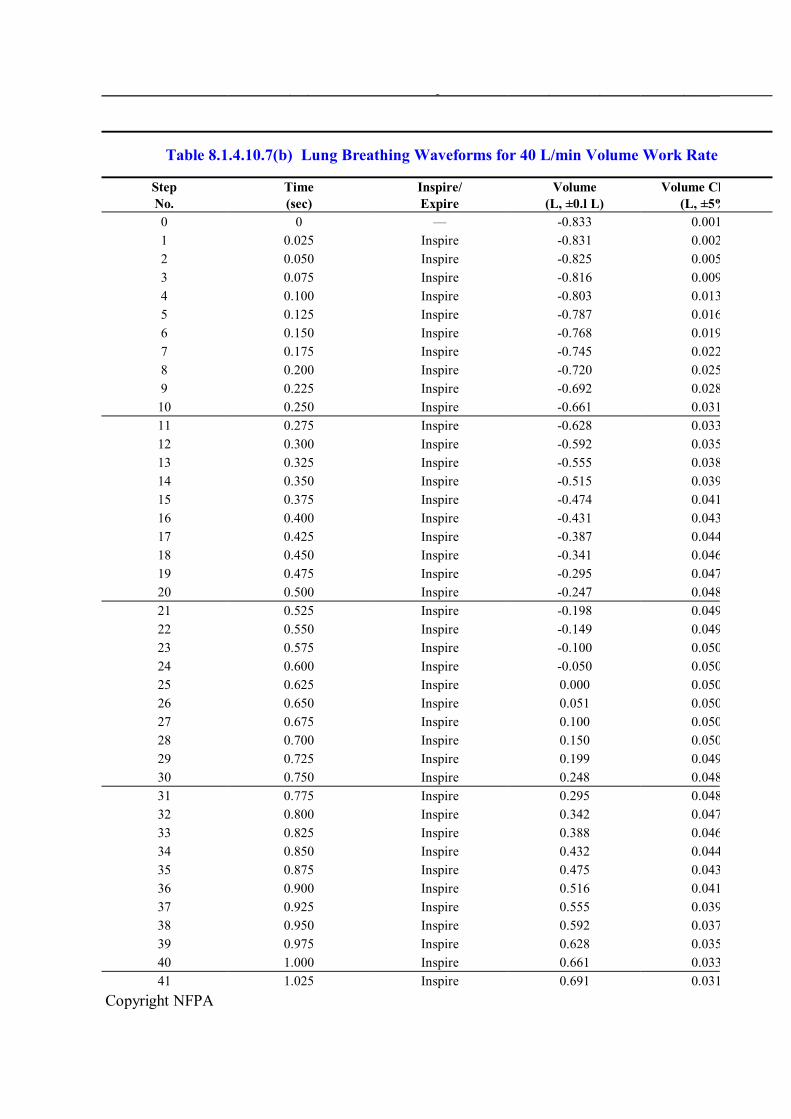
Copyright NFPA
No. (sec) Expire (L, ±0.l L) (L, ±5%)
Table 8.1.4.10.7(b) Lung Breathing Waveforms for 40 L/min Volume Work Rate
Step No.
Time (sec)
Inspire/ Expire
Volume (L, ±0.l L)
Volume Change (L, ±5%)
0 0 — 0.833 0.001 1 0.025 Inspire 0.831 0.002 2 0.050 Inspire 0.825 0.005 3 0.075 Inspire 0.816 0.009 4 0.100 Inspire 0.803 0.013 5 0.125 Inspire 0.787 0.016 6 0.150 Inspire 0.768 0.019 7 0.175 Inspire 0.745 0.022 8 0.200 Inspire 0.720 0.025 9 0.225 Inspire 0.692 0.028 10 0.250 Inspire 0.661 0.031 11 0.275 Inspire 0.628 0.033 12 0.300 Inspire 0.592 0.035 13 0.325 Inspire 0.555 0.038 14 0.350 Inspire 0.515 0.039 15 0.375 Inspire 0.474 0.041 16 0.400 Inspire 0.431 0.043 17 0.425 Inspire 0.387 0.044 18 0.450 Inspire 0.341 0.046 19 0.475 Inspire 0.295 0.047 20 0.500 Inspire 0.247 0.048 21 0.525 Inspire 0.198 0.049 22 0.550 Inspire 0.149 0.049 23 0.575 Inspire 0.100 0.050 24 0.600 Inspire 0.050 0.050 25 0.625 Inspire 0.000 0.050 26 0.650 Inspire 0.051 0.050 27 0.675 Inspire 0.100 0.050 28 0.700 Inspire 0.150 0.050 29 0.725 Inspire 0.199 0.049 30 0.750 Inspire 0.248 0.048 31 0.775 Inspire 0.295 0.048 32 0.800 Inspire 0.342 0.047 33 0.825 Inspire 0.388 0.046 34 0.850 Inspire 0.432 0.044 35 0.875 Inspire 0.475 0.043 36 0.900 Inspire 0.516 0.041 37 0.925 Inspire 0.555 0.039 38 0.950 Inspire 0.592 0.037 39 0.975 Inspire 0.628 0.035 40 1.000 Inspire 0.661 0.033 41 1.025 Inspire 0.691 0.031

Copyright NFPA
Table 8.1.4.10.7(b) Lung Breathing Waveforms for 40 L/min Volume Work Rate
Step No.
Time (sec)
Inspire/ Expire
Volume (L, ±0.l L)
Volume Change (L, ±5%)
42 1.050 Inspire 0.719 0.028 43 1.075 Inspire 0.744 0.025 44 1.100 Inspire 0.767 0.022 45 1.125 Inspire 0.786 0.019 46 1.150 Inspire 0.802 0.016 47 1.175 Inspire 0.814 0.013 48 1.200 Inspire 0.823 0.009 49 1.225 Inspire 0.829 0.005 50 1.250 — 0.833 0.004 51 1.275 Expire 0.831 0.002 52 1.300 Expire 0.825 0.005 53 1.325 Expire 0.816 0.009 54 1.350 Expire 0.803 0.013 55 1.375 Expire 0.787 0.016 56 1.400 Expire 0.768 0.019 57 1.425 Expire 0.745 0.022 58 1.450 Expire 0.720 0.025 59 1.475 Expire 0.692 0.028 60 1.500 Expire 0.661 0.031 61 1.525 Expire 0.628 0.033 62 1.550 Expire 0.592 0.035 63 1.575 Expire 0.555 0.038 64 1.600 Expire 0.515 0.039 65 1.625 Expire 0.474 0.041 66 1.650 Expire 0.431 0.043 67 1.675 Expire 0.387 0.044 68 1.700 Expire 0.341 0.046 69 1.725 Expire 0.295 0.047 70 1.750 Expire 0.247 0.048 71 1.775 Expire 0.198 0.049 72 1.800 Expire 0.149 0.049 73 1.825 Expire 0.100 0.050 74 1.850 Expire 0.050 0.050 75 1.875 Expire 0.000 0.050 76 1.900 Expire 0.051 0.050 77 1.925 Expire 0.100 0.050 78 1.950 Expire 0.150 0.050 79 1.975 Expire 0.199 0.049 80 2.000 Expire 0.248 0.048 81 2.025 Expire 0.295 0.048 82 2.050 Expire 0.342 0.047 83 2.075 Expire 0.388 0.046 84 2.100 Expire 0.432 0.044 85 2.125 Expire 0.475 0.043

Copyright NFPA
Table 8.1.4.10.7(b) Lung Breathing Waveforms for 40 L/min Volume Work Rate
Step No.
Time (sec)
Inspire/ Expire
Volume (L, ±0.l L)
Volume Change (L, ±5%)
86 2.150 Expire 0.516 0.041 87 2.175 Expire 0.555 0.039 88 2.200 Expire 0.592 0.037 89 2.225 Expire 0.628 0.035 90 2.250 Expire 0.661 0.033 91 2.275 Expire 0.691 0.031 92 2.300 Expire 0.719 0.028 93 2.325 Expire 0.744 0.025 94 2.350 Expire 0.767 0.022 95 2.375 Expire 0.786 0.019 96 2.400 Expire 0.802 0.016 97 2.425 Expire 0.814 0.013 98 2.450 Expire 0.823 0.009 99 2.475 Expire 0.829 0.005
8.1.4.10.8 Switching between the two work rates shall be performed within 10 seconds.
8.1.4.10.9 The construction of the breathing machine shall be such that the respiration rate, tidal volume, peak flow, and facepiece pressure measurement system accuracy are unaffected by temperature changes caused by the environmental airflow performance tests as specified in Section 8.2, Environmental Temperature Tests.
8.1.5 Procedure.
8.1.5.1* The test setup for conducting the airflow performance test shall be calibrated at least once each day before tests are conducted and shall be verified at least once each day after testing.
8.1.5.1.1 The calibration procedure utilized for the differential pressure transducer shall consist of confirmation of at least three different pressures between 0 mm and 125 mm (0 in. and 5 in.) water column.
8.1.5.1.2 The pressure shall be measured using an incline manometer or equivalent with a scale measuring in increments of ±0.5 mm (±0.02 in.) water column or less.
8.1.5.2 The SCBA being tested shall utilize a fully charged breathing air cylinder.
8.1.5.3 The facepiece of the SCBA being tested shall be secured to the test headform. The facepiece seal to the headform shall ensure that an initial pressure of 25 mm, ±2.5 mm (1 in., ±0.1 in.) water column below ambient shall not decay by more than 5 mm (0.2 in.) water column in 5 seconds.
8.1.5.4 The remaining components of the SCBA shall be mounted to simulate the proper wearing position as specified by the manufacturer’s instructions.

Copyright NFPA
8.1.5.5 SCBA shall be tested at an ambient temperature of 22°C, ±3°C (72°F, ±5°F) and RH of 50 percent, ±25 percent.
8.1.5.6 The airflow performance test shall begin after five cycles of the breathing machine and shall continue to operate through at least 20 bar (290 psi) of cylinder inlet pressure.
8.1.5.7 The breathing machine shall be set at a rate of 103 L/min, ±3 L/min with a respiratory frequency of 30 breaths/min, ±1 breath/min.
8.1.6 Report.
8.1.6.1 The facepiece peak inhalation pressure and peak exhalation pressure shall be recorded and reported for each test.
8.1.6.2 The EOSTI activation and operation or the failure of the EOSTI to activate and operate shall be recorded and reported.
8.1.6.3 The activation and identification of HUD visual alert signals shall be recorded and reported.
8.1.7 Interpretation.
8.1.7.1 The peak inhalation pressure and peak exhalation pressure shall be used to determine pass or fail performance.
8.1.7.2 One or more specimens failing this test shall constitute failing performance.
8.1.7.3 Failure of any EOSTI alarm signal to activate and remain active during the test shall constitute failing performance.
8.1.7.4 Failure of the HUD to display the breathing air cylinder content or to display the visual alert signal during the test shall constitute failing performance.
8.2 Environmental Temperature Tests.
8.2.1 Application. This test method shall apply to complete SCBA.
8.2.2 Samples. Each sample to be tested shall be as specified in 4.3.9.
8.2.3 Specimen Preparation.
8.2.3.1 Specimens for conditioning shall be complete SCBA.
8.2.3.2 Prior to testing, the SCBA shall be placed in an ambient environment of 22°C, ± 3°C (72°F, ±5°F) and RH of 50 percent, ±25 percent for a minimum 12hour dwell period.
8.2.4 Apparatus.
8.2.4.1 The SCBA shall be placed in an environmental chamber and positioned to simulate the normal wearing position of the SCBA on a person as specified by the manufacturer.
8.2.4.2 During the environmental exposures in 8.2.5.5, 8.2.5.6, 8.2.5.7, and 8.2.5.8, the SCBA shall be mounted on a Scott Aviation Model No. 80360801 or 80360802 test headform or equivalent.

Copyright NFPA
8.2.4.3 The thermocouple or other temperaturesensing element used shall be mounted within the chamber in a manner in which it will be exposed directly to the chamber atmosphere.
8.2.4.4 The test headform shall be connected to the breathing machine specified in Section 8.1, Airflow Performance Test.
8.2.4.5 The breathing machine shall be permitted to be located either inside or outside the environmental chamber.
8.2.5 Procedure.
8.2.5.1 The variation in pressure extremes caused by the environmental test configuration shall be determined in the following manner. The airflow performance test as specified in Section 8.1, Airflow Performance Test, shall be carried out using the configuration specified in 8.2.4 at the 103 L/min, ±3 L/min ventilation rate. The difference in pressure between the two tests shall be calculated by subtracting the values obtained using the configuration defined in 8.2.4 from the values obtained using the configuration specified in Section 8.1, Airflow Performance Test.
8.2.5.2 The facepiece pressure during each entire test shall be read from the strip chart recorder and corrected by adding the value of the difference in pressure calculated in 8.2.5.1 to determine pass or fail as specified in 7.2.1.1 through 7.2.1.4.
8.2.5.3 These environmental temperature tests shall be permitted to be conducted in any sequence.
8.2.5.4 The dwell period between environmental temperature tests shall be used for refilling the breathing air cylinder and visually inspecting the SCBA for any gross damage that could cause unsafe test conditions.
8.2.5.5 Test 1.
8.2.5.5.1 The SCBA shall be cold soaked at 32°C, ±1°C (25°F, ±2°F) for a minimum of 12 hours.
8.2.5.5.2 The SCBA shall then be tested for airflow performance as specified in Section 8.1, Airflow Performance Test, at a chamber air temperature of 32°C, ±5°C (25°F, ±10°F).
8.2.5.6 Test 2.
8.2.5.6.1 The SCBA shall be hot soaked at 71°C, ±1°C (160°F, ±2°F) for a minimum of 12 hours.
8.2.5.6.2 The SCBA shall then be tested for airflow performance as specified in Section 8.1, Airflow Performance Test, at a chamber air temperature of 71°C, ±5°C (160°F, ±10°F).
8.2.5.7 Test 3.
8.2.5.7.1 The SCBA shall be hot soaked at 71°C, ±1°C (160°F, ±2°F) for a minimum of 12 hours.
8.2.5.7.2 Immediately following the 12hour hot soak, the SCBA shall be transferred to a

Copyright NFPA
chamber with an air temperature of 32°C, ±1°C (25°F, ±2°F).
8.2.5.7.3 The SCBA shall then be tested for airflow performance as specified in Section 8.1, Airflow Performance Test, at a chamber air temperature of 32°C, ±5°C (25°F, ±10°F).
8.2.5.7.4 The airflow performance test shall commence within 3 minutes after removal of the SCBA from the hot soak.
8.2.5.8 Test 4.
8.2.5.8.1 The SCBA shall be cold soaked at 32°C, ±1°C (25°F, ±2°F) for a minimum of 12 hours.
8.2.5.8.2 Immediately following the 12hour cold soak, the SCBA shall be transferred to a chamber with an air temperature of 71°C, ±1°C (160°F, ±2°F).
8.2.5.8.3 The SCBA shall then be tested for airflow performance as specified in Section 8.1, Airflow Performance Test, at a chamber air temperature of 71°C, ±5°C (160°F, ±10°F).
8.2.5.8.4 The airflow performance test shall commence within 3 minutes after removal of the SCBA from the cold soak.
8.2.6 Report.
8.2.6.1 The facepiece peak inhalation pressure and peak exhalation pressure shall be recorded and reported for each test condition.
8.2.6.2 The activation and operation or the failure to activate and operate of the EOSTI shall be recorded and reported.
8.2.6.3 The activation and identification of HUD visual alert signals shall be recorded and reported.
8.2.7 Interpretation.
8.2.7.1 The peak inhalation and peak exhalation shall be used to determine pass or fail performance for each test procedure.
8.2.7.2 One or more specimens failing any test procedure shall constitute failing performance.
8.2.7.3 Failure of any EOSTI alarm signal to activate and remain active during the test shall constitute failing performance.
8.2.7.4 Failure of the HUD to display the breathing air cylinder content or to display the visual alert signal during the test shall constitute failing performance.
8.3 Vibration Test.
8.3.1 Application. This test method shall apply to complete SCBA.
8.3.2 Samples. Each sample to be tested shall be as specified in 4.3.9.
8.3.3 Specimen Preparation.

Copyright NFPA
8.3.3.1 Specimens for conditioning shall be complete SCBA.
8.3.3.2 Prior to testing, specimens shall be conditioned for a minimum of 4 hours and tested at an ambient temperature of 22°C, ±3°C (72°F, ±5°F) and RH of 50 percent, ±25 percent.
8.3.4 Apparatus.
8.3.4.1 SCBA shall be tested on a typical package tester within the compartments specified in 8.3.4.2 through 8.3.4.4.
8.3.4.2 Compartments shall be set up as specified in Figure 8.3.4.2(a) and Figure 8.3.4.2(b).
FIGURE 8.3.4.2(a) Vibration Table Compartments — Top View (Not to Scale).
FIGURE 8.3.4.2(b) Vibration Table Compartments — Side View (Not to Scale).
8.3.4.2.1 The sides and base of the compartments shall be constructed of nominal 6 mm (¼ in.) stainless steel, and the top of the compartments shall remain open.
8.3.4.2.2 There shall be no burrs, sharp edges, surface discontinuities, or fasteners on the internal surfaces of the holding boxes.
8.3.4.3 The large compartments shall encase the complete SCBA.
8.3.4.3.1 SCBA regulators and hose shall remain attached to the complete SCBA.
8.3.4.3.2 Regulators shall be allowed to be placed in the regulator holder of the SCBA.

Copyright NFPA
8.3.4.3.3 The SCBA facepiece and those components that attach directly to the facepiece, excluding regulators, shall not be included in the SCBA compartment.
8.3.4.4 The small compartments shall encase the facepiece and those components that attach directly to the facepiece, excluding the regulator and associated hose.
8.3.4.5* The breathing air cylinder of the SCBA shall be replaced by a surrogate cylinder.
8.3.4.6 The surrogate cylinder and cylinder valve shall be of identical design and construction as the breathing air cylinder and cylinder valve of the SCBA to be tested.
8.3.4.7 The mass of the breathing air of a fully pressurized breathing air cylinder shall be replaced in the surrogate cylinder with a substitute mass. The substitute mass shall consist of a brass rod and surrounding foam constructed as shown in Figure 8.3.4.7.
FIGURE 8.3.4.7 Surrogate Cylinder.
8.3.4.8 The surrogate cylinder and cylinder valve with the substitute mass shall have the same total mass ±5 percent as the fully pressurized breathing air cylinder and cylinder valve.
8.3.4.9 The attachment of the cylinder valve shall be tightened to a torque setting of 5 Nm, +0.5/0.0 5 Nm (45 in. lb, +5/0 in. lb) prior to the test. An opposing line no wider than 3 mm ( in.) shall be placed on both the male and female CGA fitting prior to the start of the test to identify the relationship between the male and the female CGA fittings when tightened

Copyright NFPA
at the proper torque setting.
8.3.5 Procedure.
8.3.5.1 The test items shall be placed unrestrained in the compartments specified in 8.3.4.2, and all SCBA adjustment straps shall be fully extended.
8.3.5.2 No tiedowns shall be allowed to be made to the SCBA.
8.3.5.3 The basic movement of the bed of the test table shall be a 25 mm (1 in.) orbital path, such as can be obtained on a standard package tester operating in synchronous mode at 250 rpm, ±5 rpm.
8.3.5.4 The test duration shall be 3 hours.
8.3.5.5 After being subjected to the vibration test, the male and female CGA fittings shall be observed for movement.
8.3.5.6 After being subjected to the vibration test, the SCBA shall be reattached to the breathing air cylinder originally provided with the SCBA and shall then be tested as specified in Section 8.1, Airflow Performance Test.
8.3.6 Report.
8.3.6.1 The observation of movement or no movement of the male and female CGA fittings shall be recorded and reported.
8.3.6.2 The facepiece peak inhalation pressure and peak exhalation pressure shall be recorded and reported for each test condition.
8.3.6.3 The activation and operation, or failure to activate and operate, of the EOSTI shall be recorded and reported.
8.3.6.4 The activation and identification of HUD visual alert signals shall be recorded and reported.
8.3.7 Interpretation.
8.3.7.1 The movement of either the male or female CGA fitting causing a break in the line of any width shall constitute a failure.
8.3.7.2 The peak inhalation and peak exhalation shall be used to determine pass or fail performance for each test procedure.
8.3.7.3 One or more specimens failing this test shall constitute failing performance.
8.3.7.4 Failure of any EOSTI alarm signal to activate and remain active during the test shall constitute failing performance.
8.3.7.5 Failure of the HUD to display the breathing air cylinder content or to display the visual alert signal during the test shall constitute failing performance.
8.4 Fabric Flame Tests.
8.4.1 Application.

Copyright NFPA
8.4.1.1 This test method shall apply to each different fabric component of the SCBA.
8.4.1.2 Modifications for testing fabrics less than 75 mm (3 in.) wide shall be as specified in 8.4.8.
8.4.1.3 Modifications for testing fabrics less than 305 mm (12 in.) long shall be as specified in 8.4.9.
8.4.2 Specimens.
8.4.2.1 Specimens shall consist of a 75 mm × 305 mm (3 in. × 12 in.) rectangle.
8.4.2.2 A total of 10 test specimens shall be cut from a standard production run of the fabric components used in the SCBA.
8.4.3 Specimen Preparation.
8.4.3.1 Five test specimens shall be tested without any conditioning.
8.4.3.2 The remaining five test specimens shall be conditioned by five cycles of washing and drying in accordance with the procedures specified in Machine Cycle 1, Wash Temperature V, Drying Procedure Ai, of AATCC 135, Dimensional Changes of Fabrics After Home Laundering.
8.4.4 Apparatus. The test apparatus specified in ASTM D 6413, Standard Test Method for Flame Resistance of Textiles (Vertical Test), shall be used.
8.4.5 Procedure.
8.4.5.1 Specimens shall be tested in accordance with ASTM D 6413, Standard Test Method for Flame Resistance of Textiles (Vertical Test).
8.4.5.2 Each specimen shall be examined for evidence of melting or ignition to determine pass or fail.
8.4.6 Report.
8.4.6.1 Afterflame time and char length shall be recorded and reported for each specimen.
8.4.6.2 The average afterflame time and char length for each material tested shall be calculated and reported.
8.4.6.3 The afterflame time shall be reported to the nearest 0.2 second and the char length to the nearest 3.2 mm ( in.).
8.4.6.4 Observations of melting or dripping for each specimen shall be reported.
8.4.7 Interpretation.
8.4.7.1 Pass or fail performance shall be based on any observed melting or dripping, the average afterflame time, and the average char length.
8.4.7.2 One or more specimens failing this test shall constitute failing performance.
8.4.8 Specific Requirements for Testing Fabrics Less Than 75 mm (3 in.) Wide.

Copyright NFPA
8.4.8.1 If the fabric components are not available in the width specified in 8.4.2.1, the width of the test specimen shall be the width as used on the SCBA, but shall be a minimum of 305 mm (12 in.) long.
8.4.8.2 The test frame in Figure 8.4.8.2 shall be utilized to hold samples not available in the width specified in 8.4.2.1.
FIGURE 8.4.8.2 Wire Lattice Test Frame.
8.4.8.3 Testing shall be performed as specified in 8.4.5.
8.4.9 Specific Requirements for Testing Fabrics Less Than 305 mm (12 in.) Long.
8.4.9.1 Where the fabric components are not available in the length specified in 8.4.2.1, the length of the test specimen shall be the length as used on the SCBA.
8.4.9.2 Samples that are not available in the length required in 8.4.2.1 shall be positioned such that the bottom edge of the sample is positioned at the bottom of the test frame.
8.4.9.3 Testing shall be performed as specified in 8.4.5.
8.5 Fabric Heat Tests.
8.5.1 Application.
8.5.1.1 This test method shall apply to each different fabric component of the SCBA.
8.5.1.2 Modifications for testing fabrics less than 380 mm (15 in.) wide shall be as specified in 8.5.8.
8.5.1.3 Modifications for testing fabrics less than 380 mm (15 in.) long shall be as specified

Copyright NFPA
in 8.5.9.
8.5.2 Specimens.
8.5.2.1 Specimens shall consist of a 380 mm × 380 mm (15 in. × 15 in.) square.
8.5.2.2 A total of 10 test specimens shall be cut from a standard production run of the fabric components used in the SCBA.
8.5.3 Specimen Preparation.
8.5.3.1 Five test specimens shall be tested without any conditioning.
8.5.3.2 The remaining five test specimens shall be conditioned by five cycles of washing and drying in accordance with the procedures specified in Machine Cycle 1, Wash Temperature V, Drying Procedure Ai, of AATCC 135, Dimensional Changes of Fabrics After Home Laundering.
8.5.4 Apparatus.
8.5.4.1 The test oven shall be a horizontal flow circulating oven with minimum interior dimensions so that the specimens can be suspended and are at least 50 mm (2 in.) from any interior oven surface and other test specimens.
8.5.4.2 The test oven shall have an airflow rate of 38 m/min to 76 m/min (125 ft/min to 250 ft/min) at the standard temperature and pressure of 21°C (70°F) at 1 atmosphere measured at the center point of the oven.
8.5.4.3 A test thermocouple shall be positioned so that it is level with the horizontal centerline of a mounted sample specimen.
8.5.4.3.1 The thermocouple shall be equidistant between the vertical centerline of a mounted specimen placed in the middle of the oven and the oven wall where the airflow enters the test chamber.
8.5.4.3.2 The thermocouple shall be an exposed bead, Type J or Type K, No. 30 AWG thermocouple.
8.5.4.3.3 The test oven shall be heated and the test thermocouple stabilized at 260°C, +6°C/0°C (500°F, +10°F/0°F) for a period of not less than 30 minutes.
8.5.5 Procedure.
8.5.5.1 The test specimen shall be suspended by a metal hook(s) at the top and centered in the oven so that the entire test specimen is at least 50 mm (2 in.) from any oven surface and other test specimens.
8.5.5.2 Oven airflow shall be parallel to the plane of the material.
8.5.5.3 The oven door shall not remain open more than 15 seconds.
8.5.5.3.1 The air circulation shall be shut off while the door is open and turned on when the door is closed.
8.5.5.3.2 The total oven recovery time after the door is closed shall not exceed 30 seconds.

Copyright NFPA
8.5.5.4 The specimen, mounted as specified, shall be exposed in the test oven for 5 minutes, +0.15 minute/0 minutes.
8.5.5.5 The test exposure time shall begin when the test thermocouple recovers to the temperature of 260°C, +6°C/0°C (500°F, +10°F/0°F).
8.5.5.6 Immediately after the specified exposure, the specimen shall be removed and examined for evidence of ignition or melting.
8.5.6 Report. Observations of ignition or melting shall be recorded and reported for each specimen.
8.5.7 Interpretation. Any evidence of ignition or melting on any specimen shall constitute failing performance.
8.5.8 Specific Requirements for Testing Fabrics Less Than 380 mm (15 in.) Wide.
8.5.8.1 If the fabric components are not available in the width specified in 8.5.2.1, the width of the test specimen shall be the width as used on the SCBA but shall be a minimum of 380 mm (15 in.) long.
8.5.8.2 Testing shall be performed as specified in 8.5.5.
8.5.9 Specific Requirements for Testing Fabrics Less Than 380 mm (15 in.) Long.
8.5.9.1 If the fabric components are not available in the length specified in 8.5.2.1, the length of the test specimen shall be the length as used on the SCBA.
8.5.9.2 Testing shall be performed as specified in 8.5.5.
8.6 Thread Heat Test.
8.6.1 Application . This test shall apply to sewing thread used in construction of the SCBA.
8.6.2 Specimens. Three 3 mg to 4 mg specimens shall be tested.
8.6.3 Specimen Preparation. Specimens shall be conditioned at 22°C, ±3°C (72°F, ±5°F) and RH of 50 percent, ±25 percent for a minimum of 4 hours prior to testing.
8.6.4 Apparatus.
8.6.4.1 An electrically heated stage having a circular depression large enough to insert a micro cover glass and a variable transformer controlling the rate of heat input to the stage shall be used.
8.6.4.2 Two armored stem thermometers shall be used, one with a range of 20°C to 160°C (68°F to 320°F), accurate to 0.5°C (1°F) and one with a range from 150°C to 300°C (302°F to 572°F), accurate to 1°C (2°F).
8.6.4.3 The following items shall be provided for test equipment:
(1) Low powered magnifying glass
(2) Two micro cover glasses

Copyright NFPA
(3) Spatula, pick needle, or other instrument for applying pressure to the cover glass
(4) Soxhlet extraction apparatus
(5) Chloroform, U.S.P. reagent
8.6.5 Procedure.
8.6.5.1 Specimens shall be extracted with chloroform for a minimum of 20 extractions in a Soxhlet extractor, or equivalent, and dried.
8.6.5.2 The specimen shall then be cut into lengths of 2 mm ( in.) or less.
8.6.5.3 The specimen shall be placed in a small mound on a cover glass and covered with another cover glass.
8.6.5.4 The two cover glasses shall be pressed together gently but firmly and placed in the circular depression on the stage.
8.6.5.5 The temperature of the stage shall be raised with some rapidity to 245°C (473°F) and thereafter at a rate of 3°C to 4°C (5°F to 8°F) per minute until 260°C (500°F) is reached.
8.6.5.6 At this rate of temperature rise, a slight pressure shall be applied on the upper glass cover by pressing with a spatula, pick needle, or other instrument, so that the complete fiber is in contact with the cover glass.
8.6.5.7 The specimen shall be observed with the aid of a magnifying glass at 260°C (500°F).
8.6.6 Report. Observations of any melting of the specimens shall be recorded and reported.
8.6.7 Interpretation. Any specimen exhibiting melting at 260°C (500°F) shall constitute failure of this test.
8.7 Accelerated Corrosion Test.
8.7.1 Application. This test method shall apply to complete SCBA.
8.7.2 Samples. Each sample to be tested shall be as specified in 4.3.9.
8.7.3 Specimen Preparation.
8.7.3.1 Prior to testing, specimens shall be conditioned for a minimum of 4 hours and tested at an ambient temperature of 22°C, ±3°C (72°F, ±5°F) and RH of 50 percent, ±25 percent.
8.7.3.2 Specimens for conditioning shall be complete SCBA.
8.7.4 Apparatus. A salt fog chamber shall be used for testing and shall meet the requirements of Section 4 of ASTM B 117, Standard Test Method for Salt Spray (Fog) Testing.
8.7.5 Procedure.
8.7.5.1 The SCBA with a fully charged breathing air cylinder, with the breathing air cylinder valve fully closed, shall be placed in the test chamber attached to a mannequin to simulate its

Copyright NFPA
typical wearing position on a fire fighter as specified by the manufacturer.
8.7.5.2 SCBA shall not contact each other or the sides of the test chamber.
8.7.5.3 The SCBA shall be placed in the temperaturestabilized chamber for a minimum of 2 hours prior to introduction of the salt solution.
8.7.5.4 The SCBA shall then be exposed to the salt fog for 48 hours, +15 minutes/0 minutes.
8.7.5.5 Specimen SCBA shall be subjected to a 5 percent, ±1 percent salt solution fog.
8.7.5.5.1 The salt solution shall be prepared by dissolving 5 parts, ±1 part by mass of sodium chloride in 95 parts of water.
8.7.5.5.2 The salt used shall be sodium chloride substantially free of nickel and copper and containing on the dry basis not more than 0.1 percent of sodium iodide and not more than 0.3 percent of total impurities.
8.7.5.5.3 The pH of the salt solution shall be in the range of 6.5 to 7.2.
8.7.5.6 The compressed air supply to the nozzle or nozzles for atomizing the salt solution shall be free of oil and dirt and maintained between 69 kPa/m and 172 kPa/m (10 psi and 25 psi).
8.7.5.7 The exposure temperature in the chamber shall be maintained at 35°C, ±1°C (95°F, ±2°F) for the duration of the test.
8.7.5.8 At least two clean fog collectors shall be placed within the exposure zone so that no drops of solution from the test specimens or any other source shall be collected in them.
8.7.5.8.1 The collectors shall be placed in the proximity of the test specimens, one nearest to any nozzle and the other farthest from all nozzles.
8.7.5.8.2 The fog shall be such that for each 80 cm 2 (12.4 in. 2 ) of horizontal collecting area from 1.0 mL to 2.0 mL of solution per hour will be collected in each collector.
8.7.5.9 After completion of the salt fog exposure, the SCBA shall be stored in an environment of 22°C, ±3°C (72°F, ±5°F) and RH of 50 percent, ±5 percent for a minimum of 48 hours.
8.7.5.10 The SCBA shall then be tested as specified in Section 8.1, Airflow Performance Test, to determine pass or fail.
8.7.5.11 All controls or operating features of the SCBA shall operate per the SCBA manufacturer’s instructions to determine pass or fail.
8.7.6 Report.
8.7.6.1 The facepiece pressure peak inhalation and peak exhalation shall be recorded and reported for each test condition.
8.7.6.2 The activation and operation, or failure to activate and operate, of the EOSTI shall be reported and recorded.
Copyright NFPA
8.7.6.3 The activation and identification of HUD visual alert signals shall be reported and recorded.
8.7.7 Interpretation.
8.7.7.1 The peak inhalation and peak exhalation shall be used to determine pass or fail performance.
8.7.7.2 One or more specimens failing this test shall constitute failing performance.
8.7.7.3 Failure of any EOSTI alarm signal to activate and remain active during the test shall constitute failing performance.
8.7.7.4 Failure of the HUD to display the breathing air cylinder content or to display the visual alert signal during the test shall constitute failing performance.
8.8 Particulate Test.
8.8.1 Application. This test method shall apply to complete SCBA.
8.8.2 Samples. Each sample to be tested shall be as specified in 4.3.9.
8.8.3 Specimen Preparation.
8.8.3.1 Prior to testing, specimens shall be conditioned for a minimum of 4 hours and tested at an ambient temperature of 22°C, ±3°C (72°F, ±5°F) and RH of 50 percent, ±25 percent.
8.8.3.2 Specimens for conditioning shall be complete SCBA.
8.8.4 Apparatus.
8.8.4.1 A Scott Aviation model No. 80360801 or 80360802 test headform or equivalent shall be joined to a mannequin to simulate its typical wearing position, as specified by the manufacturer.
8.8.4.2 The test headform shall be connected, as specified in Section 8.1, Airflow Performance Test, to the breathing machine specified in 8.1.4.9 or other respiration simulator producing a 1minute volume of 40 L, ±2 L at the ambient conditions specified in 8.1.3.2, with a minimum tidal volume of 1.6 L per breath at a minimum respiration of 10 breaths/min.
8.8.4.3 A test facility consisting of a chamber and accessories to control dust concentration, velocity, temperature, and humidity of dustladen air shall be used.
8.8.4.4 To provide adequate circulation of the dustladen air, no more than 50 percent of the crosssectional area and no more than 30 percent of the volume of the test chamber shall be occupied by the test item(s).
8.8.4.5* The chamber shall be provided with a means of maintaining and verifying the dust circulation.
8.8.4.6 The dustladen air shall be introduced into the test space in such a manner as to allow the air to become laminar in flow before it strikes the test item.
8.8.4.7* Dust shall be silica flour and shall contain 97 percent to 99 percent by weight

Copyright NFPA
silicon dioxide (SiO 2 ).
8.8.4.8 The following size distribution shall apply:
(1) 100 percent shall pass through a 100 mesh screen.
(2) 98 percent, ±2 percent shall pass through a 140 mesh screen.
(3) 90 percent, ±2 percent shall pass through a 200 mesh screen.
(4) 75 percent, ±2 percent shall pass through a 325 mesh screen.
8.8.5 Procedure.
8.8.5.1 A fully charged SCBA shall be secured to a test headform and mannequin as specified in 8.8.4.1.
8.8.5.2 The mannequin, including the test headform, shall be mounted upright and placed inside the test chamber.
8.8.5.3 The temperature of the test chamber shall be adjusted to 22°C, ±3°C (72°F, ±5°F) and the RH to less than 30 percent.
8.8.5.4 The air velocity shall be adjusted to 530 m/min, ±15 m/min (1750 ft/min, ±50 ft/min).
8.8.5.5 The dust concentration for the blowing dust shall be maintained at 10.6 g/m 3 , ±7 g/m 3 (0.3 g/ft 3 , ±0.2 g/ft 3 ).
8.8.5.6 The test duration shall be 1 hour, and the breathing machine shall be operating throughout the entire test.
8.8.5.6.1 The test shall be permitted to be interrupted to change the SCBA breathing air cylinder.
8.8.5.6.2 Test item configuration and orientation shall be turned around its vertical axis 180 degrees midway through the test.
8.8.5.7 After the completion of the test, the SCBA shall be removed from the test compartment.
8.8.5.8 The SCBA shall be lightly shaken or brushed free of dust and then shall be tested as specified in Section 8.1, Airflow Performance Test, to determine pass or fail.
8.8.6 Report.
8.8.6.1 The facepiece pressure peak inhalation and peak exhalation shall be recorded and reported for each test condition.
8.8.6.2 The activation and operation or failure to activate and operate of both EOSTI shall be recorded and reported.
8.8.6.3 The activation and identification of HUD visual alert signals shall be recorded and reported.
8.8.7 Interpretation.

Copyright NFPA
8.8.7.1 The peak inhalation and peak exhalation shall be used to determine pass or fail performance.
8.8.7.2 One or more specimens failing this test shall constitute failing performance.
8.8.7.3 Failure of any EOSTI alarm signal to activate and remain active during the test shall constitute failing performance.
8.8.7.4 Failure of the HUD to display the breathing air cylinder content or display the visual alert signal during the test shall constitute failing performance.
8.9 Facepiece Lens Abrasion Test.
8.9.1 Application. This test method shall apply to facepiece lenses.
8.9.2 Samples. A minimum of four faceshield lenses shall be tested.
8.9.3 Specimen Preparation.
8.9.3.1 Seven specimens shall be chosen from a minimum of four facepiece lenses.
8.9.3.1.1 Four specimens shall be taken from the left viewing area, and three samples shall be taken from the right viewing area.
8.9.3.1.2 One of the four specimens taken from the left viewing area shall be the setup specimen.
8.9.3.2 The left test specimens shall conform to all the following criteria:
(1) The specimen shall be a square measuring 50 mm × 50 mm (2 in. × 2 in.).
(2) Two edges of the square section shall be parallel within ± 2 degrees of the axis of the cylinder or cone in the center of the specimen.
(3) At least 38 mm (1½ in.) of the 50 mm × 50 mm (2 in. × 2 in.) square shall be taken from the left side of the center line of the lens.
(4) The 50 mm × 50 mm (2 in. × 2 in.) square shall be cut at approximately eye level.
8.9.3.3 The right test specimens shall conform to all the following criteria:
(1) The specimen shall be a square measuring 50 mm × 50 mm (2 in. × 2 in.).
(2) Two edges of the square section shall be parallel within ± 2 degrees of the axis of the cylinder or cone in the center of the specimen.
(3) At least 38 mm (1½ in.) of the 50 mm × 50 mm (2 in. × 2 in.) square shall be taken from the right side of the center line of the lens.
(4) The 50 mm × 50 mm (2 in. × 2 in.) square shall be cut at approximately eye level.
8.9.3.4 Each of the specimens shall be cleaned in the following manner:
(1) The specimen shall be rinsed with clean tap water.
(2) The specimen shall be washed with a solution of nonionic/lowphosphate detergent

Copyright NFPA
and water using a clean, soft gauze pad.
(3) The specimen shall be rinsed with deionized water.
(4) The specimen shall be blown dry with clean compressed air or nitrogen.
8.9.4 Apparatus. The test apparatus shall be constructed in accordance with Figure 8.9.4(a) and Figure 8.9.4(b).
FIGURE 8.9.4(a) Lens Abrasion Tester.

Copyright NFPA
FIGURE 8.9.4(b) Lens Abrasion Tester (details).
8.9.5 Procedure.
8.9.5.1 The haze of the specimen shall be measured using a haze meter in accordance with ASTM D 1003, Standard Test Method for Haze and Luminous Transmittance of Transparent Plastics, and recorded with the following additions:
(1) The haze shall be measured in the middle of the specimen ±1.6 mm (± in.).
(2) The specimen shall be repositioned to achieve the maximum haze value within the area defined in 8.9.5.1(1).
(3) The haze meter shall have a specified aperture of 22.4 mm ( in.).
(4) The haze meter shall have a visual display showing 0.1 percent resolution.
(5) The haze meter shall be calibrated before and after each day’s use following procedures specified in ASTM D 1003, Standard Test Method for Haze and Luminous Transmittance of Transparent Plastics.
8.9.5.2 The setup specimen shall be placed cover side up in the test apparatus specimen holder.

Copyright NFPA
8.9.5.3 The specimen holder shall be configured with a flat surface under the lens or with an inner radius support.
8.9.5.4 The pad holder shall consist of a cylinder 10 mm ( in.) high and 25 mm (1 in.) in diameter with a radius of curvature equal to the radius of curvature of the outside of the lens in the viewing area, ±0.25 diopter. This cylinder shall be rigidly affixed to the stroking arm by a #1032 UNF threaded rod.
8.9.5.5 The pad shall be a Blue Streak M306M wool felt polishing pad or equivalent, 24 mm ( in.) in diameter.
8.9.5.6 The abrasive disc shall be made from 3M Part Number 7415, Wood Finishing Pad or equivalent.
8.9.5.6.1 A disc 24 mm ( in.) in diameter shall be cut from the abrasive sheet.
8.9.5.6.2 The marked side of the disc shall be placed against the pad.
8.9.5.6.3 Care shall be exercised to maintain the orientation described in 8.9.5.6.2 for each abrasive disc throughout the testing.
8.9.5.7 The pad holder, pad, and abrasive disc shall be installed on the stroking arm.
8.9.5.7.1 The stroking arm shall be leveled to ±3 degrees by adjusting the threaded pin.
8.9.5.7.2 The pin shall be secured to prevent rotation of the pad holder.
8.9.5.7.3 The axis of curvature of the pad holder shall be coincident with the axis of curvature of the lens.
8.9.5.8 The stroking arm shall be counterbalanced with the pad holder, pad, and abrasive disc in place.
8.9.5.9 The setup specimen shall be replaced with one of the six specimens to be tested.
8.9.5.10 The 1000 g, ±5 g (2.2 lb, ±0.18 lb) test weight shall be installed on the pin above the test specimen.
8.9.5.11 The test shall be run for 200 cycles, ±1 cycle. One cycle shall consist of a complete revolution of the eccentric wheel.
8.9.5.12 The length of stroke shall be 14.5 mm ( in.), producing a pattern 38 mm (1½ in.) long.
8.9.5.12.1 The frequency of the stroke shall be 60 cycles, ±1 cycle, per minute.
8.9.5.12.2 The center of the stroke shall be within ±2 mm (± in.) of the center of the specimen.
8.9.5.13 The specimen shall be removed and cleaned following the procedure specified in 8.9.3.4.
8.9.5.14 The abrasive disc shall be discarded.

Copyright NFPA
8.9.5.15 The haze of the specimen shall be measured following the procedure specified in 8.9.5.1.
8.9.5.16 The delta haze shall be calculated by subtracting the initial haze from the final haze.
8.9.5.17 The testing steps specified in 8.9.3.4 through 8.9.5.16 shall be repeated five times with a new specimen and abrasive disc.
8.9.6 Report.
8.9.6.1 The six delta haze values shall be recorded, and the values shall be averaged and reported.
8.9.6.2 The average value shall be used to determine pass or fail.
8.9.7 Interpretation.
8.9.7.1 The average delta haze shall be used to determine pass or fail performance.
8.9.7.2 Failure of the average value shall constitute failure for the entire sample.
8.10 Mechanical Voice Diaphragm Test.
8.10.1 Application. This test method shall apply to complete SCBA.
8.10.2 Samples. Each sample to be tested shall be as specified in 4.3.9 with voice communications systems installed and in the “off” mode per manufacturer instructions.
8.10.3 Specimen Preparation.
8.10.3.1 Prior to testing, specimens shall be conditioned for a minimum of 4 hours and tested at an ambient temperature of 22°C, ±3°C (72°F, ±5°F) and RH of 50 percent, ±25 percent.
8.10.3.2 Specimens for conditioning shall be complete SCBA.
8.10.4 Apparatus.
8.10.4.1 Testing shall be conducted in a chamber that absorbs a minimum of 90 percent of all sound from 500 Hz to 5000 Hz.
8.10.4.2 Five listening subjects and five talkers consisting of four males and one female shall be available for testing. The alternative of electronic recording of five talkers for testing automation and repeatability shall be permitted.
8.10.4.3 The subjects participating as listeners shall have “audiometrically normal” hearing as defined in Section 5.3 of ANSI S3.2, Method for Measuring the Intelligibility of Speech over Communication Systems, in the range of 500 Hz to 3000 Hz and shall not be permitted to use any device that would enhance their ability to hear.
8.10.4.4 Talkers and listeners shall be selected and trained according to Section 7 of ANSI S3.2, Method for Measuring the Intelligibility of Speech over Communication Systems.
8.10.4.5 The five talkers shall not have facial hair, any unusual facial characteristics, or any other condition that could cause interference with the seal of the facepiece.

Copyright NFPA
8.10.4.6 The talkers shall perform and pass a qualitative facepiecetoface fit check per the SCBA manufacturer’s instructions.
8.10.4.7 Where the talker is qualified to wear several sizes of facepieces, the talker shall choose the facepiece that is most comfortable.
8.10.4.8 The five talkers shall be trained in the donning and usage of the SCBA per manufacturer’s instructions.
8.10.4.9 The five talkers shall have no obvious speech defect or strong regional accent.
8.10.4.10 The distance between the talker and the listener(s) shall be 1.5 m, +305 mm/0 mm (5 ft, +1 ft/0 ft), and they shall be facing each other.
8.10.4.11 The test chamber shall be filled with broadband “pink” noise with a tolerance of 6 dB per octave band from 400 Hz to 4000 Hz.
8.10.4.12 The forward axis of the loudspeaker shall be oriented away from the listener group.
8.10.4.13 The distance between the loudspeaker and the listeners shall be as great as possible so as to create a quasiuniform sound field over the listening group.
8.10.4.14 More than one loudspeaker shall be permitted to be used to achieve the desired sound field.
8.10.4.15 The gain of the power amplifier used to generate the pink noise shall be adjusted to achieve an Aweighted sound level of 70 dB, ±2 dB, at each listener’s head position, without listeners present.
8.10.5 Procedure.
8.10.5.1 The method for measuring word intelligibility shall be as specified in ANSI S3.2, Method for Measuring the Intelligibility of Speech over Communication Systems, with the modified apparatus specified in 8.10.4.
8.10.5.2 The test material shall be the reading of one complete list of modified rhyme words as contained in Table 2 of ANSI S3.2, Method for Measuring the Intelligibility of Speech over Communication Systems.
8.10.5.2.1 The words shall be spoken singularly in the following carrier sentence: “Would you circle [list word] now?”
8.10.5.2.2 The rate shall be approximately one test word every 6 seconds.
8.10.5.2.3 The talkers shall be trained to talk at 75 dBA to 85 dBa without an SCBA facepiece, measured at the listener’s ear, placing no unusual stress on any word.
8.10.5.2.4 Training shall include the use of background noise as defined in 8.10.4.11 through 8.10.4.15.
8.10.5.2.5 The talkers shall not vary their voice level from that used without the facepiece after the facepiece is donned.

Copyright NFPA
8.10.5.2.6 The listeners shall circle each word as they hear it.
8.10.5.3 The talkers shall conduct two tests in the chamber having an ambient noise field as specified in 8.10.4.11 through 8.10.4.15, using a different word list for each of the following conditions:
(1) With no SCBA
(2) With SCBA worn and operated per the SCBA manufacturer’s instructions
8.10.5.4 Talkers’ speech shall be monitored during the tests to determine if the talkers conform to the word list specified for that test.
8.10.5.5 Each listener’s response form shall be scored as to the number of correct responses out of the 50 words recited.
8.10.5.5.1 Listeners’ scores shall be based on the words actually spoken by the talkers.
8.10.5.5.2 Listeners’ scores shall not be reduced because of speaking mistakes of the talkers.
8.10.5.5.3 All of the listeners’ scores without the SCBA used by the talker shall be averaged, and all of the listeners’ scores with the SCBA used by the talker shall be averaged.
8.10.5.5.4 The average score of the five listeners for the talker using the SCBA shall be divided by the average score of the five listeners for the talker without using the SCBA, and the result shall be called the “score value.” This procedure shall be performed for each of the five talkers.
8.10.5.6 The average of the score values obtained in 8.10.5.5.3 and 8.10.5.5.4 shall be calculated.
8.10.5.6.1 Where the average of the score values is 80 percent, this average score value shall be used to determine pass or fail.
8.10.5.6.2 Where the average of the score values is <80 percent, the sample standard deviation (s.d.) of the score values shall be calculated in the following manner:
where:
x = score values N = sample size (5)
8.10.5.6.3 Where the calculated sample standard deviation of the test score values is 10.0, the test shall be invalidated and the procedures of 8.10.5.2 through 8.10.5.6.6 shall be repeated.
8.10.5.6.4 Where the calculated sample standard deviation of the test score values is <10.0, a test statistic, Tvalue, shall be calculated to determine if the average of the score values

Copyright NFPA
obtained is or is not equivalent to 80 percent. The Tvalue shall be calculated in the following manner:
where:
= 72 percent = average of the score values
N = sample size (5) s.d. = sample standard deviation
8.10.5.6.5 For Tvalues 2.13, the score value shall be considered 80 percent and shall be used to determine pass or fail.
8.10.5.6.6 For Tvalues >2.13, the score value shall be as calculated in 8.10.5.6, and this calculated score value shall be used to determine pass or fail performance.
8.10.6 Report. The average of the score values obtained shall be calculated, recorded, and reported.
8.10.7 Interpretation. The average of the score values shall be used to determine pass or fail performance.
8.11* Heat and Flame Test.
8.11.1 Application. This test method shall apply to complete SCBA.
8.11.2 Samples. Each sample to be tested shall be as specified in 4.3.9.
8.11.3 Specimen Preparation.
8.11.3.1 Prior to testing, specimens shall be conditioned for a minimum of 4 hours and tested at an ambient temperature of 22°C, ±3°C (72°F, ±5°F) and RH of 50 percent, ±25 percent.
8.11.3.2 Specimens for conditioning shall be complete SCBA.
8.11.4 Apparatus.
8.11.4.1 A test mannequin meeting the requirements specified in Figure 8.11.4.1 shall be provided.

Copyright NFPA
FIGURE 8.11.4.1 Test Mannequin.
8.11.4.2 Both the calibration mannequin and the heat and flame test mannequin shall have protective coverings.
8.11.4.2.1 The protective coverings shall be a weld blanket made of fireproof silica cloth of a minimum weight of 18 oz/sq yd.
8.11.4.2.2 The protective coverings shall be designed and constructed to provide coverage over the surface of the mannequins.
8.11.4.2.3 Where additional insulation is needed to protect the mannequin electronics, an additional thermal liner underlayer shall be permitted.
8.11.4.2.4 The complete protective covering shall be discarded and shall not be used where the damage to any portion indicates the covering can no longer provide thermal protection for the test mannequin.
8.11.4.3 A test headform meeting the requirements specified in 8.1.4.1 shall be used on the test mannequin.
8.11.4.4 The test headform shall be attached to the breathing machine as specified in Figure

Copyright NFPA
8.1.4.9, with the modification that a 38 mm (1½ in.) I.D. breathing hose, not longer than 7.6 m (25 ft), shall be interconnected between the breathing machine and the throat tube of the test mannequin headform.
8.11.4.5 The test headform shall be covered with an undyed aramid hood for protection of the headform during testing.
8.11.4.5.1 The protective hood shall meet the hood requirements of NFPA 1971, Standard on Protective Ensembles for Structural Fire Fighting and Proximity Fire Fighting.
8.11.4.5.2 The protective hood, when placed on the test headform, shall not affect the seal of the facepiece to the headform.
8.11.4.5.3 The protective hood shall not cover or protect any part of the facepiece or the facepiece retention system that holds the facepiece to the headform.
8.11.4.6 The heat and flame test apparatus shall be as specified in Figure 8.11.4.6.

Copyright NFPA
FIGURE 8.11.4.6 Heat and Flame Test Apparatus.
8.11.4.6.1 The test oven shall be a horizontal forced circulating air oven with a range of flow of 38 m/min to 76 m/min (125 ft/min to 250 ft/min).
8.11.4.6.2 The test oven shall have minimum dimensions of 915 mm depth × 915 mm width × 1.22 m height (36 in. depth × 36 in. width × 48 in. height).
8.11.5 Procedure.
8.11.5.1 The SCBA shall be mounted on the test mannequin to simulate the correct wearing position on a person as specified by the SCBA manufacturer’s instructions.
8.11.5.2 The facepiece shall be mounted and tested on the test headform as specified in 8.1.4.1.
8.11.5.3 For calibration prior to the heat and flame test, the mannequin for calibration shall be the same as the test mannequin specified in 8.11.4.1 and shall be exposed to direct flame contact for 10 seconds using the heat and flame test apparatus.
8.11.5.3.1 All peak temperature readings shall be within a temperature range of 815°C to 1150°C (1500°F to 2102°F).
8.11.5.3.2 The average mean of all peak temperature readings specified in 8.11.5.3.1 shall be no higher than 950°C (1742°F).
8.11.5.4 The test oven recovery time, after the door is closed, shall not exceed 1.0 minute.
8.11.5.5 The airflow performance test shall be conducted as specified in 8.1.5, with modifications to the ventilation rate specified in 8.11.5.7 with the test temperatures specified in 8.11.5.3 and 8.11.5.8.
8.11.5.5.1 The variation in pressure extremes caused by the heat and flame test mannequin configuration shall be determined as specified in 8.11.5.5.2 and 8.11.5.5.3.
8.11.5.5.2 The airflow performance test as specified in Section 8.1, Airflow Performance Test, shall be carried out using the configuration specified in 8.11.4.4 at the same ventilation rates.
8.11.5.5.3 The difference in pressure between the two tests shall be calculated by subtracting the values obtained using the configuration defined in 8.11.4.4 from the values obtained using the configuration specified in Section 8.1, Airflow Performance Test.
8.11.5.6 The airflow performance test shall continue through the drop test specified in 8.11.5.15.
8.11.5.7 The ventilation rate shall be set at 40 L/min, ±2 L/min, with a respiratory frequency of 12 breaths/min, ±1 breath/min at ambient conditions as specified in 8.1.3.2.
8.11.5.8 The SCBA mounted on the test mannequin shall be placed in the test oven that has been preheated to 95°C, ±2°C (203°F, ±4°F).
8.11.5.9 After the test oven door is closed and the oven temperature recovers to 95°C
Copyright NFPA
(203°F), the test exposure time of 15 minutes shall begin.
8.11.5.10 At the completion of the 15minute exposure, the ventilation rate shall be increased to 103 L/min, ±3 L/min, as specified in 8.1.4.10.7.
8.11.5.11 The oven door shall be opened, and the SCBA mounted on the test mannequin shall be moved out of the oven and into the center of the burner array.
8.11.5.12 The SCBA shall then be exposed to direct flame contact for 10 seconds, +0.25 second/0.0 seconds.
8.11.5.13 This exposure shall begin within 20 seconds of removal of the SCBA from the test oven.
8.11.5.14 The SCBA shall be observed for any afterflame, and the afterflame duration shall be recorded to determine pass or fail as specified in 7.11.2.
8.11.5.15 Within 20 seconds after the direct flame exposure has been completed, the SCBA mounted on the test mannequin shall be raised 150 mm, +6 mm/0 mm (6 in., +¼ in./0 in.) and dropped freely.
8.11.5.16 The SCBA shall be observed to determine pass or fail performance as specified in 7.11.3.
8.11.5.17 The facepiece pressure during the entire test shall be read from the strip chart recorder and corrected by adding the value of the difference in pressure calculated in 8.11.5.5.1 to determine pass or fail as specified in 7.11.1.
8.11.5.18 Any pressure spike caused by the impact of the drop test and measured within a duration of three cycles of the breathing machine after the apparatus drop shall be disregarded.
8.11.5.19 The SCBA facepiece and HUD shall be removed from the test headform and shall be donned by a test subject without touching the facepiece lens or HUD.
8.11.5.19.1 The test subject shall have visual acuity of 20/20 in each eye, uncorrected or corrected with contact lenses.
8.11.5.19.2 The test subject shall then observe the HUD display to see that visual alert signal(s) have activated.
8.11.5.19.3 The test subject shall identify the visual alert signals that are activated.
8.11.5.20 The SCBA facepiece, removed from the test headform and donned by the test subject as specified in 8.11.5.19, shall be used for determining facepiece lens vision.
8.11.5.20.1 The test shall be conducted using a standard 6.1 m (20 ft) eye chart with normal lighting range of 120 to 150 ftcandles at the chart and with the test subject positioned at a distance of 6.1 m (20 ft) from the chart.
8.11.5.20.2 The test subject shall then read the standard eye chart at some point through the nominal center of the lens of the facepiece to determine pass or fail performance as specified in 7.11.4.

Copyright NFPA
8.11.5.20.3 The nominal center of the lens shall be the area bounded by a line 50 mm (2 in.) above, 50 mm (2 in.) below, 50 mm (2 in.) left, and 50 mm (2 in.) right of the intersection of the basic and midsagittal planes.
8.11.5.21 The activation of the EOSTI shall be observed.
8.11.6 Report.
8.11.6.1 The facepiece pressure peak inhalation and peak exhalation shall be recorded and reported for each test condition.
8.11.6.2 Any afterflame beyond 2.2 seconds shall be recorded and reported.
8.11.6.3 The facepiece lens vision shall also be recorded and reported.
8.11.6.4 The activation and operation or failure to activate and operate of EOSTI shall be recorded and reported.
8.11.6.5 The activation and identification of HUD visual alert signals shall be recorded and reported.
8.11.7 Interpretation.
8.11.7.1 Pass or fail performance shall be based on any observed afterflame, the peak inhalation and exhalation values, and the facepiece vision value.
8.11.7.2 Failure to meet any of the test condition requirements shall constitute failure of the SCBA.
8.11.7.3 Failure of any EOSTI alarm signals to activate and remain active during the test shall constitute failing performance.
8.11.7.4 Failure of the HUD to display the breathing air cylinder content or to display the visual alert signals during the test shall constitute failing performance.
8.12 Facepiece Carbon Dioxide Content Test.
8.12.1 Application. This test shall apply to all SCBA facepieces.
8.12.2 Specimens. Each SCBA facepiece model and size shall be tested.
8.12.3 Specimen Preparation. Prior to testing, specimens shall be conditioned for a minimum of 4 hours and tested at an ambient temperature of 22°C, ±3°C (72°F, ±5°F) and RH of 50 percent, ±25 percent.
8.12.4 Procedure. Specimens shall be tested as specified in Section 8.14 of EN 136, Respiratory protective devices — Full face masks — Requirements, testing, marking.
8.12.5 Report. The facepiece carbon dioxide content shall be recorded and reported for each test specimen.
8.12.6 Interpretation.
8.12.6.1 The facepiece carbon dioxide content shall be used to determine pass or fail performance.

Copyright NFPA
8.12.6.2 One or more specimens failing this test shall constitute failing performance.
8.13 EOSTI Independent Activation Test.
8.13.1 Application. This test method shall apply to complete SCBA.
8.13.2 Samples. Samples for testing shall be selected as specified in 4.3.9.
8.13.3 Specimen Preparation. Prior to testing, specimens shall be conditioned for a minimum of 4 hours at an ambient temperature of 22°C, ±3°C (72°F, ±5°F) and RH of 50 percent, ±25 percent.
8.13.4 Apparatus.
8.13.4.1 Testing shall be performed using a calibrated pressure gauge accurate to within ±0.25 percent of full span and graduated in increments of 0.5 bar (7.5 psi) or smaller.
8.13.4.2 A bleed valve capable of bleeding pressure at a rate not exceeding 50 bar (750 psi) per minute shall be used.
8.13.4.3 An adapter shall be provided to connect the calibrated pressure gauge and bleed valve to the SCBA breathing air cylinder connection.
8.13.5 Procedure.
8.13.5.1 Each SCBA test specimen shall be modified so that all EOSTI sensing mechanisms, other than the one being tested, are blocked to simulate failure.
8.13.5.2 SCBA test specimens shall be tested at an ambient temperature of 22°C, ±3°C (72°F, ±5°F) and RH of 50 percent, ±25 percent.
8.13.5.3 The adapter to connect the calibrated pressure gauge and bleed valve shall be installed at the breathing air cylinder connection on the SCBA test specimen.
8.13.5.4 After pressurizing the SCBA test specimen breathing air cylinder to greater than 30 percent of cylinder rated service pressure, the pressure shall be bled to ambient pressure at a rate not greater than 50 bar (750 psi) per minute.
8.13.5.5 The EOSTI alarm signal from the unblocked EOSTI shall function as specified in 7.13.1.
8.13.5.6 This test shall be repeated for each EOSTI.
8.13.6 Report.
8.13.6.1 The activation of the EOSTI alarm signal and the breathing air cylinder pressure at which the alarm signal activates shall be recorded and reported.
8.13.6.2 The breathing air cylinder pressure at which the EOSTI alarm signal stops shall be recorded and reported.
8.13.6.3 The proper functioning of the EOSTI alarm signal as specified in 7.13.1 shall be recorded and reported.
8.13.7 Interpretation.
Copyright NFPA
8.13.7.1 The proper activation and continued operation to the specified pressure shall be used to determine pass or fail performance.
8.13.7.2 One or more specimens failing this test shall constitute failing performance.
8.14 EOSTI Recognition Test.
8.14.1 Application. This test method shall apply to complete SCBA.
8.14.2 Samples. Samples for testing shall be selected as specified in 4.3.9.
8.14.3 Specimen Preparation. Prior to testing, specimens shall be conditioned for a minimum of 4 hours at an ambient temperature of 22°C, ±3°C (72°F, ±5°F) and RH of 50 percent, ±25 percent.
8.14.4 Apparatus.
8.14.4.1 An adapter shall be provided that allows the person conducting the test to manually switch between a breathing air supply greater than 30 percent of the SCBA breathing air cylinder rated service pressure and a breathing air supply pressure of 18 bar, ±1 bar (265 psi, ±15 psi).
8.14.4.2 Each SCBA test specimen shall be tested separately by two individual test subjects.
8.14.4.3 Test subjects shall wear full structural firefighting protective ensemble, including coat, trousers, helmet, hood, gloves, and footwear, that is certified as compliant with NFPA 1971, Standard on Protective Ensembles for Structural Fire Fighting and Proximity Fire Fighting.
8.14.4.4 Testing shall be performed with test subjects walking at 5 km/hr, ±0.2 km/hr (3 mph, ±0.12 mph) on a treadmill at zero percent grade.
8.14.4.5 Testing shall be conducted in a test chamber that absorbs a minimum of 90 percent of all sound from 500 Hz to 5000 Hz.
8.14.4.6 Test subjects shall have “audiometrically normal” hearing as defined in Section 5.3 of ANSI S3.2, Method for Measuring the Intelligibility of Speech over Communication Systems, in the range of 500 Hz to 3000 Hz.
8.14.4.7 Test subjects shall have had a physical examination conducted by a physician within the past 12 months of the date of testing.
8.14.4.8 The treadmill shall be positioned in the test chamber specified in 8.14.4.5 in a location where the conditions for background noise, lighting, and distraction specified in 8.14.4.9 and 8.14.4.10 are met.
8.14.4.9 The test chamber shall be filled with “pink” noise with a tolerance of 6 dB per octave band from 400 Hz to 4000 Hz and shall be adjusted to achieve an Aweighted sound level of 75 dB, ±2 dB measured at each ear of the test subject when the subject is walking on the treadmill as specified in 8.14.4.4.
8.14.4.9.1 The forward axis of the loudspeaker shall be located as far as possible from and pointed away from the test subject so as to create a quasiuniform sound field at the test

Copyright NFPA
subject’s ears.
8.14.4.9.2 More than one loudspeaker shall be permitted to be used to achieve the desired sound level.
8.14.4.10 The area in the test chamber where the test subject’s head is positioned when the subject is standing in the walking location on the treadmill shall be artificially lighted to achieve a light level between 100 lux and 500 lux.
8.14.4.11 A reading stand containing printed text shall be positioned relative to the treadmill as follows:
(1) The vertical center of the text shall be in line with the center of the treadmill track within ±100 mm (±4 in.).
(2) The horizontal center of the text shall be at the same height, ±100 mm (±4 in.), as the eye level of the test subject when the subject is standing in the walking position on the treadmill.
(3) The text shall be at a distance from the test subject that permits the text to be read by the subject while the subject is walking on the treadmill.
8.14.5 Procedure.
8.14.5.1* Each specimen to be tested shall be an SCBA modified such that all EOSTI sensing mechanisms other than the one being tested are blocked so as to simulate failure.
8.14.5.2 Prior to testing, the special adapter specified in 8.14.4.1 shall be installed at the breathing air cylinder connection on the SCBA specimen and the cylinder replaced with the air source specified in 8.14.4.1.
8.14.5.3 Each SCBA test specimen shall be modified so that all EOSTI sensing mechanisms, other than the one being tested, are blocked to simulate failure.
8.14.5.4 SCBA test specimens shall be tested at an ambient temperature of 22°C, ±3°C (72°F, ±5°F) and RH of 50 percent, ±25 percent.
8.14.5.5 A test subject wearing the protective ensemble specified in 8.14.4.3 shall don the test specimen SCBA and begin walking on the treadmill in the ambient conditions specified in 8.14.4.9 and 8.14.4.10.
8.14.5.6 While breathing from the SCBA, the test subject shall read aloud the printed text.
8.14.5.7 The person conducting the testing shall switch from the breathing air supply at greater than 30 percent of cylinder rated service pressure to 18 bar, ±1 bar (265 psi, ±15 psi) at a random point between 30 seconds and 120 seconds from the commencement of the test.
8.14.5.8 The test subject shall acknowledge recognition of the alarm signal immediately upon becoming aware of it by a gesture that has been predetermined between the test subject and the person performing the testing.
8.14.5.9 The test shall be repeated by the second test subject.
8.14.6 Report. The time elapsed between the switch to low supply air pressure and the

Copyright NFPA
acknowledgement of recognition of the EOSTI alarm signal by the test subject shall be recorded and reported.
8.14.7 Interpretation. Failure of either of the two test subjects to acknowledge recognition of the EOSTI alarm signal within the time period specified in 7.13.2 shall constitute failing performance.
8.15 HUD Wiring Connection Strength Test.
8.15.1 Application. This test method shall apply to SCBA facepieces with HUD and any associated assemblies with interconnecting wiring.
8.15.2 Samples. Each sample to be tested shall be as specified in 4.3.9.
8.15.3 Specimen Preparation.
8.15.3.1 Specimens for conditioning shall be SCBA facepieces with HUD and any associated assemblies with interconnecting wiring.
8.15.3.2 Prior to testing, specimens shall be conditioned for a minimum of 4 hours and tested at an ambient temperature of 22°C, ±3°C (72°F, ±5°F) and RH of 50 percent, ±25 percent.
8.15.4 Apparatus. A mass of known weight with the means for attachment to wiring shall be provided.
8.15.5 Procedure. A force of 156 N, ±9 N (35 lbf, ±2 lbf) shall be applied gradually, in an axial direction, to the wiring of the specimen being tested.
8.15.6 Report. Observations of the HUD functionality shall be recorded and reported.
8.15.7 Interpretation. Observation of HUD functionality in accordance with 6.3.5 shall be used to determine pass or fail performance.
8.16 HUD Low Power Source Visual Alert Signal Test.
8.16.1 Application. This test shall apply to all HUD low power source visual alert signals.
8.16.2 Samples. Each sample to be tested shall be as specified in 4.3.9.
8.16.3 Specimen Preparation. Specimens shall be conditioned for a minimum of 4 hours and tested at an ambient temperature of 22°C, ±3°C (72°F, ±5°F) and RH of 50 percent, ±25 percent.
8.16.4 Apparatus. A variable power source that is capable of supplying dc voltage of at least 30 percent more than the nominal power source voltage shall be provided.
8.16.5 Procedure.
8.16.5.1 Each HUD shall be tested with a variable power source to determine that the low power source visual alert signal will activate at the voltage, ±3 percent, that is specified by the manufacturer.
8.16.5.2 Each HUD shall be tested with a variable power source to determine that the HUD
Copyright NFPA
will continue to display the visual information and visual alert signals down to the ceaseproperoperation voltage, ±3 percent, that is specified by the manufacturer.
8.16.5.3 Each HUD power source shall be tested by discharging it at the nominal operating current specified by the manufacturer until the voltage falls to the level at which the HUD low power source visual alert signal illuminates as specified in 6.3.8.6.
8.16.5.4 Upon reaching that voltage, the current drain shall be increased to the peak current drain of the power source specified by the manufacturer for all systems supplied by that power source. Under these conditions and for a period of at least 2 hours, the power source voltage shall remain above the voltage that would cause the HUD to cease proper operation.
8.16.6 Report.
8.16.6.1 HUD shall be observed for activation of the low power source visual alert signal.
8.16.6.2 HUD shall be observed for the display of the visual information and visual alert signals down to the ceaseproperoperation voltage.
8.16.6.3 The power source voltage shall be observed with respect to the ceaseproperoperation voltage.
8.16.6.4 The events in 8.16.6.1 through 8.16.6.3 shall be recorded and reported.
8.16.7 Interpretation.
8.16.7.1 HUD low power source visual alert signal function shall be evaluated to determine pass or fail performance.
8.16.7.2 HUD power source voltage greater than or equal to the ceaseproperoperation voltage shall constitute pass.
8.17 HUD Visibility Test.
8.17.1 Darkness Test.
8.17.1.1 Application. This test method shall apply to complete SCBA.
8.17.1.2 Samples. Each sample to be tested shall be as specified in 4.3.9.
8.17.1.3 Specimen Preparation. Prior to testing, specimens shall be conditioned for a minimum of 4 hours and tested at an ambient temperature of 22°C, ±3°C (72°F, ±5°F) and RH of 50 percent, ±25 percent.
8.17.1.4 Apparatus.
8.17.1.4.1 The SCBA breathing air cylinder shall be permitted to be replaced with a cylinder of lesser capacity. The breathing air capacity of the replacement cylinder shall be greater than 200 L (7.1 ft 3 ).
8.17.1.4.2 Testing shall be performed in a lightcontrolled enclosure designated as the “testing enclosure.” A diffusedlight source that provides a luminance of 2 lux, ±1 lux shall be used to illuminate across the surface of the SCBA facepiece lens.

Copyright NFPA
8.17.1.5 Procedure.
8.17.1.5.1 The selected test subjects shall have visual acuity of 20/20 in each eye uncorrected or corrected with contact lenses. Selected test subjects shall be able to read lowercase letters measuring 2.5 mm ( in.) in height at a distance of 305 mm (12 in.).
8.17.1.5.2 The test subject shall don a complete SCBA.
8.17.1.5.3 The test subject shall enter the testing enclosure and be positioned so that the SCBA facepiece is illuminated as specified in 8.17.1.4.2.
8.17.1.5.4 The test subject shall wait 1 minute to allow the eyes to acclimate to the illumination.
8.17.1.5.5 The SCBA shall be activated so as to activate the HUD.
8.17.1.5.6 The cylinder shall be fully charged, and the HUD shall show full cylinder charge.
8.17.1.5.7 The SCBA pressure shall be slowly decreased so as to activate all HUD visual displays.
8.17.1.6 Report.
8.17.1.6.1 Each visual display of information and each visual alert signal as defined by the manufacturer’s instructions shall be observed for distinctness and identifiability.
8.17.1.6.2 The test subject’s observations of distinctness and identifiability shall be recorded and reported.
8.17.1.7 Interpretation.
8.17.1.7.1 The test subject’s ability to distinguish between each visual display of information and each visual alert signal as defined by the manufacturer’s instructions shall be observed, and the distinguishing features shall be distinct and identifiable.
8.17.1.7.2 Failure of the test subject to be able to observe each visual display of information and each visual alert signal as distinct, identifiable, or both shall constitute failing performance.
8.17.2 Light Test.
8.17.2.1 Application. This test method shall apply to complete SCBA.
8.17.2.2 Samples. Each sample to be tested shall be as specified in 4.3.9.
8.17.2.3 Specimen Preparation. Prior to testing, specimens shall be conditioned for a minimum of 4 hours and tested at an ambient temperature of 22°C, ±3°C (72°F, ±5°F) and RH of 50 percent, ±25 percent.
8.17.2.4 Apparatus.
8.17.2.4.1 The SCBA breathing air cylinder shall be permitted to be replaced with a cylinder of lesser capacity. The breathing air capacity of the replacement cylinder shall be greater than 200 L (7.1 ft 3 ).

Copyright NFPA
8.17.2.4.2 Testing shall be performed in a lightcontrolled enclosure designated as the “testing enclosure.” A diffused light source that provides a luminance of 10,000 lux, ±1000 lux shall be used to illuminate across the surface of the SCBA facepiece lens.
8.17.2.5 Procedure.
8.17.2.5.1 The selected test subjects shall have visual acuity of 20/20 in each eye uncorrected or corrected with contact lenses. Selected test subjects shall be able to read lowercase letters measuring 2.5 mm ( in.) in height at a distance of 305 mm (12 in.).
8.17.2.5.2 The test subject shall don a complete SCBA.
8.17.2.5.3 The test subject shall enter the testing enclosure and be positioned so that the SCBA facepiece is illuminated as specified in 8.17.2.4.2.
8.17.2.5.4 The test subject shall wait 1 minute to allow the eyes to acclimate to the illumination.
8.17.2.5.5 The SCBA shall be activated so as to activate the HUD.
8.17.2.5.6 The cylinder shall be fully charged, and the HUD shall show full cylinder charge.
8.17.2.5.7 The SCBA pressure shall be slowly decreased so as to activate all HUD visual displays.
8.17.2.6 Report.
8.17.2.6.1 Each visual display of information and each visual alert signal as defined by the manufacturer’s instructions shall be observed and shall be distinct and identifiable.
8.17.2.6.2 The test subject’s observations shall be recorded and reported.
8.17.2.7 Interpretation. The test subject’s ability to distinguish among the visual displays of information and the visual alert signals as defined by the manufacturer’s instructions shall be observed, and distinguishing features shall be distinct and identifiable.
8.18 HUD Obscuration Test.
8.18.1 Application. This test method shall apply to complete SCBA where there is a gap greater than 1 mm ( in.) between the HUD and the exterior surface of the SCBA facepiece lens.
8.18.2 Samples. Each sample to be tested shall be as specified in 4.3.9.
8.18.3 Specimen Preparation. Prior to testing, specimens shall be conditioned for a minimum of 4 hours and tested at an ambient temperature of 22°C, 3°C (72°F, ±5°F) and RH of 50 percent, ±25 percent.
8.18.4 Apparatus.
8.18.4.1 Each test specimen to be tested shall be an SCBA with the facepiece modified by the application of a lightreducing film to the entire outer lens surface of the facepiece. The film shall exclude 94.5 percent to 95.5 percent of visible light.

Copyright NFPA
8.18.4.2 The SCBA breathing air cylinder shall be permitted to be replaced with a cylinder of lesser capacity. The breathing air capacity of the replacement cylinder shall be greater than 200 L (7.1 ft 3 ).
8.18.4.3 Testing shall be performed in a lightcontrolled enclosure designated as the “testing enclosure.” A diffuse light source that provides a luminance of 20 lux, +0/5 lux shall be used to illuminate across the surface of the SCBA facepiece lens.
8.18.5 Procedure.
8.18.5.1 The selected test subjects shall have visual acuity of 20/20 in each eye uncorrected or corrected with contact lenses.
8.18.5.2 The test subject shall don a complete SCBA.
8.18.5.3 The test subject shall enter the testing enclosure and be positioned so that the SCBA facepiece is illuminated as specified in 8.18.4.3.
8.18.5.4 The test subject shall wait at least 1 minute to allow the eyes to acclimate to the illumination.
8.18.5.5 The SCBA shall be activated so as to activate the HUD.
8.18.5.6 The SCBA pressure shall be slowly decreased until the breathing air supply in the cylinder is exhausted.
8.18.6 Report.
8.18.6.1 The test subject shall report which informational displays and visual alert signals were observed.
8.18.6.2 The test subject’s observations shall be recorded and reported.
8.18.7 Interpretation. The test subject’s observations shall be compared to the manufacturer’s specified informational displays and visual alert signals to determine pass or fail performance.
8.19 HUD Disabling Glare Test.
8.19.1 Application. This test method shall apply to complete SCBA.
8.19.2 Samples. Each sample to be tested shall be as specified in 4.3.9.
8.19.3 Specimen Preparation. Prior to testing, test specimens shall be conditioned for a minimum of 4 hours and tested at an ambient temperature of 22°C, ±3°C (72°F, ±5°F) and RH of 50 percent, ±25 percent.
8.19.4 Apparatus.
8.19.4.1 Testing shall be performed in a lightcontrolled enclosure designated as the “testing enclosure,” with a diffused light source that provides a luminance of 2 lux, +0/–1 lux measured at the surface of the reading text card.
8.19.4.2 At least eight text cards for reading shall be provided. Each text card shall have 10

Copyright NFPA
different randomly selected letters of 2.5 mm ( in.) in height printed in lowercase on the card.
8.19.4.3 The SCBA breathing air cylinder shall be permitted to be replaced with a cylinder of lesser capacity. The breathing air capacity of the replacement cylinder shall be greater than 200 L (7.1 ft 3 ).
8.19.5 Procedure.
8.19.5.1 The selected test subjects shall have visual acuity of 20/20 in each eye uncorrected or corrected with contact lenses. Selected test subjects shall be able to read lowercase letters measuring 2.5 mm ( in.) in height at a distance of 305 mm (12 in.).
8.19.5.2 The test subject shall enter the testing enclosure that is illuminated as specified in 8.19.4.1.
8.19.5.3 The test subject shall wait at least 1 minute to allow the eyes to acclimate to the illumination.
8.19.5.4 A text card as specified in 8.19.4.2 shall be used for each beforereading procedure and each afterreading procedure of a single test.
8.19.5.5 Different text cards as specified in 8.19.4.2 shall be used for each test.
8.19.5.6 With the test subject’s vision blocked, the text card shall be placed in a fixed position inside the testing enclosure at a distance of 305 mm, +0/25 mm (12 in., +0/1 in.) from the test subject’s face.
8.19.5.7 For the beforereading portion of the test procedure, the test subject shall read out loud the 10 letters on the text card.
8.19.5.8 The test subject shall then don a complete SCBA.
8.19.5.9 The SCBA shall be activated so as to activate the HUD.
8.19.5.10 With the test subject’s vision blocked, a different text card shall be placed in a fixed position inside the testing enclosure at a distance of 305 mm, +0/25 mm (12 in., +0/1 in.) from the test subject’s SCBA facepiece lens.
8.19.5.11 The SCBA cylinder pressure shall then be slowly decreased until the breathing air supply in the cylinder is exhausted.
8.19.5.12 The afterreading portion of the test procedure shall be conducted while the cylinder pressure is being slowly decreased. The test subject shall read out loud the 10 letters on the text card.
8.19.6 Report.
8.19.6.1 The test subject’s visual acuity as required in 8.19.5.1 shall be recorded and reported.
8.19.6.2 The test subject’s ability to read the lowercase letters as required in 8.19.5.1 shall be recorded and reported.

Copyright NFPA
8.19.6.3 The test subject’s reading of the 10 letters in the beforereading portion of the test as required in 8.19.5.7 shall be recorded and reported for each letter.
8.19.6.4 The test subject’s reading of the 10 letters in the afterreading portion of the test as required in 8.19.5.12 shall be recorded and reported for each letter.
8.19.7 Interpretation.
8.19.7.1 The test subject’s inability to read at least 9 of the 10 beforereading letters shall constitute failing performance.
8.19.7.2 The test subject’s inability to read at least 9 of the 10 afterreading letters shall constitute failing performance.
8.20 Cylinder Refill Breathing Performance Test.
8.20.1 Application. This test method shall apply to complete SCBA.
8.20.2 Samples. Each sample to be tested shall be as specified in 4.3.9.
8.20.3 Specimen Preparation. Prior to testing, test specimens shall be conditioned for a minimum of 4 hours at an ambient temperature of 22°C, ±3°C (72°F, ±5°F) and RH of 50 percent, ±25 percent.
8.20.4 Apparatus.
8.20.4.1 The test apparatus shall be as specified in 8.1.4.
8.20.4.2 An RIC UAC filling hose assembly shall be provided.
8.20.4.3 The breathing air source shall provide a constant pressure equal to the rated service pressure of the SCBA breathing air cylinder, +0/6.8 bar (+0/100 psi).
8.20.5 Procedure.
8.20.5.1 The SCBA shall be tested for airflow performance as specified in 8.1.5, with the modification that the test will begin with the SCBA breathing air cylinder pressurized to 25 percent of the rated pressure.
8.20.5.2 The RIC UAC filling hose shall be connected to the constant pressure source.
8.20.5.3 At 10 cycles, ±5 cycles of the breathing machine, the RIC UAC female fitting on the RIC filling hose shall be connected to the RIC UAC male fitting on the SCBA. The RIC UAC coupling shall remain connected until the air transfer is completed.
8.20.5.4 The duration of the airflow performance test shall end 4 minutes after the air transfer has commenced per 8.20.5.3.
8.20.6 Report. The facepiece peak inhalation and exhalation pressure shall be recorded and reported.
8.20.7 Interpretation. The peak inhalation and peak exhalation pressures shall be used to determine pass or fail performance.

Copyright NFPA
8.21 RIC UAC System Fill Rate Test.
8.21.1 Application. This test method shall apply to complete SCBA.
8.21.2 Samples. Each sample to be tested shall be as specified in 4.3.9.
8.21.3 Specimen Preparation. Prior to testing, the specimens shall be conditioned for a minimum of 4 hours at an ambient temperature of 22°C, ± 3°C (72°F, ±5°F) and RH of 50 percent, ±25 percent.
8.21.4 Apparatus.
8.21.4.1 An RIC UAC filling hose assembly shall be provided.
8.21.4.2 The air source shall provide a constant pressure equal to the rated service pressure of the SCBA cylinder, +0/6.8 bar (+0/100 psi).
8.21.4.3 Testing shall be performed using a timer capable of measuring elapsed time within the range of 0 to 5 minutes.
8.21.5 Procedure.
8.21.5.1 The pressure of the SCBA breathing air cylinder shall be 0 bar (0 psi).
8.21.5.2 The RIC UAC filling hose shall be connected to the constant pressure air source.
8.21.5.3 With the SCBA breathing air cylinder valve fully open, the RIC UAC filling hose shall be connected to the RIC UAC male fitting.
8.21.5.4 The test timer shall begin when the RIC UAC filling hose is connected to the SCBA.
8.21.5.5 The pressure in the SCBA breathing air cylinder shall be monitored.
8.21.5.6 When the pressure in the SCBA breathing air cylinder reaches 75 percent of the rated service pressure of the SCBA cylinder, the test timer shall be stopped.
8.21.6 Report. The elapsed time shall be observed, recorded, and reported.
8.21.7 Interpretation. The elapsed fill time shall be used to determine pass or fail.
8.22 Breathing Air Cylinder and Valve Assembly Retention Test.
8.22.1 Application. This test method shall apply to complete SCBA assemblies.
8.22.2 Samples.
8.22.2.1 Samples shall be complete SCBA.
8.22.2.2 Samples shall be fitted with each of the SCBA manufacturer's breathing air cylinder and valve assemblies.
8.22.3 Specimen Preparation.
8.22.3.1 One SCBA sample shall be tested with a cylinder and valve assembly as specified in 8.22.5.

Copyright NFPA
8.22.3.2 Prior to testing, specimens shall be conditioned for a minimum of 4 hours at an ambient temperature of 22°C, ±3°C (72°F, ±5°F), with RH of 50 percent, ±25 percent.
8.22.4 Apparatus.
8.22.4.1 A test bench or similar fixture that can firmly fix a fully assembled SCBA to the test bench or fixture and that will not allow movement of the SCBA shall be used.
8.22.4.2 Measurements shall be taken with a calibrated measuring device having a resolution of better than ±0.25 mm (±0.010 in.).
8.22.4.3 Loops, straps, or pads shall be positioned on the valve to facilitate the application and measurement of an applied load to the intersection of the valve connection plane with the center line of the breathing air cylinder body.
8.22.5 Procedure.
8.22.5.1 The specimen, fitted with the SCBA manufacturer's breathing air cylinder and valve assembly, shall be fixed to the backplate and harness assembly in accordance with the manufacturer’s end user instructions provided with the SCBA.
8.22.5.2 The fully assembled SCBA shall be firmly fixed to the test bench or fixture in a manner that prevents movement of the SCBA but shall not interfere with the breathing air cylinder and valve assembly retention method.
8.22.5.3 The distances for each of the six directions specified in 8.22.5.4, the original starting positions, shall be measured and recorded.
8.22.5.4 A force of 200 N (45 lbf) shall be applied to the intersection point specified in 8.22.4.3, in the six directions shown in Figure 8.22.5.4. The force shall be applied for a period of 10 seconds, +5/0 seconds, allowing the measurements to be taken.
FIGURE 8.22.5.4 Directions of Force Applied for Retention Testing.
8.22.5.5 Following the application of force for each direction, the distance for each of the six directions shall be measured and recorded.
8.22.6 Report.

Copyright NFPA
8.22.6.1 The distance moved from the original starting position for each of the six directions shall be recorded and reported.
8.22.6.2 No portion of the breathing air cylinder and valve assembly shall show movement greater than 25 mm (1 in.) from its original position prior to load application.
8.22.7 Interpretation. Movement of any part of the breathing air cylinder and valve assembly that exceeds 25 mm (1 in.) shall constitute failing performance.
8.23 Cylinder Connections and Accessibility Test.
8.23.1 Application. This test method shall apply to complete SCBA assemblies.
8.23.2 Samples.
8.23.2.1 Samples shall be complete SCBA.
8.23.2.2 Samples shall be fitted with each of the SCBA manufacturer's air cylinder and valve assemblies.
8.23.3 Specimen Preparation.
8.23.3.1 The SCBA manufacturer's cylinder and valve assembly shall be fixed to the backplate harness assembly following the manufacturer’s end user instructions.
8.23.3.2 Prior to testing, specimens shall be conditioned for a minimum of 4 hours at an ambient temperature of 22°C, ±3°C (72°F, ±5°F), with RH of 50 percent, ±25 percent.
8.23.4 Procedure.
8.23.4.1 The specimen, fitted with each of the SCBA manufacturer's cylinder and valve assemblies, shall be fixed to the backplate and harness assembly in accordance with the manufacturer’s end user instructions provided with the SCBA.
8.23.4.2 Specimens shall be evaluated for accessibility, attachment, and detachment by a test subject with a hand that is categorized as large, and the test subject shall perform the test while wearing a size large structural fire fighting glove that is compliant with NFPA 1971, Standard on Protective Ensembles for Structural Fire Fighting and Proximity Fire Fighting.
8.23.4.3 The test subject shall fully attach the cylinder and valve assembly to the SCBA and then fully detach the cylinder and valve assembly from the SCBA. The time in seconds to attach and then to detach the cylinder and valve assembly shall be measured.
8.23.4.4 The test subject shall fully attach the breathing air fill hose to the RIC UAC connection and then fully detach the breathing air fill hose from the RIC UAC connection. The time in seconds to attach and then to detach the breathing air fill hose shall be measured.
8.23.5 Report.
8.23.5.1 The time to fully attach and to fully detach the cylinder and valve assemblies, timed in 8.23.4.3, shall be recorded and reported.
8.23.5.2 The time to fully attach and to fully detach the breathing air fill hose to and from

Copyright NFPA
the RIC UAC connection, timed in 8.23.4.4, shall be recorded and reported.
8.23.6 Interpretation.
8.23.6.1 One or more specimens failing the attachment and detachment times for the cylinder and valve assemblies shall constitute failing performance.
8.23.6.2 One or more specimens failing the attachment and detachment times for the RIC UAC connection shall constitute failing performance.
8.24 Heat and Immersion Leakage Tests.
8.24.1 Application. This test method shall apply to each electronic device of the SCBA required to meet the design requirements of Chapter 6.
8.24.2 Samples.
8.24.2.1 Each sample to be tested shall be as specified in 4.3.9.
8.24.2.2 Samples for conditioning shall be complete SCBA.
8.24.3 Specimens.
8.24.3.1 Prior to testing, specimens shall be conditioned for a minimum of 4 hours at an ambient temperature of 22°C, ±3°C (72°F, ±5°F) and RH of 50 percent, ±25 percent.
8.24.3.2 Two specimens shall be tested after conditioning within an oven specified in 8.24.4 at 177°C, +5°C/0°C (350°F, +10°F/0°F) for 15 minutes.
8.24.4 Apparatus.
8.24.4.1 The test oven shall have an airflow rate of 38 m/min to 76 m/min (125 ft/min to 250 ft/min) at the standard temperature and pressure of 21°C (70°F) at 1 atmosphere measured at the center point of the oven.
8.24.4.2 The test oven shall have minimum dimensions of 915 mm depth × 915 mm width × 1220 mm height (36 in. depth × 36 in. width × 48 in. height).
8.24.4.3 A test thermocouple shall be positioned so that it is level with the horizontal centerline of a mounted sample specimen.
8.24.4.4 The test water container shall be capable of covering the uppermost point of the specimen SCBA with a depth of 1.5 m (4.9 ft) of water.
8.24.4.5 The water temperature shall be 18°C, ±10°C (64°F, ±18°F).
8.24.5 Procedure.
8.24.5.1 The SCBA shall be mounted on the test mannequin and tested for a watertight seal per 8.1.5.3. It shall then be placed in the test oven that has been preheated to 177°C, +5°C/0°C (350°F, +10°F/0°F).
8.24.5.2 After the test oven door is closed and the oven temperature recovers to 177°C (350°F), the test exposure time of 15 minutes shall begin.
8.24.5.3 Within 2 minutes, the specimen, mounted to the mannequin, shall be immersed in

Copyright NFPA
the test water container for 15 minutes. After 15 minutes, the specimen shall be removed from the test water container and shall be wiped dry.
8.24.5.4 The specimen shall be subjected to 8.24.5.1 through 8.24.5.3 for six complete cycles.
8.24.5.5 The specimen shall be removed following the sixth conditioning cycle, and testing shall begin within 30 seconds of removal from conditioning.
8.24.5.6 On one of the two specimens, all electronic components shall be operated in accordance with the manufacturer's instructions for normal use to determine the proper functioning.
8.24.5.7 The specimen shall be reimmersed in the test water container for an additional 5 minutes. The power source compartment(s) shall be open, and the power source shall not be installed.
8.24.5.8 After the 5minute immersion, the specimen shall be removed from the test water container and shall be wiped dry.
8.24.5.9 The electronic compartment(s) of the specimen shall be opened and inspected for water leakage to determine pass or fail.
8.25 Voice Communications System Test.
8.25.1 Application. This test method shall apply to complete SCBA.
8.25.2 Samples. Each sample to be tested shall be as specified in 4.3.9.
8.25.3 Specimen Preparation.
8.25.3.1 Prior to testing, specimens shall be conditioned for a minimum of 4 hours and tested at an ambient temperature of 22°C, ±3°C (72°F, ±5°F) and RH of 50 percent, ±25 percent.
8.25.3.2 Specimens for conditioning shall be complete SCBA.
8.25.4 Apparatus.
8.25.4.1 Testing shall be conducted in a chamber that absorbs a minimum of 90 percent of all sound from 500 Hz to 5000 Hz.
8.25.4.2 Five listening subjects and five talkers consisting of four males and one female shall be available for testing. The alternative of electronic recording of five talkers for testing automation and repeatability shall be permitted.
8.25.4.3 The subjects participating as listeners shall have “audiometrically normal” hearing as defined in Section 5.3 of ANSI S3.2, Method for Measuring the Intelligibility of Speech over Communication Systems, in the range of 500 Hz to 3000 Hz, and shall not be permitted to use any device that would enhance their ability to hear.
8.25.4.4 Talkers and listeners shall be selected and trained according to Section 7 of ANSI S3.2, Method for Measuring the Intelligibility of Speech over Communication Systems.

Copyright NFPA
8.25.4.5 The five talkers shall not have facial hair, any unusual facial characteristics, or any other condition that could cause interference with the seal of the facepiece.
8.25.4.6 The talkers shall perform and pass a qualitative facepiecetoface fit check per the SCBA manufacturer’s instructions.
8.25.4.7 Where the talker is qualified to wear several sizes of facepieces, the talker shall choose the facepiece that is most comfortable.
8.25.4.8 The five talkers shall be trained in the donning and usage of the SCBA per manufacturer’s instructions.
8.25.4.9 The five talkers shall have no obvious speech defects or strong regional accents.
8.25.4.10 The distance between the talker and the listener(s) with the SCBA donned shall be 3 m, +305 mm/0 mm (10 ft, +1 ft/0 ft), and they shall be facing each other.
8.25.4.10.1 The distance between the talker and the listener(s) without the SCBA donned shall be 3 m, +305 mm/0 mm (10 ft, +1 ft/0 ft), and they shall be facing each other.
8.25.4.11 The test chamber shall be filled with broadband “pink” noise with a tolerance of 6 dB per octave band from 400 Hz to 4000 Hz.
8.25.4.12 The forward axis of the loudspeaker shall be oriented away from the listener group.
8.25.4.13 The distance between the loudspeaker and the listeners shall be as great as possible so as to create a quasiuniform sound field over the listening group.
8.25.4.14 More than one loudspeaker shall be permitted to be used to achieve the desired sound field.
8.25.4.15 The gain of the power amplifier used to generate the pink noise shall be adjusted to achieve an Aweighted sound level of 70 dB, ±2 dB at each listener’s head position, without the listeners present.
8.25.5 Procedure.
8.25.5.1 The method for measuring word intelligibility shall be as specified in ANSI S3.2, Method for Measuring the Intelligibility of Speech over Communication Systems, with the modified apparatus specified in 8.25.4.
8.25.5.2 Where the voice communications system is equipped with an adjustable volume (gain) control, the volume control shall be set at the lowest level during testing.
8.25.5.3 The test material shall be the reading of one complete list of modified rhyme words as contained in Table 2 of ANSI S3.2, Method for Measuring the Intelligibility of Speech over Communication Systems.
8.25.5.3.1 The words shall be spoken singularly in the following carrier sentence: “Would you circle [list word] now?”
8.25.5.3.2 The rate shall be approximately one test word every 6 seconds.

Copyright NFPA
8.25.5.3.3 The talkers shall be trained to talk at 75 dBA to 85 dBA without an SCBA facepiece, measured at 1.5 m, +305 mm/0 mm (5 ft, +1 ft/0 ft) distance at the height of the listener’s ear, placing no unusual stress on any word.
8.25.5.3.4 Training shall include the use of background noise as defined in 8.25.4.11 through 8.25.4.15.
8.25.5.3.5 The talkers shall not vary their voice levels from that used without the facepiece after the facepiece is donned.
8.25.5.3.6 The listeners shall circle each word as they hear it.
8.25.5.4 The talkers shall conduct two tests in the chamber having an ambient noise field as specified in 8.25.4.11 through 8.25.4.15, using a different word list for each of the following conditions:
(1) With no SCBA
(2) With SCBA worn and operated per the SCBA manufacturer’s instructions
8.25.5.5 The talkers’ speech shall be monitored during the tests to determine if the talkers conform to the word list specified for that test.
8.25.5.6 Each listener’s response form shall be scored as to the number of correct responses out of the 50 words recited.
8.25.5.6.1 Listeners’ scores shall be based on the words actually spoken by the talkers.
8.25.5.6.2 Listeners’ scores shall not be reduced because of speaking mistakes of the talkers.
8.25.5.6.3 All of the listeners’ scores without the SCBA used by the talker shall be averaged, and all of the listeners’ scores with the SCBA used by the talker shall be averaged.
8.25.5.6.4 The average score of the five listeners for the talker using the SCBA at a distance of 3 m, +305 mm/0 mm (10 ft, +1 ft/0 ft) shall be divided by the average score of the five listeners for the talker without using the SCBA at a distance of 1.5 m, +305 mm/0 mm (5 ft, +1 ft/0 ft), and the result shall be called the “score value.” This procedure shall be performed for each of the five talkers.
8.25.5.7 The average of the score values obtained in 8.25.5.6.3 and 8.25.5.6.4 shall be calculated.
8.25.5.7.1 Where the average of the score values is 85 percent, this average score value shall be used to determine pass or fail performance.
8.25.5.7.2 Where the average of the score values is <85 percent, the sample standard deviation (s.d.) of the score values shall be calculated in the following manner:

Copyright NFPA
where:
x = score values N = sample size (5)
8.25.5.7.3 Where the calculated sample standard deviation of the test score values is 10.0, the test shall be invalidated, and the procedures in 8.25.5.3 through 8.25.5.7.2 shall be repeated.
8.25.5.7.4 Where the calculated sample standard deviation of the test score values is <10.0, a test statistic, Tvalue, shall be calculated to determine if the average of the score values obtained is or is not equivalent to 85 percent:
where:
= 85 percent = average of the score values
N = sample size (5) s.d. = sample standard deviation
8.25.5.7.5 For Tvalues 2.13, the score value shall be considered to be equivalent to a score value of 85 percent.
8.25.5.7.6 For Tvalues >2.13, the score value shall be as calculated in 8.25.5.6, and this calculated score value shall be used to determine pass or fail.
8.25.6 Report. The average of the score values obtained shall be calculated, recorded, and reported.
8.25.7 Interpretation. The average of the score values shall be used to determine pass or fail.
8.26 Low Power Capacity Test.
8.26.1 Application. This test shall apply to all electronic devices required for SCBA by the requirements of Chapter 6.
8.26.2 Samples. Each sample to be tested shall be as specified in 4.3.9.
8.26.3 Specimen Preparation. Specimens shall be conditioned for a minimum of 4 hours and tested at an ambient temperature of 22°C, ±3°C (72°F, ±5°F) and RH of 50 percent, ±25 percent.
8.26.4 Apparatus. A variable power source that is capable of supplying dc voltage of at least 30 percent more than the nominal power source voltage shall be provided.
8.26.5 Procedure.
8.26.5.1 Each electronic device shall be tested with a variable power source to determine that the low power source visual alert signal will activate at the voltage specified by the

Copyright NFPA
manufacturer, ±3 percent.
8.26.5.2 Each electronic device shall be tested with a variable power source to determine that the electronic device will continue to operate down to the ceaseproperoperation voltage specified by the manufacturer.
8.26.5.3 Where multiple electronic devices that are part of the SCBA share a common power source, the minimum amount of power that causes the activation of the low power source visual alert signal shall be determined with all electronics sharing the common power source operating at their respective maximum power consumption under normal use.
8.26.5.3.1 Each electronic device power source shall be tested by discharging it at the cumulative nominal operating current for all electronic devices utilizing the power source, as specified by the manufacturer, until the voltage falls to the level at which the electronic device low power source visual alert signal illuminates as specified in 7.19, Low Power Capacity.
8.26.5.3.2 Upon reaching this voltage, the current drain shall be increased to the cumulative peak current drain of all electronic devices utilizing the power source, as specified by the manufacturer. Under these conditions and for a period of at least 2 hours, the power source voltage shall remain above the voltage that will cause the electronic device to cease proper operation.
8.26.6 Report.
8.26.6.1 The electronic device shall be observed for activation of the low power source visual alert signal.
8.26.6.2 The electronic device shall be observed for the display of the low power source visual alert signal down to the ceaseproperoperation voltage.
8.26.6.3 The power source voltage shall be observed with respect to the ceaseproperoperation voltage.
8.26.6.4 The events in 8.26.6.1 through 8.26.6.3 shall be recorded and reported.
8.26.7 Interpretation.
8.26.7.1 Electronic device low power source visual alert signal function shall be evaluated to determine pass or fail performance.
8.26.7.2 Electronic device power source voltage equal to or greater than the ceaseproperoperation voltage shall constitute passing performance.
Annex A Explanatory Material
Annex A is not a part of the requirements of this NFPA document but is included for informational purposes only. This annex contains explanatory material, numbered to correspond with the applicable text paragraphs.
A.1.1.1 The use of SCBA by fire fighters is always assumed to be in atmospheres

Copyright NFPA
immediately dangerous to life or health (IDLH). There is no way to predetermine hazardous conditions, concentrations of toxic materials, or percentages of oxygen in air in a fire environment, during overhaul (salvage) operations, or under other emergency conditions involving spills or releases of hazardous materials. Thus, SCBA are required at all times during any firefighting, hazardous materials, or overhaul operations. General use criteria are contained in NFPA 1500, Standard on Fire Department Occupational Safety and Health Program.
A.1.1.4 Both NIOSH 42 CFR 84, “Respiratory Protective Devices, Tests for Permissibility,” and NFPA 1981 require any accessory attached to an SCBA to be certified under both of these documents.
Emergency response organizations are cautioned that accessories are not part of the certified product but could be attached to a certified product by means not engineered, manufactured, or authorized by the certified product manufacturer.
Emergency response organizations are cautioned that if an accessory or its means of attachment causes the performance of the certified product to be compromised, the certified product might not be compliant with the standard with which it was originally certified as compliant. Additionally, if an accessory or the accessory's means of attachment are not designed and manufactured from suitable materials for the hazardous environments of emergency incidents, the failure of the accessory, or means of attachment, could cause injury to the emergency responder.
Where users desire an accessory that is not part of the certification of the SCBA, the user must contact the SCBA manufacturer to seek approval for the accessory.
Attachment of any accessory that is not approved and part of the certification of the SCBA will void the certification.
A.1.2.2 Although SCBA that meet this standard have been tested to more stringent requirements than required for NIOSH certification, there is no inherent guarantee against SCBA failure or fire fighter injury. Even the bestdesigned SCBA cannot compensate for either abuse or the lack of a respirator training and maintenance program. The severity of these tests should not encourage or condone abuse of SCBA in the field.
The environmental tests utilized in this standard alone might not simulate actual field conditions, but they are devised to put extreme loads on SCBA in an accurate and reproducible manner by test laboratories. However, the selection of the environmental tests was based on summary values derived from studies of conditions that relate to field use.
A.1.2.3 To help guide the purchase of SCBA, refer to NFPA 1852, Standard on Selection, Care, and Maintenance of OpenCircuit SelfContained Breathing Apparatus (SCBA).
A.3.2.1 Approved. The National Fire Protection Association does not approve, inspect, or certify any installations, procedures, equipment, or materials; nor does it approve or evaluate testing laboratories. In determining the acceptability of installations, procedures, equipment, or materials, the authority having jurisdiction may base acceptance on compliance with NFPA or other appropriate standards. In the absence of such standards, said authority may require evidence of proper installation, procedure, or use. The authority having jurisdiction

Copyright NFPA
may also refer to the listings or labeling practices of an organization that is concerned with product evaluations and is thus in a position to determine compliance with appropriate standards for the current production of listed items.
A.3.2.2 Authority Having Jurisdiction (AHJ). The phrase “authority having jurisdiction,” or its acronym AHJ, is used in NFPA documents in a broad manner, since jurisdictions and approval agencies vary, as do their responsibilities. Where public safety is primary, the authority having jurisdiction may be a federal, state, local, or other regional department or individual such as a fire chief; fire marshal; chief of a fire prevention bureau, labor department, or health department; building official; electrical inspector; or others having statutory authority. For insurance purposes, an insurance inspection department, rating bureau, or other insurance company representative may be the authority having jurisdiction. In many circumstances, the property owner or his or her designated agent assumes the role of the authority having jurisdiction; at government installations, the commanding officer or departmental official may be the authority having jurisdiction.
A.3.2.4 Listed. The means for identifying listed equipment may vary for each organization concerned with product evaluation; some organizations do not recognize equipment as listed unless it is also labeled. The authority having jurisdiction should utilize the system employed by the listing organization to identify a listed product.
A.3.3.10 Combination SCBA/SAR. Combination SCBA/SARs consist of the following:
(1) An SCBA certified as compliant with NFPA 1981, Standard on OpenCircuit SelfContained Breathing Apparatus (SCBA) for Emergency Services, and having a minimum rated service life of 30 minutes
(2) A connection for the attachment of an air line that provides a continuous supply of breathing air that is independent of the SCBA breathing air supply
The definition does not include SARs that are used in conjunction with escape selfcontained breathing apparatus (ESCBA) where the ESCBA provide less than a minimum rated service life of 30 minutes. For the purpose of this standard, combination SCBA/SARs are encompassed by the terms selfcontained breathing apparatus and SCBA.
A.3.3.12 Component. Components include items required for the design and construction of the product and are evaluated and tested as a part of the whole product.
A.3.3.13 Compressed Breathing Air. The quality of the compressed breathing air used in opencircuit SCBA has a direct effect on the performance of the equipment. It is therefore imperative that breathing air consistent with the design criteria established in this standard is used to ensure that the SCBA will continue to meet the performance criteria contained in this standard. It has been established through years of experience that breathing air that meets the requirements of NFPA 1989, Standard on Breathing Air Quality for Fire and Emergency Services Respiratory Protection, which specifies a maximum moisture content of 24 ppm or drier [i.e., a dew point of 54°C (65°F) or lower] and a maximum particulate level of 5 mg/m 3 air, will meet the needs of both emergency services personnel and the SCBA. (See also 8.1.3.3.)
A.3.3.28 NIOSH Certified. An SCBA being “NIOSH certified” is only one part of the
Copyright NFPA
certification process to NFPA 1981. SCBA that are only NIOSH certified are not compliant with NFPA 1981 and should not be construed as having certification as compliant with NFPA 1981. See Section 4.1 for further details. For the NIOSH certification to remain in effect, the SCBA must be used and maintained in the “as approved” condition.
NIOSH certification is conducted in accordance with the requirements of 42 CFR 84, Subpart H.
A.3.3.33 Product Label. This product label is not the certification organization’s label, symbol, or identifying mark; however, the certification organization’s label, symbol, or identifying mark may be attached to it or be part of it.
A.3.3.40 SelfContained Breathing Apparatus (SCBA). For the purposes of this standard, where the term is used without a qualifier, it indicates only opencircuit selfcontained breathing apparatus or combination SCBA/SARs. [See also 3.3.2, AtmosphereSupplying Respirator; 3.3.10, Combination SCBA/SAR; and 3.3.43, Supplied Air Respirator (SAR).]
A.3.3.43 Supplied Air Respirator (SAR). For the purposes of this standard, combination SCBA/SARs are encompassed by the terms selfcontained breathing apparatus and SCBA.
A.4.1.2.2 SCBA that are certified by NIOSH include a rated service time based on laboratory tests required by NIOSH. The SCBA is tested using a specified breathing machine with a breathing rate of 40 L/min. NIOSH uses this 40 L/min rate because it represents a moderate work rate that an average user can sustain for a period of time. To attain a rated service time of 30 minutes during this 40 L/min test, the typical SCBA cylinder must contain 1200 L or more of compressed breathable air. A 45 ft 3 cylinder has a capacity of 1273.5 L, based on 28.3 L/ft 3 . Because actual work performed by a fire fighter often results in a ventilation rate that exceeds 40 L/min, fire fighters frequently will not attain the rated service time of 30 minutes. During extreme exertion, for example, actual service time can be reduced by 50 percent or more.
To ensure proper utilization of equipment in actual situations, after training and instruction, it is recommended that users gain confidence by actually using the SCBA in a series of tasks representing or approximating the physical demands likely to be encountered.
In addition to the degree of user exertion, other factors that can affect the service time of the SCBA include the following:
(1) The physical condition of the user (see also ANSI Z88.6, Respiratory Protection — Respirator Use — Physical Qualifications for Personnel)
(2) Emotional conditions such as fear or excitement, which can increase the user’s breathing rate
(3) The degree of training or experience the user has had with such equipment
(4) Whether the cylinder is fully charged at the beginning of use
(5) The facepiece fit
(6) Use in a pressurized tunnel or caisson [At 2 atmospheres of pressure (gauge pressure of 29.4 psi), the duration will be onehalf the duration obtained at 1 atmosphere of

Copyright NFPA
pressure (gauge pressure of 14.7 psi); at 3 atmospheres of pressure (gauge pressure of 44.1 psi), the duration will be onethird the duration obtained at 1 atmosphere of pressure.]
(7) The condition of the SCBA
(8) The SCBA effective dead air space, which is a volume proportional to the CO 2 concentration in the inhaled breathing gas
During normal breathing without a facepiece, carbon dioxide, which is produced by the body’s metabolism, is released to the environment with each breath. The facepiece of an SCBA reduces this environment to a small space around the face. On exhalation, a portion of the carbon dioxide–rich exhaled breath is trapped in this space. On inhalation, fresh air from the SCBA cylinder mixes with this carbon dioxide–rich air and then enters the lungs. The concentration of carbon dioxide is dependent on facepiece configuration, flow characteristics, and ventilation rate.
The full effect of increased dead air space has not been demonstrated. However, the scientific work done in this area shows that an increase of CO 2 in the inhalation air leads to increased ventilation and, consequently, shorter service time for a given air supply. Means to reduce CO 2 in the inhalation air by using, for example, a wellfitting nose cup have been demonstrated to give longer service time. Contact each manufacturer for specific data.
A.4.2.1 The certification organization should have sufficient breadth of interest and activity so that the loss or award of a specific business contract would not be a determining factor in the financial wellbeing of the agency.
A.4.2.5 The contractual provisions covering certification programs should contain clauses advising the manufacturer that if requirements change, the product should be brought into compliance with the new requirements by a stated effective date through a compliance review program involving all currently listed products.
Without these clauses, certifiers would not be able to move quickly to protect their names, marks, or reputations. A product safety certification program would be deficient without these contractual provisions and the administrative means to back them up.
A.4.2.6 Investigative procedures are important elements of an effective and meaningful product safety certification program. A preliminary review should be carried out on products submitted to the agency before any major testing is undertaken.
A.4.2.9 Such inspections should include, in most instances, witnessing of production tests. With certain products, the certification organization inspectors should select samples from the production line and submit them to the main laboratory for countercheck testing. With other products, it might be desirable to purchase samples in the open market for test purposes.
A.4.3 The testing facility should take suitable precautions to protect testing personnel and to guard against catastrophic failure that could result in a highpressure gas release, fragmentation, and flying parts and debris. Catastrophic failure can occur, because many tests specified in Chapter 8 involve compressed gas cylinders containing high pressures, and the
Copyright NFPA
tests are rigorous in nature.
A.4.5.4 For example, this situation exists when a product is wholly manufactured and assembled by another entity or entities for a separate entity that puts its name and label on the product (frequently called “private labeling”) and markets and sells the product as its own product.
A.4.5.5 Subcontractors include, but are not limited to, a person or persons, company, firm, corporation, partnership, or other organization having an agreement with or under contract with the compliant product manufacturer to supply or assemble the compliant product or portions of the compliant product.
A.4.6.1 ISO Guide 27 is a component of the accreditation of certification organizations specified in 4.1.5 and 4.2.3 of this standard. Those paragraphs contain mandatory reference to ISO/IEC Guide 65 in which ISO/IEC Guide 27 is referenced.
A.4.6.2 By definition, a hazard might involve a condition that can be imminently dangerous to the end user. Therefore, the investigation should be started immediately and completed in as timely manner as is appropriate considering the particulars of the hazard being investigated.
A.4.6.11 Determination of the appropriate corrective action for the certification organization to initiate should take into consideration the severity of the product hazard and its potential consequences to the safety and health of end users. The scope of testing and evaluation should consider, among other things, testing to the requirements of the standard to which the product was listed as compliant; the age of the compliant product and the type of use and conditions to which the compliant product has been exposed; care and maintenance that has been provided; the use of expertise on technical matters outside the certification organization’s area of competence; and product hazards caused by circumstances not anticipated by the requirements of the applicable standard. As a guideline for determining between a safety alert and a product recall, the following product hazard characteristics, based on 42 CFR 84, Subpart E, §84.41 are provided:
Critical: A product hazard that judgment and experience indicate is likely to result in a condition immediately hazardous to life or health (IHLH) for individuals using or depending on the compliant product.
If an IHLH condition occurs, the user will sustain or will likely sustain an injury of a severity that could result in loss of life, resultant significant bodily injury, or loss of bodily function, either immediately or at some point in the future.
Major A: A product hazard, other than Critical, that is likely to result in failure to the degree that the compliant product does not provide any protection or reduces protection and is not detectable to the user.
The term reduces protection means the failure of specific protective design(s) or feature(s) that results in degradation of protection in advance of reasonable life expectancy to the point that continued use of the product is likely to cause physical harm to the user, or where continued degradation could lead to IHLH conditions.
Major B: A product hazard, other than Critical or Major A, that is likely to result in reduced

Copyright NFPA
protection and is detectable to the user.
The term reduces protection means the failure of specific protective design(s) or feature(s) that results in degradation of protection in advance of reasonable life expectancy to the point that continued use of the product is likely to cause physical harm to the user, or where continued degradation could lead to IHLH conditions.
Minor: A product hazard, other than Critical, Major A, or Major B, that is not likely to materially reduce the usability of the compliant product for its intended purpose or a product hazard that is a departure from the established applicable standard and has little bearing on the effective use or operation of the compliant product for its intended purpose.
Where the facts are conclusive, based on characteristics of the hazard classified as indicated in the preceding paragraphs, the certification organization should consider initiating the following corrective actions with the authorized and responsible parties:
(1) Critical product hazard characteristics: product recall
(2) Major A product hazard characteristics: product recall or safety alert, depending on the nature of the specific product hazard
(3) Major B product hazard characteristics: safety alert or no action, depending on the nature of the specific product hazard
(4) Minor product hazard characteristic: no action
A.4.6.13 Reports, proposals, and proposed TIAs should be addressed to the technical committee that is responsible for the applicable standard and be sent to Standards Administration, NFPA, 1 Batterymarch Park, Quincy, MA 021697471.
A.5.2.7 Users should be aware that NFPA 1500, Standard on Fire Department Occupational Safety and Health Program, requires that all SCBA be airflow tested at least annually in accordance with the manufacturer’s instructions. This interval of testing might not be adequate when SCBA are used more frequently. It is recommended that airflow testing be based on the number of SCBA uses rather than based solely on time intervals.
A.6.4 Use of the RIC UAC is intended for emergency situations. Recharging breathing air cylinders during routine operations and training should follow applicable safe filling practices outlined in, but not limited to, NFPA 1500, Standard on Fire Department Occupational Safety and Health Program; NFPA 1852, Standard on Selection, Care, and Maintenance of OpenCircuit SelfContained Breathing Apparatus (SCBA); and manufacturing instructions.
A.7.1 The current NIOSH certification test method, 42 CFR 84, uses a ventilation rate of 40 L/min, while NFPA 1981 requires an airflow test based on a ventilation rate of 100 L/min. A ventilation rate of 100 standard L/min encompasses the 98th percentile of all fire fighters studied. The ability of the SCBA to supply the 100 L/min of breathing gas is measured in this airflow performance test by monitoring the pressure within the facepiece.
Specific response times for both the pressure transducer and recorder are specified in this standard. It is important to note that if other types of recording devices, measuring equipment, and testing methods are used, pressure fluctuations might appear in the facepiece as short (millisecond) negative pressure spikes. The significance of these spikes to the actual

Copyright NFPA
protection afforded the user by the SCBA is not fully understood at this time. Additional studies are needed to determine the significance, if any, of these spikes. Because the negative spikes might affect the actual protection offered by the SCBA, it is recommended that a facepiece fitting program be established.
Quantitative fitting tests are recognized to be the best method for determining the facepiecetoface seal and should be performed by the fire service wherever SCBA are used. For departments that wish to perform quantitative fit testing, a suggested procedure for conducting such tests can be found in ANSI Z88.2, Practices for Respiratory Protection; ANSI Z88.10, Respirator Fit Test Methods; and 29 CFR 1910.134, “Respiratory Protection.”
A.7.9 This standard contains an abrasion test that is used to evaluate the outside surface of the facepiece lens. This standard does not address the abrasion resistance of the interior surface of the facepiece lens. Current facepiece lens interior surfaces can be uncoated, coated with an antifog agent, coated with an abrasionresistant agent that does not comply with the performance required in Section 7.9, or coated with an abrasionresistant coating that does comply with the performance required in Section 7.9. Information regarding coatings on the lens interior surface should be obtained from the SCBA manufacturer.
A.7.10 Because the communications test requires human subjects, there were variations in the data used to determine the appropriate pass or fail criteria. Therefore, a statistical approach to analyze the data was required to determine whether an individual SCBA meets the pass or fail criteria of Section 7.10. A null hypothesis test utilizing the Student tdistribution is the appropriate method to do this.
The Student tdistribution of 2.13 results from the following conditions: degrees of freedom = 4; confidence level = 95 percent. Refer to any current statistical text for further information.
A.8.1.3.3 The quality of the compressed breathing air used in opencircuit SCBA has a direct effect on the performance of the equipment. It is therefore imperative that breathing air consistent with the design criteria established in this standard is used to ensure that the SCBA will continue to meet the performance criteria contained in this standard. It has been established through years of experience that breathing air that meets the requirements of NFPA 1989, Standard on Breathing Air Quality for Fire and Emergency Services Respiratory Protection, which specifies a maximum moisture content of 24 ppm or drier [i.e., a dew point of 54°C (65°F) or lower] and a maximum particulate level of 5 mg/m 3 air, will meet the needs of both emergency services personnel and the SCBA.
A.8.1.5.1 The following is the calibration procedure for a breathing machine:
(1) Equipment setup. With the breathing machine stopped, connect a spirometer (Collins Medical model 06031 or equivalent) to the mouth of the headform such that an airtight connection is made. Indication of an airtight connection should be interpreted as an imperceptible change in indicated spirometer volume over a 30 second period.
(2) Volume measurement at 100 L/min rate.
(a) Select the “Breathe at 100 L/min Rate” on the breathing machine control panel.

Copyright NFPA
(b) Measure the tidal volume of the breathing machine bellows by reading the spirometer.
(c) Verify volume measured (V m ) to be 3.4 L, ±0.1 L.
(d) Select “stop” on the breathing machine control panel.
(3) Volume measurement at 40 L/min rate.
(a) Select “Breathe at 40 L/min Rate” on the breathing machine control panel.
(b) Measure the tidal volume of the breathing machine bellows by reading the spirometer.
(c) Verify volume measured (V m ) to be 1.67 L, ±0.1 L.
(d) Select “stop” on the breathing machine control panel.
(4) Adjustments.
(a) If the volume measured (V m ) is between 3.3 L and 3.5 L for the 100 L/min breathing rate and between 1.57 L and 1.77 L for the 40 L/min breathing rate, then the breathing machine is ready for the NFPA airflow performance testing to be conducted.
(b) If the volume measured (V m ) is not between 3.3 L and 3.5 L for the 100 L/min breathing rate and not between 1.57 and 1.77 L for the 40 L/min breathing rate, then the breathing machine must be adjusted appropriately and the V m remeasured before the NFPA airflow performance testing is conducted.
A.8.3.4.5 See Annex B for surrogate cylinder preparation.
A.8.8.4.5 A means for doing this is by use of a properly calibrated smoke meter and standard light source.
A.8.8.4.7 Silica flour could present a health hazard. When using silica flour, ensure that the chamber is functioning properly and not leaking.
A.8.11 Complete engineering drawings to construct the heat and flame test apparatus can be obtained from NFPA.
A.8.14.5.1 It is not the intention of this paragraph to require manufacturers to supply a separate modified SCBA for each EOSTI to be tested. In practice, it could be simpler to provide one SCBA with instructions to the testing laboratory on how to block each sensing device. The laboratory would block out all EOSTI except one and perform the test. After completion of one test, the laboratory would block the unblocked EOSTI and remove the block from another, repeating until each indicator has been tested.
Annex B Surrogate Cylinder Preparation Procedure
This annex is not a part of the requirements of this NFPA document but is included for

Copyright NFPA
informational purposes only.
B.1 Recommended Procedure for Surrogate Cylinder Preparation.
Terms used in the procedure are as follows:
(1) FreeAir Volume (V): The amount of air in cubic feet at standard atmospheric conditions stored in the cylinder
(2) Water Volume (WV): Internal volume of the test cylinder determined by calculating water displacement
(3) Rated Storage Pressure (P): The nominal storage pressure rating of the cylinder at room temperature
B.2 Determining Mass of Air Stored in Cylinder (M).
The following formula is used to determine M:
where:
M = mass of air in cylinder (lbm) V = freeair volume (ft 3 )
B.3 Determining Nominal Design Weight (W).
Weight can be estimated based on the following components:
where:
W 1 = tare weight of empty cylinder less cylinder valve W 2 = weight of cylinder valve assembly M = mass of air in cylinder (lbm)
B.4 Determining Ballast Rod Length (L).
The ballast rod length (L) is determined by measuring the overall length from the neck of the cylinder to the center of the bottom of the cylinder (L 1 ). The threaded engagement of the cylinder valve is also measured (L 2 ).
The overall length is calculated as follows (dimensions are shown in Figure 8.3.4.7):
Note that it is important to ensure that the ballast rod does not extend beyond the cylinder.
B.5 Determining the Nominal Diameter of the Ballast Rod (D).
The nominal diameter (D) of the ballast rod is calculated as follows:

Copyright NFPA
where:
M = air mass in cylinder (lbm) V 2 = air volume in cylinder (in. 3 ) L = ballast rod length (in.)
The air volume in the cylinder (V 2 ) is calculated as follows:
where:
V = freeair volume of cylinder (ft 3 ) P = rated storage pressure
B.6 Determining the Necessary Foam Weight (WF).
This is found by subtracting the ballast rod weight from the total air storage weight as follows:
where:
M = air mass in cylinder (lbm) D = nominal diameter of ballast rod (in.) L = ballast rod length (in.)
The foam should have a molded density of 5.5 lbf/ft 3 and mixed in a 50 percent ratio based on weight. The theoretical amount of each component can be determined as follows:
The final recommended mixture for each component, measured in grams, is as follows:
Component A = 272WF (g)
Component B = 272WF (g)
B.7 Cylinder Preparation.
Empty the cylinder of air and fully open the cylinder valve. Remove the cylinder valve from the cylinder. A means of threading the ballast rod to the cylinder valve must be incorporated. This procedure is most readily implemented by removing the “diptube” from the cylinder

Copyright NFPA
valve and adding a 3/816UNC female thread on the end of the cylinder valve mounting thread.
B.8 Ballast Rod Machining.
The ballast rod is machined from ASTM B 16 brass (hard). The machining details are provided in Figure 8.3.4.7. Care should be taken to ensure that the rod does not interfere with the cylinder at the valve end. This might require machining a short thread relief at the cylinder valve end of the ballast rod, which is indicated in Figure 8.3.4.7.
B.9 Cylinder Foam Filling.
Once the cylinder valve has been installed and the ballast rod has been installed and torqued, the cylinder should be positioned vertically with the fill/vent holes pointing upward. Commercially available plastic disposable laboratory funnels should be placed in the two fill/vent holes. After they have been measured, the Component A and Component B materials should be simultaneously poured into the cylinder via the funnels.
Once the materials have been poured into the cylinder, the funnels should be removed. The mixture can be agitated by shaking the cylinder. The foam will begin to rise in 40 to 50 seconds. The entire volume of the cylinder will fill, and excess foam will vent out of the two fill holes. This material should be removed from the external surface of the cylinder.
B.10 Comparison of Total Mass of Surrogate Cylinder to Submitted Cylinder.
The fully pressurized cylinder submitted for testing and the completed surrogate cylinder should be weighed separately. The weight of the surrogate cylinder cannot vary from the weight of the pressurized cylinder, which was submitted for testing, by more than 5 percent.
Annex C Informational References
C.1 Referenced Publications.
The documents or portions thereof listed in this annex are referenced within the informational sections of this standard and are not part of the requirements of this document unless also listed in Chapter 2 for other reasons.
C.1.1 NFPA Publication. National Fire Protection Association, 1 Batterymarch Park, Quincy, MA 021697471.
NFPA 1500, Standard on Fire Department Occupational Safety and Health Program, 2007 edition.
NFPA 1852, Standard on Selection, Care, and Maintenance of OpenCircuit SelfContained Breathing Apparatus (SCBA), 2002 edition.
NFPA 1989, Standard on Breathing Air Quality for Fire and Emergency Services Respiratory Protection, 2003 edition.
C.1.2 Other Publications.
Copyright NFPA
C.1.2.1 ANSI Publications. American National Standards Institute, Inc., 25 West 43rd Street, 4th floor, New York, NY 10036.
ANSI Z88.2, Practices for Respiratory Protection, 1992.
ANSI Z88.6, Respiratory Protection — Respirator Use — Physical Qualifications for Personnel, 1984.
ANSI Z88.10, Respirator Fit Test Methods, 2001.
C.1.2.2 ISO Publications. International Organization for Standardization, 1, rue de Varembé, Case postale 56, CH1211 Gen ve 20, Switzerland.
ISO Guide 27, Guidelines for corrective action to be taken by a certification body in the event of misuse of its mark of conformity, 1983.
ISO/IEC Guide 65, General requirements for bodies operating product certification systems, 1996.
C.1.2.3 U.S. Government Publications. U.S. Government Printing Office, Washington, DC 20402.
Title 29, Code of Federal Regulations, Part 1910.34, “Respiratory Protection,” 8 January 1998.
Title 42, Code of Federal Regulations, Part 84, “Respiratory Protective Devices, Tests for Permissibility,” 8 June 1995.
C.2 Informational References. (Reserved)
C.3 References for Extracts in Informational Sections. (Reserved)
Index
A Accelerated corrosion test ................................see Corrosion resistance Accessories ......................................................1.1.4, A.1.1.4
Definition .................................................... 3.3.1 Design requirements .................................... 6.6 Modifications of .......................................... 4.3.25 Tests ..........................................................4.3.23, 7.11.2
Airflow Performance requirements ..........................7.1, A.7.1 Test ............................................................ 8.1, A.8.1.3.3, A.8.1.5.1
Application of standard ....................................1.3 Approved (definition) ......................................3.2.1, A.3.2.1 Atmospheresupplying respirator (definition) .... 3.3.2 Authority having jurisdiction (definition) ..........3.2.2, A.3.2.2

Copyright NFPA
B Brackets ..........................................................6.1.9 Breathing air, compressed (definition) ..............3.3.13, A.3.3.13 Breathing air cylinders
Cylinder connections and accessibility test ..............................................................
8.23
Definition .................................................... 3.3.4 Performance requirements ..........................7.16 Recharging/refilling of ................................4.3.22, 5.2.6 Surrogate cylinder preparation procedure .... Annex B
And valve assembly retention test .......... 8.2.2 Breathing air/gas containers .............................. see Breathing air cylinders Breathing air pressure gauges ..........................6.1.5, 6.1.6
C Carbon dioxide (CO 2 ) content
Performance requirements ..........................7.12 Test ............................................................ 8.12
Certification organization .................................. 4.1.5, 4.1.7, 4.1.9 to 4.1.12; see also Certification program
Contract with manufacturers ......................4.2.5, A.4.2.5 Decisions, appeal of .................................... 4.2.11 Definition .................................................... 3.3.6 Hazards involving compliant products ........4.6, A.4.6.1 to A.4.6.13 Name and label, integrity of ........................4.2.12
Certification/certified ........................................ Chap. 4 Appeals of decisions on ..............................4.2.11 Definition .................................................... 3.3.7 Inspections and testing ................................ 4.3, A.4.3 Of modified products .................................. 4.2.8, 4.3.25 Recertification ............................................4.4 Temporary, conditional, or partial ..............4.2.5.1
Certification program ........................................ 4.1.5, 4.2, A.4.2.1, A.4.2.5, A.4.2.6, A.4.2.9 Char (definition) ..............................................3.3.8 Chemical, biological, radiological, nuclear
(CBRN) SCBA .......................................... 4.1.3, 6.1.3
Cleaning ..........................................................5.2.7, A.5.2.7 Closedcircuit SCBA (definition) ...................... 3.3.9 Combination SCBA/SAR .................................. 1.1.1, 1.1.2, 1.1.7, 1.1.8, A.1.1.1
Definition .................................................... 3.3.10, A.3.3.10 Complaints and returns, manufacturers'
investigation of .......................................... 4.7
Compliance/compliant Definition .................................................... 3.3.11

Copyright NFPA
Definition .................................................... 3.3.11 Hazards involving compliant product .......... 4.2.10
Components (definition) ..................................3.3.12, A.3.3.12 Compressed breathing air (definition) ................ 3.3.13, A.3.3.13 Corrosion resistance
Accelerated corrosion test ..........................8.7 Performance requirements ..........................7.7
Cylinders .......................................................... see Breathing air cylinders
D Definitions ........................................................ Chap. 3 Demand SCBA ................................................see Negative pressure SCBA Design requirements ........................................4.3.8, Chap. 6 Donning and doffing of SCBA .......................... 5.2.5 Drip (definition) ................................................ 3.3.16
E Electric circuits ................................................6.1.8 Endofservicetime indicators (EOSTI) ............ 4.3.12, 4.3.20, 6.1.4
Activation, test of ......................................7.1.2, 7.2.2, 7.3.2, 7.7.3, 7.8.2, 7.11.5 Alarm recognition
Performance requirements ....................7.13.2 Test ......................................................8.14, A.8.14.5.1
Definition .................................................... 3.3.17 Design requirements .................................... 6.2 Independent activation
Performance requirements ....................7.13.1 Test ......................................................8.13
Environmental temperature Performance requirements ..........................7.2 Test ............................................................ 8.2
F Fabric components ............................................ 4.3.11, 4.3.19; see also Thread heat
resistance Definition .................................................... 3.3.18
Fabric flame resistance Performance requirements ..........................7.4 Test ............................................................ 8.4
Fabric heat resistance Performance requirements ..........................7.5 Test ............................................................ 8.5
Facepiece lens ..................................................4.3.11, 4.3.19 Abrasion resistance

Copyright NFPA
Abrasion resistance Performance requirements ....................7.9, A.7.9 Test ......................................................8.9
Vision obscured by ...................................... 7.11.4 Facepieces ........................................................ 6.1.7, A.4.1.2.2
Carbon dioxide (CO 2 ) content Performance requirements ....................7.12 Test ......................................................8.12
Definition .................................................... 3.3.19 Fasteners .......................................................... 6.1.9 Followup program ..........................................4.2.9, A.4.2.9
Definition .................................................... 3.3.20
G Gas (definition) ................................................3.3.21
H Hardware .......................................................... 6.1.9 Hazards involving compliant products ..............4.6, A.4.6.1 to A.4.6.13 Haze ................................................................7.9, 8.9.5.1, 8.9.5.15, 8.9.5.16, 8.9.6, 8.9.7,
A.7.9 Definition .................................................... 3.3.22
Headsup display (HUD) ..................................6.1.4 Definition .................................................... 3.3.23 Design requirements .................................... 6.3 Disabling glare
Performance requirements ....................7.14.5 Test ......................................................8.19
Obscuration Performance requirements ....................7.14.4 Test ......................................................8.18
Visibility Performance requirements ....................7.14.4 Test ......................................................8.17
Visual alert signals ...................................... see Visual alert signals, HUD Visual informational displays ......................6.3.9, 7.1.3, 7.2.3, 7.3.3, 7.7.4, 7.8.3, 7.11.6,
7.14.4, 7.14.5 Wiring connection strength
Performance requirements ....................7.14.1 Test ......................................................8.15
Heat and flame resistance Performance requirements ..........................7.11 Test ............................................................ 8.11, A.8.11
Heat and Immersion leakage
Copyright NFPA
Heat and Immersion leakage Performance requirements ..........................7.18 Test ............................................................ 8.24
I Identical SCBA (definition) ..............................3.3.24 Immediately dangerous to life or health
(IDLH) ...................................................... 1.2.1, 1.2.2, 4.6.3, A.1.1.1, A.1.2.2, A.4.6.2,
A.4.6.11 Inspections
Certification ................................................ 4.3, A.4.3 Followup program ....................................4.2.9, A.4.2.9
Definition .............................................. 3.3.20 Periodic ...................................................... 5.2.4 Recertification ............................................4.4.2, 4.4.3 Records ...................................................... 4.3.26, 4.4.3
ISO registration, manufacturer .......................... 4.5.3
L Labeled (definition) ..........................................3.2.3 Labeled SCBA .................................................. 4.1.4, 4.1.9, 4.1.11, 4.2.5.2, 5.1.3; see also
Product labels Integrity of label, protecting ........................ 4.2.12 Removal from product ................................ 4.6.11
Laboratory facilities .......................................... 4.2.6, A.4.2.6 Lens, facepiece ................................................see Facepiece lens Listed (definition) ............................................3.2.4, A.3.2.4 Listed SCBA .................................................... 4.1.7, 4.6.11 Low power capacity
Performance requirements ..........................7.19 Test ............................................................ 8.26
Low power source visual alert signal ................see Visual alert signals, HUD
M Maintenance ....................................................5.2.7, A.5.2.7 Manufacturers ..................................................4.1.6, 4.2.8
Appeal of certification decisions .................. 4.2.11 Certification organization, role in ................ 4.2.1, A.4.2.1 Complaints and returns, investigation of ...... 4.7 Compliant product, hazards involving ........4.6.4, 4.6.6 to 4.6.10 Contract with certification organization ......4.2.5, A.4.2.5 Definition .................................................... 3.3.25 Investigation of complaints and returns ......4.7 ISO registration .......................................... 4.5.3 Labeled products ........................................see Labeled SCBA

Copyright NFPA
Labeled products ........................................see Labeled SCBA Quality assurance program .......................... 4.2.7, 4.5, A.4.5.4, A.4.5.5 Safety alert and product recall system .......... 4.2.7.1, 4.5.1, 4.6.11, 4.7.3, 4.8 Tests ..........................................................5.2.2 User information provided by ...................... 5.2, A.5.2.7
Measurement, units of ......................................1.4 Mechanical voice diaphragm ............................6.1.10
Performance requirements ..........................7.10, A.7.10 Test ............................................................ 8.10
Melt (definition) ................................................ 3.3.26 Midsagittal plane (definition) ..........................3.3.27 Modified products ............................................ 4.2.8, 4.3.21, 4.3.22, 4.3.25
N Negative pressure SCBA .................................. 4.1.2.3, 6.1.2.3
Definition .................................................... 3.3.27 NIOSH certified ..............................................4.1.2, 4.1.3, 4.1.4, 4.3.24, 6.1.2 to 6.1.4, 6.1.9,
A.4.1.2.2 Accessories ................................................1.1.4, 6.6.2, A.1.1.4 Air flow performance .................................. A.7.1 Definition .................................................... 3.3.28, A.3.3.28
O Opencircuit SCBA (definition) ........................3.3.29
P Particulate resistance
Performance requirements ..........................7.8 Test ............................................................ 8.8, A.8.8.4.5, A.8.8.4.7
Performance requirements ................................Chap. 7 Pink noise ........................................................8.10.4.11, 8.14.4.9
Definition .................................................... 3.3.30 Positive pressure SCBA .................................... 6.1.2.1, 6.1.2.3
Definition .................................................... 3.3.31 NIOSH certified .......................................... 4.1.2.1, 4.1.2.3
Power source .................................................... 6.5 Design requirements .................................... 6.5 Low power capacity
Performance requirements ....................7.19 Test ......................................................8.26
Lowpower source visual alert signals ........see Visual alert signals, HUD Pressure demand SCBA .................................... see Positive pressure SCBA Preuse information ..........................................5.2.3, 5.2.6 Product labels ..................................................4.1.8, 4.1.9

Copyright NFPA
Product labels ..................................................4.1.8, 4.1.9 Definition .................................................... 3.3.33, A.3.3.33 Inspection of ..............................................4.3.5, 4.3.6 Requirements .............................................. 5.1
Product recall system, manufacturers' ................ see Manufacturers Purpose of standard .......................................... 1.2, A.1.2.2, A.1.2.3
R Rapid intervention crew/company universal
air connection system (RIC UAC) .............. 6.1.4
Coupling ....................................................6.4.8 Cylinder refill breathing
Performance requirements ....................7.15.1 Test ......................................................8.20
Definition .................................................... 3.3.34 Design requirements .................................... 6.4, A.6.4 Female fitting .............................................. 6.4.6 Filling hose assembly ..................................6.4.7 Male fitting ................................................6.4.1 to 6.4.3, 6.4.5 Performance requirements ..........................7.15 System fill rate
Performance requirements ....................7.15.2 Test ......................................................8.21
Rated service time Definition .................................................... 3.3.35 Factors affecting ........................................A.4.1.2.2 NIOSH certified .......................................... 4.1.2.2, 6.1.2.2, A.4.1.2.2
Recertification .................................................. 4.4 Recharging ......................................................5.2.6 References ........................................................ Chap. 2, Annex C Replacement/retirement of SCBA ....................5.2.8, 5.2.9 RIC (definition) ................................................ 3.3.36; see also Rapid intervention
crew/company universal air connection system (RIC UAC)
S Safety alert and product recall system,
manufacturers' ............................................ see Manufacturers
SAR (definition) ..............................................3.3.37; see also Supplied air respirator SCBA (definition) ............................................3.3.38 SCBA/SAR (definition) .................................... 3.3.39; see also Combination SCBA/SAR Scope of standard ............................................1.1, A.1.1.1, A.1.1.4 Selfcontained breathing apparatus (SCBA)
(definition) .................................................. 3.3.40, A.3.3.40
Service life (definition) ...................................... 3.3.41

Copyright NFPA
Service life (definition) ...................................... 3.3.41 Service time ...................................................... see Rated service time Shall (definition) ..............................................3.2.5 Should (definition) ............................................ 3.2.6 Speaking diaphragm .......................................... see Mechanical voice diaphragm Standard (definition) ........................................3.2.7 Supplied air respirator (SAR) (definition) .......... 3.3.43, A.3.3.43 Surrogate cylinder preparation procedure .......... Annex B Synthetic breathing air (definition) .................... 3.3.44
T Tests ................................................................4.3, Chap. 8, A.4.3
Accessories ................................................7.11.2 Annual ........................................................ 4.3.13 Facilities and equipment for ........................4.2.6, A.4.2.6 Hydrostatic ................................................5.2.2 Manufacturer's ............................................ 5.2.2 Modified products ......................................4.3.25 Series .......................................................... 4.3.9
Thread heat resistance Performance requirements ..........................7.6 Test ............................................................ 8.6
Training materials ............................................5.2.3 to 5.2.8, A.5.2.7
U UAC (definition) ..............................................3.3.45; see also Rapid intervention
crew/company universal air connection system (RIC UAC)
Units of measurement ......................................1.4 Universal air connection (UAC) (definition) ...... 3.3.46; see also Rapid intervention
crew/company universal air connection system (RIC UAC)
User information ..............................................4.3.6, 4.3.7, 5.2, A.5.2.7
V Vibration resistance
Performance requirements ..........................7.3 Tests ..........................................................8.3, A.8.3.4.5
Visual alert signals, HUD .................................. 6.3.8, 7.1.3, 7.2.3, 7.3.3, 7.7.4, 7.8.3, 7.11.6, 7.14.4, 7.14.5
Low power source Design requirements .............................. 6.3.8.6, 6.5.2 to 6.5.5 Performance requirements ....................7.14.2 Test ......................................................8.16

Copyright NFPA
Test ......................................................8.16 Visual informational displays ............................see Headsup display (HUD) Voice communications systems ........................6.1.10; see also Mechanical voice diaphragm
Performance requirements ..........................7.17 Test ............................................................ 8.25