Next Generation Quilting Frame Generation Quilting Frame ... Left Carriage Side (2) ... (Floating...
28
Copyright May 2006 Jim M. Bagley, GraceWood, Inc (Reproduction Prohibited) Print Date 7-0-06 Next Generation Quilting Frame
Transcript of Next Generation Quilting Frame Generation Quilting Frame ... Left Carriage Side (2) ... (Floating...

Pg. �DID:07�006
Copyright May 2006Jim M. Bagley, GraceWood, Inc(Reproduction Prohibited)Print Date 7-�0-06
Next Generation Quilting Frame

Pg. 2 DID:07�006
Next Generation Quilting FrameBy The Grace Company
Parts ListParts List A and B ............................................................................................ 3-4Hardware Parts List ......................................................................................... 5Manufacturer Info ........................................................................................... 6
Assembly Steps:Step �: Outer Leg Sub-Assembly ..................................................................... 7Step 2: Frame End Assembly ........................................................................... 8Step 3: Outer Leg Assembly ............................................................................ 8Step 4: Middle Leg Assembly ........................................................................... 9Step 5: Table Sub-Assembly ............................................................................ 9Step 6: Frame Assembly ................................................................................. �0Step 7: Shelf Brace Attachment ....................................................................... ��Step 8: Track Attachment ................................................................................ ��Step 9: Shelf Attachment ................................................................................ �2Step �0: Table Surface Attachment .................................................................. �2Step ��: Rail Bracket Attachment .................................................................... �3Step �2: Rail Assembly ................................................................................... �4Step �3: Rail Attachment to Table Assembly ..................................................... �5Step �4: Top Plate Sides ................................................................................. �5Step �5: Top Plate Final Assembly ................................................................... �6Step �6: Bottom Plate Assembly ...................................................................... �7Step �7: Bottom Plate Placement .................................................................... �7Step �8: Top Plate Placement .......................................................................... �7Step �9: Sewing Machine Placement ................................................................ �8Step 20: Leveling the Table ............................................................................. �8Step 2�: Handle Adjustment ........................................................................... �8Step 22: Upper Laser Pointer Attachment ......................................................... �9Step 23: Lower Laser Pointer Attachment ......................................................... �9Step 24: Crib Table Assembly .......................................................................... 20Step 25: Crib Shelf Brace Attachment .............................................................. 2�Step 26: Crib Track Attachment ....................................................................... 2�Step 27: Crib Shelf Attachment ....................................................................... 22Step 28: Crib Table Surface Attachment ........................................................... 22
Fabric Installation ....................................................................................... 23Step �: Quilt Batting To Batting Rail ................................................................. 24Step 2: Quilt Top To Quilt Top Rail ................................................................... 24Step 3: Backing to Backing Rail ....................................................................... 24Step 4: Attaching Quilt Layers to Take-Up Rail .................................................. 25Rolling your Fabric ........................................................................................... 26Turning Quilt Around ....................................................................................... 26Making Cloth Leaders ...................................................................................... 27Bungee Clamp Installation ............................................................................... 28Optional Accessories ........................................................................................ 28Sewing Tips .................................................................................................... 28

Pg. 3DID:07�006(2) Table Surface
(2) Shelf Surface
(4) Track Support Pre-Installed (4) 3/8" screw (4) �/4"nut
(4) Shelf Brace
(4) Table Brace(4) Outer Leg Brace (Shorter)Pre-Installed (2) 3/8" screw (2) �/4"nut
(4) Middle Leg Brace (Longer)Pre-Installed (2) 3/8" screw (2) �/4"nut
(�) Right Frame End
(4) Ratchet
(2) Fabric Layers Rail Bracket (FLRB)
(2) Take-Up Rail Bracket (TURB)
(4) Longer Rail
(4) Rail Coupler
(2) �20" Plastic Track
(4) Rail End
(�) Left Frame End
(4) Shorter Rail
(2) 60" Plastic Track (Crib Track)
(�) Laser Pointer Assembly(�) Laser Pointer Lower Assembly
(4) Bungee Bracket
Left Take-Up Rail BracketPre-assembled (�) Left Aluminum Take-Up Rail Bracket (�) �/4" X �" RHSN Bolt (2) �/4" X 3/4" RHSN Bolt (3) �/4" Knob (�) Bungee Arm (�) Bungee Arm Retaining Ring (�) Bungee Positioning Part "A" (�) Bungee Positioning Part "B" (�) Bungee
Arm Bolt Holder
Right Take-Up Rail BracketPre-assembled (�) Right Aluminum Take-Up
Rail Bracket (�) �/4" X �" RHSN Bolt (2) �/4" X 3/4" RHSN Bolt (3) �/4" Knob (�) Bungee Arm (�) Bungee Arm Retaining Ring (�) Bungee Positioning Part "A" (�) Bungee Positioning Part "B" (�) Bunbee
Arm Bolt Holder
Left Fabric Layers Rail BracketPre-assembled (�) Left Aluminum Fabric Layers Rail Bracket (�) �/4" X �" RHSN Bolt (2) �/4" X 3/4" RHSN Bolt (3) �/4" Knob (�) Bungee Arm
(�) Bungee Arm Retaining Ring (�) Bungee Positioning Part "A" (�) Bungee Positioning Part
"B" (�) Bungee Arm Bolt Holder
Right Fabric Layers Rail BracketPre-assembled (�) Right Aluminum Fabric
Layers Rail Bracket (�) �/4" X �" RHSN Bolt (2) �/4" X 3/4" RHSN Bolt (3) �/4" Knob (�)
Bungee Arm (�) Bungee Arm Retaining Ring (�) Bungee Positioning Part "A" (�) Bungee
Positioning Part "B" (�) Bunbee Arm Bolt Holder
(6) Leg Assembly
Parts List A

Pg. 4 DID:07�006
(2) Right Handle
(1) Left Carriage Side (1) Laser Handle Mount(2) Lamp Bracket
(4) Handle Bolt Holder
(4) Handle Rotate Link
(1) Laser Pointer(Batteries not Included)
(2) Laser Pointer Ball Swivel
(2) Laser Pointer Ball Swivel Clamp
(2) Handle Brace
(2) Left Handle
(2) Bottom Plate Side Pre-Installed (1) Plastic Track (4) 3/4" Screws
(2) Bottom Plate End Pre-Installed (2) Wheels pre-attached)
(1) Bottom Plate End (Floating Wheels) Pre-Installed (2) Wheels
(2) Handle/Brace Assembly
(1) Top PlatePre-Installed (4) Wheels
(1) Left Lower Carriage Side(pre-assembled (1) Left Handle Verticle Adjusting Base (1) Handle Slide Cam Clamp Lever (1) Cam Clamp Wedge (1)
Handle Slide Cam Clamp Lever Rod)
(1) Right Lower Carriage Side(pre-assembled (1) Right Handle Verticle Adjusting Base (1) Handle Slide Cam Clamp Lever (1) Cam Clamp Wedge (1)
Handle Slide Cam Clamp Lever Rod)
(1) Right Upper Carriage Side(pre-assembled (1) Right Handle Horizontal Adjusting Base (1) Handle Slide Cam Clamp Lever (1) Cam Clamp Wedge (1) Handle Slide Cam Clamp Lever
Rod (1) Lower Carriage Aluminum)
(2) Upper Carriage Aluminum
(4) Upper Carriage Aluminum End Cap
(1) Right Carriage SidePre-Installed (1) Right Handle
Horizontal Adjusting Base (1) Lower Carriage Aluminum) (1) Right Handle
Verticle Adjusting Base (1) Upper Carriage Aluminum (2) Upper Carriage Aluminum End Cap
(1) Left Carriage SidePre-Installed (1) Left Handle
Horizontal Adjusting Base (1) Lower Carriage Aluminum) (1) Left Handle Verticle Adjusting Base (1) Upper
Carriage Aluminum (2) Upper Carriage Aluminum End Cap
(1) Left Upper Carriage Side(pre-assembled (1) Left Handle Horizontal
Adjusting Base (1) Handle Slide Cam Clamp Lever (1) Cam Clamp Wedge (1) Handle Slide Cam Clamp
Lever Rod (1) Lower Carriage Aluminum)
(1) Lower Left Carriage Side
(1) Lower Right Carriage Side
(1) Upper Left Carriage Side
(1) Upper Right Carriage Side
Left Take-Up Rail Bracket Right Take-Up Rail BracketLeft Fabric Layers Rail Bracket Right Fabric Layers Rail Bracket
Parts List B
Pg. 5DID:07�006
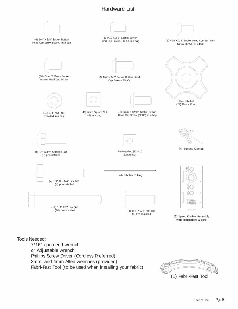
Pre-Installed (24) Plastic Knob
(8) 1/4 X 3/4" Carriage Bolt (8) pre-installed
(12) 1/4" Flat Washer(12) pre-installed
Pre-Installed (8) #10 Square Nut
(12) 1/4" X 2" Hex Bolt(10) pre-installed
(4) 1/4" X 1-1/4" Hex Bolt(4) pre-installed
(2) #10 X 1/4" X 1/2" Socket Head Shoulder Bolt (SHSB)
(2) pre-installed
Pre-Installed (8) 1/4" X 1" Socket Button Head Cap
Screw (SBHC)
Pre-Installed (8) 1/4" X 3/4" Socket Button Head Cap Screw
(SBHC)
(8) #10 X 3/8" Socket Head Counter Sink Screw (SHCS) in a bag
(16 #10 X 3/8" Socket Button Head Cap Screw (SBHC) in a bag(6) 1/4" X 3/8" Socket Button
Head Cap Screw (SBHC) in a bag
(8) 1/4" X 1/2" Socket Button Head Cap Screw (SBHC)
(10) 1/4" Nut Pre-Installed in a bag
(4) Fabrifast Tubing
(4) 1/4" X 3/4" Hex Bolt(4) Pre-Installed
(36) 6mm X 10mm Socket Button Head Cap Screw
(8) 6mm X 12mm Socket Button Head Cap Screw (SBHC) in a bag
(40) 6mm Square Nut(8) in a bag
(1) Speed Control Assembly with instructions & cord
(4) Bungee Clamps
Hardware List
Tools Needed: 7/�6” open end wrench or Adjustable wrench Phillips Screw Driver (Cordless Preferred) 3mm, and 4mm Allen wenches (provided) Fabri-Fast Tool (to be used when installing your fabric)
(�) Fabri-Fast Tool

Pg. 6 DID:07�006
Innovation and Evolution
Grace Quilting Systems have been developed over the past two decades with several original design innovations. Additionally, because of feedback from many of the thousands of quilters who have purchased and use our machine quilting systems, we have been able to make a frame that will truly enhance the entire process of machine quilting from
beginning to end.
WELCOME! As you begin assembly of your new Aluminum Frame home machine quilting system, keep in the mind the following:
�: The assembly process will be simple and step-by-step. 2: Read through each step completely before beginning that step. 3: Using the parts list as a reference, take the parts out of the box and make sure that you have them all. 4: Identify Hardware Packets: All hardware is separated by type and each packet is labeled for ease in identification. You will find packets located in a rectangular box.
Grace Quilting Frames and Hoops

Pg. 7DID:07�006
Step 1: Outer Leg Sub-AssemblyParts Needed: 4- Leg 4- Outer Leg Brace (Shorter)Tools Required: 4mm Allen Wrench (Provided)NOTE: It may be helpful to hold the square Nuts with a 7/�6” Open End Wrench while inserting them into the “T” slot in the legs.
1-1: The Outer Leg Braces are slightly shorter than the Middle Leg Braces. Separate the parts before assembly to minimize the possibility of using the wrong parts.
1-2: Insert the Square Nut (Pre-installed in the Leg Brace) into the “T” slot in the leg as shown in Fig. �-�.
1-3: Slide (2) Outer Leg Braces onto (2) Legs, as shown in Fig. �-2
1-4: Lay the Leg Assembly down as shown in Fig �-2 to simplify this step. Adjust the first installed Leg Brace using another leg brace to measure it’s location, as shown in Fig. �-3. Tighten the 6mm X �0mm SBHC screws in the Outer Leg Brace with a 4mm Allen Wrench to secure them into place.
NOTE: The first installed Leg Brace will later be used to support your Aluminum Frame’s shelf. If you would like the shelf to be higher, or lower than the suggested height be sure to make this adjustment now, since it may be difficult to make this change at a later time. Also, remember the height of the brace, and set the middle leg braces at the same height to ensure that the shelf sits level.
1-5: The bent ends of the top Outer Leg Brace need to be even with the top of the leg. This will put the bent-over flange on the Outer Leg Brace slightly higher than the top of the Leg.
1-6: Tighten the top Outer Leg Brace into it’s proper location using a 4mm Allen Wrench.
1-7: Repeat steps �-2 through �-6 to complete a total of two (2) Outer Leg Assemblies.
16"
Leg OutSd ASM
Fig. �-�
Fig. �-2
Fig. �-3
Leg
Outer LegBrace
�4"
Notice Flange Location

Pg. 8 DID:07�006
Leg OutSd ASM 2
Fig. 3-�
3-1: Attach a Frame End to each Outer Leg Sub-Assembly. Slide the 6mm Hex Nuts (Pre-installed in the Frame End) into the “T” Slot’s in the Legs, as shown in Fig. 3-�.
NOTE: Create a Left and a Right Outer Leg Assembly by attaching the frame ends as shown in Fig. 3-2, and Fig. 3-3.
3-2: Temporarily fasten the Frame Ends about �” down from the top of the leg, by tightening the pre-attached 6mm X �2mm SBHC screws with a 4mm Allen Wrench.
Step 3: Outer Leg AssemblyParts Needed: 2- Outer Leg Sub-Assembly �- Left Frame End �- Right Frame EndTools Required: 4mm Allen Wrench
Leg OutSd ASM 2
Fig. 3-2
Left
Leg OutSd ASM 2
Fig. 3-3Right
Frame End
Step 2: Frame End AssemblyParts Needed: �- Left Frame End �- Right Frame End 8- �2mm SHBC Screw 8- 6mm Square Nut
NOTE: To guarantee that you have a Left and Right Frame End, insert the screws through the side of each Frame End with the Logo’s painted on it.
2-1: Insert a �2mm SBHC Screw through each of the holes indicated in Fig. 2-� (on the Left, and Right Frame Ends). Partially thread a 6mm Nut onto the exposed end of each �2mm SBHC Screw (Thread the nut on until the screw barely shows on the outside of the nut, the nut shouldn’t easily fall off the screw, but will be very loose).
Left Frame EndRight Frame End
6mm square Nut
12mm SBHC Screw
Fig. 2-�
Pg. 9DID:07�006
A
DETAIL A SCALE 1 : 1.5
B
DETAIL B SCALE 1 : 1.5
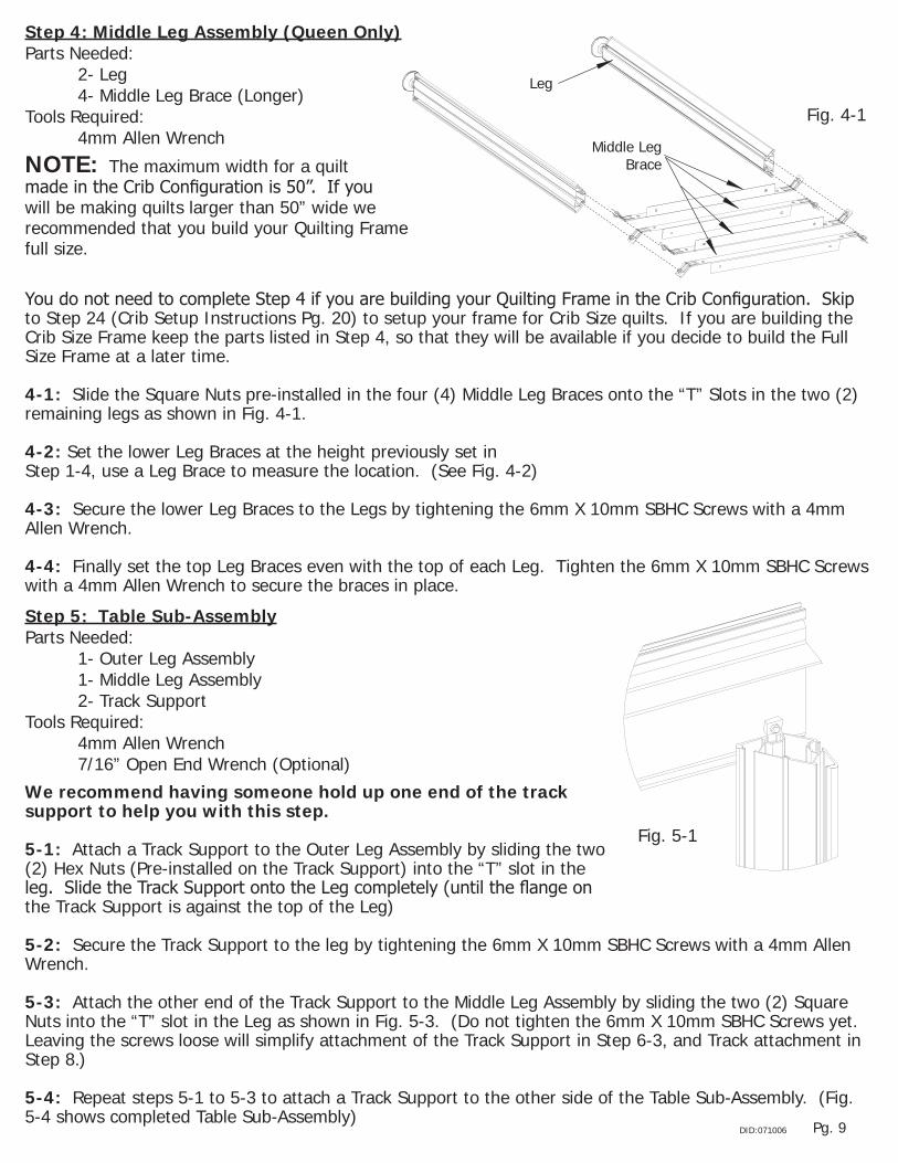
T Slot ASMStep 5: Table Sub-AssemblyParts Needed: �- Outer Leg Assembly �- Middle Leg Assembly 2- Track SupportTools Required: 4mm Allen Wrench 7/�6” Open End Wrench (Optional)
We recommend having someone hold up one end of the track support to help you with this step.
5-1: Attach a Track Support to the Outer Leg Assembly by sliding the two (2) Hex Nuts (Pre-installed on the Track Support) into the “T” slot in the leg. Slide the Track Support onto the Leg completely (until the flange on the Track Support is against the top of the Leg)
5-2: Secure the Track Support to the leg by tightening the 6mm X �0mm SBHC Screws with a 4mm Allen Wrench.
5-3: Attach the other end of the Track Support to the Middle Leg Assembly by sliding the two (2) Square Nuts into the “T” slot in the Leg as shown in Fig. 5-3. (Do not tighten the 6mm X �0mm SBHC Screws yet. Leaving the screws loose will simplify attachment of the Track Support in Step 6-3, and Track attachment in Step 8.)
5-4: Repeat steps 5-� to 5-3 to attach a Track Support to the other side of the Table Sub-Assembly. (Fig. 5-4 shows completed Table Sub-Assembly)
Fig. 5-�
16"
Leg InSd ASM
Fig. 4-�
Leg
Middle LegBraceNOTE: The maximum width for a quilt
made in the Crib Configuration is 50”. If you will be making quilts larger than 50” wide we recommended that you build your Quilting Frame full size.
Step 4: Middle Leg Assembly (Queen Only)Parts Needed: 2- Leg 4- Middle Leg Brace (Longer)Tools Required: 4mm Allen Wrench
You do not need to complete Step 4 if you are building your Quilting Frame in the Crib Configuration. Skip to Step 24 (Crib Setup Instructions Pg. 20) to setup your frame for Crib Size quilts. If you are building the Crib Size Frame keep the parts listed in Step 4, so that they will be available if you decide to build the Full Size Frame at a later time.
4-1: Slide the Square Nuts pre-installed in the four (4) Middle Leg Braces onto the “T” Slots in the two (2) remaining legs as shown in Fig. 4-�.
4-2: Set the lower Leg Braces at the height previously set in Step �-4, use a Leg Brace to measure the location. (See Fig. 4-2)
4-3: Secure the lower Leg Braces to the Legs by tightening the 6mm X �0mm SBHC Screws with a 4mm Allen Wrench.
4-4: Finally set the top Leg Braces even with the top of each Leg. Tighten the 6mm X �0mm SBHC Screws with a 4mm Allen Wrench to secure the braces in place.

Pg. �0 DID:07�006
Table ASM 1
A
DETAIL A SCALE 1 : 3
Fig. 5-2
Table ASM 1
A
DETAIL A SCALE 1 : 3
Fig. 5-3
TrackSupport
Table ASM 1
A
DETAIL A SCALE 1 : 3
Fig. 5-4
Step 6: Frame AssemblyParts Needed: �- Frame Sub-Assembly �- Outer Leg Assembly 2- Track Support
We recommend having someone hold up one end of the track support to help you with this step.
6-1: Attach a Track Support to the remaining Outer Leg Assembly by sliding two (2) of the Square Nuts (Pre-installed on the Track Support) into the “T” slot in the leg. Slide the Track Support onto the Leg completely (until the flange on the Track Support is against the top of the Leg).
6-2: Secure the Track Support to the leg by tightening the 6mm X �0mm SBHC Screws with a 4mm Allen Wrench.
6-3: Attach the other end of the Track Support to the Middle Leg, (part of the Table Sub-Assembly) by sliding the two (2) Square Nuts into the “T” slot in the Leg as done in Step 5-3, and as shown in Fig. 5-2. (Leave all four (4) of the 6mm X 10mm SBHC Screws in the Middle Leg loose. They will be tightened in Step 9-2)
6-4: Repeat steps 6-� to 6-3 to attach a Track Support to the other side of the Table Assembly.
Tools Required: 4mm Allen Wrench 7/�6” Open End Wrench (Optional)
Table ASM 2
Fig. 6-�

Pg. ��DID:07�006
Step 7: Shelf Brace AttachmentParts Needed: �- Table Assembly 4- Shelf Brace 6- �/4” X 3/8” SBHC Screw 6- �/4” NutTools Required: 4mm Allen Wrench 7/�6” Wrench
Fig. 7-�
�/4” Nut�/4” X 3/8” SBHC Screw
Outer Leg
Shelf Brace
Outer LegBraceNote: While attaching the Shelf Braces notice how the
brace is attached to the Frame. Fig. 7-�, and Fig 7-2 show proper Shelf Brace Attachment.
We Recommend that you have someone hold up the end of the shelf brace near the middle of the Frame while you attach the Shelf Braces to the outer leg Braces.
7-1: Attach a Shelf Brace to the lower Leg Brace on the Outer Leg Assembly with a �/4” X 3/8” SBHC Screw, and secure into place with a �/4” Nut, as shown in Fig. 7-�. 7-2: Attach another Shelf Brace to the lower Leg Brace on the Outer Leg Assembly, on the opposite end of the Frame as the one that you attached in step 6-�. Use the same procedure outlined in step 6-� to attach the Shelf Brace. See Fig. 7-2.
7-3: Attach the other end of the Shelf Braces to the lower Leg Brace on the Middle Leg Assembly by inserting a �/4” X 3/8” SBHC Screw through the hole in a Shelf Brace, and then through the hole in the Leg Brace. Finally insert the screw through the hole in the Shelf Brace that is on the other side of the Leg Brace. Secure the parts together with a �/4” Nut.
7-4: Repeat steps 7-� through 7-3, to attach Shelf Braces to the other end of the Leg Braces. See Fig. 7-3.
Fig. 7-2
�/4” Nut(Attach in Step 6-3) �/4” X 3/8”
SBHC Screw
MiddleLeg Brace
Shelf Brace
Middle Leg
Fig. 7-3
Shelf Brace 2
Step 8: Track AttachmentParts Needed: �- Table Assembly 2- �20” Plastic TrackTools Required: 4mm Allen Wrench8-1: Snap a �20” Plastic Track into the Track Supports on the Front, and also the Back of the Table Assembly as shown in Fig. 8-�. Start at one end of the track, and work your way down as the track snaps into place. (You may need to lightly tap the track to get it in place.) 8-2: After the Plastic Track is in place Tighten all of the screws holding the Track Supports to the Middle Legs with a 4mm Allen Wrench. (These screws were left loose in step 6-3.)
Track Install
Fig. 8-�
�20” Plastic Track
NOTE: To remove the track, start at one end, pry the track out with a small screw driver.

Pg. �2 DID:07�006
DETAIL A
Frame Side Adj
Fig. 8-2
DETAIL A
Frame Side Adj
Fig. 8-3
Step 9: Shelf AttachmentParts Needed: �- Table Assembly 2- Shelf Surface
9-1: Attach the plastic Shelf Surface, with it’s textured side UP to the Shelf Braces, and the lower Leg Braces with the Pre-Installed Double Sided Tape, as shown in Fig. 9-�. NOTE: To prevent the Shelf Surface from being attached out of square remove the backing from the tape, starting at one end of the Frame, and then only remove the Tape Backing in one (�) foot sections. Line up the Shelf Surface with the Shelf Braces, and press firmly in place before removing the next one (�) foot section of Tape Backing. Repeat this process until the entire Shelf Surface is attached.
9-2: Repeat Step 9-� so that both plastic Shelf Surfaces are attached to the Table Assembly.
#�0 X �/2" Counter sinkSocket Head Screw
Bottom Shelf
Shelf Attatchment
Shelf Surface
Fig. 9-�
8-3: Adjust the Frame Ends so that their top edges are even with the top edges of the Track supports, as shown in Fig. 8-2, and Fig. 8-3.
Step 10: Table Surface AttachmentParts Needed: �- Table Assembly 2- Table Surface 4- Table BraceTools Required: 3mm Allen Wrench
#�0 X �/2" Counter SinkSocket Head Screw
Table
Table Attatchment
Table Attatchment 01
Fig. �0-�
Table Surface
Table Brace
#�0 X 3/8” SHCS Screw
Front
Back
10-1: Attach all four (4) Table Braces to the Track Supports with the Pre-Installed #�0 screws. The Table Braces are attached to the bottom side of the Track Support Flange, with the Tape on the Table Brace facing up (Remove Pre-Installed #�0 screws from Table Braces before attaching them to the Track Supports).
10-2: Attach the Table Surface to the Frame using the same method used to attach the Shelf Surface in step 8, removing the Tape Backing in one (�) foot sections. Make sure that the Table surface is placed onto the Frame with it’s textured surface facing up. (Notice that the slots cut in the plastic Table Surface are closer to the back of the Table Assembly.) The Slots are in the table to attach the Pattern Perfect, and other optional accessories.
10-2: Repeat Step �0-� so that both plastic Table Surfaces are attached to the Table Assembly.

Pg. �3DID:07�006
�/4" X 3/4"Carriage Bolt
PME's 01
Step 11: Rail Bracket AttachmentParts Needed: �- Table Assembly 2- Fabric Layers Rail Bracket 2- Take-Up Rail Bracket11-1: Remove �/4” Carriage Bolts, and Plastic Knobs from the lower, slotted section of the Take-Up Rail Brackets, and Fabric Layers Rail Brackets.
11-2: Insert a �/4” X 3/4” Carriage Bolt through each of the two (2) square holes located at the front of each of the Frame Ends, as shown in Fig. ��-�, and Fig. ��-2. The Bolts are inserted from the inside of the Table assembly, facing out, this is shown more clearly in Fig. ��-2. 11-3: Now place a Fabric Layers Rail Bracket onto the 3/4” Carriage Bolts, inserted in step ��-2. The Carriage Bolts go through the large slot in the side of the Fabric Layers Rail Bracket.
11-4: Secure the Fabric Layers Rail Bracket to the Table assembly by threading a �/4” Plastic Knob onto each Carriage Bolt.
11-5: Repeat Steps ��-2 through ��-4 on the other end of the Table Assembly to attach the other Fabric Layers Rail Bracket.
11-6: Insert two (2) 1/4” X 3/4” Carriage Bolts through one of the five (5) available attachment positions indicated in Fig. ��-�. (The square holes are arranged in vertical pairs, which are provided to allow many different sizes of sewing machines to be used on the Quilting Frame. Try the middle position first, and adjust later if more, or less quilting area is desired.)
Fig. ��-�Left Frame End - Inside View
Fabric Layers Rail Bracket Attachment Location
Bolts pre-attached in Fabric Layers Rail Bracket
Take-Up Rail Bracket Attachment Locations
Table Details Omitted for clarity(This is the Frame End
shown by the word “Front” in Fig. 9-�)
(Pre-attached in Take-up Rail Bracket)
Take-Up PoleMount End
Quilt LayersPole Mount End
�/4" Plastic Knob
PME's Attatchment 02
Fabric Layers Rail Bracket (Fabric Layers Rail Brace)
�/4” Plastic Knob
Take-Up Rail Bracket (Take-Up Rail Brace)
Fig. ��-2
11-7: Now attach the Take-Up Rail Bracket to the Table Assembly by placing it onto the two (2) screws, just inserted into the table. The two (2) screws go through the large slot in the lower section of the Take-Up Rail Bracket. When you place the Take-Up Rail Bracket onto the Table Assembly be sure that the Bungee Arm near the top of the bracket is closer to the Fabric Layers Rail Bracket, as shown in Fig. ��-3.

Pg. �4 DID:07�006
Fig. ��-3
Step 12: Rail AssemblyParts Needed: 4- Ratchet 4- Rail End �6- #�0 X 3/8” SBHC Screw 4- Rail Coupler 4- Longer Rail 4- Shorter RailTools Required: 3mm Allen Wrench
Fig. �2-�
Rail Coupler3/8” SBHC Screw Rail
Crib Rail AssemblyParts Needed: 4- Ratchet 4- Rail End 8- #�0 X 3/8” SBHC Screw 4- Shorter RailTools Required: 3mm Allen Wrench
NOTE: If you are assembling your Quilting Frame in the Crib Configuration use the Crib Rail Assembly parts list. Also, if assembling the Crib Configuration, skip Step 12-1.
11-8: Secure the Take-Up Rail Bracket to the Table Assembly with two (2) �/4” Plastic Knobs.
11-9: Repeat Steps �0-6 through �0-8 to attach the remaining Take-Up Rail Bracket to the other end of the Table Assembly.
12-1: Attach two (2) Rails to each Rail Coupler using one #�0 X 3/8” SBHC Screw per Rail, as shown in Fig. �2-�. Tighten the #�0 Screws with a 3mm Allen Wrench (Be sure to use a short, and long rail for each rail assembly).
12-2: Attach a Ratchet to one of the ends of each of the rails with a #�0 X 3/8” SBHC Screw, as shown in Fig. �2-2 (Slide Rail into ratchet until you can see the entire hole in the nut).
12-2: Finally attach a Rail End to the open end of each of the rails with a #�0 X 3/8” SBHC Screw, as shown in Fig. �2-3 (Slide Rail into Rail End until you can see the entire hole in the nut).
Fig. �2-2
Ratchet
Fig. �2-3
Rail End

Pg. �5DID:07�006
Step 13: Rail Attachment to Table AssemblyParts Needed: 4- Rail Assembly 4- Table Assembly
Rail End Cap (Left End), orRatchetting Rail End Cap (Right End)
Rail Attatchment 01
Table, and Rail details omitted for clarity.
WARNING: Ratchet, or Rail End will become damaged if Rail is allowed to sag down while one end is attached to a Rail Bracket. We Recommend that you have someone hold up one end of the rail that you are working with to help you with this step.
13-1: Slide a Ratchet onto one of the wide slots in one of the Fabric Layers Rail Bracket’s on either end of the Table Assembly. Depress the Ratchet Mount Buttons while sliding the Ratchet into place. When the Ratchet is in place release the Ratchet Mount Buttons. The buttons should snap into the mounting holes in the Fabric Layers Rail Bracket.
13-2: Slide the Rail End, on the other end of the Rail into the same slot on the Fabric Layers Rail Bracket at the other end of the Table Assembly. Again, depress the Ratchet Mount Buttons while sliding the Rail End into place. Once the Rail is in place the Ratchet Mount Buttons should snap into the mounting holes in the Fabric Layers Rail Bracket.
13-3: Repeat Steps �3-�, and �3-2 to attach the remaining two (2) rails to the Fabric Layers Rail Bracket’s at each end of the Table Assembly. Make sure that all of the Ratchets are mounted on the same end of the Table Assembly.
13-4: Attach the final Rail assembly to the Take-Up Rail Bracket exactly the same way as you attached all of the other rails to the Fabric Layers Rail Bracket. Again, remember to attach the Ratchet to the same end of the Table Assembly as all of the other Ratchets.
Fig. �3-�
Fig. �3-2
Step 14: Top Plate SidesParts Required: 4- �/4” X 3/4” HEX Bolt 4- �/4” Nut �- Lower Left Carriage Side �- Lower Right Carriage Side �- Right Upper Carriage Side �- Left Upper Carriage Side �- Top PlateTools Required: 7/�6” Wrench
Attach the Carriage Sides to the Top Plate.
14-1: Next insert a �/4” X 3/4” HEX Bolt through each of the holes in the Lower Left Carriage Side, and then throught the holes in the top plate.
14-2: Secure the Lower Left Carriage Side to the Top Plate by applying nuts to the exposed end of the HEX Bolts. Tighten the nuts securely with a 7/�6” wrench. Fig �4-�.
14-3: Repeat Steps �4-� through �4-3, this time using the Lower Right Carriage Side to attach the Right Carriage Side to the Top Plate.

Pg. �6 DID:07�006
�/4" Nut
3/4" HEX Bolt
Top Carriage ASM 1
�/4" Nut
3/4" HEX Bolt
Top Carriage ASM 1
Fig. �4-�
Step 15: Top Plate - Final AssemblyParts Required: 2- Handle Brace Assembly �- Top Plate Assembly
15-1: Remove the pre-installed 2” Hex Bolts, and �/4” Plastic Knobs from the ends of each Handle Brace Assembly.
15-2: Pull the Carriage Sides apart slightly, to allow the Handle Brace Assembly to be inserted between them. The round stems on each end of the Handle Braces Fit into the round holes in the Plastic End Caps. Insert a Handle Brace Assembly into the front as well as the back of the Top Plate Assembly.
15-3: After the Handle Brace Assemblies are in place, insert a 2” Hex Bolt through the Handle brace, push it all the way through the Plastic End Cap.
15-4: Secure the Handle Brace Assemblies into place by fastening a �/4” Plastic Knob onto each 2” Hex Bolt.
2" Hex Bolt�/4" Plastic Knob
Top Carriage ASM 2
Front
Back
�/4” Plastic Knob2” Hex Bolt
Fig. �5-�
Lower Right Carriage Side
Lower Left Carriage Side
Angled Side Facing Back Adjusting Lever
(Not Visible)
Adjusting Lever
Upper Right Carriage Side Upper Left
Carriage Side
Fig. �4-2
NOTE: The Plastic Caps on the ends of the upper aluminum parts have teeth on one side, and are smooth on the other side. Make sure that when the Upper Carriage sides are installed that the teeth face towards the inside of the carriage.
14-5: Release the Adjusting Levers on each of the Lower Carriage Sides. Now Insert the Upper Carriage Sides into the Lower Carriage Sides, and lock them into place with the Adjusting Levers.

Pg. �7DID:07�006
Step 16: Bottom Plate AssemblyParts Required: 2- Bottom Plate Side 2- Bottom Plate EndTools Required: 4mm Allen Wrench
Bottom Plate Side
Bottom Plate End
�/2” Screw
16-1: Remove the Pre-Installed �/2” Screws from all of the Bottom Plate Sides.
16-2: Attach the Bottom Plate Ends to the Bottom Plate Sides using the �/2” screws that you removed in step �6-�. Make sure that the Bottom Plate Ends are attached with their wheels facing in, as shown in Fig. �6-�.
Step 17: Bottom Plate PlacementParts Required: �- Bottom Plate Assembly �- Table Assembly - Complete
Fig. �7-�
Place Bottom Plate onto the Table Assembly.
17-1: First, remove the Take-Up Rail from the Table Assembly. This is the Rail located right over the middle of the Table, as shown in Fig. �6-�.
17-2: Make sure that all four (4) wheels on your Bottom Plate are on the Plastic Track. The Bottom Plate should roll smoothly on the Track.
Fig. �6-�
Step 18: Top Plate PlacementParts Required: �- Top Plate - Final Assembly �- Table Assembly - Complete w/Bottom Plate
Fig. �8-�
Place the Top Plate Assembly onto the Bottom Plate, as shown in Fig. �8-�.
18-1: Make sure that all four (4) wheels are on the track, located on the top side of the Bottom Plate, and that the Top Plate rolls smoothly.
NOTE: The completely assembled Top Plate, with Bottom plate is called the Carriage, and will be referred to as the carriage throughout the remaining text, except for when instructions refer to features only on one item or the other.

Pg. �8 DID:07�006
Adjusting Lever Fig. �9-�
Loosen Knobs
Fig. �9-2
Fig. �9-3
19-4: Roll the Carriage all the way to one end of the Table.
19-5: Now, put the Take-Up Rail through the open area above the throat of your Sewing Machine.
19-6: Attach the Take-Up Rail to the Take-Up Rail Brackets as previously done, in Step �3-4.
Step 20: Leveling the TableNow that you have completed the assembly of your Aluminum Frame Quilting Machine, adjust the table so that it is level.
20-1: There are Leveling Feet at the bottom of each of the Table Legs. Adjust the Leveling feet so that the Carriage will not roll from side to side, or from front to back when it is left at any point at the table.
Step 21: Handle Adjustment
Adjust the handles for optimal performance, and quilting comfort.
21-1: The Following handle adjustments are possible.Raise the height of the Handles (Fig. �9-�) Rotate the Handles, front to back (Fig. �9-2)Rotate the handles side to side (Fig. 2�-2)The handles can be adjusted wide or narrow (Fig. 2�-�)And finally the Handles can be adjusted forward and back (Fig. 21-3)
Fig. �9-4
Step 19: Sewing Machine PlacementParts Required: �- Sewing Machine (Your Sewing Machine) �- Table Assembly - Complete w/Carriage
Place your Sewing Machine onto the Carriage, as shown in Fig. �9-3.
19-1: Raise the upper portion of the Carriage Sides high enough to allow your sewing machine to slide onto the Top Plate. Now, lock the Handles into place in the higher position with the Adjusting Lever.
NOTE: You can also gain some clearance for your sewing machine by rotating the Back Handle Brace Assembly up, out of the way. (Fig. �9-2)
19-2: Place your Sewing Machine onto the Top Plate, and center it, both from side to side, as well as from front to back.

Pg. �9DID:07�006
Fig. 2�-�Fig. 2�-2
Loosen Knobs
Fig. 2�-3
Release Adjustment Lever
Step 22: Upper Laser Pointer AttachmentParts Required: �- Laser Pointer �- Top Plate Assembly
Possible mounting locations
Fig. 22-�
Attach Laser to Carriage Assembly
NOTE: The Laser will be more useful in different locations, depending on the application. Determine the best location for the Laser before mounting it. Fig. 22-1 shows the available Laser Pointer mounting locations on the upper handles (Mount Laser Here if you want to trace patterns printed, or placed on the quilt, it is also useful to trace previously sewn patterns, to improve repeated pattern accuracy. Fig. 23-1 shows the lower mounting locations. (Mount Laser here if you would like to trace patterns printed on paper.)
22-1: Remove one of the Plastic Knobs from one of the bolts that hold the Handle Brace to the Carriage Sides.
22-2: Slide the Laser Pointer onto the exposed end of the bolt.
22-3: Secure the Laser Assembly to the carriage with the knob that you just removed.Step 23: Lower Laser Pointer AttachmentParts Required: �- Laser Pointer �- Laser Pointer Lower �- Top Plate Assembly
Fig. 23-�
Mount the Laser Pointer to one of the lower mounting locations.
23-1: Disassemble the Laser Pointer Assembly. (It is shipped ready to attach to the upper handles.)
23-2: Insert the 2” Hex Bolt through the Laser Pointer Ball Swivel.
23-3: Next insert the Hex Bolt, and Ball Swivel into the Laser Mount, in the Lower Carriage Side. The Hex Bolt goes through the slot in the front of the Laser Mount.
23-4: While holding the Hex Bolt into the Laser Mount, put the Laser Pointer Ball Swivel Clamp onto the exposed end of the Hex Bolt.
23-5: Next, slide the Laser Pointer onto the Bolt. The Laser Pointer should sit into the saddle on the end of the Laser Pointer Ball Swivel Clamp.
23-6: Secure the Laser Pointer Assembly to the Carriage Assembly by tightening a �/4” Plastic knob onto the exposed end of the Hex Bolt.

Pg. 20 DID:07�006
Congratulations This completes your Quilting Frame setup.Please make sure that all screws are completely tightened before continuing. Now you need to apply your quilt fabric to the Quilting Frame. Detailed instructions explaining how to put your fabric onto the frame are located on Pg. 23
A
DETAIL A SCALE 1 : 1.5
B
DETAIL B SCALE 1 : 1.5
T Slot ASMStep 24: Crib Table AssemblyParts Needed: 2- Outer Leg Assembly 2- Track SupportTools Required: 4mm Allen Wrench 7/�6” Open End Wrench (Optional)
NOTE: The maximum width for a quilt made in the Crib Configuration is 50”. If you will be making quilts larger than 50” wide we recommended that you build your Quilting Frame full size.
24-1: Attach a Track Support to the Outer Leg Assembly by sliding the two (2) Hex Nuts (Pre-installed on the Track Support) into the “T” slot in the leg. Slide the Track Support onto the Leg completely (until the flange on the Track Support is against the top of the Leg).
24-2: Secure the Track Support to the leg by tightening the �/4” X 3/8” SBHC Screws with a 4mm Allen Wrench.
24-3: Attach the other end of the Track Support to the other Outer Leg Assembly by sliding the two (2) Hex Nuts into the “T” slot in the Leg as shown in Fig. 24-2. Tighten the3/8” SBHC screws with a 4mm Allen Wrench, as done in step 24-2.
NOTE: It may be helpful to hold the Hex Nuts (to keep them aligned with the “T” slot) with a 7/�6” Open End Wrench while inserting them into the “T” slot in the legs, since there is limited clearance, especially on the Hex Nuts closest to the flange.
24-4: Repeat steps 24-� through 23-3 to attach the other Track Support to the Outer Legs.
Fig. 24-�
Fig. 24-2
Track Support

Pg. 2�DID:07�006
Step 25: Crib Shelf Brace AttachmentParts Needed: �- Crib Table Assembly 2- Shelf Brace 4- 3/8” SBHC Screw 4- �/4” NutTools Required: 4mm Allen Wrench 7/�6” Open End Wrench
Note: While attaching the Shelf Braces notice that there are four (4) threaded holes on one of the sides of the brace. Make sure that these holes face up. Also, make sure that the side of the brace without holes in it faces out.
25-1: Attach a Shelf Brace to the lower Leg Brace on one of the Outer Leg Assemblies with a �/4” X 3/8” SBHC Screw, and secure into place with a �/4” Nut, as shown in Fig. 24-�. 25-2: Attach the other end of the Shelf Brace to the lower Leg Brace on the other Outer Leg Assembly by inserting a �/4” X 3/8” SBHC Screw through the hole in the Shelf Brace, and then through the hole in the Leg Brace. Secure the brace into place with a �/4” Nut.
25-3: Attach the remaining Shelf Brace as previously done in steps 24-�, and 24-2.
�/4” Nut
Shelf Brace
3/8” SBHC Screw
Fig. 25-�
Fig. 25-2Step 26: Crib Track AttachmentParts Needed: �- Crib Table Assembly 2- Crib Track (60”)Tools Required: 4mm Allen Wrench 7/�6” Open End Wrench
Fig. 26-�
26-1: Snap a 60” Plastic Track into the Track Supports on the Front, and also the Back of the Crib Table Assembly as shown in Fig. 26-�. Start at one end of the track, and work your way down as the track snaps into place. (You may need to lightly tap the track to get it in place.) 26-2: Adjust the Frame Ends so that their top edges are even with the top edges of the Track supports, as shown in Fig. 8-2, and Fig. 8-3 (Pg. �2).
NOTE: To remove the track use a small Screwdriver to pry up one end first.

Pg. 22 DID:07�006
Step 27: Crib Shelf AttachmentParts Needed: �- Crib Table Assembly �- Shelf Surface
Shelf Surface
Fig. 25-�
Step 28: Crib Table Surface AttachmentParts Needed: �- Crib Table Assembly �- Table Surface 4 - #�0 X 3/8” SHCS Screw 2- Table BraceTools Required: 3mm Allen Wrench
This concludes the part of the Crib Configuration setup that is different from Full Frame setup. At this point go back to Step ��, (on Pg. �3), and follow the remaining steps to complete the setup of your Quilting Frame. Any Crib Configuration steps that vary from Full Frame setup will be indicated in the instruction text throughout the remainder of the assembly process.
27-1: Attach the plastic Shelf Surface, with it’s textured side UP to the Shelf Braces, and the lower Leg Braces with the Pre-Installed Double Sided Tape, as shown in Fig. 27-�. NOTE: To prevent the Shelf Surface from being attached out of square remove the backing from the tape, starting at one end of the Frame, and then only remove the Tape Backing in one (�) foot sections. Line up the Shelf Surface with the Shelf Braces, and press firmly in place before removing the next one (1) foot section of Tape Backing. Repeat this process until the entire Shelf Surface is attached.
28-1: Attach both Table Braces to the Track Supports with the Pre-Installed #�0 screws. The Table Braces are attached to the bottom side of the Track Support Flange, with the Tape on the Table Brace facing up.
28-2: Attach the Table Surface to the Frame using the same method used to attach the Shelf Surface in step 27, removing the Tape Backing in one (�) foot sections. Make sure that the Table surface is placed onto the Frame with it’s textured surface facing up. (Notice that the slots cut in the plastic Table Surface are closer to the back of the Table Assembly.) The Slots are in the table to attach the Pattern Perfect, and other optional accessories.
Table Brace
Table Surface
#�0 X 3/8” SHCS Screw
Fig. 27-�

Pg. 23DID:07�006
Congratulations! You have completed the assembly of your Aluminum Frame Quilting Frame.
All that remains is to install your fabric and begin quilting! (You’ll notice you still have Bungee Clamps leftover. These will be assembled in conjunction with your fabric installation).
With the Grace, specially designed Fabri-Fast rails, installing your fabric is easier on the Aluminum Frame than on any other frame. Each rail has a Fabri-Fast slot and accompanying tubing. These work together to make your fabric installation much easier and faster than using tape, tacks or Velcro®.
Before you begin, please locate the plastic Fabri-Fast tool included in your shipment.
We recommend you begin with practice material allowing you to experiment with machine settings and stroke techniques.
NOTE: As you cut your fabric layers, we recommend making the quilt backing about 6-8” longer and 2-4” wider than your top. This will allow for a little give in the backing, especially if using thicker batting.
Aluminum Frame Fabric Installation
Rail Rotation: It is important that each rail rotates the correct direction to apply tension to your quilt layers correctly. Light tension is applied to your quilt fabric to remove wrinkles, and to allow the fabric to be sewn together consistently throughout the entire quilt. The Ratchet Rail ends allow you to limit the direction that each rail rotates. The Ratchets are universal, in that the direction of rotation can be changed by simply sliding the direction lever from one side to the other. The ratchet can also be set to a neutral position by sliding the direction lever to the center position. Each rail will always rotate in the direction toward which its lever is slid. When switching the ratchet’s direction of rotation, or when switching the ratchet into the neutral position you need to rotate the rail in it’s previous direction of rotation slightly, to allow the ratchet to release, before the ratchet will be in the neutral position, or be able to rotate in the opposite direction.
Installing Fabric Layers onto the Rails (Preview): Center your cloth lengthwise along the rail. Using Grace’s Fabri-FastTM System, take a piece of plastic tubing (cut to the appropriate length), and, holding your fabric to the slot (lining up the edge), press the tubing over the fabric and into the slot. Use the Fabri-Fast tool to press the rest of the tube and fabric in quickly and easily. (Detailed instructions begin on page 24.)
Methods of Installation: 1: The recommended method for installing fabric onto the rails is to apply your fabric layers directly to the rails. 2: You may also make and use Cloth Leaders (instructions on Pg. 27).
OVERVIEW: This is an outline to show which fabric layer goes onto each rail, and the direction that each rail should rotate.
Step 1: Install Batting to Batting rail and roll up.Step 2: Install Quilt Top to the Quilt Top rail and roll up.Step 3: Install Backing to Backing rail and roll up.Step 4: Attach Quilt Layers to Take-Up rail.

Pg. 24 DID:07�006
Step 1: Batting
NOTE: A light, bonded batting is recommended.
1-1: Center the batting on the batting rail and attach one end of the batting using the fabri-fast tubing. (NOTE: Fabri-Fast tubing will work with most batting, however, if the batting is too thick to squeeze into the slot, you may tape the batting to the rail to keep it in place).
1-2: Roll the batting onto rail. The direction that you roll the batting onto the rail doesn’t matter. The important thing to watch when rolling batting onto the rail is that the batting isn’t stretched. Always keep the ratchet on the batting rail in the Neutral Position to prevent any tension from being applied to the batting (See Fig. FI�-�).
Step 2: Quilt Top to Quilt Top Rail
2-1: Determine which end of your quilt will be the front.
2-2: Place the quilt top onto the table surface with its finished side facing up. Line up the center of your fabric layer with the center of the quilt top Rail. Attach the back edge of your quilt top to the quilt top rail. This is to be done with the finished side of the fabric facing up. Do not stretch or pull the fabric during this process. Let it lay as naturally as possible.
2-3: Make sure that the Qult Top’s Rail’s Ratchet is in the Locked-Clockwise Position (See Fig FI�-�). Roll your quilt top onto the Quilt Top Rail completely. Again, be sure the fabric stays lined up. Smooth out any wrinkles as you roll by brushing the fabric from the center out, being very careful not to stretch or pull the fabric excessively.
Step 3: Quilt backing to Backing rail
3-1: To begin, determine which will be the front and back edges of your quilt backing. (Your quilt can’t exceed (��0” wide) the maximum quilt width of your Aluminum Quilting Machine. Your quilt’s length is not limited)
Take-Up Rail
Backing Rail
Quilt Top Rail
Fig. FI�-�
Take-Up Rail
Quilt Backing
Backing Rail
Quilt TopQuilt Top Rail
Batting
Batting Rail
Fig. FI�-2
Batting Rail

Pg. 25DID:07�006
NOTE: If your backing is made up of more than one piece of fabric, cut your selvedges off and flatten out the seams with an iron to allow the backing the proper give it needs.
3-2: Place your quilt backing onto the table surface good side down. Line up the center of your fabric layer with the center of the Backing Rail. Attach the backing with its finished side of the fabric facing the rail. Do not stretch or pull the fabric during this process. Let it lie as naturally as possible.
3-3: Make sure that the Backing Rail’s Ratchet is in the Locked Counter-Clockwise Position (See Fig FI�-�). Roll your backing onto the backing rail completely. Watch to make sure the fabric stays lined up. Smooth out any wrinkles as you roll by brushing the fabric from the center out. However, be very careful not to stretch or pull the fabric excessively.
NOTE: It is important that you roll the rail the proper direction so the fabric rolls onto the quilt top rail the right way (If the rail always rotates the correct direction, as indicated in Fig. FI�-� you will avoid potential problems with the quilt fabric).
Step 4: Attaching Quilt Layers to the Take-Up Rail (See Fig. FI4-4).
4-1: Put the Take-Up Rails Ratchet into the Counter-Clockwise position, to ensure that it always rotates the correct direction.
4-2: Put the Backing Rail’s Ratchet into the Neutral position. Now take the end of the quilt backing and attach it to the take-up rail with the fabri-fast tubing, be careful to not stretch your fabric. Put the Ratchet back into the Locked Counter-Clockwise Position, and roll the Backing Rail to apply just enough tension to the Backing fabric. The fabric should be loose, but not sagging (See Fig. FI4-�).
4-3: Next, bring your Batting up in between the Quilt Top Rail and Backing Rail and drape over the Backing. Lay it along the edge of the Take-Up Rail (See Fig. FI4-2).
4-4: Put the Quilt Top’s ratchet into the Neutral Position. Now, bring the edge of the Quilt Top up over the Backing and Batting and lay it over the batting along the Take-Up Rail. Pin your Top and Batting to the Backing, in a straight line along the edge of the Take-up Rail. You may also baste the edge with your sewing machine (See Fig. FI4-3). Put the Quilt Top’s ratchet back into the Locked Clockwise Position.
You are now ready to sew your desired patterns onto your quilt.
Quilt Backing
Take-Up Rail
Backing Rail
Quilt Top Rail
Batting Rail
Fig. FI4-�
Fig. FI4-2
Batting Rail
Quilt Top Rail
Backing RailTake-Up Rail
Batting
Backing RailQuilt Top Rail
Batting Rail
Take-Up Rail
Batting
Quilt Top
Fig. FI4-3

Pg. 26 DID:07�006
Rolling your fabric
When you have completed your work area and are ready to roll to the next, simply switch the Quilt Top, and Backing Ratchets into the neutral position, allowing them to roll freely. The Batting Ratchet should already be in the Neutral position. Roll the Take-Up Rail forward, rolling the sewn quilt area onto that rail. After you have advanced your quilt to the next location, switch each Rail’s Ratchet lever to it’s pre-determined position, and re-apply just enough tension to hold the fabric up without sagging, and without stretching the fabric.
TIP! As you roll the quilt forward, the quilt will accumulate on the Take-Up Rail. Raise the Take-Up Rail Bracket as needed, so that the bottom of the rolled up fabric stays about �/�6” above the sewing machine base. Failing to do so will cause your Carriage Assembly to roll less smoothly.
Turning Quilt Around (This will enable you to quilt the entire quilt surface.)
Step �: Begin pin basting your quilt when the quilt rolled up onto the Take-Up Rail is larger than desired. Pin baste all of the remaining un-quilted material.
Step 2: Detach the individual layers of fabric from their rails (Backing, Top, and Batting) and roll them up onto the Take-Up Rail. (Keep The quilt attached to the Take-Up Rail.)
Step 3: Remove the Backing Rail. Remember to support the rail to prevent the Rail Ends from being broken. Temporarily place the rail on the floor in front of your quilting frame. (We recommend having someone help you with this step and also with step 4.)
Step 4: Remove the Take-Up Rail (with quilt rolled onto it) and put it into the highest notch in the Fabric
Fig. FI4-4
Quilt Top
Backing
Batting
Fig. RF�-�

Pg. 27DID:07�006
Layers Rail Brackets (the Backing Rail Location), making it the New Backing Rail. Now put the other rail in the Take-Up Rail location, making it the New Take-Up Rail. Step 5: Attach the (quilt) two layers of fabric, and the batting to the New Take-Up Rail, using the Fabri-Fast Tubing. Step 6: Roll the quilt off of the New Backing Rail, onto the New Take-Up Rail. Place the New Take-Up Rail’s ratchet into the counter-clockwise position.
Step 7: Place the ratchet in neutral and roll the quilt back onto the other rail with its ratchet locked in the counter-clockwise position until you can see the area where you left off quilting. Step 8: Place the ratchet on the New Take-Up Rail in the counter-clockwise ratcheting position, add a little tension to your fabric and you are ready to begin quilting again.
NOTE: As you advance to the next area roll the fabric off of the Take-Up Rail and out of the throat of the sewing machine and your finished quilt will now be rolled up onto the Backing Rail at the front of the frame rather than onto the Take-Up Rail. Making Cloth Leaders
�: First, select your cloth leader material. We recommend using a good quality muslin or similar fabric that has a good thread count. Be aware, however, that if the fabric is too thick, it may prove more difficult getting it installed into the rail slot.
2: Surge or hem your cloth leaders on all sides.
3: Make cloth leaders in the following widths. (The recommended length is �05”, this length will accommodate any width of quilt that can be made on your Aluminum Frame Quilting Machine.)
4: Make a dashed line along the length of your leader about ½” in from the edge with a pen or marker. You will use this as a guide to help you insert your leader into the slot in straight line. (OPTIONAL: For a straighter cloth leader installation, some may consider it easier to make a hem and then push the tubing into the hem before installing it into the slot. If you wish to do this, create a hem on one end of each leader by folding over the fabric one inch (�”), and, using your foot pedal as a guide, stitching the fabric together 3/4” from the fold. This will leave about ¼” of fabric beyond the stitching. Leave the edges open on both ends. You may then slide your tubing into the hem, Fig. CL�-�).
5: Mark each cloth leader at the center (length-wise).
6: Mark (or baste) a straight line about ½” in from the opposite (non-hemed, or non-dashed) end of the leader. This will be the line to which you attach your fabric layer.
7: Center your cloth leader lengthwise along the rail. Using Grace’s Fabri-FastTM System, take a piece of
plastic tubing (cut to the appropriate length), and, holding your cloth leader to the slot (lining up the dashed line), press the tubing over the leader and into the slot. Use the Fabri-Fast tool to press the rest of the tube and fabric in quickly and easily. (If you have made a hem, line up this hem w/ tubing over the slot and press it into the slot using the Fabri-Fast tool.
5"13
"20
1/2
"
Take Up Leader
Backing Leader
Top Fabric Leader
3/4" Casing
3/4" Casing
3/4" Casing

Pg. 28 DID:07�006
Fabri-Fast Tubing
Cloth Leader
Fig. CL�-�
Bungee Clamp InstallationThere are 4 Bungee Clamps provided with your Aluminum Frame Quilting Frame. The Bungee Clamps allow you to easily add side tension to your quilt fabric. Clip your Bungee Clamps to the quilt fabric, then insert the loose Bungee end through the Bungee Holder as shown in Fig. BC�-�, looping it back into the Bungee Holder. Apply some tension to the Bungee then slide the bungee that is in the crescent moon side of the bungee holder toward either tapered side to grip the bungee in place. Fig. BC�-�
There are many optional accessories available for your Aluminum Frame Quilting frame.
Lamp Holder Accessory: Your Quilting Frame was shipped with Lamp Brackets, as well as the hardware required to attach the brackets. The Lamp Brackets are easily attached to the Handle Braces as Shown Fig. LH�-�. Lamps, and other accessories can be attached to the Lamp Brackets. You can purchase a Lamp from the Grace Company web site, www.graceframe.com, or by calling Your Grace Company Distributor.
Optional Accessories
8: With Cloth Leaders in place, pin your Quilt Fabric to the Leaders, rather than attaching it directly to the Rails.
Sewing Tips• Be careful not to sew too close to the edge, to prevent hitting your Bungee Clamps, or running off the edge of the quilt. Also, if you are using side leaders, avoid accidently stitching the leaders to your quilt.
• If your quilt will fit onto your frame Length-wise attach your quilt’s fabric to the rails along it’s length. You will have to roll the quilt less often, since your work surface will be as large as possible. Also, the quilt will not be as fat under the arm of the machine when you get to the end.
• You will need 4-5 bobbins to quilt a small sized quilt (less than a queen).
• Make sure to turn off your sewing machine any time you leave your quilting room, especially if you are using the peddle pushing mechanism. If the mechanism pushes the pedal at all it may cause your sewing machine and peddle to get very hot.
• Keeping the fabric on the Take-Up Rail touching the bed of the sewing machine, instead of above the bed yields better results. If the fabric is too high off the bed, bouncing will occur.
• When rolling the quilt, pull the batting a little to each side to make sure that it is not bunching. After rolling and tightening all the rollers, check under the quilt to see that the back is smooth.