MultiControl V2.3 en - Interroll Group | Diagnostic informationError information..... 5051 Network...
64
INSPIRED BY EFFICIENCY MultiControl for RollerDrive Sensor 1 I/0 1 RD 1 Link A RD 2 Sensor 2 I/0 2 Sensor 1 ® I/0 1 RD 1 Link A RD 2 Sensor 2 I/0 2 Power Ready Com Fault Sensor 1 I/0 3 RD 3 Link B RD 4 Sensor 4 I/0 4 Sensor 1 I/0 3 RD 3 Link B Sensor 4 RD 4 I/0 4 4 3 1 2 User Manual Interroll MultiControl Version 2.3 (01/2017) en-US Translation of original instruction manual
Transcript of MultiControl V2.3 en - Interroll Group | Diagnostic informationError information..... 5051 Network...

INSPIRED BY EFFICIENCY
MultiControl
for RollerDrive
Sensor 1
I/0 1
RD 1
Link A
RD 2
Sensor 2
I/0 2Sensor 1
®
I/0 1RD 1Link A
RD 2Sensor 2I/0 2
PowerReadyCom
Fault
Sensor 1I/0 3RD 3
Link BRD 4Sensor 4I/0 4
Sensor 1I/0 3
RD 3
Link B
Sensor 4
RD 4
I/0 4
43
1
2
User Manual
Interroll MultiControl
Version 2.3 (01/2017) en-USTranslation of original instruction manual

Manufacturer's address
Interroll Engineering GmbH Hoeferhof 16D-42929 Wermelskirchen Ph. +49 2193 23 0 Fax +49 2190 2022 www.interroll.com
Contents
We strive for the information presented to be correct, up to date and complete. We havecarefully worked out the contents of this document. However, we assume no liability forthe information. We expressly deny any liability for damages or consequential damagesthat are connected in any form with the use of this document. We reserve the right tochange the documented products and product information at any time.
Copyright / intellectual property right
Texts, images, graphics and the like as well as their arrangement are protected bycopyright and other protection laws. Reproduction, modification, transfer or publicationof any part or the entire content of this document in any form is prohibited. Thisdocument is intended exclusively for information purposes and for the intended use anddoes not authorize the reproduction of the respective products. All signs contained in thisdocument (registered trademarks, such as logos and business designations) are theproperty of Interroll Engineering GmbH or third parties and may not be used, copied ordistributed without prior written consent.
1108094 Version 2.3 (01/2017) en-USTranslation of original instruction manual
Interroll MultiControl
Version 2.3 (01/2017) en-USTranslation of original instruction manual
3
Table of ContentsIntroduction................................................................................................................................ 6
Information about the manual .................................................................................................................... 6Contents ...................................................................................................................................................... 6The manual is part of the product ....................................................................................................... 6
Warning notices in this manual .................................................................................................................. 6Symbols............................................................................................................................................................. 6
Safety ......................................................................................................................................... 7State of the art................................................................................................................................................ 7Intended use .................................................................................................................................................... 7Personnel qualification .................................................................................................................................. 7
Operators ................................................................................................................................................... 7Qualified person ....................................................................................................................................... 7Electricians .................................................................................................................................................. 7
Dangers............................................................................................................................................................. 8Bodily injury................................................................................................................................................ 8Electricity ..................................................................................................................................................... 8Working environment .............................................................................................................................. 8Faults during operation........................................................................................................................... 8Maintenance .............................................................................................................................................. 8Accidental motor start ............................................................................................................................. 8
Interfaces to other devices........................................................................................................................... 9Operating modes ........................................................................................................................................... 9
Normal mode............................................................................................................................................. 9Special mode ............................................................................................................................................. 9
Product information................................................................................................................ 10Product description ..................................................................................................................................... 10
Teach-In procedure ............................................................................................................................... 10Energy recovery / Overvoltage protection ................................................................................... 10Overload protection device ............................................................................................................... 10
Structure ........................................................................................................................................................ 11Scope of supply ........................................................................................................................................... 12Nameplate .................................................................................................................................................... 12Technical data .............................................................................................................................................. 13Dimensions..................................................................................................................................................... 13
Transport and storage ............................................................................................................ 15Ambient conditions for transport and storage.................................................................................... 15Transport........................................................................................................................................................ 15Storage .......................................................................................................................................................... 15
Assembly and installation ..................................................................................................... 16Warning information for assembly......................................................................................................... 16Assembly of MultiControl.......................................................................................................................... 16
Initial assembly........................................................................................................................................ 16Repeated assembly ............................................................................................................................... 17
Warning notices concerning the electrical installation ...................................................................... 18

Interroll MultiControl
Table of Contents
4 Version 2.3 (01/2017) en-USTranslation of original instruction manual
Electrical installation ................................................................................................................................... 19Connect the power supply .................................................................................................................. 19Connecting the RollerDrive ................................................................................................................. 20Connecting the bus................................................................................................................................ 21Connecting the sensors ........................................................................................................................ 22
Initial startup and operation.................................................................................................. 23Checks before initial startup..................................................................................................................... 23Configuration options ................................................................................................................................ 23
User interface.......................................................................................................................................... 24Service Data Objects (SDO)............................................................................................................... 25Magnetic sensor ..................................................................................................................................... 25
Configuring MultiControl .......................................................................................................................... 28Setting bus parameters ........................................................................................................................ 28Selecting the application module ...................................................................................................... 29Configuring inputs and outputs.......................................................................................................... 29Defining the motor type....................................................................................................................... 29Switching off the LED indicators ........................................................................................................ 29Defining the error behavior ................................................................................................................ 29Resetting to factory settings................................................................................................................ 30Reading out version information ....................................................................................................... 30
Operation...................................................................................................................................................... 31Pre-startup checks.................................................................................................................................. 31Start........................................................................................................................................................... 31Stop ........................................................................................................................................................... 31
Process data ................................................................................................................................................. 32Process image of the inputs ................................................................................................................ 32Process image of the outputs.............................................................................................................. 34
Maintenance and cleaning.................................................................................................... 37Warning notices concerning maintenance and cleaning.................................................................. 37Maintenance................................................................................................................................................. 37
Checking MultiControl.......................................................................................................................... 37Replacing MultiControl......................................................................................................................... 37
Cleaning......................................................................................................................................................... 37
Decommissioning and disposal ............................................................................................ 38Shutdown....................................................................................................................................................... 38Disposal.......................................................................................................................................................... 38
Troubleshooting....................................................................................................................... 39Meaning of the LEDs .................................................................................................................................. 39
General LEDs .......................................................................................................................................... 39LEDs of connections............................................................................................................................... 40
Troubleshooting............................................................................................................................................ 41Error messages ....................................................................................................................................... 41Additional faults ..................................................................................................................................... 42
Appendix ................................................................................................................................. 43Accessories .................................................................................................................................................... 43Data types..................................................................................................................................................... 43

Interroll MultiControl
Table of Contents
Version 2.3 (01/2017) en-USTranslation of original instruction manual
5
Cyclical process image............................................................................................................................... 44Input........................................................................................................................................................... 44Output ...................................................................................................................................................... 48
Acyclical data ............................................................................................................................................... 50Version information ............................................................................................................................... 50Manufacturer information ................................................................................................................... 50Diagnostic information ......................................................................................................................... 50Error information ................................................................................................................................... 51Network online time.............................................................................................................................. 51Control program information............................................................................................................. 51Bus parameters....................................................................................................................................... 52Motor settings ......................................................................................................................................... 53Inputs and outputs ................................................................................................................................. 54LED indicators ......................................................................................................................................... 55Application module ............................................................................................................................... 55Error behavior ........................................................................................................................................ 56
I/O configuration......................................................................................................................................... 57Error codes.................................................................................................................................................... 58Declaration of Conformity ........................................................................................................................ 61

Interroll MultiControl
6 Version 2.3 (01/2017) en-USTranslation of original instruction manual
Introduction
Information about the manual
Contents This manual contains important notes and information about the various operating phases of theMultiControl.
The manual describes the MultiControl as it is delivered by Interroll.
In addition to this manual, special contractual agreements and technical documents apply tospecial versions.
The manual is part of theproduct
4 For trouble-free, safe operation and warranty claims, read the manual first and follow theinstructions.
4 Keep the manual near to the MultiControl.4 Pass the manual on to any subsequent operator or occupant.4 NOTICE! The manufacturer does not accept any liability for faults or defects due to
non-observance of this manual.4 If you have any questions after reading the operating instructions, please contact the Interroll
customer service. Contact persons close to you can be found on the Internet underwww.interroll.com/contacts.
Warning notices in this manualThe warning notices refer to risks which may arise while usage the MultiControl. They areavailable in four danger levels identified by the signal word:
Signal word Meaning
DANGER Identifies a danger with high risk that can lead to death or serious injury if itis not avoided.
WARNING Identifies a danger with medium risk that can lead to death or serious injuryif it is not avoided.
CAUTION Identifies a danger with low risk that can lead to minor or medium injury if itis not avoided.
NOTICE Identifies a danger that can lead to property damages.
Symbols
This symbol marks useful and important information.
Requirement:R This symbol represents a prerequisite to be met prior to assembly and maintenance work.
4 This symbol marks the steps to be carried out.

Interroll MultiControl
Version 2.3 (01/2017) en-USTranslation of original instruction manual
7
Safety
State of the artThe MultiControl has been built to comply with the state of the art and is operationally safe in itsdelivered state. Nevertheless, users may encounter hazards during use:
Disregarding the notices in this manual may lead to serious injury.4Carefully read the manual and follow its content.
Intended useThe MultiControl may only be used for industrial applications and in an industrial environment tocontrol a RollerDrive EC310 or a VDC motor. A corresponding adapter must be used to connecta VDC motor.
The MultiControl must be integrated into a conveyor module or conveyor system. Any other useis considered inappropriate.
Any modifications that affect the safety of the product are not permitted.
The MultiControl may only be operated within the defined operating limits.
Deviating applications require the approval of Interroll.
Personnel qualificationUnqualified personnel cannot recognize risks and, as a result, is subject to greater dangers.
4 Authorize only qualified personnel with the activities described in these installation andoperating instructions.
4 The operating company must ensure that the personnel follows locally applicable regulationsand rules during their work with regard to safety and dangers.
The following target groups are addressed in these installation and operating instructions:
Operators Operators have been instructed in the operation and cleaning of the MultiControl and followthe safety guidelines.
Qualified person A specialist is a person who, based on his relevant technical training, education and experience,is capable of detecting risks and avoiding dangers that could occur during the use of theproduct.
Electricians Persons working on electrical installations must have the pertinent technical training. They requiresuitable training, suitable education and experience that enables them to detect risks and avoiddangers which could originate from the electricity. (IEC 60204-1)

Interroll MultiControl
Safety
8 Version 2.3 (01/2017) en-USTranslation of original instruction manual
Dangers
The following list provides information about the various types of danger or damage that mayoccur while working with the MultiControl.
Bodily injury 4 Work on the device must be performed only by authorized qualified persons in accordancewith the applicable regulations.
4 Before using the MultiControl, ensure that no unauthorized personnel is in the vicinity of theconveyor.
Electricity 4 Only perform installation and maintenance work in the de-energized state.4 Secure the device against inadvertent activation.
Working environment 4 Do not use the MultiControl in areas where there is a hazard of explosion.4 Remove material that is not required and unnecessary objects from the workspace.
Faults during operation 4 Regularly inspect the MultiControl for visible damage.4 If you notice smoke, switch off the power immediately and ensure that it cannot be switched
on again accidentally.4 Immediately contact a qualified person and have the person determine the cause of the fault.
Maintenance 4 Because the product does not require maintenance, you only need to inspect theMultiControl regularly for visible damage and that all cables and screws are firmly in place.
Accidental motor start 4 Ensure that a connected motor cannot start accidentally, particularly for assembly,maintenance work and troubleshooting.

Interroll MultiControl
Safety
Version 2.3 (01/2017) en-USTranslation of original instruction manual
9
Interfaces to other devicesBy assembling the MultiControl in a conveyor module, potential hazards may occur. These arenot part of this manual and have to be analyzed during the design, installation and startup ofthe complete system.
4 After assembling the MultiControl in a conveyor module, check the whole system for a newpotential dangerous spot before switching on the conveyor.
4 Additional constructive measures may be required.
Operating modes
Normal mode Operation of the installed device at the end customer's as a component in a conveyor in acomplete system.
Special mode Special operation refers to all operating modes which are required to guarantee and maintainregular operation.
Special operating mode Explanation Comment
Transport/storage Loading and unloading, transport and storage -
Assembly/Initial start-up Installation at the end customer and performing the test run -
Cleaning External cleaning without removing protective devices In the de-energized state
Maintenance/Repairs Maintenance and inspection tasks In the de-energized state
Troubleshooting Troubleshooting in the event of a fault -
Fault elimination Eliminating the fault In the de-energized state
Decommissioning Removing from the complete system In the de-energized state
Disposal Removing from the complete system and disassembly In the de-energized state

Interroll MultiControl
10 Version 2.3 (01/2017) en-USTranslation of original instruction manual
Product information
Product descriptionThe MultiControl is a control for conveyor systems that can control up to four motors. At thesame time, it is also a certified I/O device for PROFINET, EtherNet/IP and EtherCAT and, as such,can be networked with other MultiControls and a PLC.
Sensors and RollerDrive can be integrated directly into the fieldbus layer via the MultiControl.This allows saving a complete additional sensor/actuator layer.
The MultiControl can easily and flexibly be configured via a PLC programming environment, aweb user interface or the Interroll Teach-In procedure. The procedure simplifies and shortens thestartup time on site and also enables the simple exchange of a single MultiControl.
If a special conveyor logic is to be used, the MultiControl can be equipped with a specialsoftware by Interroll. As a result, it can be used as an individual control system – with or withoutconnected PLC.
The MultiControl is compatible with all 24-V conveyor modules from Interroll Automation GmbH.So-called ZPA+ programs are used to operate the conveyor modules. These programs aredescribed in a separate operating manual. The functions of the ZPA programs are alsodescribed in a separate operating manual.
Teach-In procedure To provide an easy startup of large conveyor systems with many zones, it is possible toautomatically configure MultiControl. For this purpose, the fault signals or operational currentsof the connected motors as well as the signals of at least two adjacent zone sensors arecaptured and analyzed and used to determine or specify the following settings:
• The number of motors connected to every MultiControl• The number of zones per MultiControl• The network address of every MultiControl• A name assignment for every MultiControl• The neighboring relations of the MultiControl• Rotating direction of the motors for downstream transport
The function of the teach-in procedure is described in a separate operating manual.
Energy recovery /Overvoltage protection
If the RollerDrive is braked or stopped, the kinetic energy of the RollerDrive (and the materialbeing conveyed) will be converted into electrical energy. This energy is fed back into the systemwhere it can be used by other RollerDrive.
If the energy recovery is higher than the energy demand the excess energy is converted intoheat by a brake chopper integrated in the MultiControl. The brake chopper is activated whenthe voltage exceeds 25.2 V. As such, excessively high voltages within the system are avoided.
Overload protectiondevice
If the brake chopper is activated for more than two seconds, it is switched off again since it isassumed in this case that the power supply delivers an incorrect voltage. If overload protection isactive, this is shown on the LED display. As long as overload protection is active, the motorscannot be switched on.

Interroll MultiControl
Product information
Version 2.3 (01/2017) en-USTranslation of original instruction manual
11
The MultiControl does not provide a protective mechanism against excessive temperature of theconnected drive motor.
Structure
Sensor 1
I/0 1
RD 1
Sensor 2
I/0 2
RD 1
Link A
Sensor 1
®
I/0 1
RD 1
Link A
RD 2
Sensor 2
I/0 2
Sensor 3
I/0 3
RD 3
Link B
RD 4
Sensor 4
I/0 4
Sensor 3
I/0 3
RD 3
I/0 4
Power
Link B
RD 4
Sensor 4
Ready
Com
Fault
MultiControlfor RollerDrive
1 4 5
6
7
8
9
10
111211
13
14
8
15
16
32
1 Magnetic sensor 9 Motor connection (RD 4)2 LEDs for left-hand connections 10 Sensor connection / digital I/O (I/O 4)3 General LEDs 11 Fastening screw4 LEDs for right-hand connections 12 Type plate5 Labeling field 13 Sensor connection / digital I/O (I/O 2)6 Sensor connection / digital I/O (I/O 3) 14 Motor connection (RD 2)7 Motor connection (RD 3) 15 Motor connection (RD 1)8 Bus connection (A/B link) 16 Sensor connection / digital I/O (I/O 1)
3 3
444
1
4
2
1 RollerDrive power supply flat cable guide (L2)2 Logic and sensor power supply flat cable guide (L1)3 Screw guides for fastening the MultiControl4 Holes for fastening the baseplate to the conveyor

Interroll MultiControl
Product information
12 Version 2.3 (01/2017) en-USTranslation of original instruction manual
Scope of supplyThe scope of supply of the MultiControl contains the following components:
• MultiControl• Baseplate• Two screws for fastening the MultiControl to the baseplate
NameplateThe information on the nameplate is used to identify the MultiControl.
5
6
7
8
1
2
3
4
1 Article number 5 Serial number2 MAC address 6 CE mark3 Week and year of production 7 UL mark4 Manufacturer 8 Connection data

Interroll MultiControl
Product information
Version 2.3 (01/2017) en-USTranslation of original instruction manual
13
Technical data
Rated voltage 24 V DC, protected extra-low voltage PELV (IEC 60204-1)
Voltage range 22.8 to 25.2 V DC
Current consumption Logic supply voltage:MultiControl: max. 0.2 A + connected sensors/actuators = max. 1.6 AMotor supply voltage:RollerDrive rated current: 4 x 2 A = 8 ARollerDrive startup current: 4 x 4 A = 16 A
Protection rate IP54
Weight 500 g (incl. base plate)
Ambient temperature inoperation
-30 °C to +40 °C (-22 °F to +104 °F)
Ambient temperatureduring transport andstorage
-40 °C to +80 °C (-40 °F to +176 °F)
Max. temperature change 1 K/min, 3 h, 2 cycles (IEC 60068-2-14)
Relative humidity max. 93 % at +40 °C (+104 °F), 14 days, non-condensing (IEC 60068-2-78)
Max. installation heightabove sea level
max. 1000 m (max. 3300 ft)The installation in systems at an altitude above 1,000 m (3,300 ft)is possible in principle. However, it may result in a reduction of theperformance values.
Dimensions
Sensor 1
I/0 1
RD 1
Sensor 2
I/0 2
RD 1
Link A
Sensor 1
®
I/0 1
RD 1
Link A
RD 2
Sensor 2
I/0 2
Sensor 3
I/0 3
RD 3
Link B
RD 4
Sensor 4
I/0 4
Sensor 3
I/0 3
RD 3
I/0 4
Power
Link B
RD 4
Sensor 4
Ready
Com
Fault
MultiControlfor RollerDrive
12
34
21243
31 185 7
0
MultiControl
The distance from the top edge of the MultiControl to neighboring components must be at least10 mm to be able to operate the magnetic sensor.

Interroll MultiControl
Product information
14 Version 2.3 (01/2017) en-USTranslation of original instruction manual
163
151
90
60
26
6.5
4
15
6.5
15
32.5 32.5
ø 6
.5
ø 6
.5
ø 6
.5
70
Mounting plate
Interroll MultiControl
Version 2.3 (01/2017) en-USTranslation of original instruction manual
15
Transport and storage
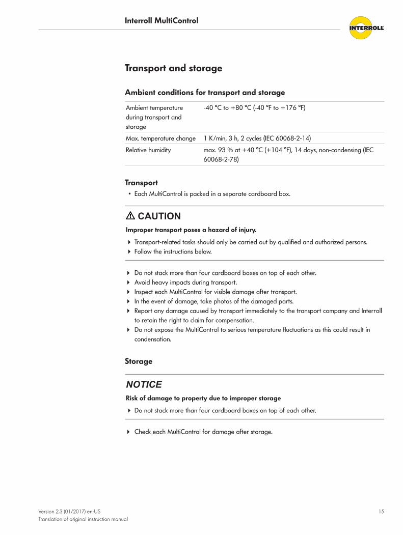
Ambient conditions for transport and storage
Ambient temperatureduring transport andstorage
-40 °C to +80 °C (-40 °F to +176 °F)
Max. temperature change 1 K/min, 3 h, 2 cycles (IEC 60068-2-14)
Relative humidity max. 93 % at +40 °C (+104 °F), 14 days, non-condensing (IEC60068-2-78)
Transport• Each MultiControl is packed in a separate cardboard box.
CAUTIONImproper transport poses a hazard of injury.
4 Transport-related tasks should only be carried out by qualified and authorized persons.4 Follow the instructions below.
4 Do not stack more than four cardboard boxes on top of each other.4 Avoid heavy impacts during transport.4 Inspect each MultiControl for visible damage after transport.4 In the event of damage, take photos of the damaged parts.4 Report any damage caused by transport immediately to the transport company and Interroll
to retain the right to claim for compensation.4 Do not expose the MultiControl to serious temperature fluctuations as this could result in
condensation.
Storage
NOTICERisk of damage to property due to improper storage
4 Do not stack more than four cardboard boxes on top of each other.
4 Check each MultiControl for damage after storage.

Interroll MultiControl
16 Version 2.3 (01/2017) en-USTranslation of original instruction manual
Assembly and installation
Warning information for assembly
NOTICERisk of damage leading to failure or shortened life expectancy
4 Check each MultiControl visually for damage before assembly.4 Make sure that the MultiControl is not warped during installation (no bending or torsion).4 Do not drill additional mounting holes in the casing or baseplate or enlarge the holes
provided.4 Do not drop the MultiControl to prevent internal damage.
Assembly of MultiControl
Initial assembly To fasten the MultiControl at the conveyor frame, the supplied baseplate must first be mountedon the conveyor frame. The baseplate features two sets of two holes for fastening theMultiControl. The left-hand holes should be used for initial assembly.
To simplify electrical installation, if possible all MultiControl should be assembled on the sameside of the conveyor. In the case of curves, wherever possible the MultiControl should beassembled on the outside radius as the RollerDrive connection is on this side.
The distance from the top edge of the MultiControl to neighboring components must be at least10 mm to be able to operate the magnetic sensor.
4 Identify a flat area on the conveyor system frame on which the MultiControl can beassembled. Ensure that there is approx. 25 mm space to the left of the designated area inorder to be able to move the MultiControl at a later date if necessary (see "Repeatedassembly", page 17).
4 Use the baseplate as a template and mark the center of both mounting holes. Pay attentionto the correct orientation of the baseplate (the labeling in the cable duct must be readable).
4 Drill two holes with a diameter of 6.5 mm on the markings in the conveyor frame.4 Screw the baseplate onto the conveyor using M6 screws.4 Ensure that the baseplate is not distorted.4 Insert flat cables for the voltage supply (see "Connect the power supply", page 19).

Interroll MultiControl
Assembly and installation
Version 2.3 (01/2017) en-USTranslation of original instruction manual
17
4 Place the MultiControl onto the left hole in each case and push it down until the lockingmechanism engages.
4 Fasten the MultiControl with the available screws in MultiControl and a Phillips screwdriveronto the baseplate according to DIN EN ISO 4857-Z2. Maximum tightening torque 2 Nm.This drives the contact pins through the flat cable and establishes contact with the voltagesupply.
To ensure a proper fastening of the MultiControl on the baseplate, only the screws supplied maybe used. If they are being damaged or lost, they can be reordered from Ejot using articlenumber 4280049809 (http://www.ejot.com).
Repeated assembly If an already connected MultiControl has to be removed from the backplane, the flat cable mustnot be reconnected at the same point as otherwise a proper contact cannot be ensured. Toavoid the flat cable having to be removed and repositioned on all MultiControl, in this case theMultiControl can be attached via the right-hand mounting hole in each case. Consequently, theposition of the MultiControl to the flat cable changes and the flat cable can be reconnected at adifferent point. The insulation is self-healing which means protection rating IP54 is achieved.
Interroll MultiControl
Assembly and installation
18 Version 2.3 (01/2017) en-USTranslation of original instruction manual
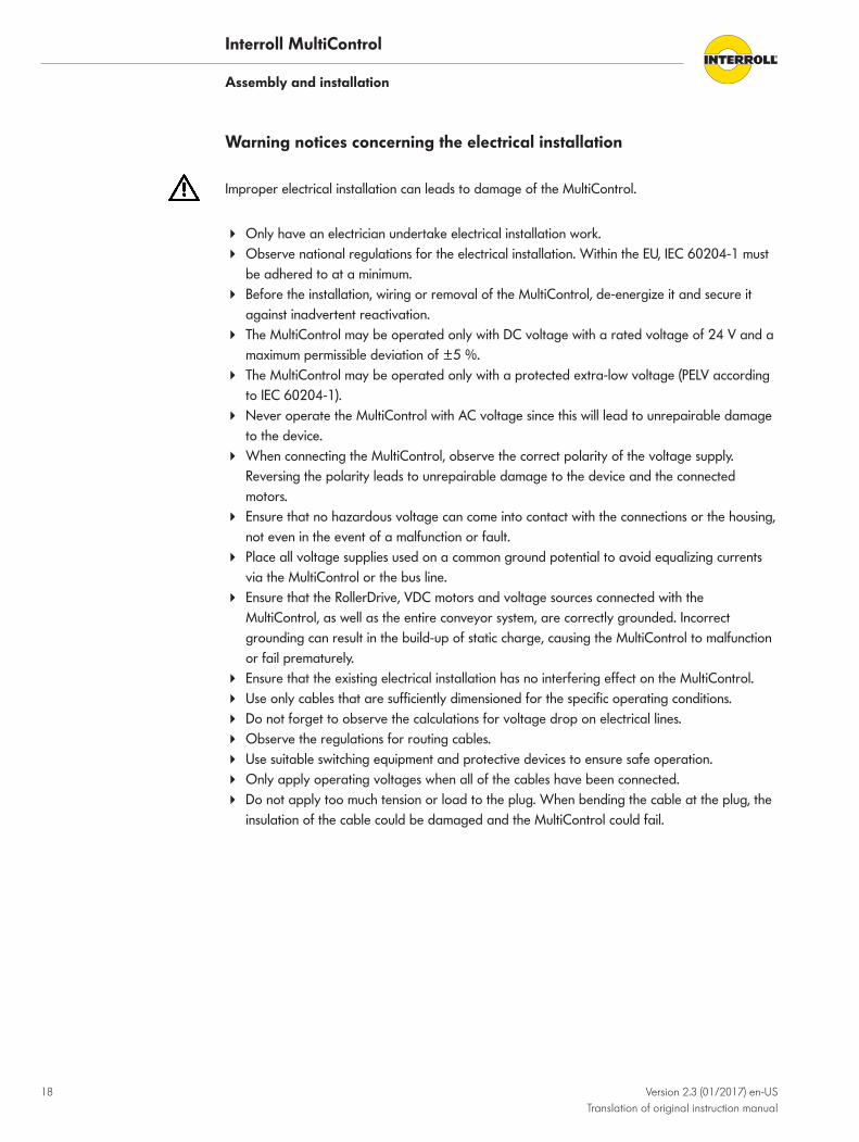
Warning notices concerning the electrical installation
Improper electrical installation can leads to damage of the MultiControl.
4 Only have an electrician undertake electrical installation work.4 Observe national regulations for the electrical installation. Within the EU, IEC 60204-1 must
be adhered to at a minimum.4 Before the installation, wiring or removal of the MultiControl, de-energize it and secure it
against inadvertent reactivation.4 The MultiControl may be operated only with DC voltage with a rated voltage of 24 V and a
maximum permissible deviation of ±5 %.4 The MultiControl may be operated only with a protected extra-low voltage (PELV according
to IEC 60204-1).4 Never operate the MultiControl with AC voltage since this will lead to unrepairable damage
to the device.4 When connecting the MultiControl, observe the correct polarity of the voltage supply.
Reversing the polarity leads to unrepairable damage to the device and the connectedmotors.
4 Ensure that no hazardous voltage can come into contact with the connections or the housing,not even in the event of a malfunction or fault.
4 Place all voltage supplies used on a common ground potential to avoid equalizing currentsvia the MultiControl or the bus line.
4 Ensure that the RollerDrive, VDC motors and voltage sources connected with theMultiControl, as well as the entire conveyor system, are correctly grounded. Incorrectgrounding can result in the build-up of static charge, causing the MultiControl to malfunctionor fail prematurely.
4 Ensure that the existing electrical installation has no interfering effect on the MultiControl.4 Use only cables that are sufficiently dimensioned for the specific operating conditions.4 Do not forget to observe the calculations for voltage drop on electrical lines.4 Observe the regulations for routing cables.4 Use suitable switching equipment and protective devices to ensure safe operation.4 Only apply operating voltages when all of the cables have been connected.4 Do not apply too much tension or load to the plug. When bending the cable at the plug, the
insulation of the cable could be damaged and the MultiControl could fail.

Interroll MultiControl
Assembly and installation
Version 2.3 (01/2017) en-USTranslation of original instruction manual
19
Electrical installation
Connect the power supply One or two flat cables of type 3G3G-FL with a core cross-section of 2 x 2.5 mm² are used forthe power supply:
• When using a flat cable, the MultiControl, the RollerDrive, the sensors and the logic aresupplied by the same voltage source.
• If two flat cables are used, the sensors and the logic are supplied with separate voltagesources. This allows the RollerDrive to be switched off without losing the bus communication.
The two ground potentials (L-) of the voltage supply are connected with each other in theMultiControl. The two positive contacts (L+) are connected with each other via a diode in theMultiControl. This ensures that the logic can also be supplied via the RollerDrive line, but not theRollerDrive via the logic supply.
4 Observe the national regulations for laying the flat cables. DIN EN 60204-1 applies inEurope.
4 Use only flat cables of type 3G3G-FL with a core cross-section of 2 x 2.5 mm².4 Insert the flat cable in the cable duct on the base plate in its correct orientation without
mechanical tension and without torsion. The cable ducts have a form-fit design (see graphic).As such, the flat cable can only be laid in one direction and polarity cannot be reversed.
12
34
2
1
1 Cable duct for RollerDrive voltage supplyPin at top: L+, brown core of line Pin at bottom: L-, blue core of line
2 Cable duct for logic and sensor system voltage supplyPin at top: L+, brown core of linePin at bottom: L-, blue core of line
4 If only one voltage supply is used, use the top cable duct with the label "PowerRollerDrive" (1). In this case, close the lower cable duct (2) with a stub to achieve protectionrating IP54.
4 If necessary take measures for strain relief or vibration reduction.4 Close the ends of the flat cables with end caps to achieve protection rating IP54.4 Install MultiControl on the base frame to establish the correct contact bonding (see "Initial
assembly", page 16).

Interroll MultiControl
Assembly and installation
20 Version 2.3 (01/2017) en-USTranslation of original instruction manual
4 Connect the line to the voltage source by connecting the brown core at L+ and the blue coreat L-.
If the MultiControl has to be removed after bonding, the flat cable must not be reconnected atthe same point as otherwise a proper contact cannot be ensured. In this case, the MultiControlhas to be repositioned (see "Repeated assembly", page 17).
NOTICEShort circuit from incorrect polarity
If the voltage supply is connected with incorrect polarity, it leads to a short circuit in the linebecause of the reverse polarity protection in the MultiControl.
4 Install a suitable protection mechanism so that the MultiControl and the line are notoverloaded.
4 Have an electrician undertake the dimensioning of the protection mechanism.4 When selecting the line protection, pay particular attention to the maximum short circuit
current of the voltage supply.
Connecting the RollerDrive The four connectors 'RD1' to 'RD4' are prepared for the RollerDrive EC310. The RollerDriveEC310 connection cable is already fitted with a suitable plug.
1
43
25
1 +24 V 4 Fault input2 Output for direction of rotation 5 Speed output3 Ground
4 Insert the plug so that the labeling EC310 on the plug points to the rear, i.e. it cannot beread.
4 Close unused RollerDrive connections with M8 dummy cap to achieve degree of protectionIP54.
NOTICEConnections are not short circuit-proof
In case of a short circuit, particularly between Pin 1 and Pin 3, the internal fuse in theMultiControl trips. The internal fuse cannot be replaced.
4 Ensure the correct polarity.

Interroll MultiControl
Assembly and installation
Version 2.3 (01/2017) en-USTranslation of original instruction manual
21
Connecting the bus The two connections 'Link A' and 'Link B' are suitable for M12 plugs, 4-pin, D-coded, pinassignment according to IEC 61076-2-101:
12
3 4
1
43
2
1 Transmission Data TD+ 3 Transmission Data TD-2 Receive Data RD+ 4 Receive Data RD-
The MultiControl is equipped with an integrated 2-port switch. This allows the MultiControl, e.g.to be integrated in line structures of the bus wiring.
4 Observe the installation guidelines of the respective bus systems:
• PROFINET: PROFIBUS & PROFINET International (PI), http://www.profibus.com• EtherCAT: EtherCAT Technology Group, http://www.ethercat.org• EtherNet/IP: ODVA, http://www.odva.org
4 If a connection remains unused, seal it with an M12 blind cap to achieve protection ratingIP54.

Interroll MultiControl
Assembly and installation
22 Version 2.3 (01/2017) en-USTranslation of original instruction manual
Connecting the sensors The connectors 'Sensor 1, I/O 1' to 'Sensor 4, I/O 4' can be used to connect four sensors andfour additional inputs and outputs (Aux I/O) to the MultiControl. PNP or NPN sensors as well assensors with opening or closing contacts can be used. The sensor type and the function of theadditional I/Os can be parameterized (see "Configuring inputs and outputs", page 29). The useof a Y-line allows connecting one sensor and one input/output to one connection at the sametime (see "Accessories", page 43).
2
13
4
Sensor connection
1 +24 VDC 3 Ground2 Aux I/O 4 Sensor input
NOTICEConnections are not short circuit-proof
In case of a short circuit, particularly between Pin 1 and Pin 3, the internal fuse in theMultiControl trips. The internal fuse cannot be replaced.
4 Ensure the correct polarity.
The inputs and outputs are not electrically isolated.
Parameters for the inputs
Input voltage 0 V to 24 V
Input resistance ≥ 15 kΩ
Switching thresholds ≥ 15 V "High" ≤ 5 V "Low"
Parameters for the outputs
Maximum output current ≤ 200 mA
Output voltage "1" with PNP > 15 V @ 200 mA
Output voltage "1" with NPN ≤ 5 V @ 200 mA
4 If a sensor connection remains unused, seal it with an M8 blind cap to achieve degree ofprotection IP54.

Interroll MultiControl
Version 2.3 (01/2017) en-USTranslation of original instruction manual
23
Initial startup and operation
Checks before initial startup4 Ensure that the base plate of the MultiControl is correctly fastened to the profile, that the
MultiControl is correctly fastened to the base plate, and that all screws are properlytightened.
4 Ensure that there are no additional areas of danger caused by interfaces to othercomponents.
4 Ensure that the wiring is in accordance with the specification and legal directives.4 Check all protection devices.4 Ensure there are no bystanders in dangerous areas around the conveyor.
Configuration optionsTo start up the MultiControl, it has to be configured first. There are several ways to achieve this:
• All settings can be configured using a web-based user interface on a computer connected tothe MultiControl (see "User interface", page 24).
• All settings, except for the bus type, can be configured using Service Data Objects (SDO)that are written by a master controller (see "Service Data Objects (SDO)", page 25).
• With the help of the magnetic sensor, the bus type and LED indicators can be configureddirectly on the MultiControl and the MultiControl can be tested, automatically configured orreset to factory settings (see "Magnetic sensor", page 25).
• With a PLC development environment, the station name, IP configuration and connectionsettings can be changed.
Interroll MultiControl
Initial startup and operation
24 Version 2.3 (01/2017) en-USTranslation of original instruction manual
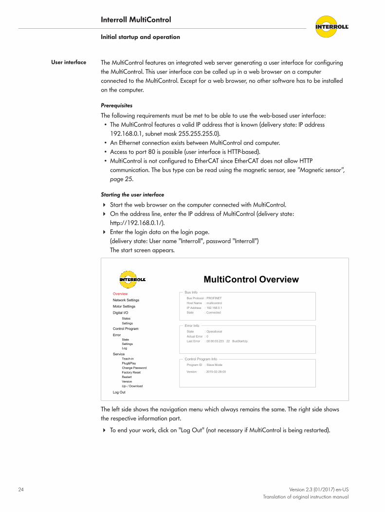
User interface The MultiControl features an integrated web server generating a user interface for configuringthe MultiControl. This user interface can be called up in a web browser on a computerconnected to the MultiControl. Except for a web browser, no other software has to be installedon the computer.
Prerequisites
The following requirements must be met to be able to use the web-based user interface:• The MultiControl features a valid IP address that is known (delivery state: IP address
192.168.0.1, subnet mask 255.255.255.0).• An Ethernet connection exists between MultiControl and computer.• Access to port 80 is possible (user interface is HTTP-based).• MultiControl is not configured to EtherCAT since EtherCAT does not allow HTTP
communication. The bus type can be read using the magnetic sensor, see "Magnetic sensor",page 25.
Starting the user interface
4 Start the web browser on the computer connected with MultiControl.4 On the address line, enter the IP address of MultiControl (delivery state:
http://192.168.0.1/).4 Enter the login data on the login page.
(delivery state: User name "Interroll", password "Interroll")The start screen appears.
MultiControl Overview
Overview
Network Settings
Motor Settings
Digital I/O
States
Settings
Control Program
Error
State
Settings
Log
Service
Teach-in
Plug&Play
Change Password
Factory Reset
Restart
Version
Up- / Download
Log Out
Bus Info
Bus Protocol : PROFINET
Host Name : multicontrol
IP Address : 192.168.0.1
State : Connected
Error Info
State : Operational
Actual Error : 0
Last Error : 00:00:03.223 22 BusStartUp
Control Program Info
Program ID : Slave Mode
Version : 2015-02-28-00
The left side shows the navigation menu which always remains the same. The right side showsthe respective information part.
4 To end your work, click on "Log Out" (not necessary if MultiControl is being restarted).

Interroll MultiControl
Initial startup and operation
Version 2.3 (01/2017) en-USTranslation of original instruction manual
25
Changing the password
4 In the "Service" menu, select the "Change Password" item.4 Enter the old password and then the new password twice.4 Click on "Submit" to confirm the change.
The user name cannot be changed.
Restarting MultiControl
MultiControl can be restarted via the user interface.
During the restart, the connection between MultiControl and computer/PLC is lost and has to bere-established afterwards.
4 In the "Service" menu, select the "Restart" item.4 Select "Yes" in the confirmation dialog and confirm with "Submit".
Exporting/importing the settings
The settings of MultiControl can be downloaded via the user interface and saved on a computer.If the MultiControl is replaced, the settings can be restored using the data backup.
4 In the "Service" menu, select the "Upload/Download" item.4 Save the desired file on the connected PC by right-clicking and selecting "Save as".
Service Data Objects(SDO)
Nearly all the settings of MultiControl (except for the bus type) can be changed via acycliccommunication. This communication corresponds to the Service Data Objects (SDO) of theCANopen protocol. Access can be established via the functions RDREC and WRREC inaccordance with IEC 61131-3.
The SDOs are divided into indexes and subindexes. During the configuration via EtherCATsystems, index and subindex are separated by a colon (e.g. index 0x4700, subindex A becomes0x4700:0A). For access via PROFINET and EtherNet/IP, index and subindex must be added (e.g.index 0x4700, subindex A becomes 0x470A).
Indexes of the individual functions see "Acyclical data", page 50.
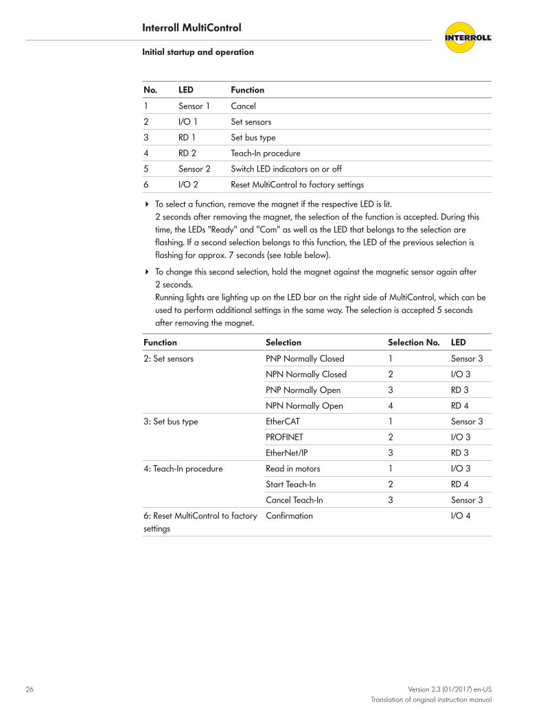
Magnetic sensor The following functions can be executed with the help of the magnetic sensor:• Set sensors• Set bus type• Perform Teach-In procedure• Switch LED indicators on or off• Reset MultiControl to factory settings
A magnet is required to operate the magnetic sensor (see "Accessories", page 43). Themagnetic sensor is located at the top side of MultiControl, between the two "Rs" of the"INTERROLL" label just in front of the rear plate (see "Structure", page 11).
4 Hold the magnet at the magnetic sensor.When the magnetic sensor recognizes the magnet, the "Fault" LED is permanently lit.After 1 second, running lights start on the LED bar on the left side of MultiControl. Every LEDis assigned a function (see table below).
Interroll MultiControl
Initial startup and operation
26 Version 2.3 (01/2017) en-USTranslation of original instruction manual
No. LED Function
1 Sensor 1 Cancel
2 I/O 1 Set sensors
3 RD 1 Set bus type
4 RD 2 Teach-In procedure
5 Sensor 2 Switch LED indicators on or off
6 I/O 2 Reset MultiControl to factory settings
4 To select a function, remove the magnet if the respective LED is lit.2 seconds after removing the magnet, the selection of the function is accepted. During thistime, the LEDs "Ready" and "Com" as well as the LED that belongs to the selection areflashing. If a second selection belongs to this function, the LED of the previous selection isflashing for approx. 7 seconds (see table below).
4 To change this second selection, hold the magnet against the magnetic sensor again after 2 seconds.Running lights are lighting up on the LED bar on the right side of MultiControl, which can beused to perform additional settings in the same way. The selection is accepted 5 secondsafter removing the magnet.
Function Selection Selection No. LED
2: Set sensors PNP Normally Closed 1 Sensor 3
NPN Normally Closed 2 I/O 3
PNP Normally Open 3 RD 3
NPN Normally Open 4 RD 4
3: Set bus type EtherCAT 1 Sensor 3
PROFINET 2 I/O 3
EtherNet/IP 3 RD 3
4: Teach-In procedure Read in motors 1 I/O 3
Start Teach-In 2 RD 4
Cancel Teach-In 3 Sensor 3
6: Reset MultiControl to factorysettings
Confirmation I/O 4

Interroll MultiControl
Initial startup and operation
Version 2.3 (01/2017) en-USTranslation of original instruction manual
27
LED indicators when using the magnetic sensor
When the magnetic sensor recognizes the magnet, the "Fault" LED is permanently lit. If thesetting via the magnetic sensor is activated, the LEDs "Ready" and "Com" are also flashing at1 Hz.
LED State Meaning
Sensor 1 On Function 1: Cancel
I/O 1 On Function 2: Set sensors
RD 1 On Function 3: Set bus type
RD 1 +Sensor 3
On Selection 1 for function 3: EtherCAT
RD 1 +I/O 3
On Selection 2 for function 3: PROFINET
RD 1 +RD 3
On Selection 3 for function 3: EtherNet/IP
RD 2 On Function 4: Teach-In procedure
Sensor 2 On Function 5: Switch LED indicators on or off
I/O 2 On Function 6: Reset MultiControl to factory settings
I/O 2 +I/O 4
On Confirmation for function 6: Reset MultiControl to factory settings
Sensor 3 Flashes 1 Hz Loading EtherCAT stack
I/O 3 Flashes 1 Hz Loading PROFINET stack
RD 3 Flashes 1 Hz Loading EtherNet/IP stack
Together with the following displays, the LEDs "Ready" and "Com" are flashing at 2 Hz, the"Fault" LED is off.
LED State Meaning
RD 1Sensor 3
OnFlashes 2 Hz
"EtherCAT" selection active, magnetic sensor not (any longer)actuated
RD 1I/O 3
OnFlashes 2 Hz
"PROFINET" selection active, magnetic sensor not (any longer)actuated
RD 1RD 3
OnFlashes 2 Hz
"EtherNet/IP" selection active, magnetic sensor not (any longer)actuated
I/O 2I/O 4
OnFlashes 2 Hz
Confirmation for function 6: Reset selected, magnetic sensor not(any longer) actuated

Interroll MultiControl
Initial startup and operation
28 Version 2.3 (01/2017) en-USTranslation of original instruction manual
Configuring MultiControl
Setting bus parameters Bus parameters may have to be changed for MultiControl to be integrated into an automationsystem. This includes the setting of the bus type used and an addressing.
MultiControl supports the following bus types:• PROFINET Conformance Class A• EtherNet/IP Object Class Adapter 0x64• EtherCAT
In its delivery state, MultiControl is set to PROFINET.
The following parameters can be changed for addressing MultiControl:• Configuration mode of the address:
– Static: The IP address is assigned by the user– I/O Controller: The IP address is assigned by the PLC– BOOTP: Bootstrap Protocol (procedure for assigning network parameters to a device
during startup, e.g. the IP address, only for EtherNet/IP)– DHCP: Dynamic Host Configuration Protocol (extension of BOOTP, only for EtherNet/IP)
• IP address and subnet mask• Gateway• Host name: If MultiControl is used with PROFINET, the unique PROFINET name must be
entered here.• ACD (EtherNet/IP function for recognizing address conflicts)• Domain name and DNS server• Neighbor Addresses (required only for ZPA and ZPA+ programs)• Big Endian format: Specification whether PLC data are in the big Endian format or not.
Configuration options:• User interface: "Network settings" menu• SDO: Indexes see "Bus parameters", page 52• Magnetic sensor (bus type only): Function 3 (LED "RD 1"), see "LED indicators when using the
magnetic sensor", page 27
For the changes to take effect, the MultiControl must subsequently be restarted.
NOTICEDestruction of MultiControl due to premature switch-off of the power supply
If the power supply is switched off while the bus type is being changed, it can destroy theMultiControl.
4 Ensure that the power supply is available without interruption while the bus type is beingchanged and until the restart is completed. Duration of the procedure approx. two minutes.
If the EtherCAT bus type is selected, the user interface can no longer be used after the restartsince this bus type is not supported.

Interroll MultiControl
Initial startup and operation
Version 2.3 (01/2017) en-USTranslation of original instruction manual
29
Selecting the applicationmodule
"I/O Device" must be selected here to operate the MultiControl as I/O device. The adjustabletimers 1 to 4 are without effect here and should not be adjusted.
When using the MultiControl with other internal programs, the corresponding program must beselected here , and the timers 1 to 4 be adjusted to the conveyor system.
Configuration options:• User interface: "Control Program" menu• SDO: Indexes see "Application module", page 55
Configuring inputs andoutputs
MultiControl has a total of eight inputs and outputs that are divided as follows:• Four inputs are assigned to sensor 1 to 4.• Four I/Os can be configured as additional inputs or outputs.
For all eight inputs and outputs, the type (PNP or NPN) and the logic (positive or negative) canbe defined. For the additional inputs and outputs, the function can also be defined (see "I/Oconfiguration", page 57).
Configuration options:• User interface: "Digital I/O" menu• SDO: Indexes see "Inputs and outputs", page 54
Defining the motor type For using the motor outputs, it must be specified whether the output should be used and whichmotor type will be connected. In the default setting, all outputs are configured for connecting aRollerDrive EC310.
The settings roller diameter, gear ratio, direction of rotation, speed, acceleration anddeceleration must be adjusted to the conveyor system.
Configuration options:• User interface: "Motor settings" menu• SDO: Indexes see "Motor settings", page 53
Switching off the LEDindicators
MultiControl provides the option of partially deactivating the LED indicators. This deactivates thedisplay of the switching states of inputs/outputs and the RollerDrive.
The status LEDs ("Power", "Ready", "Com" and "Fault") and the communication LEDs ("Link A"and "Link B") are not deactivated by the setting. A RollerDrive fault is also indicated by theflashing of the respective LED ("RD1" to "RD4").
Configuration options:• User interface• SDO: Indexes see "LED indicators", page 55• Magnetic sensor: Function 5 (LED "Sensor 2")
Defining the errorbehavior
MultiControl monitors several boundary conditions (such as voltages and temperature) and cangenerate error messages if the limits of these boundary conditions are violated. The errorbehavior can be configured.
The following error classes can be set for the error behavior:• 1 = Ignore: The error is ignored. As a result, it is not shown and not logged.• 2 = Warning: The error is indicated via the "Error” LED and logged.• 3 = Normal Stop: The error leads to an immediate shut-off of the motor.• 4 = Immediate Stop: The error leads to an immediate shut-off of the motor.
Interroll MultiControl
Initial startup and operation
30 Version 2.3 (01/2017) en-USTranslation of original instruction manual
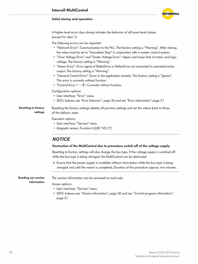
A higher-level error class always includes the behavior of all lower-level classes (except for class 1).
The following errors can be reported:• "Network Error": Communication to the PLC. The factory setting is "Warning". After startup,
the value must be set to "Immediate Stop" in conjunction with a master control system.• "Over Voltage Error" and "Under Voltage Error": Upper and lower limit of motor and logic
voltage. The factory setting is "Warning".• "Motor Error": Error signal of RollerDrive or RollerDrive not connected to activated motor
output. The factory setting is "Warning".• "General Control Error": Error in the application module. The factory setting is "Ignore".
This error is currently without function.• "Control Error 1 − 8": Currently without function.
Configuration options:• User interface: "Error" menu• SDO: Indexes see "Error behavior", page 56 and see "Error information", page 51
Resetting to factorysettings
Resetting the factory settings deletes all previous settings and set the values back to those of the delivery state.
Execution options:• User interface: "Service" menu• Magnetic sensor: Function 6 (LED "I/O 2")
NOTICEDestruction of the MultiControl due to premature switch-off of the voltage supply
Resetting to factory settings will also change the bus type. If the voltage supply is switched offwhile the bus type is being changed, the MultiControl can be destroyed.
4 Ensure that the power supply is available without interruption while the bus type is beingchanged and until the restart is completed. Duration of the procedure approx. two minutes.
Reading out versioninformation
The version information can be accessed as read-only.
Access options:• User interface: "Service" menu• SDO: Indexes see "Version information", page 50 and see "Control program information",
page 51

Interroll MultiControl
Initial startup and operation
Version 2.3 (01/2017) en-USTranslation of original instruction manual
31
Operation
CAUTIONAccidental start-up of the RollerDrive
Danger of crushing of limbs and damage to goods
4 Ensure that no persons are in the conveyor's danger areas before switching on the powersupply.
If the MultiControl functions as I/O device, it cannot independently start or stop motors orexecute other actions. To do so, it requires commands from a master controller, e.g. a PLC (see"Process data", page 32).
Pre-startup checks 4 Check all MultiControl for visible damage.4 Check all protection devices.4 Ensure that no RollerDrive connected to the MultiControl is blocked.4 Clearly specify and monitor the way goods are placed on the conveyor.4 Ensure there are no bystanders in dangerous areas around the conveyor.
Start 4 Ensure that the operating conditions are complied with during operation (see "Technicaldata", page 13).
4 Switch on the power supply.4 Send the corresponding signal to the MultiControl (see "Process data", page 32).
Stop Conveying stops in the following cases:• If the power supply is switched off.• If no signal for the start is present.• If an error from a corresponding error class is present (see "Defining the error behavior",
page 29).

Interroll MultiControl
Initial startup and operation
32 Version 2.3 (01/2017) en-USTranslation of original instruction manual
Process dataThe process data are divided into two parts: the process image of the inputs and the processimage of the outputs.
The addresses specified in this chapter are intended as offset to the start addresses specified inthe configuration of the PLC.
Explanation about the data types see "Data types", page 43.
Process image of theinputs
The process image of the inputs is divided into four parts: Sensors, Digital I/O, Motor Status andOthers.
Sensors
The information of the switching states of the sensors is located in the first BYTE of the processimage. The first four bits contain the physical state of the inputs Sensor 1 to 4, depending on theset PNP/NPN configuration and positive or negative polarity.
The inputs Sensor 5 to 8 are displayed only if the I/Os 1 to 4 are configured as additionalsensors.
Designation BYTE Bit Data type Comment
Sensor 1 0 0 BOOL Input "Sensor 1"
Sensor 2 0 1 BOOL Input "Sensor 2"
Sensor 3 0 2 BOOL Input "Sensor 3"
Sensor 4 0 3 BOOL Input "Sensor 4"
Sensor 5 0 4 BOOL Input "Sensor 5"
Sensor 6 0 5 BOOL Input "Sensor 6"
Sensor 7 0 6 BOOL Input "Sensor 7"
Sensor 8 0 7 BOOL Input "Sensor 8"
Digital I/O
The second BYTE contains the states of the digital I/Os. The value of the variables depends onthe PNP/NPN configuration and positive or negative polarity. If the I/O is used as output, thespecified switching state is also displayed here.
Designation BYTE Bit Data type Comment
I/O 1 1 0 BOOL Input "I/O 1"
I/O 2 1 1 BOOL Input "I/O 2"
I/O 3 1 2 BOOL Input "I/O 3"
I/O 4 1 3 BOOL Input "I/O 4"
Reserve 1 4 BOOL These four bits are currently not in use.
1 5 BOOL
1 6 BOOL
1 7 BOOL

Interroll MultiControl
Initial startup and operation
Version 2.3 (01/2017) en-USTranslation of original instruction manual
33
Motor status
Starting with the third BYTE, it contains the status values of the connected motors.
First, the error outputs of the connected motors are returned. In this case, a logical ONE at theinput means "Motor is Error state". To prevent unused motor connections from creating anyerrors, the connections should be deactivated, even if MultiControl is used as I/O device (see"Defining the motor type", page 29).
Second, the set values of the motors are output.
Third, the current consumptions of the motors are indicated.
Designation BYTE Bit Data type Comment
Motor error 1 2 0 BOOL Input motor error "RD 1"
Motor error 2 2 1 BOOL Input motor error "RD 2"
Motor error 3 2 2 BOOL Input motor error "RD 3"
Motor error 4 2 3 BOOL Input motor error "RD 4"
Reserve 2 4 BOOL These four bits are currently not in use.
2 5 BOOL
2 6 BOOL
2 7 BOOL
Speed 1 3 SINT [%], speed setpoint motor 1
Speed 2 4 SINT [%], speed setpoint motor 2
Speed 3 5 SINT [%], speed setpoint motor 3
Speed 4 6 SINT [%], speed setpoint motor 4
Reserve 7 BYTE This BYTE is currently not in use.
Motor current 1 8 INT [mA] motor current motor 1
Motor current 2 10 INT [mA] motor current motor 2
Motor current 3 12 INT [mA] motor current motor 3
Motor current 4 14 INT [mA] motor current motor 4
Interroll MultiControl
Initial startup and operation
34 Version 2.3 (01/2017) en-USTranslation of original instruction manual
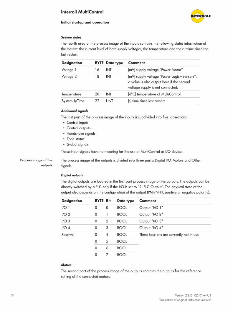
System status
The fourth area of the process image of the inputs contains the following status information ofthe system: the current level of both supply voltages, the temperature and the runtime since thelast restart.
Designation BYTE Data type Comment
Voltage 1 16 INT [mV] supply voltage "Power Motor"
Voltage 2 18 INT [mV] supply voltage "Power Logic+Sensors",a value is also output here if the secondvoltage supply is not connected.
Temperature 20 INT [d°C] temperature of MultiControl
SystemUpTime 22 LINT [s] time since last restart
Additional signals
The last part of the process image of the inputs is subdivided into five subsections:• Control inputs• Control outputs• Handshake signals• Zone status• Global signals
These input signals have no meaning for the use of MultiControl as I/O device.
Process image of theoutputs
The process image of the outputs is divided into three parts: Digital I/O, Motors and Othersignals.
Digital outputs
The digital outputs are located in the first part process image of the outputs. The outputs can bedirectly switched by a PLC only if the I/O is set to "2: PLC-Output". The physical state at theoutput also depends on the configuration of the output (PNP/NPN, positive or negative polarity).
Designation BYTE Bit Data type Comment
I/O 1 0 0 BOOL Output "I/O 1"
I/O 2 0 1 BOOL Output "I/O 2"
I/O 3 0 2 BOOL Output "I/O 3"
I/O 4 0 3 BOOL Output "I/O 4"
Reserve 0 4 BOOL These four bits are currently not in use.
0 5 BOOL
0 6 BOOL
0 7 BOOL
Motors
The second part of the process image of the outputs contains the outputs for the referencesetting of the connected motors.

Interroll MultiControl
Initial startup and operation
Version 2.3 (01/2017) en-USTranslation of original instruction manual
35
Designation BYTE Bit Data type Comment
Speed 1 1 SINT [%], speed setpoint motor 1
Speed 2 2 SINT [%], speed setpoint motor 2
Speed 3 3 SINT [%], speed setpoint motor 3
Speed 4 4 SINT [%], speed setpoint motor 4
The speed of the connected RollerDrive depends on the gear ratio.
4 To set the speed, switch a percentage value between 5 and 100 according to the tablebelow to the "Speed" output at the "RD" connection of MultiControl. (Values not listed can beinterpolated in a linear way.)
4 To reverse the direction of rotation, use negative values between -5 and -100.
Speed output at the "RD"connection
Speed at gear ratio [m/s]
9:1 12:1 16:1 20:1 24:1 36:1 48:1 64:1 96:1
0 0.00 0.00 0.00 0.00 0.00 0.00 0.00 0.00 0.00
5 0.09 0.07 0.05 0.04 0.03 0.02 0.02 0.01 0.01
10 0.17 0.13 0.10 0.08 0.07 0.04 0.03 0.02 0.02
15 0.26 0.20 0.15 0.12 0.10 0.07 0.05 0.04 0.02
20 0.35 0.26 0.20 0.16 0.13 0.09 0.07 0.05 0.03
25 0.44 0.33 0.25 0.20 0.16 0.11 0.08 0.06 0.04
30 0.52 0.39 0.29 0.24 0.20 0.13 0.10 0.07 0.05
35 0.61 0.46 0.34 0.27 0.23 0.15 0.11 0.09 0.06
40 0.70 0.52 0.39 0.31 0.26 0.17 0.13 0.10 0.07
45 0.79 0.59 0.44 0.35 0.29 0.20 0.15 0.11 0.07
50 0.87 0.65 0.49 0.39 0.33 0.22 0.16 0.12 0.08
55 0.96 0.72 0.54 0.43 0.36 0.24 0.18 0.13 0.09
60 1.05 0.79 0.59 0.47 0.39 0.26 0.20 0.15 0.10
65 1.13 0.85 0.64 0.51 0.43 0.28 0.21 0.16 0.11
70 1.22 0.92 0.69 0.55 0.46 0.31 0.23 0.17 0.11
75 1.31 0.98 0.74 0.59 0.49 0.33 0.25 0.18 0.12
80 1.40 1.05 0.79 0.63 0.52 0.35 0.26 0.20 0.13
85 1.48 1.11 0.83 0.67 0.56 0.37 0.28 0.21 0.14
90 1.57 1.18 0.88 0.71 0.59 0.39 0.29 0.22 0.15
95 1.66 1.24 0.93 0.75 0.62 0.41 0.31 0.23 0.16
100 1.75 1.31 0.98 0.79 0.65 0.44 0.33 0.25 0.16

Interroll MultiControl
Initial startup and operation
36 Version 2.3 (01/2017) en-USTranslation of original instruction manual
Additional signals
The last part of the process image of the outputs is subdivided into three subsections:• Control inputs overwrite• Control outputs overwrite• Handshake signals overwrite

Interroll MultiControl
Version 2.3 (01/2017) en-USTranslation of original instruction manual
37
Maintenance and cleaning
Warning notices concerning maintenance and cleaning
CAUTIONRisk of injuries due to incorrect handling
4 Maintenance work and cleaning must only be performed by qualified and authorizedpersons.
4 Perform maintenance work only after switching off the power. Ensure that the MultiControlcannot be turned on accidentally.
4 Set up signs indicating that maintenance work is in progress.
Maintenance
Checking MultiControl The MultiControl itself is maintenance-free. For avoidance of faults however, regular inspectionof the connections and fixings is recommended.
4 As part of the regular control and maintenance work on the conveyor, ensure that the screwsof the MultiControl are still tight and that the cables are still laid properly and connected tothe terminals.
Replacing MultiControl If a MultiControl is damaged, it has to be replaced.
4 Install a new MultiControl (see "Shutdown", page 38 and see "Assembly and installation",page 16).
4 Configure a new MultiControl (see "Initial startup and operation", page 23).
CleaningDust and dirt in combination with humidity may bridge the electric circuit. Therefore, in a dirtyenvironment, periodic cleaning will help to avoid short-circuits which could damage theMultiControl.
NOTICERisk of damage to the MultiControl due to incorrect cleaning
4 Do not immerse the MultiControl in liquids.
4 Clean away dust and soiling if necessary.4 For more thorough cleaning, disconnect the MultiControl from the power supply, remove it,
and wipe over it with a damp cloth.

Interroll MultiControl
38 Version 2.3 (01/2017) en-USTranslation of original instruction manual
Decommissioning and disposal
Shutdown
CAUTIONRisk of injury due to incorrect handling
4 Shut-down may only be executed by qualified and authorized persons.4 Shut down MultiControl only in de-energized state. Secure MultiControl against inadvertent
activation.
4 Disconnect all cables from the MultiControl.4 Loosen the screws with which the MultiControl is fastened to the base plate and pull off
MultiControl.4 If the MultiControl is to be completely disassembled, also loosen the screws with which the
base plate is fastened to the conveyor frame and remove the base plate from the conveyorframe.
DisposalThe operator is responsible for the proper disposal of the MultiControl.
4 In doing so, industry-specific and local provisions must be observed for the disposal of theMultiControl and its packaging.
4 The packaging must be recycled to provide environmental relief.

Interroll MultiControl
Version 2.3 (01/2017) en-USTranslation of original instruction manual
39
Troubleshooting
Meaning of the LEDsLEDs on the MultiControl inform about the operating state of the conveyor.
Status descriptions of the LEDs:• Off: LED is permanently off• On: LED is permanently on• Flashes 1 Hz: LED flashes at a frequency of 1 Hz; pulse duty factor 1:1• Flashes 2 Hz: LED flashes at a frequency of 2 Hz; pulse duty factor 1:1• −: LED state is variable
General LEDs Power Ready Com Fault Meaning Priority
On On On Off Operational, no error
− On Flashes1 Hz
Off Bus startup mode: After starting, a wait time ofup to 30 s for establishing the connection tothe PLC is in place.
− − − Flashes 1 x Error in application program, e.g. timeout 1
− − − Flashes 2 x Communication fault: Connection is notestablished within 30 s after starting orconnection to PLC is lost. Error acknowledgesitself automatically.
3
− − − Flashes 3 x RollerDrive error: Defective RollerDrive isindicated by flashing of the respective "RD"LED.
2
Off On − Flashes 4 x Voltage supply for motors is missing. 5
− − − Flashes 5 x Voltage error in undervoltage 4
− − − Flashes 6 x Voltage error in overvoltage 4
− − − Flashes 7 x Temperature in MultiControl too high. 6
− − − Flashes 8 x Overload protection of brake chopper resistoractive.
7
− − − Flashes 9 x Handshake communication malfunctioning. Seeinstructions for ZPA and ZPA+ applications.
− − − Flashes 10 x
No connection to the neighbor. Seeinstructions for ZPA and ZPA+ applications.
If several errors occur at the same time. only the error with the highest priority is displayed.
Removal of errors see "Error messages", page 41.

Interroll MultiControl
Troubleshooting
40 Version 2.3 (01/2017) en-USTranslation of original instruction manual
LEDs of connections LED State Meaning
Sensor 1Sensor 2Sensor 3Sensor 4
On Logical switching state of displayed sensor:Positive logic configured and logical "1" (PNP 24 V, NPN 0 V) atinput - or -Negative logic configured and logical "0" at input
I/O 1I/O 2I/O 3I/O 4
On Logical switching state of displayed input/output:Positive logic configured and logical "1" (PNP 24 V, NPN 0 V) atinput - or -Negative logic configured and logical "0" at input
RD 1RD 2RD 3RD 4
On Displayed RollerDrive receives nominal value
Link ALink B
On or flashing (for EtherCatbus type)
Displayed network connection is OK

Interroll MultiControl
Troubleshooting
Version 2.3 (01/2017) en-USTranslation of original instruction manual
41
TroubleshootingThe MultiControl is a complex system. There are many interactions between all systemcomponents. Naturally, errors can occur in such a system which either result from the conveyingprocesses or the interaction between the individual components. Not all errors can be shown indetail and the error location and display location cannot always be allocated to each other. A better error diagnostics is possible via the PLC.
It troubleshooting is not successful, please contact Interroll support and have the followinginformation at hand:
• Serial number of the affected MultiControl.• Details of the configuration• Details of the LED displays• Details of the error codes
Error messages
Error message Possible cause Remedy
Communication fault Connection to the PLC is malfunctioning 4Check bus wiring.4 Check bus type.4 Check network address and bus name.
RollerDrive error Error signal of RollerDrive or RollerDrive notconnected to activated motor output
4Check motor configuration.4 Ensure that all RollerDrive are correctly
connected.4 Check for malfunctions according to the
RollerDrive operating instructions.
Voltage supply for motors is missing
4Check supply voltage. (Is emergency stop activated?)
Undervoltage Voltage supply is below 19 V 4Ensure that the supply voltage is above22.8 V.
Overvoltage Voltage supply is above 25.2 V 4Ensure that the supply voltage is below25.2 V.

Interroll MultiControl
Troubleshooting
42 Version 2.3 (01/2017) en-USTranslation of original instruction manual
Additional faults
Fault Possible cause Remedy
The MultiControl is notworking or is workingincorrectly
No or insufficient power supply 4Check whether the output voltage of thepower supply is within the specified voltagerange.
4 Check the connections and correct ifnecessary.
The MultiControl is defectiveor damaged
Internal fuse triggered or faulty. 4Replace the MultiControl.
RollerDrive does not rotate RollerDrive not or not correctly inserted orRollerDrive defective
4Check whether the power supply is within thespecified voltage range.
4 Check the connections and correct ifnecessary.
4 Replace the RollerDrive if necessary.
Brake chopper overheats: The applicationfeeds back too much energy or the voltagesupply is too high
4Allow to cool down.4 Lower ambient temperature if necessary.4 Check voltage supply and set to 24 V if
necessary.

Interroll MultiControl
Version 2.3 (01/2017) en-USTranslation of original instruction manual
43
Appendix
Accessories
Designation Reference number
Cable bridge S-1004028
Flat cable for voltage (3G3G-FL, 2 x 2.5 mm², black, 25-m sections)
S-1004030
400-V power supply S-1004029
Magnetic key S-64100210
Y-line 3-pin S-1104439
Y-line 4-pin S-1104460
EtherNet line M12/M12 (3 m) S-1104438
MultiControl enclosure:1 x M12 dummy plug3 x M8 Snap-in dummy plug3 x M8 screw connection dummy plug
S-1104466
Extension cable for RollerDrive EC310, (2 m) S-1004033
Data typesThe following data types are used for cyclical and acyclical communication with the MultiControl:
Abbreviation
Data type Description
BOOL Boolean Truth value (true/false)
BYTE Byte Bit sequence with 8 bits
SINT Short Integer Integer variable with 8 bit
USINT Unsigned Short Integer Positive integer variable with 8 bit
INT Integer Integer variable with 16 bit
UINT Unsigned Integer Positive integer variable with 16 bit
DINT Double Integer Integer variable with 32 bit
UDINT Unsigned Double Integer Positive integer variable with 32 bit
LINT Long Integer Integer variable with 64 bit
STRING String Character string with up to 31 characters

Interroll MultiControl
Appendix
44 Version 2.3 (01/2017) en-USTranslation of original instruction manual
Cyclical process image
Input
No. Category Byte Bit Designation Type Comment
1 Sensors 0 .0 Sensor 1 BOOL Status at "Sensor 1" input High/Low = Sensor blocked / not blocked; logicalstatus, voltage level depends on configuration(NPN/PNP; polarity)
2 Sensors 0 .1 Sensor 2 BOOL Status at input "Sensor 2", see above
3 Sensors 0 .2 Sensor 3 BOOL Status at input "Sensor 3", see above
4 Sensors 0 .3 Sensor 4 BOOL Status at input "Sensor 4", see above
5 Sensors 0 .4 Sensor 5 BOOL Input dependent on configuration, e.g. "Aux 1" configured as sensor 5
6 Sensors 0 .5 Sensor 6 BOOL
7 Sensors 0 .6 Sensor 7 BOOL
8 Sensors 0 .7 Sensor 8 BOOL
9 Digital I/Os 1 .0 IO 1 BOOL Logical state, voltage level depends onconfiguration (NPN/PNP; polarity)
10 Digital I/Os 1 .1 IO 2 BOOL
11 Digital I/Os 1 .2 IO 3 BOOL
12 Digital I/Os 1 .3 IO 4 BOOL
13 Digital I/Os 1 .4 Reserve BOOL Not used
14 Digital I/Os 1 .5 Reserve BOOL Not used
15 Digital I/Os 1 .6 Reserve BOOL Not used
16 Digital I/Os 1 .7 Reserve BOOL Not used
17 MotorStates 2 .0 Error Motor 1 BOOL High = motor error, Low = motor OK
18 MotorStates 2 .1 Error Motor 2 BOOL
19 MotorStates 2 .2 Error Motor 3 BOOL
20 MotorStates 2 .3 Error Motor 4 BOOL
21 MotorStates 2 .4 Reserve BOOL Not used
22 MotorStates 2 .5 Reserve BOOL Not used
23 MotorStates 2 .6 Reserve BOOL Not used
24 MotorStates 2 .7 Reserve BOOL Not used
25 MotorStates 3 Speed Motor 1 SINT Speed 0...100 (0 = stop, 100 = max. speed),negative values indicate reversed direction ofrotation
26 MotorStates 4 Speed Motor 2 SINT
27 MotorStates 5 Speed Motor 3 SINT
28 MotorStates 6 Speed Motor 4 SINT
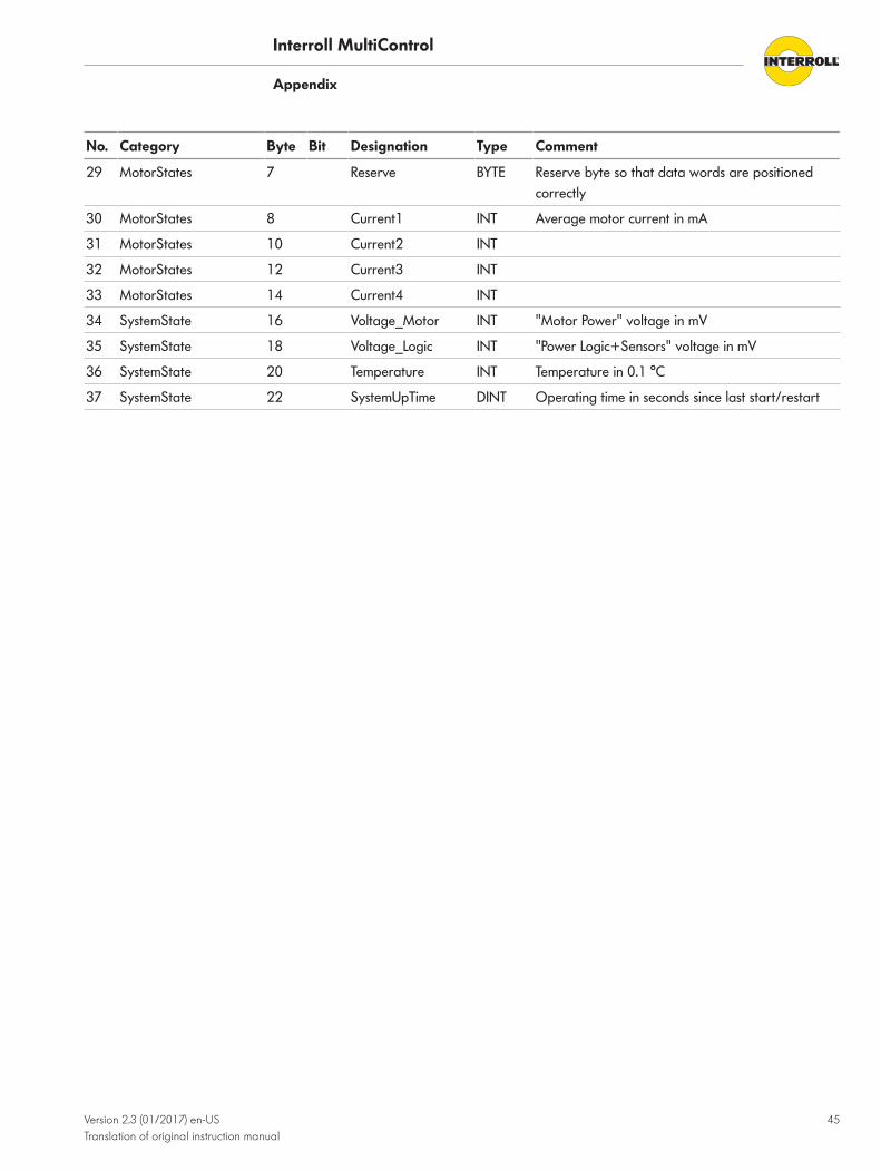
Interroll MultiControl
Appendix
Version 2.3 (01/2017) en-USTranslation of original instruction manual
45
No. Category Byte Bit Designation Type Comment
29 MotorStates 7 Reserve BYTE Reserve byte so that data words are positionedcorrectly
30 MotorStates 8 Current1 INT Average motor current in mA
31 MotorStates 10 Current2 INT
32 MotorStates 12 Current3 INT
33 MotorStates 14 Current4 INT
34 SystemState 16 Voltage_Motor INT "Motor Power" voltage in mV
35 SystemState 18 Voltage_Logic INT "Power Logic+Sensors" voltage in mV
36 SystemState 20 Temperature INT Temperature in 0.1 °C
37 SystemState 22 SystemUpTime DINT Operating time in seconds since last start/restart
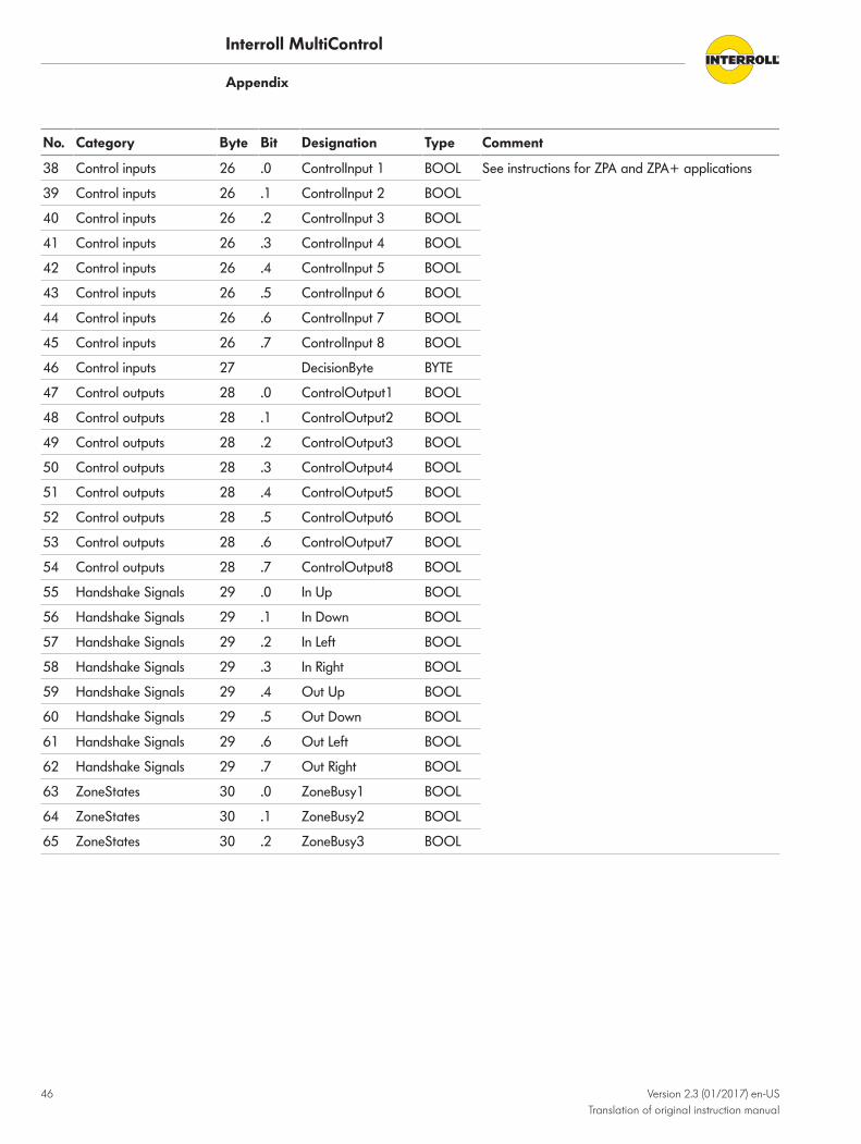
Interroll MultiControl
Appendix
46 Version 2.3 (01/2017) en-USTranslation of original instruction manual
No. Category Byte Bit Designation Type Comment
38 Control inputs 26 .0 ControlInput 1 BOOL See instructions for ZPA and ZPA+ applications
39 Control inputs 26 .1 ControlInput 2 BOOL
40 Control inputs 26 .2 ControlInput 3 BOOL
41 Control inputs 26 .3 ControlInput 4 BOOL
42 Control inputs 26 .4 ControlInput 5 BOOL
43 Control inputs 26 .5 ControlInput 6 BOOL
44 Control inputs 26 .6 ControlInput 7 BOOL
45 Control inputs 26 .7 ControlInput 8 BOOL
46 Control inputs 27 DecisionByte BYTE
47 Control outputs 28 .0 ControlOutput1 BOOL
48 Control outputs 28 .1 ControlOutput2 BOOL
49 Control outputs 28 .2 ControlOutput3 BOOL
50 Control outputs 28 .3 ControlOutput4 BOOL
51 Control outputs 28 .4 ControlOutput5 BOOL
52 Control outputs 28 .5 ControlOutput6 BOOL
53 Control outputs 28 .6 ControlOutput7 BOOL
54 Control outputs 28 .7 ControlOutput8 BOOL
55 Handshake Signals 29 .0 In Up BOOL
56 Handshake Signals 29 .1 In Down BOOL
57 Handshake Signals 29 .2 In Left BOOL
58 Handshake Signals 29 .3 In Right BOOL
59 Handshake Signals 29 .4 Out Up BOOL
60 Handshake Signals 29 .5 Out Down BOOL
61 Handshake Signals 29 .6 Out Left BOOL
62 Handshake Signals 29 .7 Out Right BOOL
63 ZoneStates 30 .0 ZoneBusy1 BOOL
64 ZoneStates 30 .1 ZoneBusy2 BOOL
65 ZoneStates 30 .2 ZoneBusy3 BOOL

Interroll MultiControl
Appendix
Version 2.3 (01/2017) en-USTranslation of original instruction manual
47
No. Category Byte Bit Designation Type Comment
66 ZoneStates 30 .3 ZoneBusy4 BOOL See instructions for ZPA and ZPA+ applications
67 ZoneStates 30 .4 Reserve BOOL
68 ZoneStates 30 .5 Reserve BOOL
69 ZoneStates 30 .6 Reserve BOOL
70 ZoneStates 30 .7 Reserve BOOL
71 ZoneStates 31 ZoneError1 BYTE
72 ZoneStates 32 ZoneError2 BYTE
73 ZoneStates 33 ZoneError3 BYTE
74 ZoneStates 34 ZoneError4 BYTE
75 Global Signals 35 .0 Reserve BOOL
76 Global Signals 35 .1 Reserve BOOL
77 Global Signals 35 .2 Reserve BOOL
78 Global Signals 35 .3 Reserve BOOL
79 Global Signals 35 .4 Reserve BOOL
80 Global Signals 35 .5 Reserve BOOL
81 Global Signals 35 .6 Reserve BOOL
82 Global Signals 35 .7 Reserve BOOL

Interroll MultiControl
Appendix
48 Version 2.3 (01/2017) en-USTranslation of original instruction manual
Output
No. Category Byte Bit Designation Type Comment
1 Digital outputs 0 .0 PLC Output1 BOOL Logical state, voltage level depends on I/Oconfiguration (NPN/PNP type; polarity)
2 Digital outputs 0 .1 PLC Output2 BOOL
3 Digital outputs 0 .2 PLC Output3 BOOL
4 Digital outputs 0 .3 PLC Output4 BOOL
5 Digital outputs 0 .4 Reserve BOOL
6 Digital outputs 0 .5 Reserve BOOL
7 Digital outputs 0 .6 Reserve BOOL
8 Digital outputs 0 .7 Reserve BOOL
9 Motor 1 Speed1 SINT Speed 0...100 (0 = stop, 100 = max. speed),negative values indicate reversed direction ofrotation
10 Motor 2 Speed2 SINT
11 Motor 3 Speed3 SINT
12 Motor 4 Speed4 SINT
13 Control inputs overwrite 5 .0 ControlInput1 BOOL See instructions for ZPA and ZPA+ applications
14 Control inputs overwrite 5 .1 ControlInput2 BOOL
15 Control inputs overwrite 5 .2 ControlInput3 BOOL
16 Control inputs overwrite 5 .3 ControlInput4 BOOL
17 Control inputs overwrite 5 .4 ControlInput5 BOOL
18 Control inputs overwrite 5 .5 ControlInput6 BOOL
19 Control inputs overwrite 5 .6 ControlInput7 BOOL
20 Control inputs overwrite 5 .7 ControlInput8 BOOL
21 Control inputs overwrite 6 DecisionInput BYTE
22 Control outputs overwrite 7 .0 ControlOutput1 BOOL
23 Control outputs overwrite 7 .1 ControlOutput2 BOOL
24 Control outputs overwrite 7 .2 ControlOutput3 BOOL
25 Control outputs overwrite 7 .3 ControlOutput4 BOOL
26 Control outputs overwrite 7 .4 ControlOutput5 BOOL
27 Control outputs overwrite 7 .5 ControlOutput6 BOOL
28 Control outputs overwrite 7 .6 ControlOutput7 BOOL
29 Control outputs overwrite 7 .7 ControlOutput8 BOOL
30 Handshake Signals Overwrite 8 .0 In Up BOOL
31 Handshake Signals Overwrite 8 .1 In Down BOOL
32 Handshake Signals Overwrite 8 .2 In Left BOOL
33 Handshake Signals Overwrite 8 .3 In Right BOOL
34 Handshake Signals Overwrite 8 .4 Out Up BOOL

Interroll MultiControl
Appendix
Version 2.3 (01/2017) en-USTranslation of original instruction manual
49
No. Category Byte Bit Designation Type Comment
35 Handshake Signals Overwrite 8 .5 Out Down BOOL See instructions for ZPA and ZPA+ applications
36 Handshake Signals Overwrite 8 .6 Out Left BOOL
37 Handshake Signals Overwrite 8 .7 Out Right BOOL
38 Global Signals 9 .0 Reserve BOOL
39 Global Signals 9 .1 Reserve BOOL
40 Global Signals 9 .2 Reserve BOOL
41 Global Signals 9 .3 Reserve BOOL
42 Global Signals 9 .4 Reserve BOOL
43 Global Signals 9 .5 Reserve BOOL
44 Global Signals 9 .6 Reserve BOOL
45 Global Signals 9 .7 Reserve BOOL

Interroll MultiControl
Appendix
50 Version 2.3 (01/2017) en-USTranslation of original instruction manual
Acyclical dataThe SDOs are divided into indexes and subindexes. During the configuration via EtherCATsystems, index and subindex are separated by a colon (e.g. index 0x4700, subindex A becomes0x4700:0A). For access via PROFINET and EtherNet/IP, index and subindex must be added (e.g. index 0x4700, subindex A becomes 0x470A).
Version information SDO index: 0x4000
Subindex Designation Data type Access Comment
1 Hardware STRING R
2 Application Software STRING R
3 System Software STRING R
4 Network Software STRING R
Manufacturer information SDO index: 0x4100
Subindex Designation Data type Access Comment
1 Serial Number STRING R
2 Manufacture Date STRING R
Diagnostic information SDO index: 0x4200
Subindex Designation Data type Access Comment
1 Motor voltage act. [mV] INT R Effective motor supply voltage
2 Motor voltage max. [mV] INT R Maximum motor supply voltage
3 Motor voltage min. [mV] INT R Minimum motor supply voltage
4 Logic voltage act. [mV] INT R Effective logic supply voltage
5 Logic voltage max. [mV] INT R Maximum logic supply voltage
6 Logic voltage min. [mV] INT R Minimum logic supply voltage
7 Temperature act. [d°C] INT R Effective temperature
8 Temperature max. [d°C] INT R Maximum temperature
9 Temperature min. [d°C] INT R Minimum temperature

Interroll MultiControl
Appendix
Version 2.3 (01/2017) en-USTranslation of original instruction manual
51
Error information SDO index: 0x4300
Subindex Designation Data type Access Comment
1 Error State BYTE R 1 = operating2 = minor error3 = severe error
2 Error Code UINT R Error number of last error (0 = no error)
3 Time Motor Error 1 UDINT R Time since last error from motor 1
4 Time Motor Error 2 UDINT R Time since last error from motor 2
5 Time Motor Error 3 UDINT R Time since last error from motor 3
6 Time Motor Error 4 UDINT R Time since last error from motor 4
Network online time SDO index: 0x4400
Subindex Designation Data type Access Comment
0 Network Online Time UDINT R Operating time of bus
Control programinformation
SDO index: 0x4500
Subindex Designation Data type Access Comment
1 Selected State Table UINT R Selected application program
2 Version Year UINT R Version of application program
3 Version Month USINT R
4 Version Day USINT R
5 Version Hour USINT R
6 IO 1 Usage BYTE R IO 1 is used in the selected application program
7 IO 2 Usage BYTE R IO 2 is used in the selected application program
8 IO 3 Usage BYTE R IO 3 is used in the selected application program
9 IO 4 Usage BYTE R IO 4 is used in the selected application program

Interroll MultiControl
Appendix
52 Version 2.3 (01/2017) en-USTranslation of original instruction manual
Bus parameters SDO index: 0x4600
Subindex Designation Data type Access Comment
1 Bus Type USINT R Bus type used: 1 = EtherCAT 2 = PROFINET 3 = EtherNet/IP
2 IP Configuration Mode USINT R/W Configuration mode of the address: 1 = Static2 = BOOTP3 = DHCP
3 IP Address UDINT R/W Own IP address
4 IP Network Mask UDINT R/W Subnet mask
5 IP Gateway Address UDINT R/W IP Address Default Gateway
6 IP Address DNS 1 UDINT R/W IP Address Domain Name Server #1
7 IP Address DNS 2 UDINT R/W IP Address Domain Name Server #2
8 IP Host Name STRING R/W IP Host Name
9 IP Domain Name STRING R/W IP Domain Name
A ACD Enable BOOL R/W Recognition of address conflicts (EtherNet/IP)
B Quick Startup Enable BOOL R/W Quickstart (PROFINET)
C IP Address Neighbor 1 UDINT R/W IP address of neighbors when using ZPA and ZPA+.
D IP Address Neighbor 2 UDINT R/W
S IP Address Neighbor 3 UDINT R/W
F IP Address Neighbor 4 UDINT R/W
10 IP Address Neighbor 5 UDINT R/W
11 IP Address Neighbor 6 UDINT R/W
12 IP Address Neighbor 7 UDINT R/W
13 IP Address Neighbor 8 UDINT R/W
14 Big Endian format: BOOL R/W PLC data are in big endian format (MSB first)

Interroll MultiControl
Appendix
Version 2.3 (01/2017) en-USTranslation of original instruction manual
53
Motor settings SDO index: 0x4700
The settings of subindexes 5 to 32 are currently without effect. The speed and direction ofrotation can be set via cyclical process data (see "Process image of the outputs", page 34).
Subindex Designation Data type Access Comment Min. Max.
1 Motor Type 1 USINT R/W Motor type to connection RD1:0 = None1 = EC3102 = VDC_SPEED 3 = VDC_POSITIONSetting 2 and are currently not being supported.
0 3
2 Motor Type 2 USINT R/W Motor type to connection RD2Values see above
0 3
3 Motor Type 3 USINT R/W Motor type to connection RD3Values see above
0 3
4 Motor Type 4 USINT R/W Motor type to connection RD4Values see above
0 3
5 Direction CW 1 BOOL R/W TRUE = RollerDrive 1 turns clockwise FALSE = RollerDrive 1 turns counterclockwise
6 Direction CW 2 BOOL R/W TRUE = RollerDrive 2 turns clockwiseFALSE = RollerDrive 1 turns counterclockwise
7 Direction CW 3 BOOL R/W TRUE = RollerDrive 3 turns clockwiseFALSE = RollerDrive 1 turns counterclockwise
8 Direction CW 4 BOOL R/W TRUE = RollerDrive 4 turns clockwiseFALSE = RollerDrive 1 turns counterclockwise
9 Diameter 1 [mm] UINT R/W Roller diameter RollerDrive 1 30 100
A Diameter 2 [mm] UINT R/W Roller diameter RollerDrive 2 30 100
B Diameter 3 [mm] UINT R/W Roller diameter RollerDrive 3 30 100
C Diameter 4 [mm] UINT R/W Roller diameter RollerDrive 4 30 100
D Gearing 1 UINT R/W Gear ratio RollerDrive 1e.g. value = 16 for gear box 16:1
1 100
E Gearing 2 UINT R/W Gear ratio RollerDrive 2 1 100
F Gearing 3 UINT R/W Gear ratio RollerDrive 3 1 100
10 Gearing 4 UINT R/W Gear ratio RollerDrive 4 1 100
11 Speed Normal 1 [mm/s] UINT R/W Main speed RollerDrive 1 100 2000
12 Speed Normal 2 [mm/s] UINT R/W Main speed RollerDrive 2 100 2000
13 Speed Normal 3 [mm/s] UINT R/W Main speed RollerDrive 3 100 2000
14 Speed Normal 4 [mm/s] UINT R/W Main speed RollerDrive 4 100 2000
15 Speed Alternate 1 [mm/s] UINT R/W Alternate speed RollerDrive 1 100 2000
16 Speed Alternate 2 [mm/s] UINT R/W Alternate speed RollerDrive 2 100 2000

Interroll MultiControl
Appendix
54 Version 2.3 (01/2017) en-USTranslation of original instruction manual
Subindex Designation Data type Access Comment Min. Max.
17 Speed Alternate 3 [mm/s] UINT R/W Alternate speed RollerDrive 3 100 2000
18 Speed Alternate 4 [mm/s] UINT R/W Alternate speed RollerDrive 4 100 2000
19 Acceleration 1 [mm/s2] UINT R/W Start ramp RollerDrive 1 0 9999
1A Acceleration 2 [mm/s2] UINT R/W Start ramp RollerDrive 2 0 9999
1B Acceleration 3 [mm/s2] UINT R/W Start ramp RollerDrive 3 0 9999
1C Acceleration 4 [mm/s2] UINT R/W Start ramp RollerDrive 4 0 9999
1D Deceleration 1 [mm/s2] UINT R/W Braking ramp RollerDrive 1 0 9999
1E Deceleration 2 [mm/s2] UINT R/W Braking ramp RollerDrive 2 0 9999
1F Deceleration 3 [mm/s2] UINT R/W Braking ramp RollerDrive 3 0 9999
20 Deceleration 4 [mm/s2] UINT R/W Braking ramp RollerDrive 4 0 9999
Inputs and outputs SDO index: 0x4800
Subindex Designation Data type Access Comment
1 Type PNP Sensor 1 BOOL R/W TRUE: PNP sensor; FALSE: NPN sensor
2 Type PNP Sensor 2 BOOL R/W TRUE: PNP sensor; FALSE: NPN sensor
3 Type PNP Sensor 3 BOOL R/W TRUE: PNP sensor; FALSE: NPN sensor
4 Type PNP Sensor 4 BOOL R/W TRUE: PNP sensor; FALSE: NPN sensor
5 Type PNP Aux 1 BOOL R/W TRUE: PNP type FALSE: NPN typeCaution: This is also effective when Aux is used as output.
6 Type PNP Aux 2 BOOL R/W
7 Type PNP Aux 3 BOOL R/W
8 Type PNP Aux 4 BOOL R/W
9 Polarity Pos Sensor 1 BOOL R/W TRUE: Positive Polarity Sensor (physical "1" corresponds to logical "1")FALSE: Negative Polarity Sensor (physical "0" corresponds to logical "1")
A Polarity Pos Sensor 2 BOOL R/W see above
B Polarity Pos Sensor 3 BOOL R/W see above
C Polarity Pos Sensor 4 BOOL R/W see above
D Polarity Pos Aux 1 BOOL R/W see above
S Polarity Pos Aux 2 BOOL R/W see above
F Polarity Pos Aux 3 BOOL R/W see above
10 Polarity Pos Aux 4 BOOL R/W see above
11 IO Function Aux 1 USINT R/W Function selection for Aux-I/O according to function table
12 IO Function Aux 2 USINT R/W
13 IO Function Aux 3 USINT R/W
14 IO Function Aux 4 USINT R/W

Interroll MultiControl
Appendix
Version 2.3 (01/2017) en-USTranslation of original instruction manual
55
LED indicators SDO index: 0x4800
Subindex Designation Data type Access Comment
15 IO Diagnose LED On BOOL R/W TRUE: LED onFALSE: LED off
Application module SDO index: 0x4900
Subindex Designation Data type Access Comment
1 State Table ID UINT R/W
2 Timer 1 UINT R/W I/O device application program: Without effectOther application programs: Setting according to description3 Timer 2 UINT R/W
4 Timer 3 UINT R/W
5 Timer 4 UINT R/W

Interroll MultiControl
Appendix
56 Version 2.3 (01/2017) en-USTranslation of original instruction manual
Error behavior SDO index: 0x4A00
Subindex Designation Data type Access Comment
1 Bus Error Handling USINT R/W Error behavior for bus errors1 = Ignore: Error is ignored.2 = Warning: Error is indicated via LEDs and logged.3 = Minor Error: Motor is stopped immediately (I/O device) ormotor is stopped within a logic program (other applicationprogram).4 = Severe Error: Motor is stopped immediately.
2 Over Voltage ErrorHandling
USINT R/W Behavior for over voltageValues see above
3 Under Voltage ErrorHandling
USINT R/W Behavior for under voltageValues see above
4 RollerDrive Error Handling USINT R/W Behavior for a RollerDrive errorValues see above
5 State Table Error Handling USINT R/W I/O device: Without effectOther programs: Effect according to description6 Control Program Error 1
HandlingUSINT R/W
7 Control Program Error 2Handling
USINT R/W
8 Control Program Error 3Handling
USINT R/W
9 Control Program Error 4Handling
USINT R/W
A Control Program Error 5Handling
USINT R/W
B Control Program Error 6Handling
USINT R/W
C Control Program Error 7Handling
USINT R/W
D Control Program Error 8Handling
USINT R/W

Interroll MultiControl
Appendix
Version 2.3 (01/2017) en-USTranslation of original instruction manual
57
I/O configuration
No. Value Designation Comment
1 0 None I/O not used
2 1 PLC Input Input signal to PLC
3 2 PLC Output Output signal from PLC
4 15 Sensor 5 Additional inputs can also be found at thecorresponding point in the process image.5 16 Sensor 6
6 17 Sensor 7
7 18 Sensor 8
8 21 Control Input 1
9 22 Control Input 2
10 23 Control Input 3
11 24 Control Input 4
12 25 Control Input 5
13 26 Control Input 6
14 27 Control Input 7
15 28 Control Input 8
16 31 Control Output 1
17 32 Control Output 2
18 33 Control Output 3
19 34 Control Output 4
20 35 Control Output 5
21 36 Control Output 6
22 37 Control Output 7
23 38 Control Output 8
24 41 Handshake InUp
25 42 Handshake InDown
26 43 Handshake InSide 1
27 44 Handshake InSide 2
28 45 Handshake OutUp
29 46 Handshake OutDown
30 47 Handshake OutSide 1
31 48 Handshake OutSide 2
32 51 StartGlobalDirect
33 52 StartGlobalInvers
34 53 StopGlobalDirect

Interroll MultiControl
Appendix
58 Version 2.3 (01/2017) en-USTranslation of original instruction manual
No. Value Designation Comment
35 54 StopGlobalZpa
36 55 AlternateSpeedGlobal
37 56 InverseDirectnGlobal
38 57 ErrorOutGlobal
39 61 VDCErrorIn 1
40 62 VDCErrorIn 2
41 63 VDCDirectionOut 1
42 64 VDCDirectionOut 2
43 65 VDCStepPulseOut 1
44 66 VDCStepPulseOut 2
Error codes
No. Short text Comment
0 ApplErrNone No error in application program
1 ApplErrUnk Unknown error in application program
2 ApplErrSystemSevere Severe system error
3 ApplErrSystemMinor Minor system error
4 ApplErrSystemWarning Warning
5 ApplErrItemNotFound Desired object not found
6 ApplErrRange Number outside valid value range
10 ApplErrNoTerminalInput No terminal input data
11 ApplErrStopByOperator Terminal session canceled
12 ApplErrParamIll Invalid parameter or input value
13 ApplErrModuleInit Initialization error of module
14 ApplErrBufferOverflow Buffer overflow
20 ApplErrInvalidBusConf Invalid network or bus configuration
21 ApplErrBusCom Network communication error
22 ApplErrBusStartUp Restart of network after system (re)start
23 ApplErrNbrMsgRegister Message from neighbor received
24 ApplErrNbrMsgReceive Error in neighborhood communication: Reception error
25 ApplErrNbrMsgTranmit Error in neighborhood communication: Transmission error
26 ApplErrNbrMsgInvalid Error in neighborhood communication: Invalid message received

Interroll MultiControl
Appendix
Version 2.3 (01/2017) en-USTranslation of original instruction manual
59
No. Short text Comment
27 ApplErrNbrHandShake Error in neighborhood communication: No response received to handshake message
28 ApplErrNbrLifeCheck Error in neighborhood communication: No life signal received from neighbor
30 ApplErrErrorDataUpdate Access error to error data
31 ApplErrErrorLogUpdate Access error to error log file
40 ApplErrPanelIllMode Mode change not allowed
41 ApplErrPanelLedBlocked Access to LED control blocked
42 ApplErrInvalidApplConf Invalid configuration of application program
50 ApplErrDriveError1 Error RollerDrive 1
51 ApplErrDriveError2 Error RollerDrive 2
52 ApplErrDriveError3 Error RollerDrive 3
53 ApplErrDriveError4 Error RollerDrive 4
60 ApplErrStateTable Error in application program
61 ApplErrCtrlError1 Specific error of application program. The errors ofthe ZPA / ZPA+ programs are explained in therespective instructions.
62 ApplErrCtrlError2
63 ApplErrCtrlError3
64 ApplErrCtrlError4
65 ApplErrCtrlError5
66 ApplErrCtrlError6
67 ApplErrCtrlError7
68 ApplErrCtrlError8
69 ApplErrStartProgram Start of application program not possible
70 ApplErrSysRestart (Re)Start of application program / system
71 ApplErrPowerFail Voltage error: Breakdown of supply voltage
90 ApplErrTemperature Temperature error: Temperature at brake chopper resistor too high
91 ApplErrLowVoltage Voltage error: Supply voltage (L1 or L2) too low
92 ApplErrHighVoltage Voltage error: Supply voltage (L1 or L2) too high
93 ApplErrMotorVoltage Voltage error: Motor voltage missing
94 ApplErrOvcOverloaded Overload of brake chopper resistor
101 ApplErrInvalidStateTblConf Error loading application program
102 ApplErrNewStateTable New application program loaded
103 ApplErrInvalidErrConf Invalid configuration for the selected applicationprogram
104 ApplErrInvalidTeachParams Invalid parameters for teach-in procedure

Interroll MultiControl
Appendix
60 Version 2.3 (01/2017) en-USTranslation of original instruction manual
No. Short text Comment
105 ApplErrPapSaveConfig Saving connection settings of neighborhoodcommunication not possible
106 ApplErrPapReadConfig Reading connection settings of neighborhoodcommunication not possible

Interroll MultiControl
Appendix
Version 2.3 (01/2017) en-USTranslation of original instruction manual
61
Declaration of Conformity
The manufacturer:Interroll Engineering GmbHHoeferhof 16 D - 42929 WermelskirchenGermany
hereby declares that the product
• MultiControl
meets the requirements of the directives and standards listed below:
Applied EU Directives:• 2014/30/EU EMC• 2011/65/EU RoHS Directive
Applied harmonized standards:• EN 61000-6-2• EN 61000-6-3
Person authorized to prepare the technical documents: Interroll Engineering GmbH, Hoeferhof 16, D - 42929 Wermelskirchen, Germany
Wermelskirchen – May 01, 2015
Armin Lindholm (Manager)

Interroll MultiControl
62 Version 2.3 (01/2017)Translation of original instruction manual

Interroll MultiControl
Version 2.3 (01/2017)Translation of original instruction manual
63

For your local contacts please visitinterroll.com/contact
©copyright
Version 2.3 (01/2017)Translation of original instruction manual