
Mediant 1000B - AudioCodes 6.8 3 Mediant 1000B Configuration Note Contents Table of Contents 1...
52
Configuration Note Mediant 1000B VoIP Gateway and Avaya Aura Messaging With Nortel CS1000 using T1 QSIG Version 6.8
-
Upload
hoangkhuong -
Category
Documents
-
view
255 -
download
2
Transcript of Mediant 1000B - AudioCodes 6.8 3 Mediant 1000B Configuration Note Contents Table of Contents 1...
Configuration Note
Mediant 1000B VoIP Gateway and Avaya Aura Messaging With Nortel CS1000 using T1 QSIG Version 6.8

Version 6.8 3 Mediant 1000B
Configuration Note Contents
Table of Contents 1 Introduction ......................................................................................................... 7
2 Components Information .................................................................................... 9
2.1 PBX or IP-PBX ....................................................................................................... 9 2.2 AudioCodes Gateway ............................................................................................. 9 2.3 Avaya Aura Messaging Server Version .................................................................. 9
3 Prerequisites ..................................................................................................... 11
3.1 Gateway Prerequisites ......................................................................................... 11 3.2 PBX Prerequisites ................................................................................................ 11 3.3 Cabling Requirements .......................................................................................... 11
4 PBX Setup Notes ............................................................................................... 13
4.1 PBX Configuration ................................................................................................ 13
5 Gateway Configuration ..................................................................................... 15
5.1 Configuring the ini File .......................................................................................... 15 5.2 Configuring AudioCodes Gateway ........................................................................ 15 5.3 Step 1: Configure IP Network Interfaces ............................................................... 16 5.4 Step 2: Configure Trunk Settings .......................................................................... 17 5.5 Step 3: Configure TDM BUS Settings ................................................................... 19 5.6 Step 4: Configure the SIP Environment ................................................................ 20 5.7 Step 5: Configure SRTP ....................................................................................... 21 5.8 Step 6: Configure Trunk Group ............................................................................. 22 5.9 Step 7: Configure SIP Environment and Gateway Name ...................................... 23 5.10 Step 8: Configure Routing .................................................................................... 26 5.11 Step 9: Configure Coders ..................................................................................... 27 5.12 Step 10: Configure Digit Collection ....................................................................... 28 5.13 Step 11: Configure General Settings .................................................................... 29 5.14 Step 12: Configure Voice Mail Settings ................................................................. 30 5.15 Step 13: Configure CNG Detector Mode ............................................................... 31 5.16 Step 14: Add Internal DNS Table .......................................................................... 32 5.17 Step 15: Modify Parameters in the AdminPage .................................................... 33 5.18 Step 16: Reset the Mediant 1000B Gateway ........................................................ 34
6 Avaya Aura Messaging Server Configuration ................................................ 35
7 Troubleshooting ................................................................................................ 39
7.1 Configuring AudioCodes Gateway for Syslog Server ............................................ 39
A AudioCodes ini File ........................................................................................... 41
Configuration Note 4 Document #: LTRT-12470
Avaya Aura Messaging & Nortel CS1000
This page is intentionally left blank.
Version 6.8 5 Mediant 1000B
Configuration Note Notices
Notice This document describes how to connect the AudioCodes Mediant 1000B Gateway with Avaya Aura Messaging Nortel Communication Server 1000 using T1 QSIG. Information contained in this document is believed to be accurate and reliable at the time of printing. However, due to ongoing product improvements and revisions, AudioCodes cannot guarantee accuracy of printed material after the Date Published nor can it accept responsibility for errors or omissions. Before consulting this document, check the corresponding Release Notes regarding feature preconditions and/or specific support in this release. In cases where there are discrepancies between this document and the Release Notes, the information in the Release Notes supersedes that in this document. Updates to this document and other documents as well as software files can be downloaded by registered customers at http://www.audiocodes.com/downloads.
© Copyright 2015 AudioCodes Ltd. All rights reserved.
This document is subject to change without notice.
Date Published: December-1-2015
Trademarks AudioCodes, AC, HD VoIP, HD VoIP Sounds Better, IPmedia, Mediant, MediaPack, What’s Inside Matters, OSN, SmartTAP, VMAS, VoIPerfect, VoIPerfectHD, Your Gateway To VoIP, 3GX and VocaNOM are trademarks or registered trademarks of AudioCodes Limited All other products or trademarks are property of their respective owners. Product specifications are subject to change without notice.
WEEE EU Directive Pursuant to the WEEE EU Directive, electronic and electrical waste must not be disposed of with unsorted waste. Please contact your local recycling authority for disposal of this product.
Customer Support Customer technical support and services are provided by AudioCodes or by an authorized AudioCodes Service Partner. For more information on how to buy technical support for AudioCodes products and for contact information, please visit our Web site at www.audiocodes.com/support.
Abbreviations and Terminology Each abbreviation, unless widely used, is spelled out in full when first used.
Document Revision Record
LTRT Description
12470 Initial document release for Version 6.8.
Configuration Note 6 Document #: LTRT-12470
Avaya Aura Messaging & Nortel CS1000
Documentation Feedback AudioCodes continually strives to produce high quality documentation. If you have any comments (suggestions or errors) regarding this document, please fill out the Documentation Feedback form on our Web site at http://www.audiocodes.com/downloads.
Configuration Note 1. Introduction
Version 6.8 7 Mediant 1000B
1 Introduction This document describes how to connect the AudioCodes Mediant 1000B Gateway with Avaya Aura Messaging Nortel Communication Server 1000 using T1 QSIG.
Configuration Note 8 Document #: LTRT-12470
Avaya Aura Messaging & Nortel CS1000
This page is intentionally left blank.
Configuration Note 2. Components Information
Version 6.8 9 Mediant 1000B
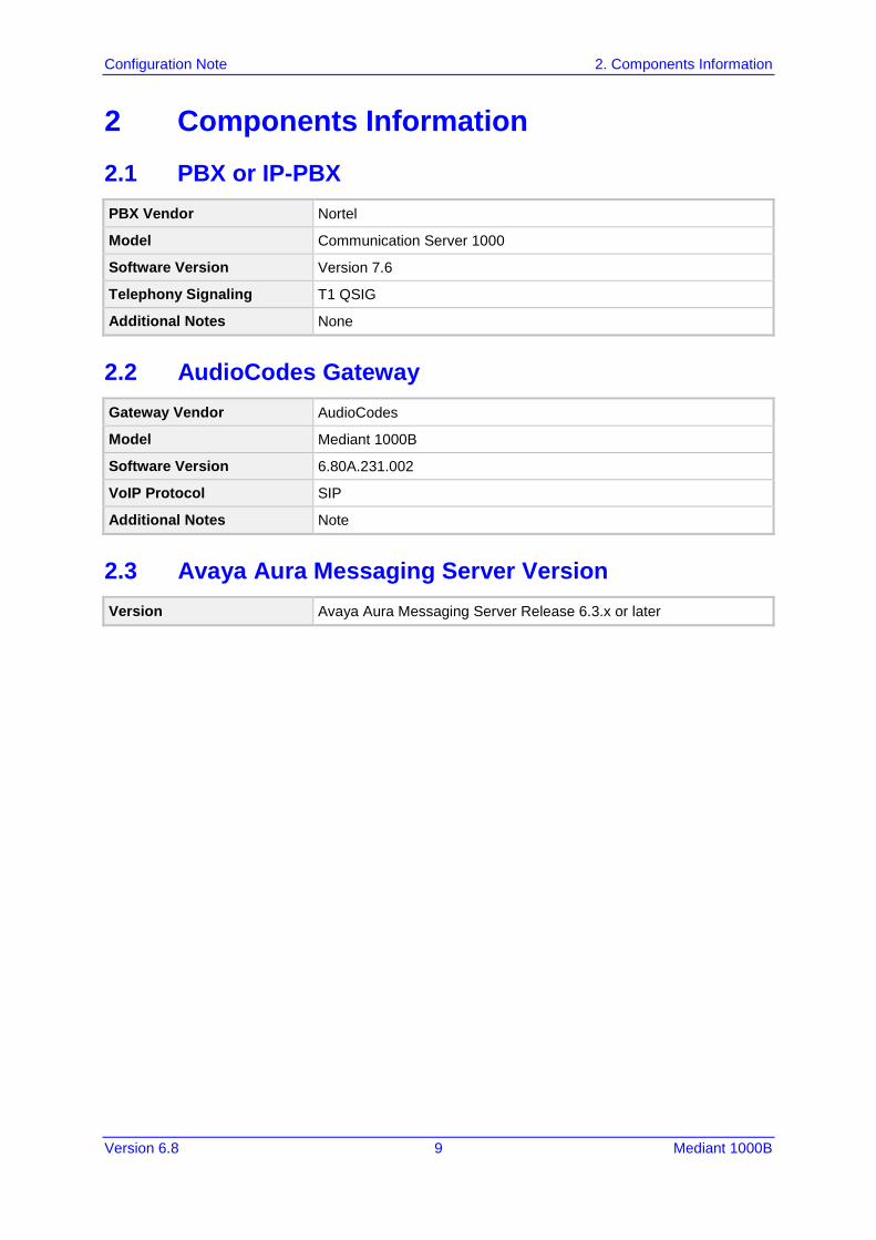
2 Components Information 2.1 PBX or IP-PBX PBX Vendor Nortel
Model Communication Server 1000
Software Version Version 7.6
Telephony Signaling T1 QSIG
Additional Notes None
2.2 AudioCodes Gateway Gateway Vendor AudioCodes
Model Mediant 1000B
Software Version 6.80A.231.002
VoIP Protocol SIP
Additional Notes Note
2.3 Avaya Aura Messaging Server Version Version Avaya Aura Messaging Server Release 6.3.x or later

Configuration Note 10 Document #: LTRT-12470
Avaya Aura Messaging & Nortel CS1000
This page is intentionally left blank.
Configuration Note 3. Prerequisites
Version 6.8 11 Mediant 1000B
3 Prerequisites 3.1 Gateway Prerequisites
None
3.2 PBX Prerequisites Refer to Section 4.1.
3.3 Cabling Requirements Refer to Section 4.1.

Configuration Note 12 Document #: LTRT-12470
Avaya Aura Messaging & Nortel CS1000
This page is intentionally left blank.
Configuration Note 4. PBX Setup Notes
Version 6.8 13 Mediant 1000B
4 PBX Setup Notes 4.1 PBX Configuration
Configure the PBX as specified in Section 5 of the Avaya Aura Messaging PBX Configuration Note (cn88024 – Nortel M1 T1 QSIG.pdf) at https://downloads.avaya.com/elmodocs2/Octel/mm_r2_0/cn88024.pdf.

Configuration Note 14 Document #: LTRT-12470
Avaya Aura Messaging & Nortel CS1000
This page is intentionally left blank.
Configuration Note 5. Gateway Configuration
Version 6.8 15 Mediant 1000B
5 Gateway Configuration The procedures below describe the configuration of AudioCodes’ gateway required for integration with both the PBX and the Avaya Aura Messaging System. You can configure the gateway using one of the following methods: Uploading an ini configuration file (*.ini file) – see Section 5.1 Configuring the gateway via the Web interface – see Section 5.2
5.1 Configuring the ini File For initial setup and configuration, you can upload an ini file (*.ini) to the AudioCodes gateway that includes the template ini file settings shown in Appendix A.
To upload an ini file:
1. Create a new text file (e.g., using Microsoft Notepad) with the file extension *.ini. 2. Copy the ini file settings from Appendix A and paste them into the text file. 3. Upload the file to the gateway. Typically, for interoperability with the deployed PBX interfaces and Avaya Aura Messaging, it is sufficient that you use this ini file template. However, due to specificity of site deployment, you may need to modify or define certain parameters (such as IP addresses and Trunk settings) after uploading the ini file.
5.2 Configuring AudioCodes Gateway The procedures below provide step-by-step instructions for configuring the AudioCodes gateway, using the Web interface. Ensure that you configure the gateway according to the configuration settings displayed in the screenshots provided below. The instructions describe how to setup Avaya Aura Messaging with the gateway implementing SIP over TLS with and without SRTP. Note the following Web interface guidelines: When making configuration changes for each procedure, ensure that you click the
Submit button to save your changes; unless otherwise instructed. Some of the changes may require a gateway reset for these changes to take effect.
Therefore, (and to save time), reset the gateway only after you complete all of the gateway configurations.
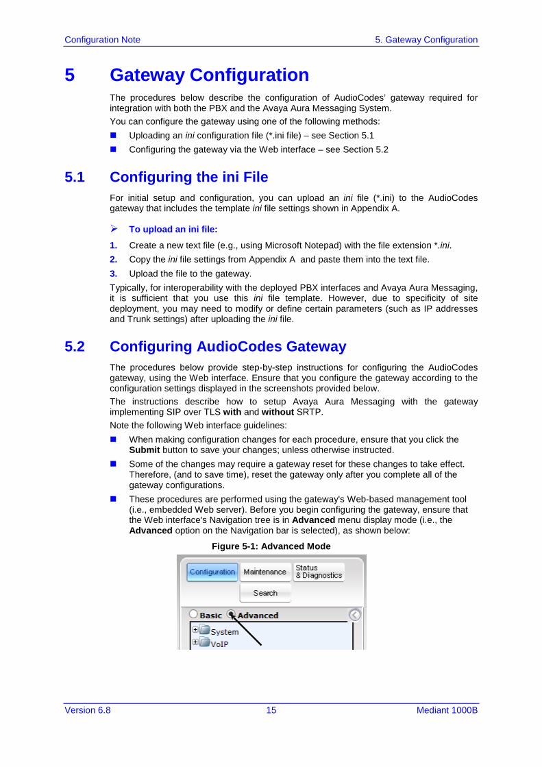
These procedures are performed using the gateway's Web-based management tool (i.e., embedded Web server). Before you begin configuring the gateway, ensure that the Web interface's Navigation tree is in Advanced menu display mode (i.e., the Advanced option on the Navigation bar is selected), as shown below:
Figure 5-1: Advanced Mode
Configuration Note 16 Document #: LTRT-12470
Avaya Aura Messaging & Nortel CS1000
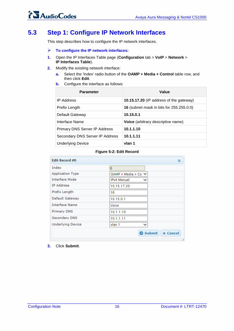
5.3 Step 1: Configure IP Network Interfaces This step describes how to configure the IP network interfaces.
To configure the IP network interfaces:
1. Open the IP Interfaces Table page (Configuration tab > VoIP > Network > IP Interfaces Table).
2. Modify the existing network interface: a. Select the 'Index' radio button of the OAMP + Media + Control table row, and
then click Edit. b. Configure the interface as follows:
Parameter Value
IP Address 10.15.17.20 (IP address of the gateway)
Prefix Length 16 (subnet mask in bits for 255.255.0.0)
Default Gateway 10.15.0.1
Interface Name Voice (arbitrary descriptive name)
Primary DNS Server IP Address 10.1.1.10
Secondary DNS Server IP Address 10.1.1.11
Underlying Device vlan 1
Figure 5-2: Edit Record
3. Click Submit.
Configuration Note 5. Gateway Configuration
Version 6.8 17 Mediant 1000B
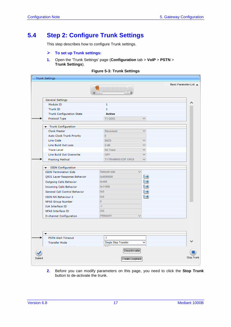
5.4 Step 2: Configure Trunk Settings This step describes how to configure Trunk settings.
To set up Trunk settings:
1. Open the 'Trunk Settings' page (Configuration tab > VoIP > PSTN > Trunk Settings).
Figure 5-3: Trunk Settings
2. Before you can modify parameters on this page, you need to click the Stop Trunk
button to de-activate the trunk.
Configuration Note 18 Document #: LTRT-12470
Avaya Aura Messaging & Nortel CS1000
3. Configure the relevant values to your setup for the following: • Protocol Type • Framing Method • Transfer Mode
4. After you configure the parameters, click the Apply Trunk Settings button, and then wait for the trunk settings to be applied. Once the trunk settings are applied, the trunk status icons at the top of the page change to green for all trunks that are connected to the PBX.
5. If there is more than one trunk connection between the PBX and gateway, repeat this step for each of the trunks, or click the Apply to All Trunks button.

Configuration Note 5. Gateway Configuration
Version 6.8 19 Mediant 1000B
5.5 Step 3: Configure TDM BUS Settings This step describes how to configure TDM Bus settings.
To configure TDM Bus settings:
1. Open the 'TDM Bus Settings' page (Configuration tab > VoIP > TDM > TDM Bus Settings).
Figure 5-4: TDM Bus Settings
2. From the ‘PCM Law Select’ drop-down list, select ‘MuLaw’. 3. From the ‘TDM Bus Clock Source’ drop-down list, select ‘Network’. 4. Click Submit.
Configuration Note 20 Document #: LTRT-12470
Avaya Aura Messaging & Nortel CS1000
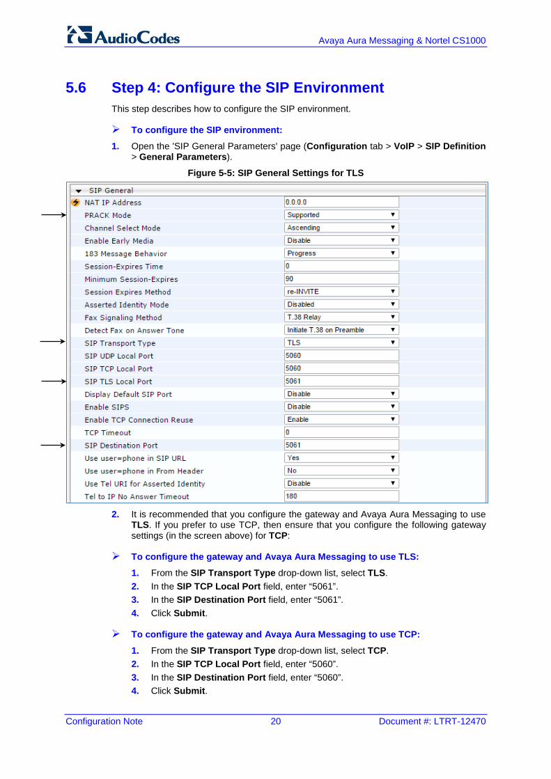
5.6 Step 4: Configure the SIP Environment This step describes how to configure the SIP environment.
To configure the SIP environment:
1. Open the 'SIP General Parameters' page (Configuration tab > VoIP > SIP Definition > General Parameters).
Figure 5-5: SIP General Settings for TLS
2. It is recommended that you configure the gateway and Avaya Aura Messaging to use
TLS. If you prefer to use TCP, then ensure that you configure the following gateway settings (in the screen above) for TCP:
To configure the gateway and Avaya Aura Messaging to use TLS:
1. From the SIP Transport Type drop-down list, select TLS. 2. In the SIP TCP Local Port field, enter “5061”. 3. In the SIP Destination Port field, enter “5061”. 4. Click Submit.
To configure the gateway and Avaya Aura Messaging to use TCP:
1. From the SIP Transport Type drop-down list, select TCP. 2. In the SIP TCP Local Port field, enter “5060”. 3. In the SIP Destination Port field, enter “5060”. 4. Click Submit.
Configuration Note 5. Gateway Configuration
Version 6.8 21 Mediant 1000B
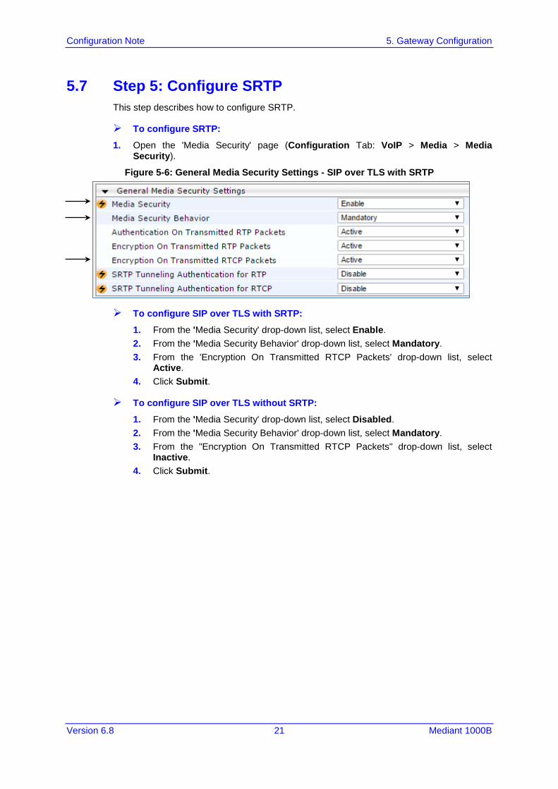
5.7 Step 5: Configure SRTP This step describes how to configure SRTP.
To configure SRTP:
1. Open the 'Media Security' page (Configuration Tab: VoIP > Media > Media Security).
Figure 5-6: General Media Security Settings - SIP over TLS with SRTP
To configure SIP over TLS with SRTP:
1. From the 'Media Security' drop-down list, select Enable. 2. From the 'Media Security Behavior' drop-down list, select Mandatory. 3. From the 'Encryption On Transmitted RTCP Packets' drop-down list, select
Active. 4. Click Submit.
To configure SIP over TLS without SRTP:
1. From the 'Media Security' drop-down list, select Disabled. 2. From the 'Media Security Behavior' drop-down list, select Mandatory. 3. From the "Encryption On Transmitted RTCP Packets" drop-down list, select
Inactive. 4. Click Submit.
Configuration Note 22 Document #: LTRT-12470
Avaya Aura Messaging & Nortel CS1000
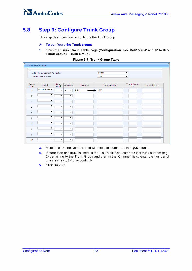
5.8 Step 6: Configure Trunk Group This step describes how to configure the Trunk group.
To configure the Trunk group:
1. Open the 'Trunk Group Table' page (Configuration Tab: VoIP > GW and IP to IP > Trunk Group > Trunk Group).
Figure 5-7: Trunk Group Table
3. Match the ‘Phone Number’ field with the pilot number of the QSIG trunk. 4. If more than one trunk is used, in the ‘To Trunk’ field, enter the last trunk number (e.g.,
2) pertaining to the Trunk Group and then in the ‘Channel’ field, enter the number of channels (e.g., 1-48) accordingly.
5. Click Submit.

Configuration Note 5. Gateway Configuration
Version 6.8 23 Mediant 1000B
5.9 Step 7: Configure SIP Environment and Gateway Name This step describes how to configure the SIP Environment and Gateway Name.
To configure the SIP Environment and Gateway Name:
Open the 'Proxy & Registration' page (Configuration tab > VoIP > SIP Definitions > Proxy & Registration). 1. In the 'Gateway Name' field, enter an FQDN name to the gateway (for example, SIP-
GW.com). Any gateway name that corresponds to your network environment is applicable, but it must meet requirements for FQDNs.
Figure 5-8: Proxy & Registration
2. Open the 'Proxy & Registration' page (Configuration tab > VoIP > VoIP Network >
Proxy Sets Table). 3. From the 'Proxy Set ID' drop-down list, select 1.
Figure 5-9: Proxy Set ID
4. In the ‘Proxy Address’ field, enter either the IP address or FQDN of the Avaya Aura
Messaging (AAM). If your Avaya Aura Messaging system includes multiple AAM’s, then enter multiple IP addresses or FQDNs for the MAS’s - one AAM per table row. It is recommended that you use FQDNs.
Configuration Note 24 Document #: LTRT-12470
Avaya Aura Messaging & Nortel CS1000
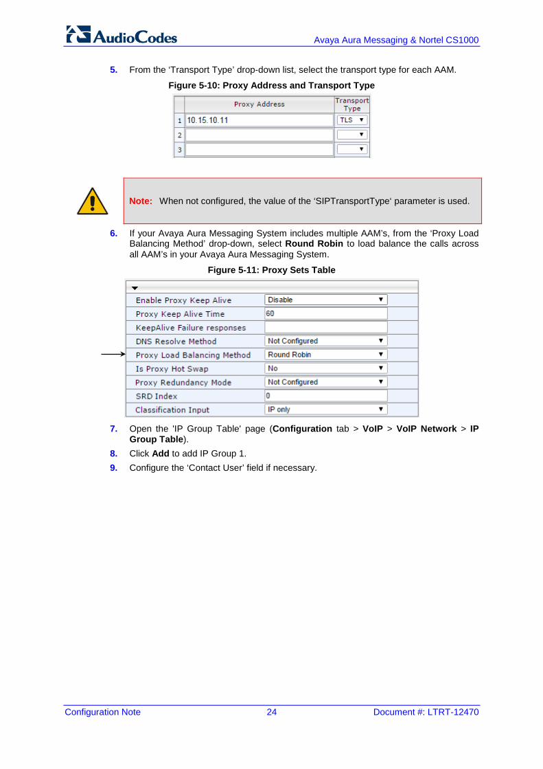
5. From the ‘Transport Type’ drop-down list, select the transport type for each AAM.
Figure 5-10: Proxy Address and Transport Type
Note: When not configured, the value of the ‘SIPTransportType‘ parameter is used.
6. If your Avaya Aura Messaging System includes multiple AAM’s, from the ‘Proxy Load Balancing Method’ drop-down, select Round Robin to load balance the calls across all AAM’s in your Avaya Aura Messaging System.
Figure 5-11: Proxy Sets Table
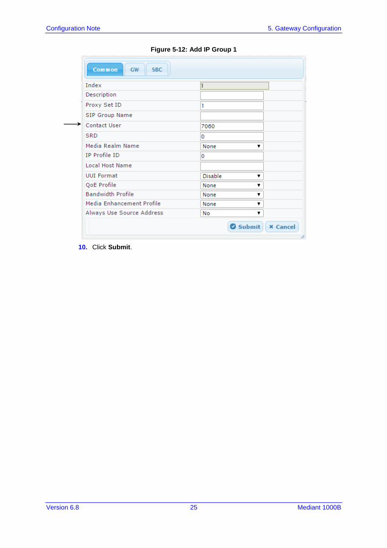
7. Open the 'IP Group Table' page (Configuration tab > VoIP > VoIP Network > IP
Group Table). 8. Click Add to add IP Group 1. 9. Configure the ‘Contact User’ field if necessary.
Configuration Note 5. Gateway Configuration
Version 6.8 25 Mediant 1000B
Figure 5-12: Add IP Group 1
10. Click Submit.
Configuration Note 26 Document #: LTRT-12470
Avaya Aura Messaging & Nortel CS1000
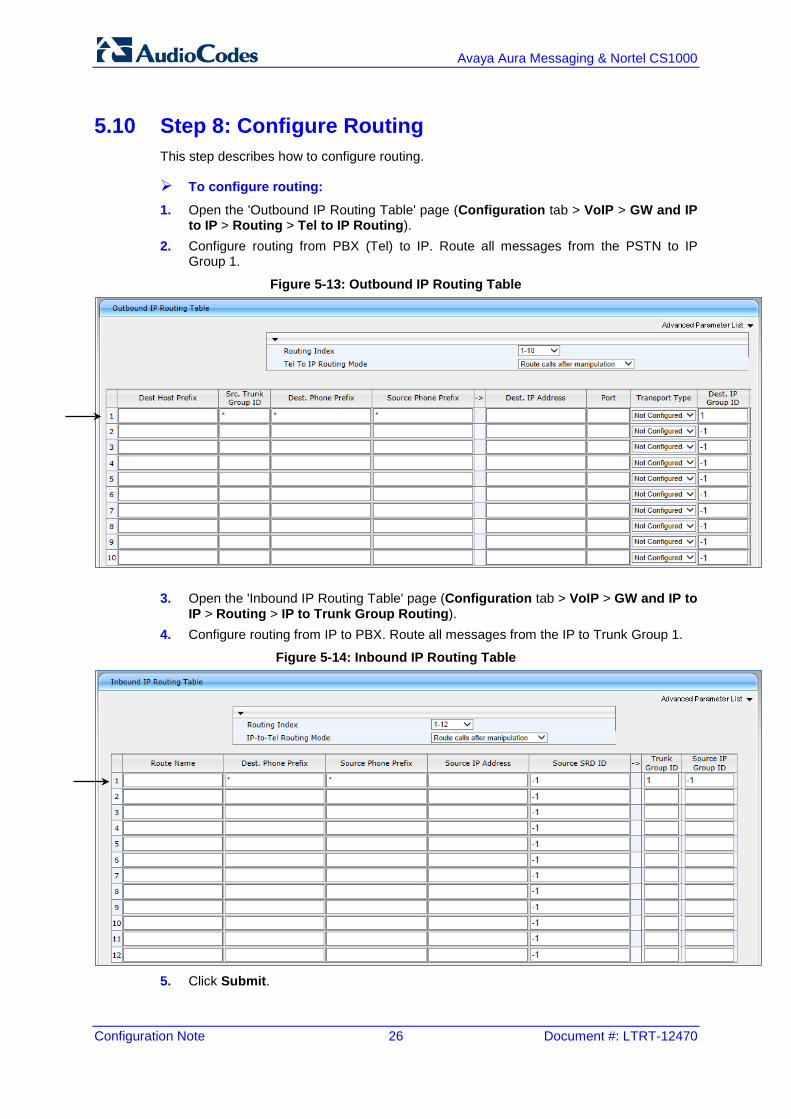
5.10 Step 8: Configure Routing This step describes how to configure routing.
To configure routing:
1. Open the 'Outbound IP Routing Table' page (Configuration tab > VoIP > GW and IP to IP > Routing > Tel to IP Routing).
2. Configure routing from PBX (Tel) to IP. Route all messages from the PSTN to IP Group 1.
Figure 5-13: Outbound IP Routing Table
3. Open the 'Inbound IP Routing Table' page (Configuration tab > VoIP > GW and IP to IP > Routing > IP to Trunk Group Routing).
4. Configure routing from IP to PBX. Route all messages from the IP to Trunk Group 1.
Figure 5-14: Inbound IP Routing Table
5. Click Submit.
Configuration Note 5. Gateway Configuration
Version 6.8 27 Mediant 1000B
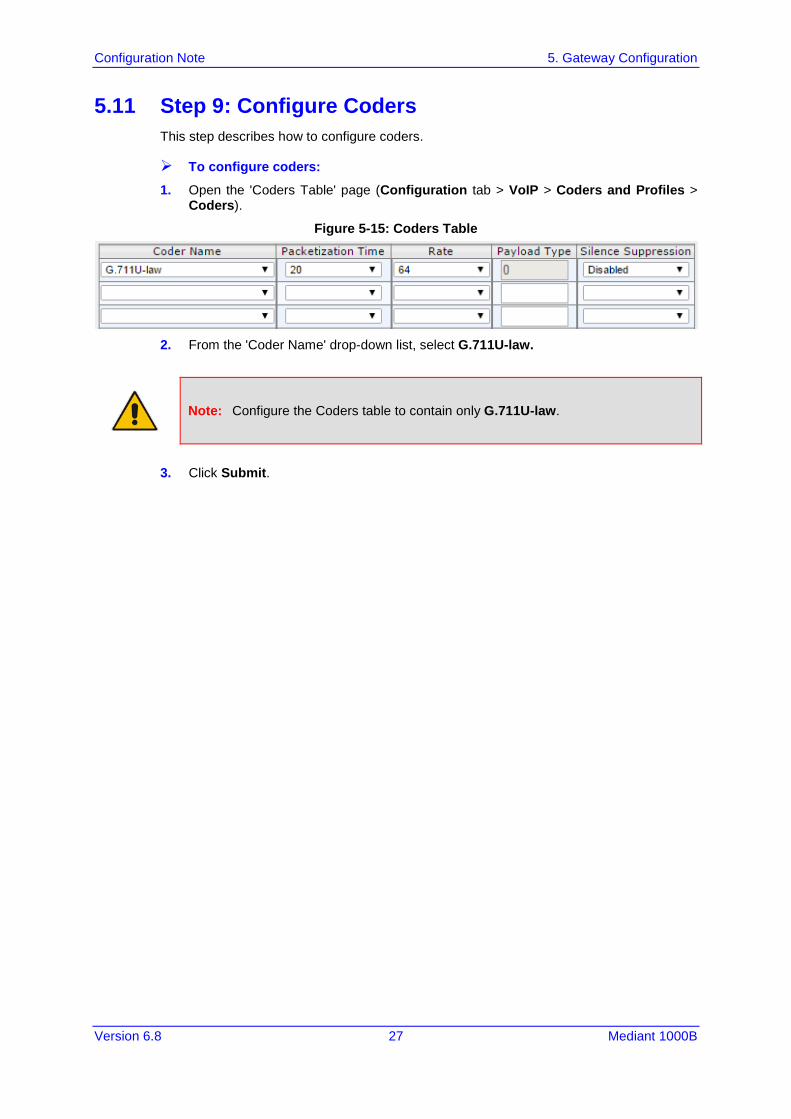
5.11 Step 9: Configure Coders This step describes how to configure coders.
To configure coders:
1. Open the 'Coders Table' page (Configuration tab > VoIP > Coders and Profiles > Coders).
Figure 5-15: Coders Table
2. From the 'Coder Name' drop-down list, select G.711U-law.
Note: Configure the Coders table to contain only G.711U-law.
3. Click Submit.
Configuration Note 28 Document #: LTRT-12470
Avaya Aura Messaging & Nortel CS1000
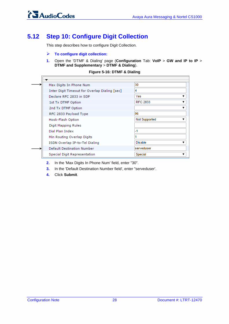
5.12 Step 10: Configure Digit Collection This step describes how to configure Digit Collection.
To configure digit collection:
1. Open the 'DTMF & Dialing' page (Configuration Tab: VoIP > GW and IP to IP > DTMF and Supplementary > DTMF & Dialing).
Figure 5-16: DTMF & Dialing
2. In the 'Max Digits In Phone Num' field, enter "30". 3. In the 'Default Destination Number field', enter "serveduser'. 4. Click Submit.
Configuration Note 5. Gateway Configuration
Version 6.8 29 Mediant 1000B
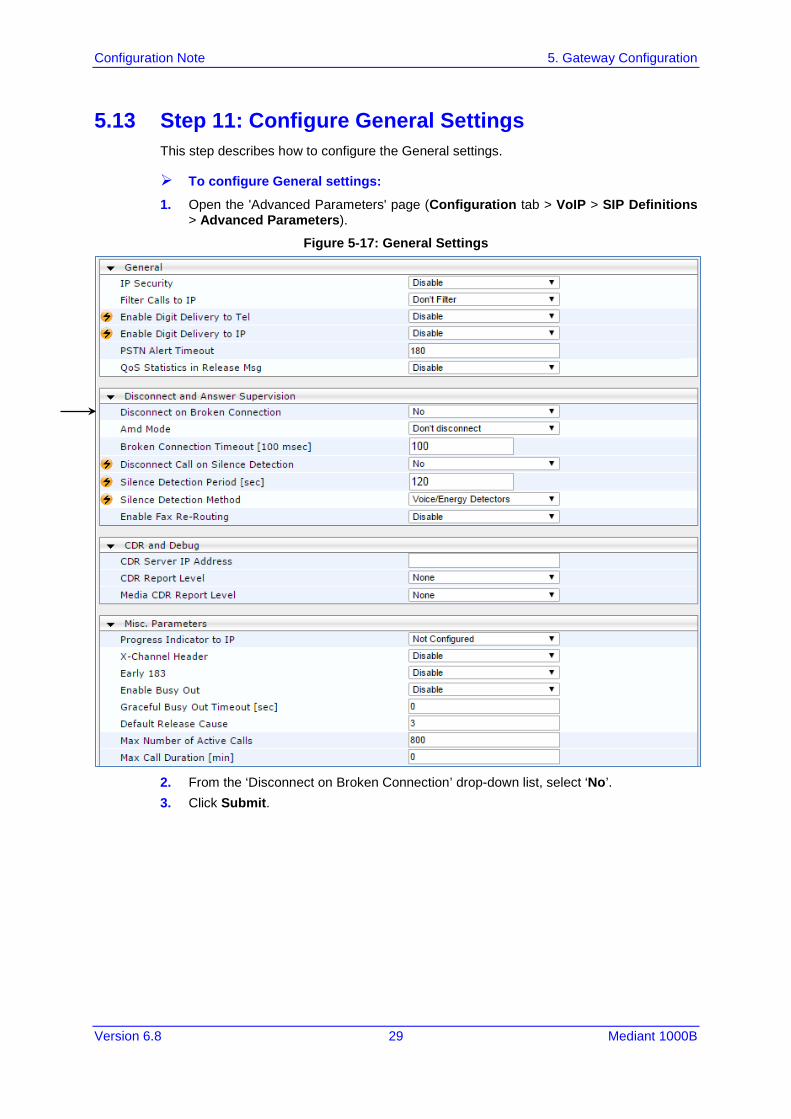
5.13 Step 11: Configure General Settings This step describes how to configure the General settings.
To configure General settings:
1. Open the 'Advanced Parameters' page (Configuration tab > VoIP > SIP Definitions > Advanced Parameters).
Figure 5-17: General Settings
2. From the ‘Disconnect on Broken Connection’ drop-down list, select ‘No’. 3. Click Submit.

Configuration Note 30 Document #: LTRT-12470
Avaya Aura Messaging & Nortel CS1000
5.14 Step 12: Configure Voice Mail Settings This step describes how to configure Voice Mail settings.
To configure Voice Mail Settings:
1. Open the 'Voice Mail Settings' page (Configuration Tab: VoIP > Services > Voice Mail Settings).
Figure 5-18: Voce Mail Settings
2. From the ‘Voice Mail Interface’ drop-down list, select ‘QSIG’. 3. Click Submit.
Configuration Note 5. Gateway Configuration
Version 6.8 31 Mediant 1000B
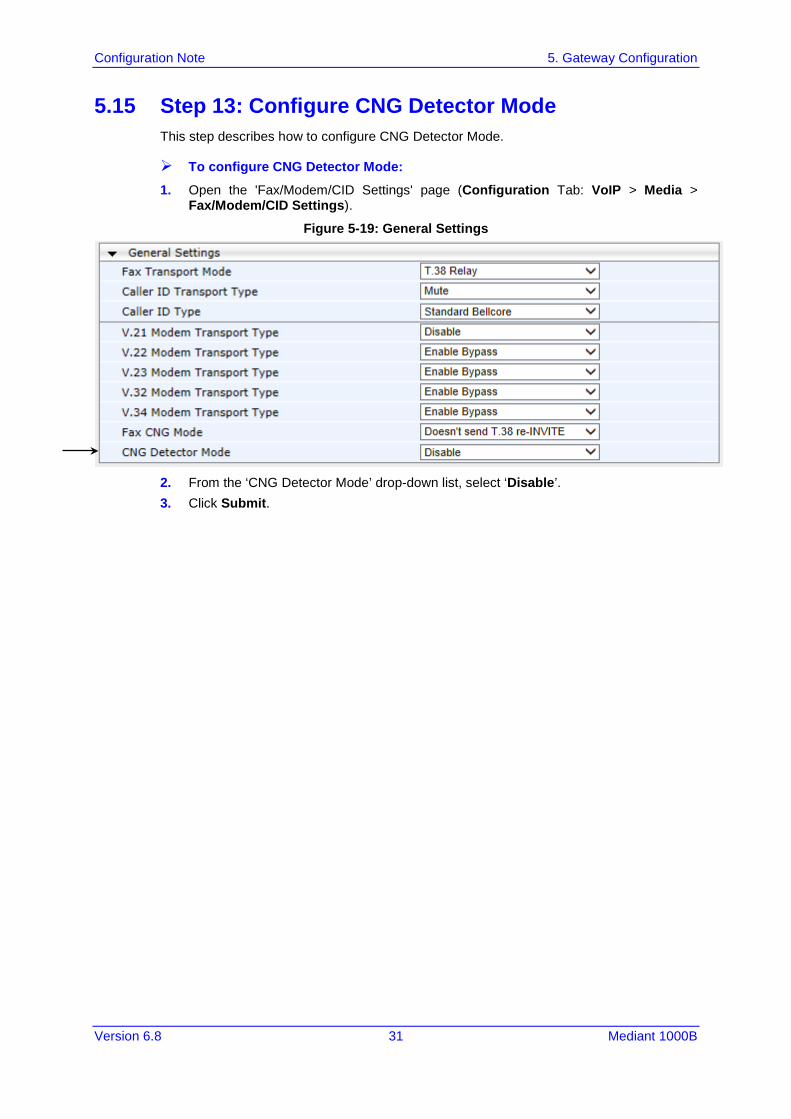
5.15 Step 13: Configure CNG Detector Mode This step describes how to configure CNG Detector Mode.
To configure CNG Detector Mode:
1. Open the 'Fax/Modem/CID Settings' page (Configuration Tab: VoIP > Media > Fax/Modem/CID Settings).
Figure 5-19: General Settings
2. From the ‘CNG Detector Mode’ drop-down list, select ‘Disable’. 3. Click Submit.
Configuration Note 32 Document #: LTRT-12470
Avaya Aura Messaging & Nortel CS1000
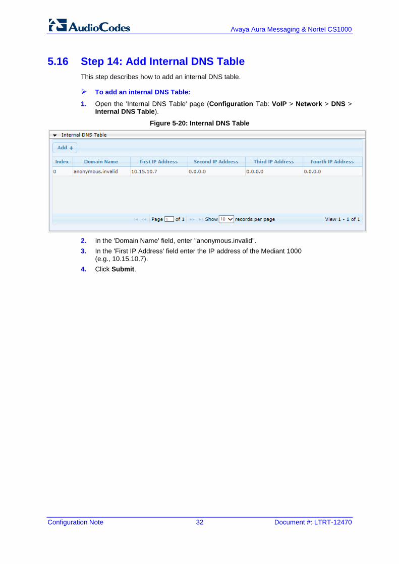
5.16 Step 14: Add Internal DNS Table This step describes how to add an internal DNS table.
To add an internal DNS Table:
1. Open the 'Internal DNS Table' page (Configuration Tab: VoIP > Network > DNS > Internal DNS Table).
Figure 5-20: Internal DNS Table
2. In the 'Domain Name' field, enter "anonymous.invalid". 3. In the 'First IP Address' field enter the IP address of the Mediant 1000
(e.g., 10.15.10.7). 4. Click Submit.

Configuration Note 5. Gateway Configuration
Version 6.8 33 Mediant 1000B
5.17 Step 15: Modify Parameters in the AdminPage This step describes how to modify parameters on the AdminPage.
To modify parameters on the AdminPage:
1. Open the 'AdminPage' page at the following URL (case-sensitive): http://<gateway’s IP address>/AdminPage
2. Click on the ini Parameters menu option. 3. In the ‘Parameter Name’ field, enter " ISDNIBehavior ". 2. In the ‘Enter Value’, enter “1073741824”. 4. Click Apply New Value. 5. In the Output Window, confirm that all the fields have been correctly updated. 6. Repeat Steps 3 to 5 for the following Parameter Names and appropriate Enter Values.
• ECNLPMode: “1” • EnableMWI: “1” • SubscriptionMode: “1”
Figure 5-21: AdminPage
Configuration Note 34 Document #: LTRT-12470
Avaya Aura Messaging & Nortel CS1000
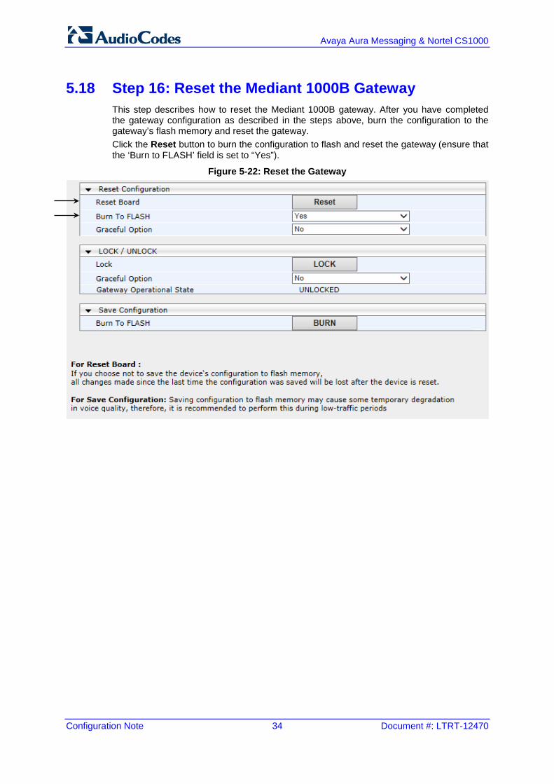
5.18 Step 16: Reset the Mediant 1000B Gateway This step describes how to reset the Mediant 1000B gateway. After you have completed the gateway configuration as described in the steps above, burn the configuration to the gateway’s flash memory and reset the gateway. Click the Reset button to burn the configuration to flash and reset the gateway (ensure that the ‘Burn to FLASH’ field is set to “Yes”).
Figure 5-22: Reset the Gateway
Configuration Note 6. Avaya Aura Messaging Server Configuration
Version 6.8 35 Mediant 1000B
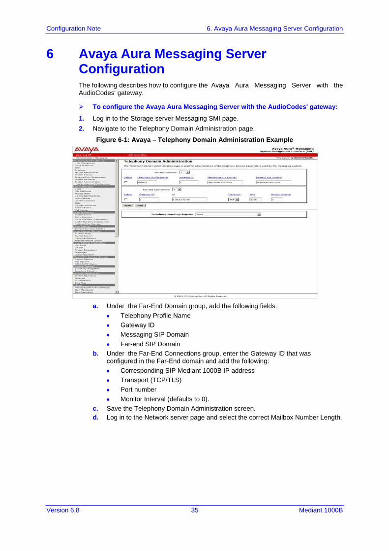
6 Avaya Aura Messaging Server Configuration The following describes how to configure the Avaya Aura Messaging Server with the AudioCodes' gateway.
To configure the Avaya Aura Messaging Server with the AudioCodes' gateway:
1. Log in to the Storage server Messaging SMI page. 2. Navigate to the Telephony Domain Administration page.
Figure 6-1: Avaya – Telephony Domain Administration Example
a. Under the Far-End Domain group, add the following fields:
♦ Telephony Profile Name ♦ Gateway ID ♦ Messaging SIP Domain ♦ Far-end SIP Domain
b. Under the Far-End Connections group, enter the Gateway ID that was configured in the Far-End domain and add the following: ♦ Corresponding SIP Mediant 1000B IP address ♦ Transport (TCP/TLS) ♦ Port number ♦ Monitor Interval (defaults to 0).
c. Save the Telephony Domain Administration screen. d. Log in to the Network server page and select the correct Mailbox Number Length.
Configuration Note 36 Document #: LTRT-12470
Avaya Aura Messaging & Nortel CS1000
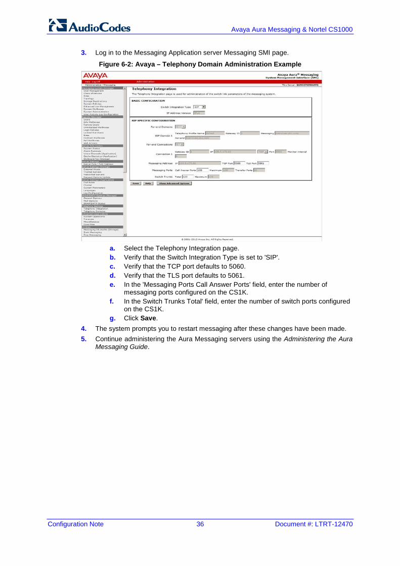
3. Log in to the Messaging Application server Messaging SMI page.
Figure 6-2: Avaya – Telephony Domain Administration Example
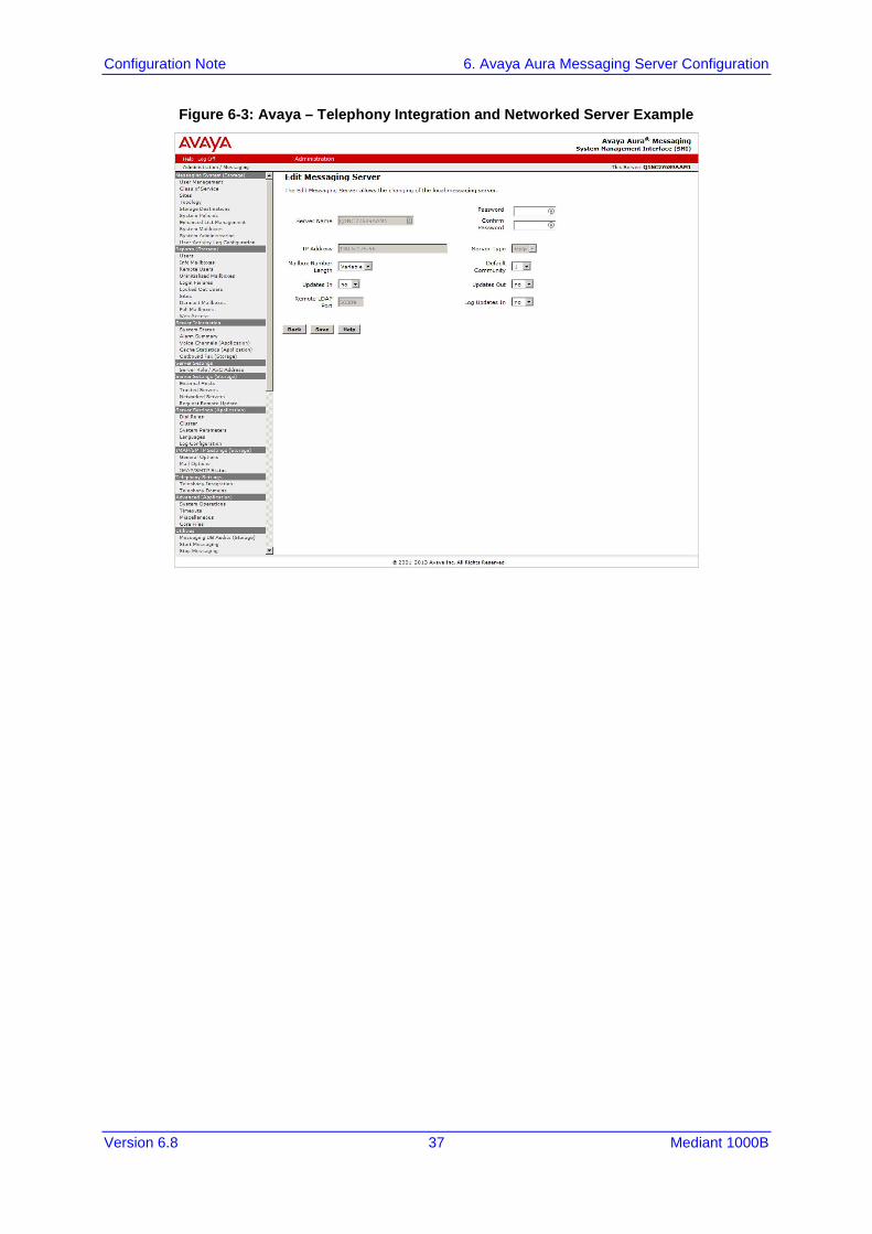
a. Select the Telephony Integration page. b. Verify that the Switch Integration Type is set to 'SIP'. c. Verify that the TCP port defaults to 5060. d. Verify that the TLS port defaults to 5061. e. In the 'Messaging Ports Call Answer Ports' field, enter the number of
messaging ports configured on the CS1K. f. In the Switch Trunks Total' field, enter the number of switch ports configured
on the CS1K. g. Click Save.
4. The system prompts you to restart messaging after these changes have been made. 5. Continue administering the Aura Messaging servers using the Administering the Aura
Messaging Guide.
Configuration Note 6. Avaya Aura Messaging Server Configuration
Version 6.8 37 Mediant 1000B
Figure 6-3: Avaya – Telephony Integration and Networked Server Example
Configuration Note 38 Document #: LTRT-12470
Avaya Aura Messaging & Nortel CS1000
This page is intentionally left blank.
Configuration Note 7. Troubleshooting
Version 6.8 39 Mediant 1000B
7 Troubleshooting The tools used for debugging include network sniffer applications (such as Wireshark) and AudioCodes' Syslog server application.
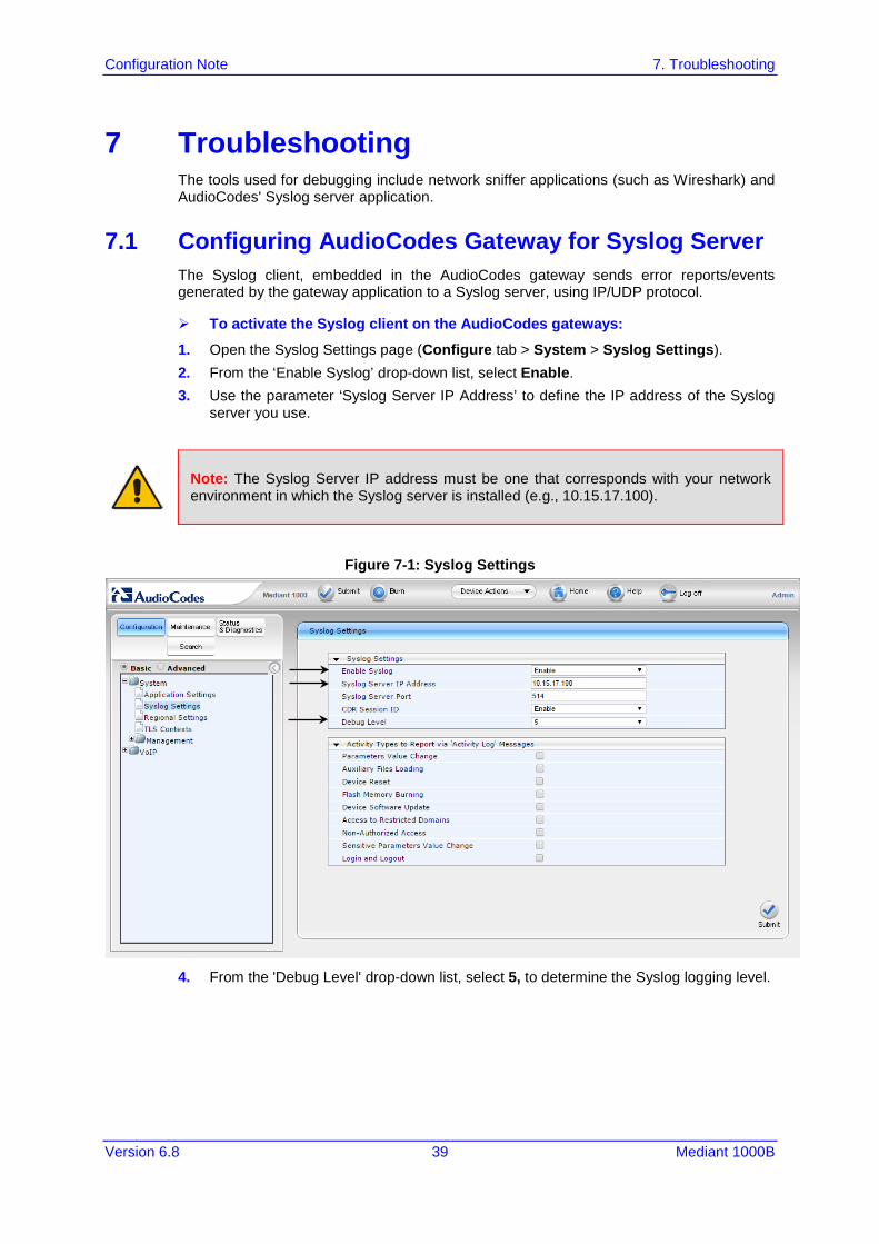
7.1 Configuring AudioCodes Gateway for Syslog Server The Syslog client, embedded in the AudioCodes gateway sends error reports/events generated by the gateway application to a Syslog server, using IP/UDP protocol.
To activate the Syslog client on the AudioCodes gateways:
1. Open the Syslog Settings page (Configure tab > System > Syslog Settings). 2. From the ‘Enable Syslog’ drop-down list, select Enable. 3. Use the parameter ‘Syslog Server IP Address’ to define the IP address of the Syslog
server you use.
Note: The Syslog Server IP address must be one that corresponds with your network environment in which the Syslog server is installed (e.g., 10.15.17.100).
Figure 7-1: Syslog Settings
4. From the 'Debug Level' drop-down list, select 5, to determine the Syslog logging level.
Configuration Note 40 Document #: LTRT-12470
Avaya Aura Messaging & Nortel CS1000
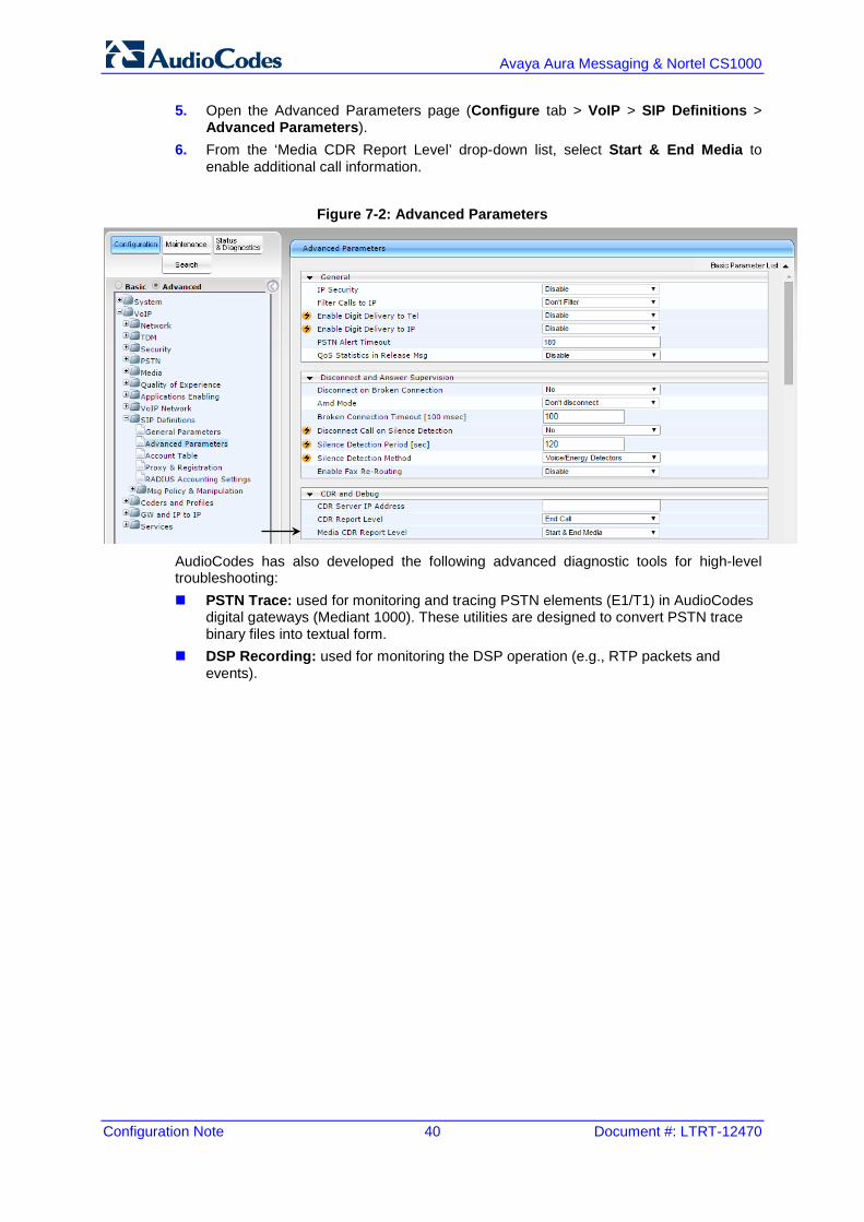
5. Open the Advanced Parameters page (Configure tab > VoIP > SIP Definitions > Advanced Parameters).
6. From the ‘Media CDR Report Level’ drop-down list, select Start & End Media to enable additional call information.
Figure 7-2: Advanced Parameters
AudioCodes has also developed the following advanced diagnostic tools for high-level troubleshooting: PSTN Trace: used for monitoring and tracing PSTN elements (E1/T1) in AudioCodes
digital gateways (Mediant 1000). These utilities are designed to convert PSTN trace binary files into textual form.
DSP Recording: used for monitoring the DSP operation (e.g., RTP packets and events).
Version 6.8 41 Mediant 1000B
Configuration Note A. AudioCodes ini File
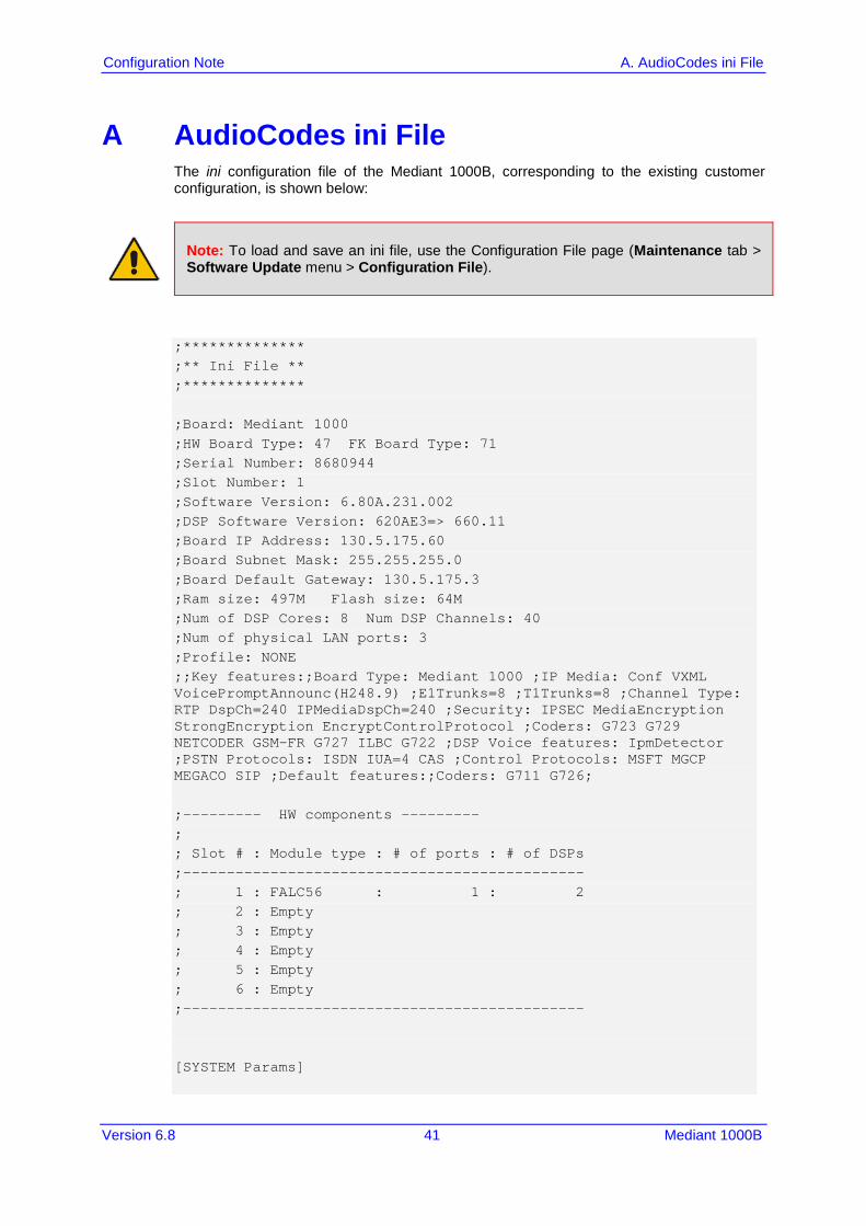
A AudioCodes ini File The ini configuration file of the Mediant 1000B, corresponding to the existing customer configuration, is shown below:
Note: To load and save an ini file, use the Configuration File page (Maintenance tab > Software Update menu > Configuration File).
;************** ;** Ini File ** ;************** ;Board: Mediant 1000 ;HW Board Type: 47 FK Board Type: 71 ;Serial Number: 8680944 ;Slot Number: 1 ;Software Version: 6.80A.231.002 ;DSP Software Version: 620AE3=> 660.11 ;Board IP Address: 130.5.175.60 ;Board Subnet Mask: 255.255.255.0 ;Board Default Gateway: 130.5.175.3 ;Ram size: 497M Flash size: 64M ;Num of DSP Cores: 8 Num DSP Channels: 40 ;Num of physical LAN ports: 3 ;Profile: NONE ;;Key features:;Board Type: Mediant 1000 ;IP Media: Conf VXML VoicePromptAnnounc(H248.9) ;E1Trunks=8 ;T1Trunks=8 ;Channel Type: RTP DspCh=240 IPMediaDspCh=240 ;Security: IPSEC MediaEncryption StrongEncryption EncryptControlProtocol ;Coders: G723 G729 NETCODER GSM-FR G727 ILBC G722 ;DSP Voice features: IpmDetector ;PSTN Protocols: ISDN IUA=4 CAS ;Control Protocols: MSFT MGCP MEGACO SIP ;Default features:;Coders: G711 G726; ;--------- HW components --------- ; ; Slot # : Module type : # of ports : # of DSPs ;---------------------------------------------- ; 1 : FALC56 : 1 : 2 ; 2 : Empty ; 3 : Empty ; 4 : Empty ; 5 : Empty ; 6 : Empty ;---------------------------------------------- [SYSTEM Params]
Configuration Note 42 Document #: LTRT-12470
Avaya Aura Messaging & Nortel CS1000
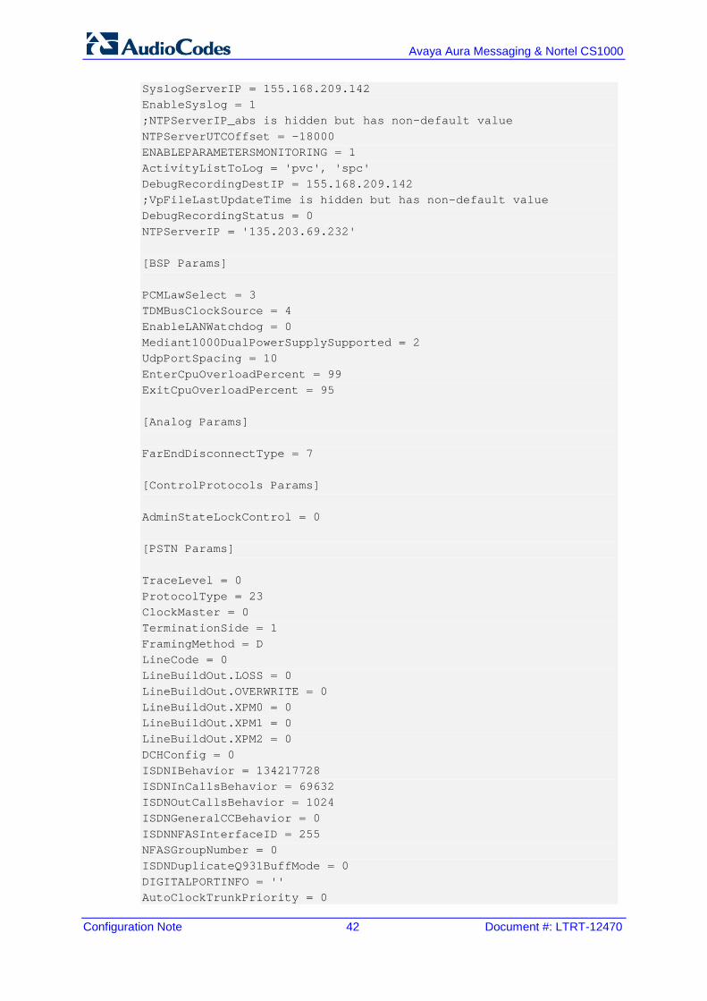
SyslogServerIP = 155.168.209.142 EnableSyslog = 1 ;NTPServerIP_abs is hidden but has non-default value NTPServerUTCOffset = -18000 ENABLEPARAMETERSMONITORING = 1 ActivityListToLog = 'pvc', 'spc' DebugRecordingDestIP = 155.168.209.142 ;VpFileLastUpdateTime is hidden but has non-default value DebugRecordingStatus = 0 NTPServerIP = '135.203.69.232' [BSP Params] PCMLawSelect = 3 TDMBusClockSource = 4 EnableLANWatchdog = 0 Mediant1000DualPowerSupplySupported = 2 UdpPortSpacing = 10 EnterCpuOverloadPercent = 99 ExitCpuOverloadPercent = 95 [Analog Params] FarEndDisconnectType = 7 [ControlProtocols Params] AdminStateLockControl = 0 [PSTN Params] TraceLevel = 0 ProtocolType = 23 ClockMaster = 0 TerminationSide = 1 FramingMethod = D LineCode = 0 LineBuildOut.LOSS = 0 LineBuildOut.OVERWRITE = 0 LineBuildOut.XPM0 = 0 LineBuildOut.XPM1 = 0 LineBuildOut.XPM2 = 0 DCHConfig = 0 ISDNIBehavior = 134217728 ISDNInCallsBehavior = 69632 ISDNOutCallsBehavior = 1024 ISDNGeneralCCBehavior = 0 ISDNNFASInterfaceID = 255 NFASGroupNumber = 0 ISDNDuplicateQ931BuffMode = 0 DIGITALPORTINFO = '' AutoClockTrunkPriority = 0
Version 6.8 43 Mediant 1000B
Configuration Note A. AudioCodes ini File
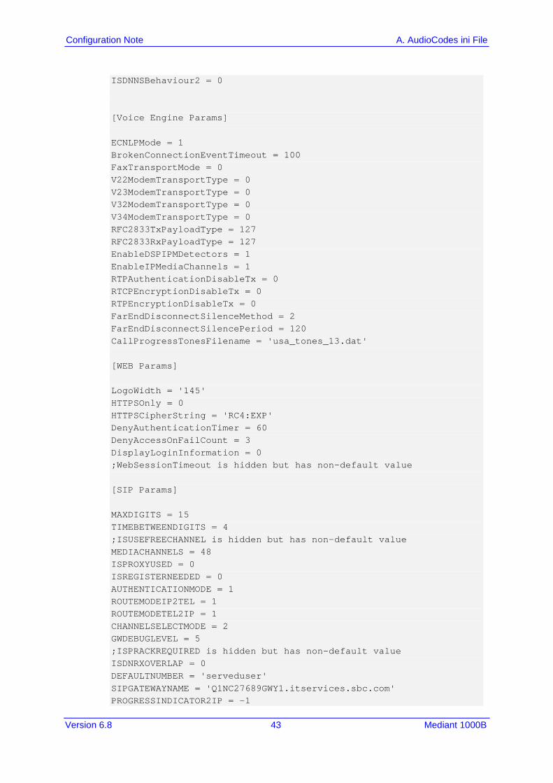
ISDNNSBehaviour2 = 0 [Voice Engine Params] ECNLPMode = 1 BrokenConnectionEventTimeout = 100 FaxTransportMode = 0 V22ModemTransportType = 0 V23ModemTransportType = 0 V32ModemTransportType = 0 V34ModemTransportType = 0 RFC2833TxPayloadType = 127 RFC2833RxPayloadType = 127 EnableDSPIPMDetectors = 1 EnableIPMediaChannels = 1 RTPAuthenticationDisableTx = 0 RTCPEncryptionDisableTx = 0 RTPEncryptionDisableTx = 0 FarEndDisconnectSilenceMethod = 2 FarEndDisconnectSilencePeriod = 120 CallProgressTonesFilename = 'usa_tones_13.dat' [WEB Params] LogoWidth = '145' HTTPSOnly = 0 HTTPSCipherString = 'RC4:EXP' DenyAuthenticationTimer = 60 DenyAccessOnFailCount = 3 DisplayLoginInformation = 0 ;WebSessionTimeout is hidden but has non-default value [SIP Params] MAXDIGITS = 15 TIMEBETWEENDIGITS = 4 ;ISUSEFREECHANNEL is hidden but has non-default value MEDIACHANNELS = 48 ISPROXYUSED = 0 ISREGISTERNEEDED = 0 AUTHENTICATIONMODE = 1 ROUTEMODEIP2TEL = 1 ROUTEMODETEL2IP = 1 CHANNELSELECTMODE = 2 GWDEBUGLEVEL = 5 ;ISPRACKREQUIRED is hidden but has non-default value ISDNRXOVERLAP = 0 DEFAULTNUMBER = 'serveduser' SIPGATEWAYNAME = 'Q1NC27689GWY1.itservices.sbc.com' PROGRESSINDICATOR2IP = -1
Configuration Note 44 Document #: LTRT-12470
Avaya Aura Messaging & Nortel CS1000
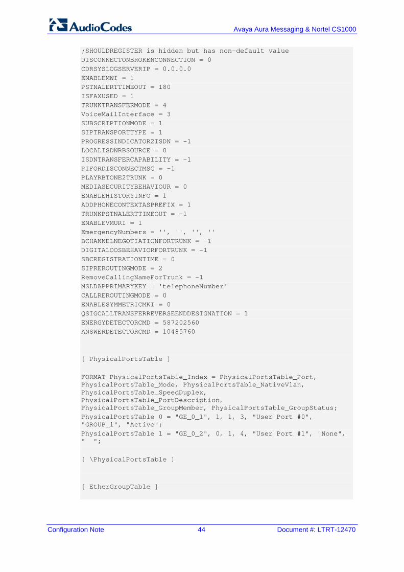
;SHOULDREGISTER is hidden but has non-default value DISCONNECTONBROKENCONNECTION = 0 CDRSYSLOGSERVERIP = 0.0.0.0 ENABLEMWI = 1 PSTNALERTTIMEOUT = 180 ISFAXUSED = 1 TRUNKTRANSFERMODE = 4 VoiceMailInterface = 3 SUBSCRIPTIONMODE = 1 SIPTRANSPORTTYPE = 1 PROGRESSINDICATOR2ISDN = -1 LOCALISDNRBSOURCE = 0 ISDNTRANSFERCAPABILITY = -1 PIFORDISCONNECTMSG = -1 PLAYRBTONE2TRUNK = 0 MEDIASECURITYBEHAVIOUR = 0 ENABLEHISTORYINFO = 1 ADDPHONECONTEXTASPREFIX = 1 TRUNKPSTNALERTTIMEOUT = -1 ENABLEVMURI = 1 EmergencyNumbers = '', '', '', '' BCHANNELNEGOTIATIONFORTRUNK = -1 DIGITALOOSBEHAVIORFORTRUNK = -1 SBCREGISTRATIONTIME = 0 SIPREROUTINGMODE = 2 RemoveCallingNameForTrunk = -1 MSLDAPPRIMARYKEY = 'telephoneNumber' CALLREROUTINGMODE = 0 ENABLESYMMETRICMKI = 0 QSIGCALLTRANSFERREVERSEENDDESIGNATION = 1 ENERGYDETECTORCMD = 587202560 ANSWERDETECTORCMD = 10485760 [ PhysicalPortsTable ] FORMAT PhysicalPortsTable_Index = PhysicalPortsTable_Port, PhysicalPortsTable_Mode, PhysicalPortsTable_NativeVlan, PhysicalPortsTable_SpeedDuplex, PhysicalPortsTable_PortDescription, PhysicalPortsTable_GroupMember, PhysicalPortsTable_GroupStatus; PhysicalPortsTable 0 = "GE_0_1", 1, 1, 3, "User Port #0", "GROUP_1", "Active"; PhysicalPortsTable 1 = "GE_0_2", 0, 1, 4, "User Port #1", "None", " "; [ \PhysicalPortsTable ] [ EtherGroupTable ]
Version 6.8 45 Mediant 1000B
Configuration Note A. AudioCodes ini File
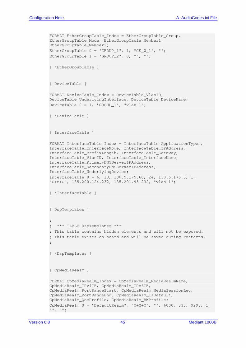
FORMAT EtherGroupTable_Index = EtherGroupTable_Group, EtherGroupTable_Mode, EtherGroupTable_Member1, EtherGroupTable_Member2; EtherGroupTable 0 = "GROUP_1", 1, "GE_0_1", ""; EtherGroupTable 1 = "GROUP_2", 0, "", ""; [ \EtherGroupTable ] [ DeviceTable ] FORMAT DeviceTable_Index = DeviceTable_VlanID, DeviceTable_UnderlyingInterface, DeviceTable_DeviceName; DeviceTable 0 = 1, "GROUP_1", "vlan 1"; [ \DeviceTable ] [ InterfaceTable ] FORMAT InterfaceTable_Index = InterfaceTable_ApplicationTypes, InterfaceTable_InterfaceMode, InterfaceTable_IPAddress, InterfaceTable_PrefixLength, InterfaceTable_Gateway, InterfaceTable_VlanID, InterfaceTable_InterfaceName, InterfaceTable_PrimaryDNSServerIPAddress, InterfaceTable_SecondaryDNSServerIPAddress, InterfaceTable_UnderlyingDevice; InterfaceTable 0 = 6, 10, 130.5.175.60, 24, 130.5.175.3, 1, "O+M+C", 135.200.124.232, 135.201.95.232, "vlan 1"; [ \InterfaceTable ] [ DspTemplates ] ; ; *** TABLE DspTemplates *** ; This table contains hidden elements and will not be exposed. ; This table exists on board and will be saved during restarts. ; [ \DspTemplates ] [ CpMediaRealm ] FORMAT CpMediaRealm_Index = CpMediaRealm_MediaRealmName, CpMediaRealm_IPv4IF, CpMediaRealm_IPv6IF, CpMediaRealm_PortRangeStart, CpMediaRealm_MediaSessionLeg, CpMediaRealm_PortRangeEnd, CpMediaRealm_IsDefault, CpMediaRealm_QoeProfile, CpMediaRealm_BWProfile; CpMediaRealm 0 = "DefaultRealm", "O+M+C", "", 6000, 330, 9290, 1, "", "";
Configuration Note 46 Document #: LTRT-12470
Avaya Aura Messaging & Nortel CS1000
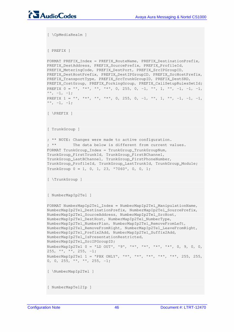
[ \CpMediaRealm ] [ PREFIX ] FORMAT PREFIX_Index = PREFIX_RouteName, PREFIX_DestinationPrefix, PREFIX_DestAddress, PREFIX_SourcePrefix, PREFIX_ProfileId, PREFIX_MeteringCode, PREFIX_DestPort, PREFIX_SrcIPGroupID, PREFIX_DestHostPrefix, PREFIX_DestIPGroupID, PREFIX_SrcHostPrefix, PREFIX_TransportType, PREFIX_SrcTrunkGroupID, PREFIX_DestSRD, PREFIX_CostGroup, PREFIX_ForkingGroup, PREFIX_CallSetupRulesSetId; PREFIX 0 = "", "*", "", "*", 0, 255, 0, -1, "", 1, "", -1, -1, -1, "", -1, -1; PREFIX 1 = "", "*", "", "*", 0, 255, 0, -1, "", 1, "", -1, -1, -1, "", -1, -1; [ \PREFIX ] [ TrunkGroup ] ; ** NOTE: Changes were made to active configuration. ; ** The data below is different from current values. FORMAT TrunkGroup_Index = TrunkGroup_TrunkGroupNum, TrunkGroup_FirstTrunkId, TrunkGroup_FirstBChannel, TrunkGroup_LastBChannel, TrunkGroup_FirstPhoneNumber, TrunkGroup_ProfileId, TrunkGroup_LastTrunkId, TrunkGroup_Module; TrunkGroup 0 = 1, 0, 1, 23, "7060", 0, 0, 1; [ \TrunkGroup ] [ NumberMapIp2Tel ] FORMAT NumberMapIp2Tel_Index = NumberMapIp2Tel_ManipulationName, NumberMapIp2Tel_DestinationPrefix, NumberMapIp2Tel_SourcePrefix, NumberMapIp2Tel_SourceAddress, NumberMapIp2Tel_SrcHost, NumberMapIp2Tel_DestHost, NumberMapIp2Tel_NumberType, NumberMapIp2Tel_NumberPlan, NumberMapIp2Tel_RemoveFromLeft, NumberMapIp2Tel_RemoveFromRight, NumberMapIp2Tel_LeaveFromRight, NumberMapIp2Tel_Prefix2Add, NumberMapIp2Tel_Suffix2Add, NumberMapIp2Tel_IsPresentationRestricted, NumberMapIp2Tel_SrcIPGroupID; NumberMapIp2Tel 0 = "LD OUT", "9", "*", "*", "*", "*", 0, 9, 0, 0, 255, "", "", 255, -1; NumberMapIp2Tel 1 = "PBX ONLY", "*", "*", "*", "*", "*", 255, 255, 0, 0, 255, "", "", 255, -1; [ \NumberMapIp2Tel ] [ NumberMapTel2Ip ]
Version 6.8 47 Mediant 1000B
Configuration Note A. AudioCodes ini File
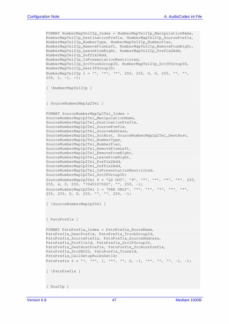
FORMAT NumberMapTel2Ip_Index = NumberMapTel2Ip_ManipulationName, NumberMapTel2Ip_DestinationPrefix, NumberMapTel2Ip_SourcePrefix, NumberMapTel2Ip_NumberType, NumberMapTel2Ip_NumberPlan, NumberMapTel2Ip_RemoveFromLeft, NumberMapTel2Ip_RemoveFromRight, NumberMapTel2Ip_LeaveFromRight, NumberMapTel2Ip_Prefix2Add, NumberMapTel2Ip_Suffix2Add, NumberMapTel2Ip_IsPresentationRestricted, NumberMapTel2Ip_SrcTrunkGroupID, NumberMapTel2Ip_SrcIPGroupID, NumberMapTel2Ip_DestIPGroupID; NumberMapTel2Ip 1 = "", "*", "*", 255, 255, 0, 0, 255, "", "", 255, 1, -1, -1; [ \NumberMapTel2Ip ] [ SourceNumberMapIp2Tel ] FORMAT SourceNumberMapIp2Tel_Index = SourceNumberMapIp2Tel_ManipulationName, SourceNumberMapIp2Tel_DestinationPrefix, SourceNumberMapIp2Tel_SourcePrefix, SourceNumberMapIp2Tel_SourceAddress, SourceNumberMapIp2Tel_SrcHost, SourceNumberMapIp2Tel_DestHost, SourceNumberMapIp2Tel_NumberType, SourceNumberMapIp2Tel_NumberPlan, SourceNumberMapIp2Tel_RemoveFromLeft, SourceNumberMapIp2Tel_RemoveFromRight, SourceNumberMapIp2Tel_LeaveFromRight, SourceNumberMapIp2Tel_Prefix2Add, SourceNumberMapIp2Tel_Suffix2Add, SourceNumberMapIp2Tel_IsPresentationRestricted, SourceNumberMapIp2Tel_SrcIPGroupID; SourceNumberMapIp2Tel 0 = "LD OUT", "9", "*", "*", "*", "*", 255, 255, 4, 0, 255, "7045107000", "", 255, -1; SourceNumberMapIp2Tel 1 = "PBX ONLY", "*", "*", "*", "*", "*", 255, 255, 0, 0, 255, "", "", 255, -1; [ \SourceNumberMapIp2Tel ] [ PstnPrefix ] FORMAT PstnPrefix_Index = PstnPrefix_RouteName, PstnPrefix_DestPrefix, PstnPrefix_TrunkGroupId, PstnPrefix_SourcePrefix, PstnPrefix_SourceAddress, PstnPrefix_ProfileId, PstnPrefix_SrcIPGroupID, PstnPrefix_DestHostPrefix, PstnPrefix_SrcHostPrefix, PstnPrefix_SrcSRDID, PstnPrefix_TrunkId, PstnPrefix_CallSetupRulesSetId; PstnPrefix 0 = "", "*", 1, "*", "", 0, -1, "*", "", "", -1, -1; [ \PstnPrefix ] [ Dns2Ip ]
Configuration Note 48 Document #: LTRT-12470
Avaya Aura Messaging & Nortel CS1000
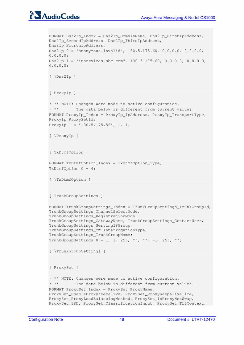
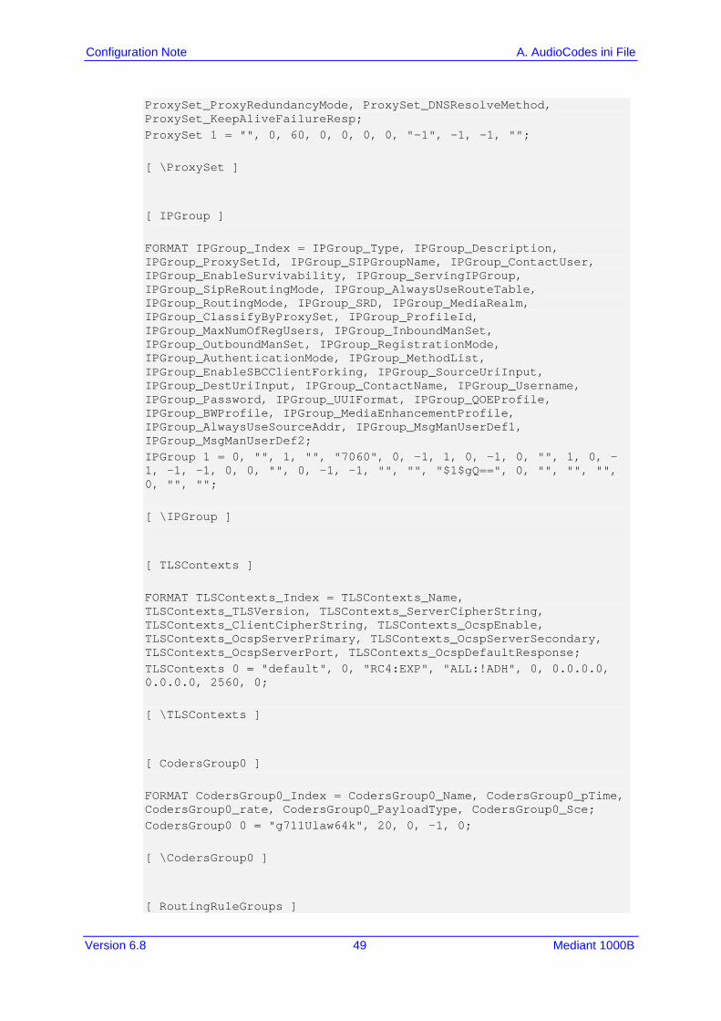
FORMAT Dns2Ip_Index = Dns2Ip_DomainName, Dns2Ip_FirstIpAddress, Dns2Ip_SecondIpAddress, Dns2Ip_ThirdIpAddress, Dns2Ip_FourthIpAddress; Dns2Ip 0 = "anonymous.invalid", 130.5.175.60, 0.0.0.0, 0.0.0.0, 0.0.0.0; Dns2Ip 1 = "itservices.sbc.com", 130.5.175.60, 0.0.0.0, 0.0.0.0, 0.0.0.0; [ \Dns2Ip ] [ ProxyIp ] ; ** NOTE: Changes were made to active configuration. ; ** The data below is different from current values. FORMAT ProxyIp_Index = ProxyIp_IpAddress, ProxyIp_TransportType, ProxyIp_ProxySetId; ProxyIp 1 = "130.5.175.56", 1, 1; [ \ProxyIp ] [ TxDtmfOption ] FORMAT TxDtmfOption_Index = TxDtmfOption_Type; TxDtmfOption 0 = 4; [ \TxDtmfOption ] [ TrunkGroupSettings ] FORMAT TrunkGroupSettings_Index = TrunkGroupSettings_TrunkGroupId, TrunkGroupSettings_ChannelSelectMode, TrunkGroupSettings_RegistrationMode, TrunkGroupSettings_GatewayName, TrunkGroupSettings_ContactUser, TrunkGroupSettings_ServingIPGroup, TrunkGroupSettings_MWIInterrogationType, TrunkGroupSettings_TrunkGroupName; TrunkGroupSettings 0 = 1, 1, 255, "", "", -1, 255, ""; [ \TrunkGroupSettings ] [ ProxySet ] ; ** NOTE: Changes were made to active configuration. ; ** The data below is different from current values. FORMAT ProxySet_Index = ProxySet_ProxyName, ProxySet_EnableProxyKeepAlive, ProxySet_ProxyKeepAliveTime, ProxySet_ProxyLoadBalancingMethod, ProxySet_IsProxyHotSwap, ProxySet_SRD, ProxySet_ClassificationInput, ProxySet_TLSContext,
Version 6.8 49 Mediant 1000B
Configuration Note A. AudioCodes ini File
ProxySet_ProxyRedundancyMode, ProxySet_DNSResolveMethod, ProxySet_KeepAliveFailureResp; ProxySet 1 = "", 0, 60, 0, 0, 0, 0, "-1", -1, -1, ""; [ \ProxySet ] [ IPGroup ] FORMAT IPGroup_Index = IPGroup_Type, IPGroup_Description, IPGroup_ProxySetId, IPGroup_SIPGroupName, IPGroup_ContactUser, IPGroup_EnableSurvivability, IPGroup_ServingIPGroup, IPGroup_SipReRoutingMode, IPGroup_AlwaysUseRouteTable, IPGroup_RoutingMode, IPGroup_SRD, IPGroup_MediaRealm, IPGroup_ClassifyByProxySet, IPGroup_ProfileId, IPGroup_MaxNumOfRegUsers, IPGroup_InboundManSet, IPGroup_OutboundManSet, IPGroup_RegistrationMode, IPGroup_AuthenticationMode, IPGroup_MethodList, IPGroup_EnableSBCClientForking, IPGroup_SourceUriInput, IPGroup_DestUriInput, IPGroup_ContactName, IPGroup_Username, IPGroup_Password, IPGroup_UUIFormat, IPGroup_QOEProfile, IPGroup_BWProfile, IPGroup_MediaEnhancementProfile, IPGroup_AlwaysUseSourceAddr, IPGroup_MsgManUserDef1, IPGroup_MsgManUserDef2; IPGroup 1 = 0, "", 1, "", "7060", 0, -1, 1, 0, -1, 0, "", 1, 0, -1, -1, -1, 0, 0, "", 0, -1, -1, "", "", "$1$gQ==", 0, "", "", "", 0, "", ""; [ \IPGroup ] [ TLSContexts ] FORMAT TLSContexts_Index = TLSContexts_Name, TLSContexts_TLSVersion, TLSContexts_ServerCipherString, TLSContexts_ClientCipherString, TLSContexts_OcspEnable, TLSContexts_OcspServerPrimary, TLSContexts_OcspServerSecondary, TLSContexts_OcspServerPort, TLSContexts_OcspDefaultResponse; TLSContexts 0 = "default", 0, "RC4:EXP", "ALL:!ADH", 0, 0.0.0.0, 0.0.0.0, 2560, 0; [ \TLSContexts ] [ CodersGroup0 ] FORMAT CodersGroup0_Index = CodersGroup0_Name, CodersGroup0_pTime, CodersGroup0_rate, CodersGroup0_PayloadType, CodersGroup0_Sce; CodersGroup0 0 = "g711Ulaw64k", 20, 0, -1, 0; [ \CodersGroup0 ] [ RoutingRuleGroups ]
Configuration Note 50 Document #: LTRT-12470
Avaya Aura Messaging & Nortel CS1000
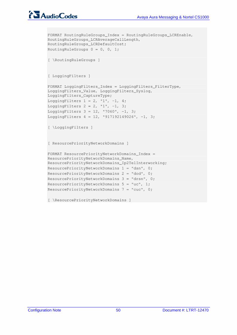
FORMAT RoutingRuleGroups_Index = RoutingRuleGroups_LCREnable, RoutingRuleGroups_LCRAverageCallLength, RoutingRuleGroups_LCRDefaultCost; RoutingRuleGroups 0 = 0, 0, 1; [ \RoutingRuleGroups ] [ LoggingFilters ] FORMAT LoggingFilters_Index = LoggingFilters_FilterType, LoggingFilters_Value, LoggingFilters_Syslog, LoggingFilters_CaptureType; LoggingFilters 1 = 2, "1", -1, 4; LoggingFilters 2 = 2, "1", -1, 3; LoggingFilters 3 = 12, "7060", -1, 3; LoggingFilters 4 = 12, "917192149026", -1, 3; [ \LoggingFilters ] [ ResourcePriorityNetworkDomains ] FORMAT ResourcePriorityNetworkDomains_Index = ResourcePriorityNetworkDomains_Name, ResourcePriorityNetworkDomains_Ip2TelInterworking; ResourcePriorityNetworkDomains 1 = "dsn", 0; ResourcePriorityNetworkDomains 2 = "dod", 0; ResourcePriorityNetworkDomains 3 = "drsn", 0; ResourcePriorityNetworkDomains 5 = "uc", 1; ResourcePriorityNetworkDomains 7 = "cuc", 0; [ \ResourcePriorityNetworkDomains ]
Version 6.8 51 Mediant 1000B
Configuration Note A. AudioCodes ini File
This page is intentionally left blank.
International Headquarters
Contact us: www.audiocodes.com/info Website: www.audiocodes.com Document #: LTRT-12470