HEAT RECOVERY SILENCERS FOR … RECOVERY SILENCERS FOR RECIPROCATING ENGINES MFT MAXIM SILENCERS,...
4
MFT HEAT RECOVERY SILENCERS FOR RECIPROCATING ENGINES MAXIM SILENCERS, INC. Rev. 12.01.08 Silencing + Quality Steam Generation or Liquid Heating APPLICATIONS: OPERATION CODE COMPLIANCE Flow Diagram Exhaust gas enters the heat recovery silencer through connection (1), makes a reversal at the lower end of the unit and passes up over the finned tubes through which the heat is transferred to the water. The gas exits through the exhaust outlet connections (2). The water enters through connection (3) and from there it enters the lower manifold and passes into the tubes. After absorbing the available heat the water (or steam and water mixture) exits through connection (4). There are many available combinations of exhaust gas and water flow but the same basic relationship will hold for all. Size Range: Exhaust connections from 2" through 30" in diameter Construction: The Maxim Finned Tube or MFT heat recovery silencers are basically water tube type. It is constructed to combine Maxim standards of silencing with a highly efficient heat exchanger design. This is possible through the use of extended surface tubes, which permit the design of a much more compact and light weight unit. The MFT has no moving parts and requires minimum routine maintenance. The unit must be installed vertically when used as a steam generator and may be installed vertically or horizontally when used as a liquid heater without affecting heat recovery or silencing characteristics. The heat recovery silencer shall provide sound attenuation equal to at least 28 dBA. Extended Heating Surface: The finned tube design is a means of greatly increasing the surface in contact with the hot exhaust gases by attaching longitudinal fins directly to the water tubes. By doing this the tube’s ability to transfer heat is increased by 700 to 800 percent. A further advantage is that at low exhaust flow conditions the efficiency of the fins increases tending to offset the reduced heat transfer rate to the tubes. This gives much higher recovery at part load operation than is possible with plain tube construction. All Maxim heat recovery equipment is designed and fabricated in compliance with Section VIII, Division I, ASME Code. • Hospitals • Schools • Office buildings • Shopping centers • Offshore platforms • Oil & Gas production facilities • Industrial plants • Marine Expansion: The tube bundle of the MFT is fixed at one end and free to slide on the other, thus minimizing thermal stresses. LEGEND WATER HOT WATER OR STEAM & WATER MIXTURE Exhaust outlet Exhaust inlet Water inlet Hot water or steam & water outlet 2 4 1 3
Transcript of HEAT RECOVERY SILENCERS FOR … RECOVERY SILENCERS FOR RECIPROCATING ENGINES MFT MAXIM SILENCERS,...
MFTHEAT RECOVERY SILENCERS FOR RECIPROCATING ENGINES
MAXIM SILENCERS, INC. Rev. 12.01.08
Silencing + Quality Steam Generation or Liquid Heating
AP
PLI
CA
TIO
NS:
OP
ER
ATI
ON
CO
DE
CO
MP
LIA
NC
E
Flow Diagram
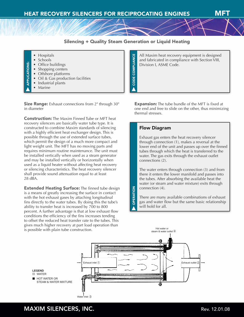
Exhaust gas enters the heat recovery silencer through connection (1), makes a reversal at the lower end of the unit and passes up over the finned tubes through which the heat is transferred to the water. The gas exits through the exhaust outlet connections (2).
The water enters through connection (3) and from there it enters the lower manifold and passes into the tubes. After absorbing the available heat the water (or steam and water mixture) exits through connection (4).
There are many available combinations of exhaust gas and water flow but the same basic relationship will hold for all.
Size Range: Exhaust connections from 2" through 30" in diameter
Construction: The Maxim Finned Tube or MFT heat recovery silencers are basically water tube type. It is constructed to combine Maxim standards of silencing with a highly efficient heat exchanger design. This is possible through the use of extended surface tubes, which permit the design of a much more compact and light weight unit. The MFT has no moving parts and requires minimum routine maintenance. The unit must be installed vertically when used as a steam generator and may be installed vertically or horizontally when used as a liquid heater without affecting heat recovery or silencing characteristics. The heat recovery silencer shall provide sound attenuation equal to at least 28 dBA.
Extended Heating Surface: The finned tube design is a means of greatly increasing the surface in contact with the hot exhaust gases by attaching longitudinal fins directly to the water tubes. By doing this the tube’s ability to transfer heat is increased by 700 to 800 percent. A further advantage is that at low exhaust flow conditions the efficiency of the fins increases tending to offset the reduced heat transfer rate to the tubes. This gives much higher recovery at part load operation than is possible with plain tube construction.
All Maxim heat recovery equipment is designed and fabricated in compliance with Section VIII, Division I, ASME Code.
• Hospitals• Schools• Office buildings• Shopping centers• Offshore platforms• Oil & Gas production facilities• Industrial plants• Marine
Expansion: The tube bundle of the MFT is fixed at one end and free to slide on the other, thus minimizing thermal stresses.
LEGEND WATER HOT WATER OR STEAM & WATER MIXTURE
Exhaust outletExhaust inlet
Water inlet
Hot water orsteam & water outlet
2
4
1
3
MFTNOMENCLATURE
MAXIM SILENCERS, INC. Rev. 12.01.08
1
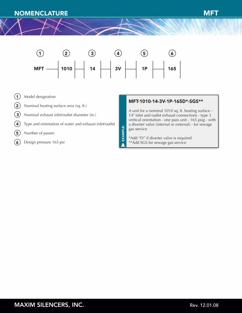
MFT 1010 14 3V 1P 165
2 3 4 5 6
Model designation
Nominal heating surface area (sq. ft.)
Nominal exhaust inlet/outlet diameter (in.)
Type and orientation of water and exhaust inlet/outlet Number of passes
Design pressure 165 psi
1
2
3
4
5
6 EX
AM
PLE
:
MFT-1010-14-3V-1P-165D*-SGS**
A unit for a nominal 1010 sq. ft. heating surface - 14" inlet and outlet exhaust connections - type 3 vertical orientation - one pass unit - 165 psig - with a diverter valve (internal or external) - for sewage gas service
*Add “D” if diverter valve is required**Add SGS for sewage gas service
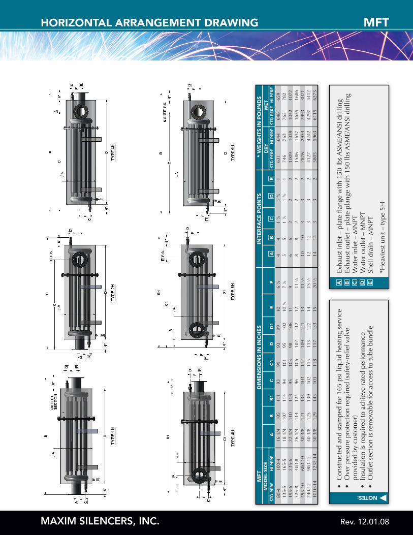
MFTHORIZONTAL ARRANGEMENT DRAWING
MAXIM SILENCERS, INC. Rev. 12.01.08
NOTES:
•
Con
stru
cted
and
sta
mpe
d fo
r 16
5 ps
i liq
uid
heat
ing
serv
ice
•
Ove
r pr
essu
re p
rote
ctio
n re
quir
ed (s
afet
y-re
lief v
alve
prov
ided
by
cust
omer
)•
In
sula
tion
is r
equi
red
to a
chie
ve r
ated
per
form
ance
•
Out
let s
ectio
n is
rem
ovab
le fo
r ac
cess
to tu
be b
undl
e
MFT
MO
DE
L-SI
ZE
DR
YW
ET
AA
STD
PE
RF
STD
PE
RF
BB
HI P
ER
FH
I PE
RF
HI P
ER
FST
D P
ER
FB
1C
CD
DE
EC
1D
1F
DIM
EN
SIO
NS
IN IN
CH
ES
INTE
RFA
CE
PO
INTS
* W
EIG
HTS
IN P
OU
ND
S
80-4
10
0-4
16 1
/4
105
111
93
99
93
99
10
6 3 ⁄8
4
4 1
1 ⁄2
1 1 ⁄2
1
63
1
644
64
6
659
135-
5 16
5-5
18 1
/4
107
114
94
101
95
102
10 1 ⁄2
7
1 ⁄4
5 5
1 1 ⁄2
1
1 ⁄2
1
746
76
3
765
78
219
5-6
235-
6 22
1/4
11
0 11
8 95
10
3 98
10
6 11
9
6 6
2 2
2 10
09
1039
10
42
1072
325-
8 40
0-8
26 1
/4
114
124
96
106
102
112
12
11 1 ⁄8
8
8 2
2 2
1586
16
37
1635
16
8649
5-10
60
0-10
30
3/8
12
1 13
3 10
4 11
2 10
9 12
1 13
11
1 ⁄2
10
10
3 3
2 28
76
2954
29
93
3071
740-
12
900-
12
40 3
/8
125
139
102
115
113
127
14
15 1 ⁄2
12
12
3
3 2
4127
42
42
4297
44
1210
10-1
4 12
35-1
4 50
3/8
12
9 14
5 10
3 11
8 11
7 13
3 15
20
1 ⁄2
14
14
3 3
2 58
05
5963
61
15
6273
Exha
ust i
nlet
– p
late
flan
ge w
ith 1
50 lb
s A
SME/
AN
SI d
rilli
ngEx
haus
t out
let –
pla
te p
lang
e w
ith 1
50 lb
s A
SME/
AN
SI d
rilli
ngW
ater
inle
t – M
NPT
Wat
er o
utle
t – M
NPT
Shel
l dra
in –
MN
PT
*Hea
vies
t uni
t – ty
pe 5
H
A B C D E
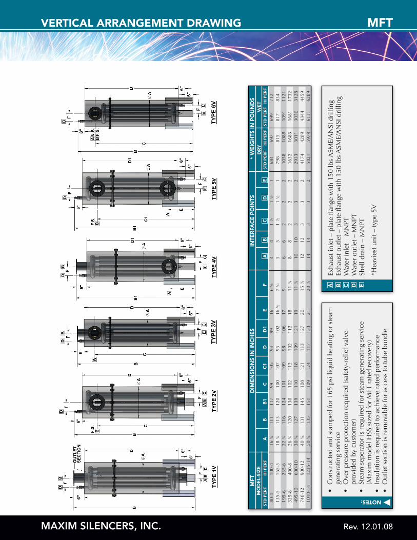
VERTICAL ARRANGEMENT DRAWING
MAXIM SILENCERS, INC. Rev. 12.01.08
MFTNOTES:
•
Con
stru
cted
and
sta
mpe
d fo
r 16
5 ps
i liq
uid
heat
ing
or s
team
gene
ratin
g se
rvic
e•
O
ver
pres
sure
pro
tect
ion
requ
ired
(saf
ety-
relie
f val
ve
pr
ovid
ed b
y cu
stom
er)
•
Stea
m s
eper
ator
is r
equi
red
for
stea
m g
ener
atin
g se
rvic
e
(M
axim
mod
el H
SS s
ized
for
MFT
rat
ed r
ecov
ery)
•
Insu
latio
n is
req
uire
d to
ach
ieve
rat
ed p
erfo
rman
ce•
O
utle
t sec
tion
is r
emov
able
for
acce
ss to
tube
bun
dle
Exha
ust i
nlet
– p
late
flan
ge w
ith 1
50 lb
s A
SME/
AN
SI d
rilli
ngEx
haus
t out
let –
pla
te fl
ange
with
150
lbs
ASM
E/A
NSI
dri
lling
Wat
er in
let –
MN
PTW
ater
out
let –
MN
PTSh
ell d
rain
– M
NPT
*Hea
vies
t uni
t – ty
pe 5
V
A B C D E
80-4
10
0-4
16 1 ⁄4
11
1 11
7 99
10
5 93
99
16
6
3 ⁄8
4 4
1 1 ⁄2
1
1 ⁄2
1 68
4
697
69
9
712
135-
5 16
5-5
18 1 ⁄4
11
3 12
0 10
0 10
7 95
10
2 16
1 ⁄2
7 1 ⁄4
5
5 1
1 ⁄2
1 1 ⁄2
1
798
81
5
817
83
419
5-6
235-
6 22
1 ⁄4
116
124
101
109
98
106
17
9 6
6 2
2 2
1058
10
88
1091
11
2132
5-8
400-
8 26
1 ⁄4
120
130
102
112
102
112
18
11 1 ⁄8
8
8 2
2 2
1632
16
83
1681
17
3249
5-10
60
0-10
30
3 ⁄8
127
139
110
118
109
121
19
11 1 ⁄2
10
10
3
3 2
2933
30
11
3050
31
2874
0-12
90
0-12
40
3 ⁄8
131
145
108
121
113
127
20
15 1 ⁄2
12
12
3
3 2
4174
42
89
4344
44
5910
10-1
4 12
35-1
4 50
3 ⁄8
135
151
109
124
117
133
21
20 1 ⁄2
14
14
3
3 2
5821
59
79
6131
62
89
MFT
MO
DE
L-SI
ZE
DR
YA
AST
D P
ER
FST
D P
ER
FB
BH
I PE
RF
HI P
ER
FH
I PE
RF
STD
PE
RF
B1
CC
DD
EE
C1
D1
F
DIM
EN
SIO
NS
IN IN
CH
ES
INTE
RFA
CE
PO
INTS
WE
T*
WE
IGH
TS IN
PO
UN
DS