Boat Trailer Aluminum I-Beam - FULL SIZEems fl ems nc ems tx ems mo (tx) °°°) °°°) °°°) °°°) °°°)
Upload
vuongtuyenCategory
view
218download
2
EMS Educational Material_001
3 The trouble check of TPS signal It is difficult to repair troubles related to TPS(Throttle Position Sensor). In order to solve trouble
like this, you must understand basic principle. That is so helpful for counteraction. Hereafter we
will explain cause of trouble and counteraction with trouble type, which is happened many times
in field.
If you want to solve a certain problem exactly, you have to understand principle. If not, you don’t
repair trouble of vehicle easily and it is not helpful for you.
1. Troubles 1. Malfunction of TPS sensor
Cause of trouble Malfunction TPS or wiring circuit failure(Signal, Ground and Reference)
Counter action
Healing by cause of trouble 1.1 TPS replace 1.2 Wiring circuit repair
Engine state
The surging is taken place when acceleration and RPM cycling is happened when recovering to idle.
Signal view
03_Throttle Position Sensor 1/19

EMS Educational Material_001
2 TPS signal is always high (Above 4.7 V)
Cause of trouble
Trouble detection more than one of the followings 2.1 Abnormal TPS (High resistance : Above 1MΩ ) 2.2 TPS bad connecting 2.3 Bad connecting of TPS ground 2.4 Bad connecting of TPS reference line (5V )
Counter action
Healing by cause of trouble 2.1 TPS replace 2.2 TPS wiring circuit repair
Engine state
The surging is taken place when acceleration and RPM cycling is happened when recovering to idle.
Signal view
In case that TPS signal line is broken, TPS voltage is close to 5[volt] because TPS signal line is connected with 5[volt] power supply line of “Full up” resistance.
03_Throttle Position Sensor 2/19

EMS Educational Material_001
3 TPS signal is always low(Below 0.2 V).
Cause of trouble
Trouble detection more than one of the followings 3.1 Abnormal TPS (Abnormal sensing) 3.2 Bad connecting of TPS signal line or short to ground 3.3 TPS reference line (5V) short to ground
Counter action
Healing by cause of trouble 3.1 TPS replace 3.2 TPS wiring circuit repair
Engine state
The surging is taken place when acceleration and RPM cycling is happened when recovering to idle.
Signal view
In idle state(Case of throttle valve closing), TPS signal is from 0.6 to 2.0[volt] range. And in case that TPS signal line is broken, TPS voltage is close to 5[volt] because TPS signal line is connected with 5[volt] power supply line of “Full up” resistance.
03_Throttle Position Sensor 3/19

EMS Educational Material_001
4. Abnormal TPS signal by Micro cut-off
Cause of trouble
Trouble detection more than one of the followings :Occur trouble during very short time(Below 100usec) and TPS adaptation value is very small at the moment 4.1 Abnormal TPS (Abnormal sensing) 4.2 TPS bad connecting
Counter action
Reset adaptation value after cleaning connector. Nevertheless, if the problem is still happened, make shielded wire as below picture.
< Reference > Engine stall or vibration with idle engine state is expected. But don’t need to repair it if engine operation is normal.
Engine state
The severe engine vibration is occurred in idle state and sometimes engine stall is taken place. In case of floating occurrence, idle RPM is not returned to target.
Signal view
03_Throttle Position Sensor 4/19
EMS Educational Material_001
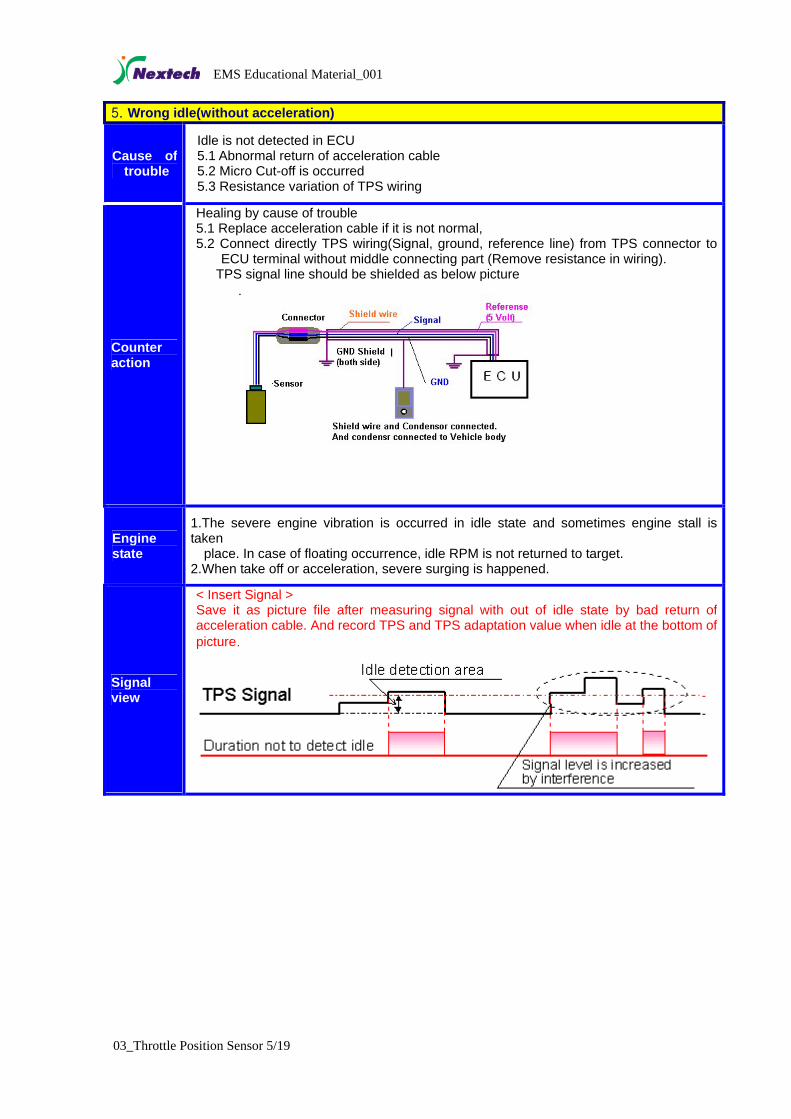
5. Wrong idle(without acceleration)
Cause of trouble
Idle is not detected in ECU 5.1 Abnormal return of acceleration cable 5.2 Micro Cut-off is occurred 5.3 Resistance variation of TPS wiring
Counter action
Healing by cause of trouble 5.1 Replace acceleration cable if it is not normal, 5.2 Connect directly TPS wiring(Signal, ground, reference line) from TPS connector to
ECU terminal without middle connecting part (Remove resistance in wiring). TPS signal line should be shielded as below picture
.
Engine state
1.The severe engine vibration is occurred in idle state and sometimes engine stall is taken place. In case of floating occurrence, idle RPM is not returned to target. 2.When take off or acceleration, severe surging is happened.
Signal view
< Insert Signal > Save it as picture file after measuring signal with out of idle state by bad return of acceleration cable. And record TPS and TPS adaptation value when idle at the bottom of picture.
03_Throttle Position Sensor 5/19

EMS Educational Material_001
6. TPS noise detection with idle state
Cause of trouble
ECU recognizes continuously acceleration/deceleration for a moment. 6.1 It is influenced by external electric from TPS wiring
Counter action
6.1 Shield wiring of ignition system and keep away from TPS wiring. 6.2 Connect directly after shielding TPS wiring(Signal, ground, reference line) from TPS
connector to ECU terminal without middle connecting part. TPS signal line should be shielded as below picture.
< TPS signal line / TPS ground line / TPS reference line >
6.3 In case of connecting with TCU, separate it TCU 6.4 In case of connecting with vehicle sensor and other sensors, Do like 6.2
Engine state
1. The severe engine vibration is occurred in idle state and sometimes engine stall is taken place. In case of floating occurrence, engine is not returned to target idle RPM. 2. When take off or acceleration, severe surging is happened. 3. The emission may be increased too much in idle state.
Signal view
03_Throttle Position Sensor 6/19

EMS Educational Material_001
2. Field example < Example 1 > The problem by noise
Vehicle : Matiz, Odometer : 4,800Km
Problem description : RPM cycling is sometimes taken place in idle state with engine
vibration. And a lot of CO emission(1.7%) comes from exhaust gas in idle state.
Cause : RPM cycling is taken place because ECU doesn’t recognize idle state by noise
detection of TPS signal. Whenever noise is detected, ECU recognizes it as working rapidly
acceleration pedal. And it is cause of rich injection control as adding fuel correction when
acceleration
Signal measurement:
< Rich injection control by fuel correction when acceleration >
< Amplification of noise signal : ECU doesn’t recognize idle state >
Explanation : The noise is not occurred after separating TPS signal line from TCU connecting.
But if it is TPS signal line which must be used with TCU connecting, noise may be reduced as
separating TCU from connecting part as far as possible.
Enlargement of application : If noise is occurred in TPS signal, find what is connected with
TPS signal and ground line. And check noise after separating it. If noise is reduced, remove
connecting part. But if removal is impossible, find point that the lowest noise is detected as
moving connecting part. Nevertheless, if noise is not decreased, find point that the lowest noise
is detected as moving ground line and connect it. It may be implemented by shield line. <
03_Throttle Position Sensor 7/19
EMS Educational Material_001
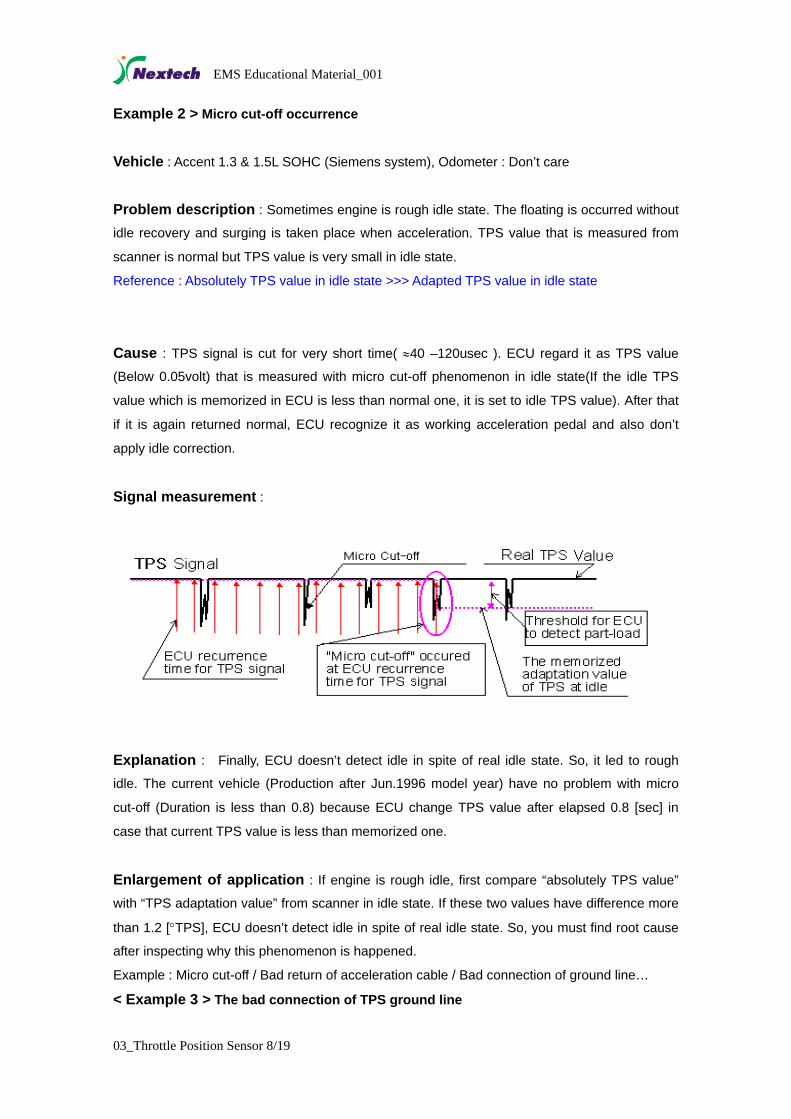
Example 2 > Micro cut-off occurrence
Vehicle : Accent 1.3 & 1.5L SOHC (Siemens system), Odometer : Don’t care
Problem description : Sometimes engine is rough idle state. The floating is occurred without
idle recovery and surging is taken place when acceleration. TPS value that is measured from
scanner is normal but TPS value is very small in idle state.
Reference : Absolutely TPS value in idle state >>> Adapted TPS value in idle state
Cause : TPS signal is cut for very short time( ≈40 –120usec ). ECU regard it as TPS value
(Below 0.05volt) that is measured with micro cut-off phenomenon in idle state(If the idle TPS
value which is memorized in ECU is less than normal one, it is set to idle TPS value). After that
if it is again returned normal, ECU recognize it as working acceleration pedal and also don’t
apply idle correction.
Signal measurement :
Explanation : Finally, ECU doesn’t detect idle in spite of real idle state. So, it led to rough
idle. The current vehicle (Production after Jun.1996 model year) have no problem with micro
cut-off (Duration is less than 0.8) because ECU change TPS value after elapsed 0.8 [sec] in
case that current TPS value is less than memorized one.
Enlargement of application : If engine is rough idle, first compare “absolutely TPS value”
with “TPS adaptation value” from scanner in idle state. If these two values have difference more
than 1.2 [°TPS], ECU doesn’t detect idle in spite of real idle state. So, you must find root cause
after inspecting why this phenomenon is happened.
Example : Micro cut-off / Bad return of acceleration cable / Bad connection of ground line…
< Example 3 > The bad connection of TPS ground line
03_Throttle Position Sensor 8/19
EMS Educational Material_001
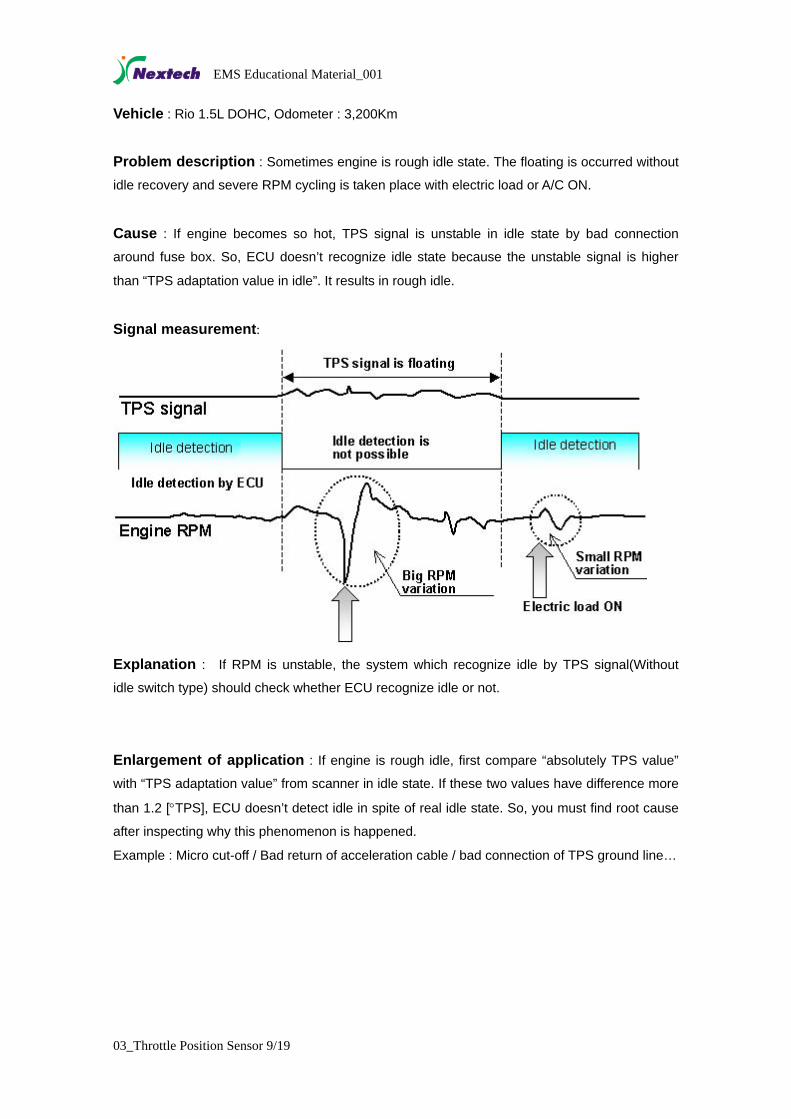
Vehicle : Rio 1.5L DOHC, Odometer : 3,200Km
Problem description : Sometimes engine is rough idle state. The floating is occurred without
idle recovery and severe RPM cycling is taken place with electric load or A/C ON.
Cause : If engine becomes so hot, TPS signal is unstable in idle state by bad connection
around fuse box. So, ECU doesn’t recognize idle state because the unstable signal is higher
than “TPS adaptation value in idle”. It results in rough idle.
Signal measurement:
Explanation : If RPM is unstable, the system which recognize idle by TPS signal(Without
idle switch type) should check whether ECU recognize idle or not.
Enlargement of application : If engine is rough idle, first compare “absolutely TPS value”
with “TPS adaptation value” from scanner in idle state. If these two values have difference more
than 1.2 [°TPS], ECU doesn’t detect idle in spite of real idle state. So, you must find root cause
after inspecting why this phenomenon is happened.
Example : Micro cut-off / Bad return of acceleration cable / bad connection of TPS ground line…
03_Throttle Position Sensor 9/19

EMS Educational Material_001
3. Location of TPS
< TPS : Throttle Position Sensor >
03_Throttle Position Sensor 10/19
EMS Educational Material_001
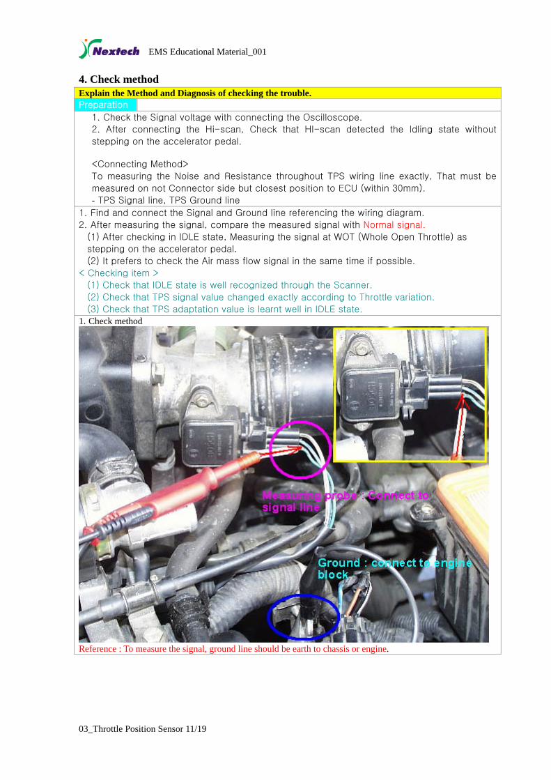
4. Check method Explain the Method and Diagnosis of checking the trouble. Preparation 1. Check the Signal voltage with connecting the Oscilloscope.
2. After connecting the Hi-scan, Check that HI-scan detected the Idling state without
stepping on the accelerator pedal. <Connecting Method>
To measuring the Noise and Resistance throughout TPS wiring line exactly, That must be
measured on not Connector side but closest position to ECU (within 30mm).
- TPS Signal line, TPS Ground line 1. Find and connect the Signal and Ground line referencing the wiring diagram.
2. After measuring the signal, compare the measured signal with Normal signal.
(1) After checking in IDLE state, Measuring the signal at WOT (Whole Open Throttle) as
stepping on the accelerator pedal. (2) It prefers to check the Air mass flow signal in the same time if possible.
< Checking item >
(1) Check that IDLE state is well recognized through the Scanner.
(2) Check that TPS signal value changed exactly according to Throttle variation.
(3) Check that TPS adaptation value is learnt well in IDLE state. 1. Check method
Reference : To measure the signal, ground line should be earth to chassis or engine.
03_Throttle Position Sensor 11/19

EMS Educational Material_001
5. Wave analysis
Check the output voltage according to the pedal opening degree.
< Spec. : Specification which used during development period >
< Measurement : Measure the mass air flow and TPS during full acceleration from idle>
ECU recognized TPS sigal check is essential. Through the scanner, TPS value vs. TPS
adapted value check is required during idle. If TPS value is bigger (around 1.2) than
adapted value, engine idle can be unstable due to ECU not recognized idle status.
03_Throttle Position Sensor 12/19
EMS Educational Material_001
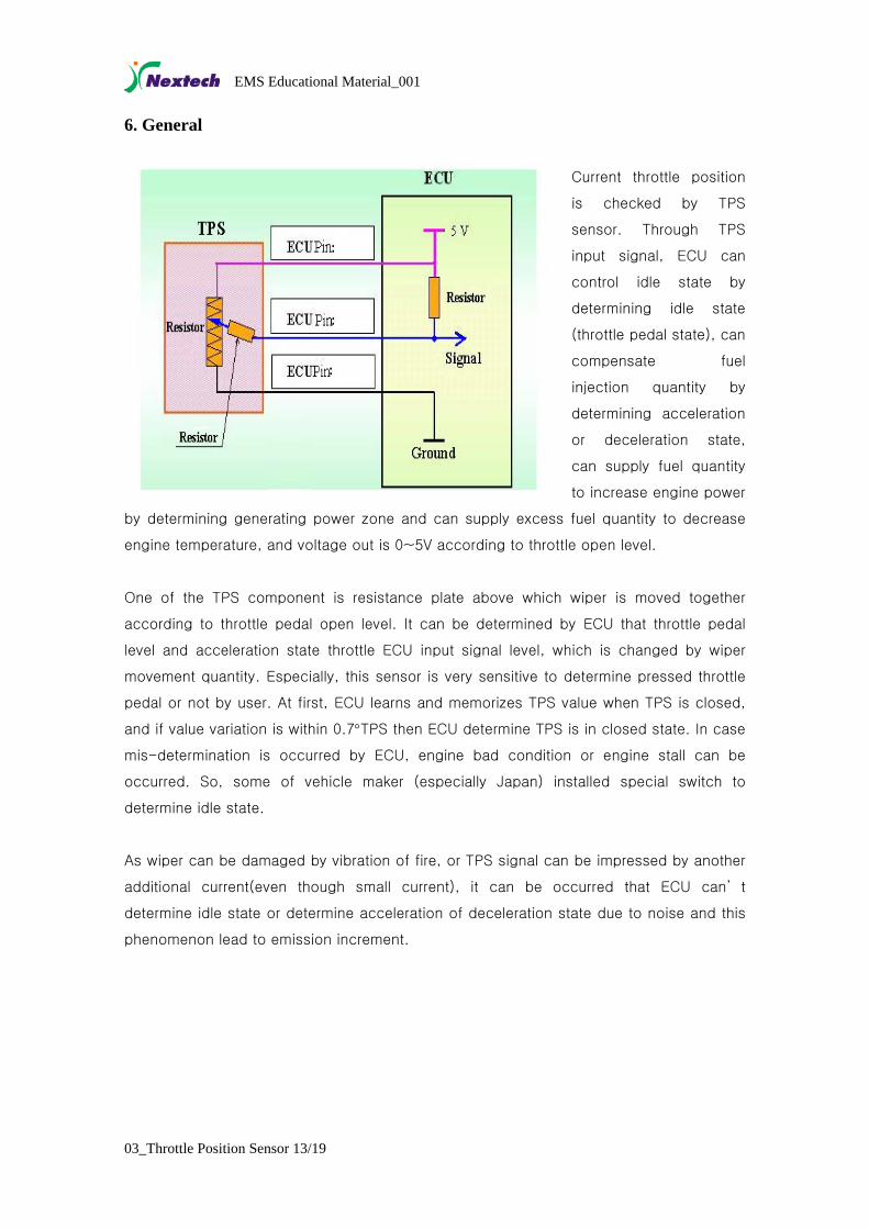
6. General
Current throttle position
is checked by TPS
sensor. Through TPS
input signal, ECU can
control idle state by
determining idle state
(throttle pedal state), can
compensate fuel
injection quantity by
determining acceleration
or deceleration state,
can supply fuel quantity
to increase engine power
by determining generating power zone and can supply excess fuel quantity to decrease
engine temperature, and voltage out is 0~5V according to throttle open level.
One of the TPS component is resistance plate above which wiper is moved together
according to throttle pedal open level. It can be determined by ECU that throttle pedal
level and acceleration state throttle ECU input signal level, which is changed by wiper
movement quantity. Especially, this sensor is very sensitive to determine pressed throttle
pedal or not by user. At first, ECU learns and memorizes TPS value when TPS is closed,
and if value variation is within 0.7°TPS then ECU determine TPS is in closed state. In case
mis-determination is occurred by ECU, engine bad condition or engine stall can be
occurred. So, some of vehicle maker (especially Japan) installed special switch to
determine idle state.
As wiper can be damaged by vibration of fire, or TPS signal can be impressed by another
additional current(even though small current), it can be occurred that ECU can’ t
determine idle state or determine acceleration of deceleration state due to noise and this
phenomenon lead to emission increment.
03_Throttle Position Sensor 13/19

EMS Educational Material_001
03_Throttle Position Sensor 14/19
EMS Educational Material_001
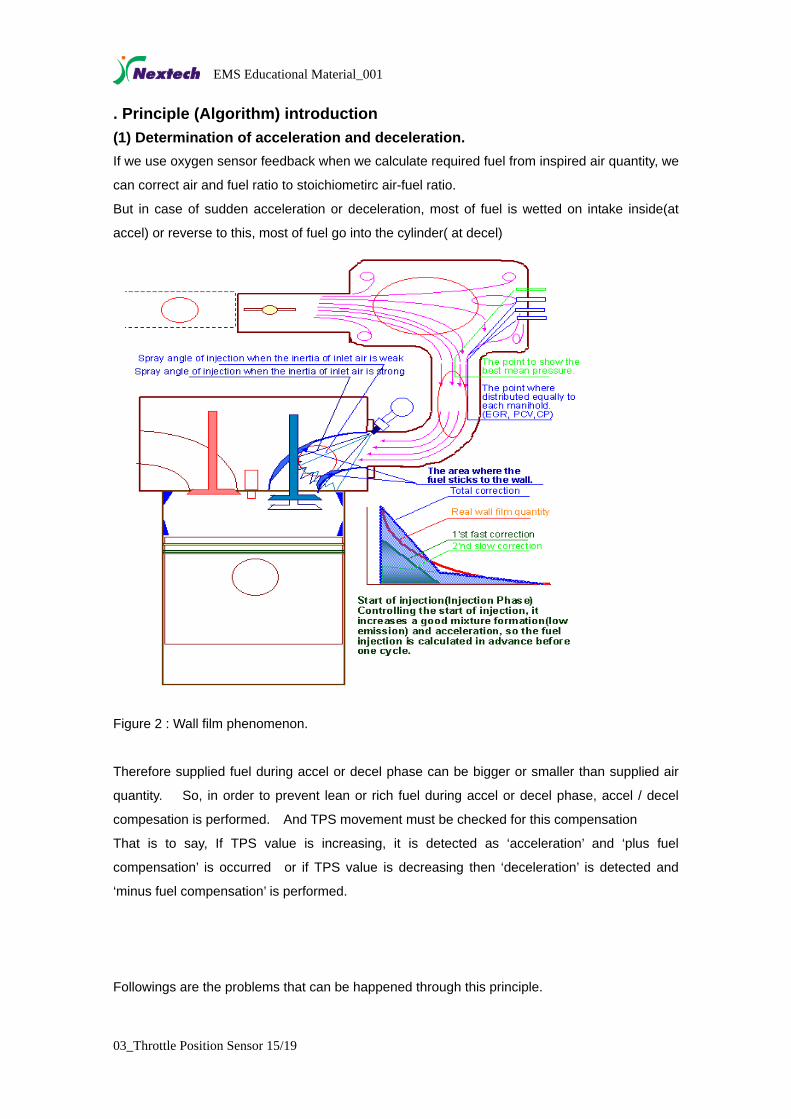
. Principle (Algorithm) introduction (1) Determination of acceleration and deceleration. If we use oxygen sensor feedback when we calculate required fuel from inspired air quantity, we
can correct air and fuel ratio to stoichiometirc air-fuel ratio.
But in case of sudden acceleration or deceleration, most of fuel is wetted on intake inside(at
accel) or reverse to this, most of fuel go into the cylinder( at decel)
Figure 2 : Wall film phenomenon.
Therefore supplied fuel during accel or decel phase can be bigger or smaller than supplied air
quantity. So, in order to prevent lean or rich fuel during accel or decel phase, accel / decel
compesation is performed. And TPS movement must be checked for this compensation
That is to say, If TPS value is increasing, it is detected as ‘acceleration’ and ‘plus fuel
compensation’ is occurred or if TPS value is decreasing then ‘deceleration’ is detected and
‘minus fuel compensation’ is performed.
Followings are the problems that can be happened through this principle.
03_Throttle Position Sensor 15/19

EMS Educational Material_001
< Trouble : Impossible to detect accel or decel. >
Throttle opening
Fuel correction
Fuel injection
Fuel without correction
Fuel correction at accelFuel correction at decel
▶Big shock or hesitation during accel or decel.
▶Insufficient acceleration response.
< Reason >
▶Ignition time is retarded to reduce acceleration shock when acceleration is detected. But if
acceleration is not detected then accel shock will be happened due to no ignition retard to
prevent accel shock.
▶Engine torque decreasing due to that additional fuel to compensate wall film during
acceleration is not supplied.
< Countermeasure >
Move TPS and check if real signal value is moving. The problem of constant signal due to line
break or short circuit can be detected by ECU self diagnosis and if you connect Hi-scan, you
can find the root cause.
(2) Determination of idle In order to keep idle engine speed during idle phase, spark time and air quantity are controlled.
If engine speed is getting higher then spark time is retarded or if engine speed is getting
decrease then spark time is advanced. Air quantity supplied to engine is feedback controlled
depending on engine by ISC valve opening.
In the past, earlier model had idle switch. At that time idle was detected when idle switch was
turned on. But now, by effort of carmaker to reduce the cost, idle is detected when TPS signal
is below certain level instead of idle switch.
From that time, Idle detection logic was developed to detect idle depend on TPS signal by
electric control unit maker. But due to the limit of this logic, many expert of electric control unit
have suffered when trouble happened and developed the logic.
ECU memorizes initial TPS signal of about 0.8-0.2V right after TPS installation as idle state.
And if TPS value is lower than first value then lower value is saved as idle state again.
If TPS output is 1.2V after TPS installation then 1.2V is saved as idle level and then if TPS
03_Throttle Position Sensor 16/19

EMS Educational Material_001
output is 1.0V then 1.0V is saved as idle level again. As the TPS value at idle is the smallest
value during normal driving, the logic is very simple.
On contrary, if TPS value is little bit high and engine speed is not so much high then idle value
of TPS is getting increase. For example, if 1.5V is output at idle speed and 1.2V is saved as
idle value then idle value of TPS is increasing by 0.05V for every 2sec. And then finally, 1.5V
is adapted as idle value.
The reason of little bit late adaptation is to avoid wrong adaptation during slight acceleration.
Above mentioned logic seems to be normal but there is one problem.
The problem I’d like to mention now was one of example that gave big headaches to the electric
control unit experts to find the reason and fix it.
I’m one of those people who insist to install idle switch but our insist were treated as a
‘nonsense’ due to cost increase.
First of all, I’d like to arrange in a row the problem from TPS and then reason and counteraction
on it.
< Problem with wrong TPS signal >
Abnormal behavior of vehicle on the filed due to limit of above mentioned logic is as following.
▶Engine rpm is unstable or engine stall after rpm oscillation during idle
▶Engine speed is high(more than 1200rpm) but never back to idle speed
▶There are big shock or low power during acceleration.
▶Emission at idle is bigger than normal ( about more than 2-3 times)
▶Big oscillation when car is driving with slight acceleration.
< Root cause >
▶If and TPS signal is suddenly goes down to 0V and adapt it as idle state and then back to
1.0V again after 1.0V has been adapted as idle state, what will be happened?
In this case, 1.0V of TPS pedal pushing is detected and will make above problem.
< Figure 3 : TPS signal micro cut off >
03_Throttle Position Sensor 17/19

EMS Educational Material_001
=> Actually, TPS signal micro cut off can be happened but the root cause is still not found out
and counteractions are just to improve connection conditions of TPS connector and to change
logic. For example, if TPS value is decreased very fast, ignore current value but use previous
value. As it is difficult to improve above problem in the filed, ECU must be change with new
improved logic.
▶ In case of that idle state is not detected due to higher signal voltage by bad TPS ground
condition TPS, engine speed must be within normal range (below 1200rpm) to adapt current
TPS value as idle data. But what if idle speed is higher than 1200rpm or what if engine is
stalled? In that case, as TPS have no chance to learn idle state, above mentioned problem
will be happened intermittently (especially with overheated engine, or with hot weather ).
< Figure 4: TPS signal is floating by external influence >
=> In fact, if idle detection is failed during idle state, engine speed can be higher than idle speed.
Because, spark advance is set to MBT(Maximum spark advance for Best Torque ) out of idle
area. Even though air quantity to the cylinder is same, engine speed increase with higher
spark angle. (Remark: 10-15rpm per 1deg of spark angle.). Therefore if TPS value is bigger
than adapted value and engine speed is higher than idle then ECU detect as pushing throttle
pedal. In some cases, engine can be stalled. In this case, besides of engine speed increase
by spark advance, engine stall can be happened due to no compensation for the electric load.
The counteraction for this is that if other component uses same ground line with TPS, then
separate TPS ground line and ground it separately. And check TPS connector condition.( best
action is to connect all TPS line : Signal, ground and reference line from TPS to ECU directly).
▶ In case of noise on TPS signal, how ECU can avoid wrong detection of this noise signal as
real throttle pedal movement? What if accel and decel compensation is happened by this
noise?
In this case, following problem will be happened as shown figure 5.
03_Throttle Position Sensor 18/19

EMS Educational Material_001
03_Throttle Position Sensor 19/19
< Figure 5: TPS noise >
=> This problem also can be happened well. Especially, if TPS signal is used for other
functions(TCU ), this problem can be happened.
In that case, it do not give any influence to the driver but high emission or engine noise at idle
can be occurred.
The counteraction for this problem is to connect all TPS line : Signal, ground and reference line
from TPS to ECU directly.
But if TPS line is shared with TCU (Transmission Control Unit) then find good ground
connection location between ECU and TCU where shows less noise. ( This action is for car
body electronic engineer but if there are many accessories installed by owner(audio…), it is
same )
Above mentioned three contents are problem type made headaches before.
Then how many time this problem will be happened?
Actually, we can think that there is very seldom. But we may skip this problem without
recognition. So, it is need to approach the problem with understanding of principle.