DETERMINATION OF DRYNESS METHODS OF … OF DRYING OUT ... measured with the transformer cold is...
21
I.L. 0-621 INSTRUCTIONS DETERMINATION OF DRYNESS and METHODS OF DRYING OUT All transformers are dry when they leave the factory, but since they may absorb more or less moisture during shipment and storage, they should not be put into service until it has been determined that the oil and insulation are dry enough for safe operation. The higher the voltage, the more chances there are of trouble from moisture, and the greatest care should be exercised to make sure that the moisture is practically eliminated. DRYNESS OF OIL AND WINDINGS When a transformer has been shipped assembled in its case with the oil, four or five samples of oil should be drawn from e bottom of the case and tested. If the average of these tests shows a break- down value of not less than 22,000 volts on a standard 1/10+ gap test-cup, the insulaon and oil are in a satisfactory condition for service. If the average breakdown value is less than 22,000 volts, the oil must be dried. Whether the windings must also be dried should be determined as described under "Insulation Resistance". If the insulaon resistance is of the proper value, drying of the windings is unnecessary and the transformer may be put into service. When a transformer is shipp without either oil or dry nitrogen gas, drying out will be necessary, except in the cases of transformers 500 kva, and under, and of less than 7500 volʦ. These latter transformers should be tested for dryness before being put into service. There is no absolute method of determing when the insulation of a transformer is dry, but proper measurements of insulation resistance will serve as an approximate indication of its condion. Iulation Resistance. Insulaon resistance measured with the transformer cold is greater than when measured with it hot and is also greater out of oil than when immersed in oil. Therefore, in order to determine the condition of the insulation all of the measured values must be reduced to a fixed set of SUPERSEDES I.L. 47-<0-tOC conditions. The reference conditions are a temper- ature of 20°C and with the transformer filled with dry transformer oil in good condition. For these conditions the minimum sasfactory insulation resistance corresponding to each nominal line to line voltage class is given. Corrected measured values lower than those tabulat indicate that the transformer should be dried before energizing (See Figure 1). Minimum Insulation Resistance in Oll at 20°C L·L VOLTAGE MEGOHMS L·L VOLTAGE MEGOHMS CLASS KV CLASS KV 1.2 32 92 2480 2.5 68 115 31 5 135 138 3720 8.66 230 161 4350 15 410 196 Ȓ0 25 670 230 6200 34.5 930 287 7750 46 1240 345 93 69 18< I FIG. 1 Insulation Resistance Tempeate Coeetion TRANSFORMER TEMPERATURE oc 95 90 85 80 75 70 65 60 55 50 45 40 CORRECTION FACTOR 89.0 66.0 49.0 36.2 26.8 I 20.0 14.8 11.0 I 8.1 6.0 I 4.5 3.3 ,, TRANSFORMER I CORRECTION TEMPERATURE ac FACTOR 35 2.5 30 1.8 25 1.3 20 1.0 15 0.73 10 0.54 5 0.40 0 0.30 - 5 0.22 - 10 0.16 - 15 0.12 FIG. 2 JULY, 1`0 www . ElectricalPartManuals . com
Transcript of DETERMINATION OF DRYNESS METHODS OF … OF DRYING OUT ... measured with the transformer cold is...

I.L. 48-628-1
INSTRUCTIONS
DETERMINATION OF DRYNESS
and
METHODS OF DRYING OUT
All transformers are dry when they leave the factory, but since they may absorb more or less moisture during shipment and storage, they should
not be put into service until it has been determined that the oil and insulation are dry enough for safe operation. The higher the voltage, the more chances there are of trouble from moisture, and the greatest care should be exercised to make sure that the
moisture is practically eliminated.
DRYNESS OF OIL AND WINDINGS
When a transformer has been shipped assembled in its case with the oil, four or five samples of oil
should be drawn from the bottom of the case and tested. If the average of these tests shows a break
down value of not less than 22,000 volts on a standard 1/1011 gap test-cup, the insulation and oil
are in a satisfactory condition for service. If the average breakdown value is less than 22,000 volts,
the oil must be dried. Whether the windings must
also be dried should be determined as described under "Insulation Resistance". If the insulation resistance is of the proper value, drying of the windings is unnecessary and the transformer may be put into service.
When a transformer is shipped without either oil or dry nitrogen gas, drying out will be necessary, except in the cases of transformers 500 kva, and under, and of less than 7500 volts. These latter transformers should be tested for dryness before being put into service.
There is no absolute method of determining when the insulation of a transformer is dry, but proper measurements of insulation resistance will serve as
an approximate indication of its condition.
Insulation Resistance. Insulation resistance measured with the transformer cold is greater than
when measured with it hot and is also greater out of
oil than when immersed in oil. Therefore, in order
to determine the condition of the insulation all of the
measured values must be reduced to a fixed set of
SUPERSEDES I.L. 47-600-tOC
conditions. The reference conditions are a temper
ature of 20°C and with the transformer filled with
dry transformer oil in good condition. For these conditions the minimum satisfactory insulation resistance corresponding to each nominal line to
line voltage class is given. Corrected measured values lower than those tabulated indicate that the transformer should be dried before energizing
(See Figure 1).
Minimum Insulation Resistance in Oll at 20°C
L·L VOLTAGE MEGOHMS
L·L VOLTAGE MEGOHMS CLASS KV CLASS KV
1.2 32 92 2480 2.5 68 115 3100 5 135 138 3720 8.66 230 161 4350
15 410 196 5300 25 670 230 6200 34.5 930 287 7750 46 1240 345 9300 69 1860
I
FIG. 1
Insulation Resistance Tempel'atUI'e Col'l'eetion
TRANSFORMER TEMPERATURE oc
95 90 85 80 75
70 65 60 55 50
45 40
CORRECTION FACTOR
89.0 66.0 49.0 36.2 26.8
I
20.0 14.8 11.0
I 8.1 6.0 I
4.5 3.3
,,
TRANSFORMER I CORRECTION TEMPERATURE ac FACTOR
35 2.5 30 1.8 25 1.3 20 1.0 15 0.73
10 0.54 5 0.40 0 0.30
- 5 0.22 - 10 0.16
- 15 0.12
FIG. 2
JULY, 1960 www . El
ectric
alPar
tMan
uals
. com

DETERMINATION OF DRYNESS---------------------
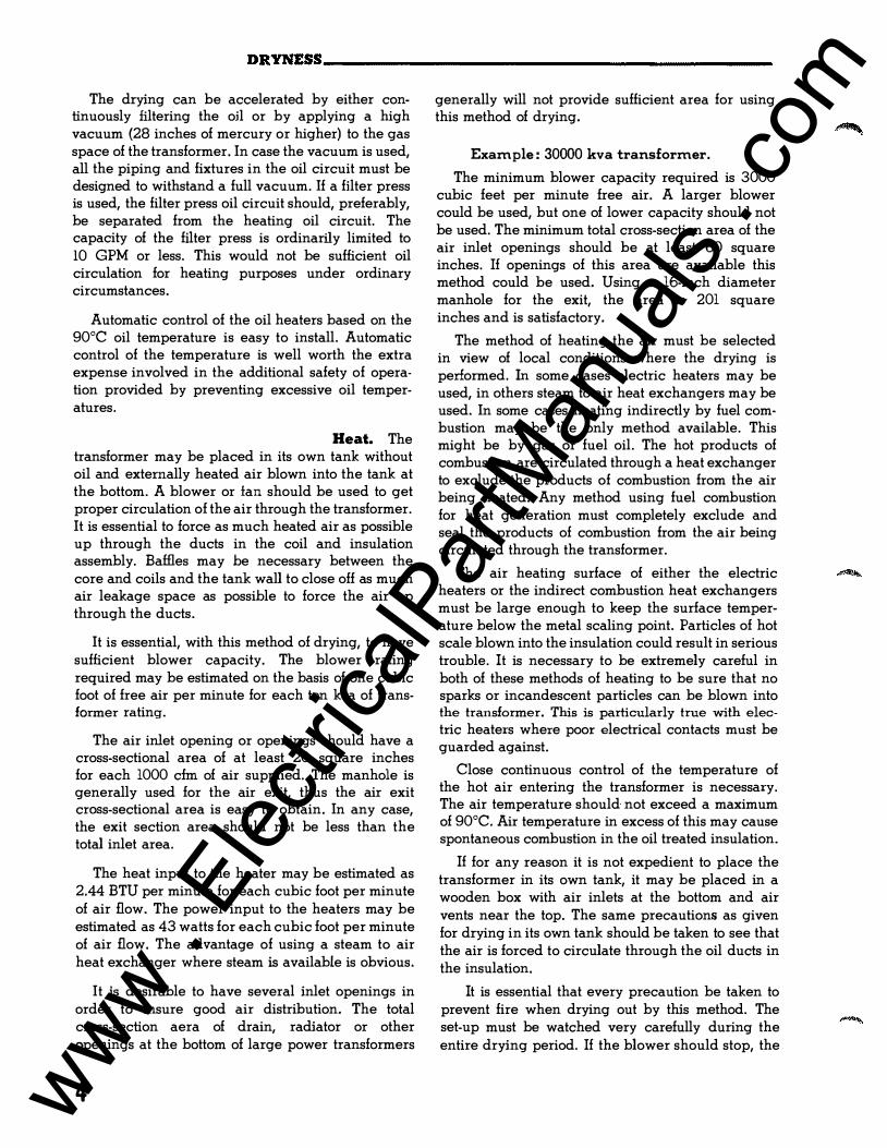
The drying can be accelerated by either continuously filtering the oil or by applying a high vacuum (28 inches of mercury or higher) to the gas space of the transformer. In case the vacuum is used, all the piping and fixtures in the oil circuit must be designed to withstand a full vacuum. If a filter press is used, the filter press oil circuit should, preferably, be separated from the heating oil circuit. The capacity of the filter press is ordinarily limited to 10 GPM or less. This would not be sufficient oil circulation for heating purposes under ordinary circumstances.
Automatic control of the oil heaters based on the gooc oil temperature is easy to install. Automatic control of the temperature is well worth the extra expense involved in the additional safety of operation provided by preventing excessive oil temperatures.
2. Drying Out by External Heat. The transformer may be placed in its own tank without oil and externally heated air blown into the tank at the bottom. A blower or tan should be used to get proper circulation of the air through the transformer. It is essential to force as much heated air as possible up through the ducts in the coil and insulation assembly. Baffles may be necessary between the core and coils and the tank wall to close off as much air leakage space as possible to force the air up through the ducts.
It is essential, with this method of drying, to have sufficient blower capacity. The blower rating required may be estimated on the basis of one cubic foot of free air per minute for each ten kva of transformer rating.
The air inlet opening or openings should have a cross-sectional area of at least 20 square inches for each 1000 cfm of air supplied. The manhole is generally used for the air exit, thus the air exit cross-sectional area is easy to obtain. In any case, the exit section area should not be less than the total inlet area.
The heat input to the heater may be estimated as 2.44 BTU per minute for each cubic foot per minute of air flow. The power input to the heaters may be estimated as 43 watts for each cubic foot per minute of air flow. The advantage of using a steam to air heat exchanger where steam is available is obvious.
It is desirable to have several inlet openings in order to insure good air distribution. The total cross-section aera of drain, radiator or other openings at the bottom of large power transformers
generally will not provide sufficient area for using this method of drying.
Example: 30000 kva transformer.
The minimum blower capacity required is 3000 cubic feet per minute free air. A larger blower could be used, but one of lower capacity should not be used. The minimum total cross-section area of the air inlet openings should be at least 60 square inches. If openings of this area are available this method could be used. Using a 16-inch diameter manhole for the exit, the area is 201 square inches and is satisfactory.
The method of heating the air must be selected in view of local conditions where the drying is performed. In some cases electric heaters may be used, in others steam to air heat exchangers may be used. In some cases heating indirectly by fuel combustion may be the only method available. This might be by gas or fuel oil. The hot products of combustion are circulated through a heat exchanger to exclude the products of combustion from the air being heated. Any method using fuel combustion for heat generation must completely exclude and seal the products of combustion from the air being circulated through the transformer.
The air heating surface of either the electric heaters or the indirect combustion heat exchangers must be large enough to keep the surface temperature below the metal scaling point. Particles of hot scale blown into the insulation could result in serious trouble. It is necessary to be extremely careful in both of these methods of heating to be sure that no sparks or incandescent particles can be blown into the transformer. This is particularly true with electric heaters where poor electrical contacts must be guarded against.
Close continuous control of the temperature of the hot air entering the transformer is necessary. The air temperature should not exceed a maximum of 90°C. Air temperature in excess of this may cause spontaneous combustion in the oil treated insulation.
If for any reason it is not expedient to place the transformer in its own tank, it may be placed in a wooden box with air inlets at the bottom and air vents near the top. The same precautions as given for drying in its own tank should be taken to see that the air is forced to circulate through the oil ducts in the insulation.
It is essential that every precaution be taken to prevent fire when drying out by this method. The set-up must be watched very carefully during the entire drying period. If the blower should stop, the www .
Elec
tricalP
artM
anua
ls . c
om

DETERMINATION OF DRYNESS------------------------------------·�·L---�-6-��1
heater must be shut off at once to prevent severe overheating. Do not try to accelerate the heating by circulating current in the transformer windings. The transformers are designed to be cooled by a liquid. The heat generated in the windings by circulating current with the assembly in air may allow extreme temperatures to develop and damage the windings and insulation. Automatic temperature control and complete interlocking of blower and heater controls are desirable. The interlocking should be such that failure of control voltages, failure of blower power or failure of the heat source will completely shut down the process. A ldilure resulting in shutdown should require manual restarting of the equipment. The advantage of automatic control in obtaining satisfactory drying using this method cannot be overemphasized.
3. D:rying Out by Heating and Applying Vacuum. This is a combination of heating and vacuum drying that will give rapid, thorough drying. The transformer in its own tank is heated by Method 1 or 2, until the winding temperature measured by resistance is 80"C to 90"C. The sources of heat are then regulated to maintain this temperature for at least 24 hours in order to have the transformer uniformly and thoroughly heated. The sources of heat are then shut off. If Method 1 is used, remove the oil. The transformer tank is sealed. A vacuum is applied to the transformer tank through the upper filter press or other connection in the top of the tank. The vacuum should reduce the pressure to as low a value as possible. The highest vacuum permitted by the tank design is stated on the instruction plate. The pressure should not be reduced below that allowed by the instruction plate statement. If the instruction plate does not give this information, the Westinghouse Electric Corporation, Sharon, Pennsylvania, should be consulted before applying any vacuum to the tank. In the case of full-vacuum tanks the evacuating equipment should be capable of producing a continuous vacuum of at least 28 inches of mercury in the transformer tank. The rate of removal of moisture is increased by the use of a high vacuum with the corresponding depression of the boiling point of water.
The vacuum is maintained by continuous pumping until the temperature of the windings drops about 40"C measured by resistance. At this point the pumping is discontinued, the vacuum is released and the heating resumed to bring the windings again up to 80" to 90"C. The insulation resistance is then measured to check the progress of the drying. The process described above is then repeated until
the insulation-resistance-versus-drying time curve indicates that the windings and insulation are dry.
The number of heating and vacuum drying cycles necessary will depend upon the amount of insulation to be dried and on its moisture content. The minimum number of drying cycles will be at least three, the maximum may be as many as seven or more complete cycles in extreme cases. Drying time will require from one to two or more weeks depending on the number of drying cycles necessary.
Drying may be accelerated in Method 1 by obtaining more uniform heat distribution in the insulation where facilities are available for readily transferring and storing the oil in the transformer.
The procedure is as follows: The transformer, in its own tank and filled to the normal oil level, is heated by circulating full load or 11.4 times full load current through the full windings as described in Method 1. Self-cooled units with radiators may be heated by closing the radiator valves on all except 2 or 3 radiators. These valves are left open to allow oil circulation through the transformer thereby obtaining more uniform heating of the insulation by the hot oil. Forced-oil-cooled units should have at least one oil pump running.
The temperature of the windings should not be allowed to exceed 80" to 90"C as measured by winding resistance. If check measurements during the heating period indicate that this temperature range will be overshot, the current should be reduced.
Top oil temperature serves as a good indication of the heating of the internal parts of a transformer. A constant value of top oil temperature indicates that the heating for a constant input has reached an equilibrium condition. Thus, after the top oil temperature has been constant for four hours and the winding temperature constant in the range of 80" to 90"C, the heating may be assumed to have reached an equilibrium condition. The current is then shut off and the oil transferred from the transformer to the storage tank as rapidly as possible. The insulation resistance is measured and the tank sealed. Vacuum is then applied as previously described.
When the temperature of the windings as measured by resistance drops to about 40"C the oil is allowed to flow back into the transformer without releasing the vacuum. The vacuum increases the rate of oil transfer but considerable care is necessary to prevent oil from being drawn over into the vacuum line. Extreme care should be used in
5 www . El
ectric
alPar
tMan
uals
. com

DETERMINATION 01' DRYNESS---------------------
this regard if a reciprocating type of vacuum pump is being used as they have very small clearance compared to air compressors. A slight amount of oil in the cylinder may result in a blown gasket, fractured or blown cylinder head.
The vacuum is released after the transformer is filled to the normal oil level and the heating cycle started. If facilities are available for maintaining an oil temperature of about 90°C during the storage period the heating cycle of the transformer will be shortened.
DRYING OUT PROCEDURE
Time Requked. There is no definite length of time required for drying out a transformer. One to four weeks or more will generally be required for Methods 1 and 2, depending upon the condition of the transformer, the size, the voltage and method of drying used. Method 3 will generally be more rapid than Method 1 or 2. In general, any power transformer will require at least one week of drying time regardless of the method used.
Details To Be Rega�ded. The insulation resistance measured at a constant temperature will generally have a gradually increasing trend as the drying proceeds. Towards the end of the drying period the increase will become more rapid. Sometimes the resistance will rise and fall a short range one or more times before reaching a steady high point. This is caused by moisture working its way out from the interior of the insulation through the outer portions of the insulation which were dried first. Large changes in the measured insulation resistance may be caused by temperature variations. Insulation resistance measurements should be made at the same temperature insofar as it is possible to do so. Measurements should be taken at about four· hour intervals when drying by Method 1 or 2 and at the end of each heating cycle but before applying vacuum when using Method 3.
Resistance Cmve. A curve of the insulation resistance measurements should be plotted with time as abscissa and resistance as ordinates. The resistance points plotted should be the measured resistance corrected to a temperature of 20°C. The drying curve will generally show wide variations in the resistance values during the first part of the
drying period. The variation of plotted resistance values from the mean curve becomes less as the moisture works out of the insulation. The drying should he continued until consistently high values of resistance are obtained for at least four consecutive measurements covering a period of at least 16 hours of the drying period. (See Figure 2.)
P�ecautions To Be Obse�ved in D�ying Out. As the drying temperature approaches the point where organic fibrous materials deteriorate, great care must be taken to keep the winding temperature as measured by winding resistance below 90°C. It is considered good practice to try to keep from exceeding 80°C. This allows a l0°C margin for errors in measurement and for the difficulty of controlling temperature.
Caution: When the transformer is received from the factory it is soaked with oil and in an inflammable condition. It may be ignited very easily by an arc, spark or flame of any kind. Smoking near a transformer during the process of drying out should not he permitted. It is essential that adequate fire fighting equipment he at hand during the drying process. It is recommended that only an inert gas he used for extinguishing a fire if one should occur. Carbon tetrachloride, sodaacid, foamite or water type fire extinguishers should not he used as they cause considerable additional damage. The extinguishing equipment may he in the form of several large fire extinguishers or cylinders of inert gas; such as, carbon dioxide or nitrogen. The gas may he piped direct to the transformer tank in order to flood the tank rapidly with gas if a fire starts. All personnel concerned with the work of drying should be fully informed as to the procedure to he followed if a fire occurs. Each person should know exactly what to do if a fire starts. Alertness in extinguishing a fire may mean the difference between a total loss and only minor damage and will greatly
reduce the expense and time required to repair
a transformer.
It is not safe to attempt the drying out of
transformers without constant attention by competent personnel.
0 WESTINGHOUSE ELECTRIC CORPORATION SHARON PLANT • TRANSFORMER DIVISION • SHARON, PA.
Printed in U.S.A.
www . El
ectric
alPar
tMan
uals
. com

•
www . El
ectric
alPar
tMan
uals
. com

I.L. 48-620-1
INSTRUCTIONS
DETERMINATION OF DRYNESS
and
METHODS OF DRYING OUT
All transformers are dry when they leave the factory, but since they may absorb more or less moisture during shipment and storage, they should not be put into service until it has been determined that the oil and insulation are dry enough for safe operation. The higher the voltage, the more chances there are of trouble from moisture, and the greatest care should be exercised to make sure that the moisture is practically eliminated.
DRYNESS OF OIL AND WINDINGS
When a transformer has been shipped assembled in its case with the oil, four or five samples of oil should be drawn from the bottom of the case and tested. If the average of these tests shows a breakdown value of not less than 22,000 volts on a standard 1/10" gap test-cup, the insulation and oil are in a satisfactory condition for service. If the average breakdown value is less than 22,000 volts, the oil must be dried. Whether the windings must also be dried should be determined as described under "Insulation Resistance". If the insulation resistance is of the proper value, drying of the windings is unnecessary and the transformer may be put into service.
When a transformer is shipped without either oil or dry nitrogen gas, drying out will be necessary, except in the cases of transformers 500 kva, and under, and of less than 7500 volts. These latter transformers should be tested for dryness before being put into service.
There is no absolute method of determining when the insulation of a transformer is dry, but proper measurements of insulation resistance will serve as an approximate indication of its condition.
lusulatioD Resistauce. Insulation resistance measured with the transformer cold is greater than when measured with it hot and is also greater out of oil than when immersed in oil. Therefore, in order to determine the condition of the insulation all of the measured values must be reduced to a fixed set of
SUPERSEDES I.L. 47-600-10C
conditions. The reference conditions are a temperature of 20°C and with the transformer filled with dry transformer oil in good condition. For these conditions the minimum satisfactory insulation resistance corresponding to each nominal line to line voltage class is given. Corrected measured values lower than those tabulated indicate that the transformer should be dried before energizing (See Figure 1).
Miuimum Iasulatiou Resistaace iu Oil at 20°C
L·L VOLTAGE MEGOHMS
L·L VOLTAGE CLASS KV CLASS KV
1.2 32 92 2.5 68 115 5 135 138 8.66 230 161
15 41(' 196 25 670 23!D 34.5 930 287 46 1240 345 69 1860
,!
FIG. 1
Iusulatiou Resistauce Tempel'atw::e Col'l'ectiou
TRANSFORMER CORRECTION TRANSFORMER TEMPERATURE oc FACTOR TEMPERATURE oc
95 89.0 II 35 90 66.0 30 85 49.0 25 80 36.2 20 75 26.8 15
70 20.0 10 65 14.8 5 60 11.0 0 55 8.1 - 5 50 6.0 - 10
45 4.5 - 15 40 3.3
FIG. 2
I MEGOHMS
2480 3100 3720 4350 5300 6200 '1750 9300
CORRECTION FACTOR
2.5 1.8 1.3 1.0 0.73
0.54 0.40 0.30 0.22 0.16
0.12
JULY, 1960 www . El
ectric
alPar
tMan
uals
. com

DETERMINATION OF DRYNESS------------------------------------------
The measured insulation resistance at the transformer temperature is corrected to 20°C by multiplying the measured value by the correction factor corresponding to the transformer temperature. If the insulation resistance is measured with the transformer out of oil the measured values should first be divided by 20 and then corrected for temperature. It is desirable to have the temperature of the transformer between +40°C and 0°C to keep from making large corrections.
METHOD OF MEASUREMENT
Megger. The most satisfactory method of measuring the insulation resistance is by a megger. This instrument is very convenient to use and indicates the megohm resistance directly. In order to secure uniform results, measurements of insulation resistance with the megger type of instrument should follow a regular procedure.
The recommended practice in measuring insulation resistance is to always ground the tank and the core iron or be sure they are grounded. Shortcircuit each winding of the transformer at the bushing terminals. Resistance measurements are then made between each winding and all other windings grounded. Windings are never left floating for insulation resistance measurements. Solidly grounded windings must have the ground removed in order to measure the insulation resistance of the winding to other windings grounded. If the ground cannot be removed as in the case of some windings with solidly grounded neutrals, the insulation resistance of the winding cannot be measured. It is then treated as part of the grounded section of the circuit.
For example, in the case of a three-winding transformer, the high-voltage, tertiary-voltage, and low-voltage windings are each short-circuited by connecting their terminals together. The highvoltage winding insulation resistance is measured by connecting the high-voltage terminals to the line or resistance terminal of the megger. The lowvoltage and tertiary-voltage windings are connected together and to ground and to the ground terminal of the megger. The guard terminal of the megger, if the instrument has a guard terminal, is not used but left floating. The resistance measured is commonly designated the H-LTG resistance. Likewise, the other windings are measured and the measurements called T-HLG and L-HTG resistances. Two-winding transformers would have only two resistances, H-LG and L-HG.
The instrument used to measure the resistance should have a voltage output of at least 500 volts.
2
The maximum insulation resistance to be measured must be less than the megohm rating of the instrument. Resistance readings at the extreme upper end of the instrument scale are not reliable. Where this condition exists an instrument capable of measuring a higher resistance should be used. The measuring lead should be air insulated from all other leads and from ground and grounded objects in order to prevent misleading results due to measuring conductor insulation resistance instead of the transformer insulation resistance.
The megger type of instrument may be motor driven, hand cranked or supplied by a rectifier built in the instrument. If a motor driven or a rectifier instrument is used the insulation resistance indicated by the instrument should be recorded approximately one minute after the voltage from the instrument is applied to the transformer. In other words, the voltage from the instrument should be applied for one minute before recording the resistance value. In the case of the hand cranked instrument the time interval after starting to crank the instrument until recording the resistance value indicated should not be less than 30 seconds and preferably should be approximately one minute. This reduction in time is permissible due to the difficulty of cranking a megger continuously for one minute. In any case the time interval during which the voltage is applied should be consistent throughout the tests and should be recorded with the insulation resistance values. All measurements should be made with the same procedure to avoid errors and to obtain comparative results.
Insulation Power Factor. Insulation power factor tests either by special bridge circuits or by the voltampere-watt method may be used for determining the moisture condition of insulation. These tests are described in AlEE Standard Number 505. Single values of insulation power factor may not be significant, however, reference values on transformers as shipped from the factory can be obtained through the nearest Westinghouse office if the serial number of the transformer is known. The measured power factors may then be compared. A large increase in power factor (SO% or more) should be considered as an indication of moisture in the insulation.
METHODS OF DRYING OUT
The primary objective of any method of drying out is to remove the moisture from the insulation of the transformer. The exact procedural instructions for achieving this objective cannot be given in general instructions since conditions at the partie-
www . El
ectric
alPar
tMan
uals
. com

DETERMINATION OF DRYNESS------------------------------------�··�L-���62;���
ular location of the transformer dictate the detailed plan to be followed. Drying out a large power transformer is a major operation involving equipment worth a considerable amount of money and requiring careful supervision to prevent damage to the equipment. The engineer in charge of the operation should be sure the workmen understand the procedure to be followed. In some cases continuous direct supervision may be necessary.
Three methods are presented to illustrate and provide information that may be useful in setting up the exact operational procedures.
I. By internal heat.
2. By external heat.
3. By heating and applying vacuum.
The order in which the use of the above methods is recommended, if there is any choice of the methods that can be used, is 3, 2, l.
Method 3 is the one recommended by Westinghouse and should be used whenever possible. The other methods are much slower and less positive in the drying. In using any of the methods the drying cannot be accomplished in less than 72 hours of drying time. Some cases may require as much as four or five weeks depending on the amount of moisture to be removed, the method of drying used and the size and voltage of the transformer.
Method l is suitable for use only on medium and small power transformers 69 kv and below, 3000 kva three phase or 1000 kva single phase and lower. Adequate drying of large or high-voltage power transformers cannot be accomplished using this method.
Method 2 requires longer time than method 3, but properly used gives satisfactory drying where a vacuum pump is not readily available.
I. Drying Out by Internal Heat. Alternating current is required for this method. The transformer should be placed in its case with oil and with the manhole cover removed to allow free circulation of air in the gas space. The low-voltage winding should be short-circuited and sufficient voltage impressed across the high-voltage winding to circulate enough current through the coils to maintain the coil temperature at aooc to 90°C as measured by winding resistance. About one-fifth of normal full-rated current is generally sufficient to do this. The impressed voltage necessary to circulate this current varies within wide limits among different transformers. This voltage will generally be approximately liz percent to 11/z percent of the normal
voltage of the winding at normal frequency. The cooling tubes or radiators should be blanketed to prevent air circulation and thus heat loss. Otherwise the power requirements will be excessive.
The end terminals of the full winding must be used, not taps, so that current will circulate through the total winding. The amount of current may be controlled by a rheostat or a regulator in series with the high-voltage winding.
This method of drying out is slow and is most effective with small transformers and then only when local conditions prohibit the use of one of the other methods.
Another method of heating may be used on large transformers when they are filled with oil. An electric heater may be constructed using standard oil-immersion heating elements. This is an oil-tight sheet metal box with an oil inlet near the bottom and an oil outlet in the top near the opposite side from the inlet. The immersion heaters are inserted in the top of the box. Oil is pumped out of the bottom of the transformer through the heater and back into the top of the transformer. It is usually necessary to have a screen in the oil intake line to the pump to prevent any possibility of jamming. This is particularly true using positive displacement pumps. The pump capacity should be sufficient to provide a complete change of oil in the transformer approximately once an hour.
The immersion heating capacity necessary is about llf,t. times the estimated tank radiation plus convection heat dissipation basE:�d on a tank wall temperature of 85°C. The tank heat dissipation may be considered as 3/.t. watt per square inch of tank surface area effective as cooling surface. This is the total area of the tank walls plus the area of the top. The electrical load may be estimated at 1 watt per square inch. This allows for some heat loss in the piping and heater. The heating capacity can be reduced by blanketing the cooling surfaces to reduce their effectiveness.
The oil temperature in the heater must not exceed 90°C. A thermometer well and thermometer or thermocouple are necessary in the top oil near the outlet of the heating chamber. Heating elements can be cut out of the heating circuit to control the temperature of the oil leaving the heater.
The pump power supply and the heating circuit must be interlocked so that if the power supply to the pump fails, the heater will automatically be shut off. This is necessary to prevent severe overheating of the oil in the heater in case the pump stops,
3 www . El
ectric
alPar
tMan
uals
. com
DETERMINATION OF DRYNESS------------------------------------------
The drying can be accelerated by either continuously filtering the oil or by applying a high vacuum (28 inches of mercury or higher) to the gas space of the transformer. In case the vacuum is used, all the piping and fixtures in the oil circuit must be designed to withstand a full vacuum. If a filter press is used, the filter press oil circuit should, preferably, be separated from the heating oil circuit. The capacity of the fUter press is ordinarily limited to lO GPM or less. This would not be sufficient oil circulation for heating purposes under ordinary circumstances.
Automatic control of the oil heaters based on the 90°C oil temperature is easy to install. Automatic control of the temperature is well worth the extra expense involved in the additional safety of operation provided by preventing excessive oil temperatures.
2. Dl'ying Out by Extel'nal Heat. The transformer may be placed in its own tank without oil and externally heated air blown into the tank at the bottom. A blower or tan should be used to get proper circulation of the air through the transformer. It is essential to force as much heated air as possible up through the ducts in the coil and insulation assembly. Baffles may be necessary between the core and coils and the tank wall to close off as much air leakage space as possible to force the air up through the ducts.
It is essential, with this method of drying, to have sufficient blower capacity. The blower rating required may be estimated on the basis of one cubic foot of free air per minute for each ten kva of transformer rating.
The air inlet opening or openings should have a cross-sectional area of at least 20 square inches for each 1000 cfm of air supplied. The manhole is generally used for the air exit, thus the air exit cross-sectional area is easy to obtain. In any case, the exit section area should not be less than the total inlet area.
The heat input to the heater may be estimated as 2.44 BTU per minute for each cubic foot per minute
of air flow. The power input to the heaters may be estimated as 43 watts for each cubic foot per minute
of air flow. The advantage of using a steam to air
heat exchanger where steam is available is obvious.
It is desirable to have several inlet openings in order to insure good air distribution. The total cross-section aera of drain, radiator or other openings at the bottom of large power transformers
4
generally will not provide sufficient area for using this method of drying.
Example: 30000 kva transformer.
The minimum blower capacity required is 3000 cubic feet per minute free air. A larger blower could be used, but one of lower capacity should not be used. The minimum total cross-section area of the air inlet openings should be at least 60 square inches. If openings of this area are available this method could be used. Using a 16-inch diameter manhole for the exit, the area is 201 square inches and is satisfactory.
The method of heating the air must be selected in view of local conditions where the drying is performed. In some cases electric heaters may be used, in others steam to air heat exchangers may be used. In some cases heating indirectly by fuel combustion may be the only method available. This might be by gas or fuel oil. The hot products of combustion are circulated through a heat exchanger to exclude the products of combustion from the air being heated. Any method using fuel combustion for heat generation must completely exclude and seal the products of combustion from the air being circulated through the transformer.
The air heating surface of either the electric heaters or the indirect combustion heat exchangers must be large enough to keep the surface temperature below the metal scaling point. Particles of hot scale blown into the insulation could result in serious trouble. It is necessary to be extremely careful in both of these methods of heating to be sure that no sparks or incandescent particles can be blown into the transformer. This is particularly true with electric heaters where poor electrical contacts must be guarded against.
Close continuous control of the temperature of the hot air entering the transformer is necessary. The air temperature should not exceed a maximum of 90°C. Air temperature in excess of this may cause spontaneous combustion in the oil treated insulation.
If for any reason it is not expedient to place the transformer in its own tank, it may be placed in a wooden box with air inlets at the bottom and air
vents near the top. The same precautions as given for drying in its own tank should be taken to see that the air is forced to circulate through the oil ducts in the insulation.
It is essential that every precaution be taken to prevent fire when drying out by this method. The set-up must be watched very carefully during the
entire drying period. If the blower should stop, the
www . El
ectric
alPar
tMan
uals
. com

DETERMINATION OF DRYNESS------------------------------------�' ·L�·� "�-�G��-� 1
heater must be shut off at once to prevent severe overheating. Do not try to accelerate the heating by circulating current in the transformer windings. The transformers are designed to be cooled by a liquid. The heat generated in the windings by circulating current with the assembly in air may allow extreme temperatures to develop and damage the windings and insulation. Automatic temperature control and complete interlocking of blower and heater controls are desirable. The interlocking should be such that failure of control voltages, failure of blower power or failure of the heat source will completely shut down the process. A failure resulting in shutdown should require manual restarting of the equipment. The advantage of automatic control in obtaining satisfactory drying using this method cannot be overemphasized.
3. Drying Out by Heating and Applying Vacuum. This is a combination of heating and vacuum drying that will give rapid, thorough drying. The transformer in its own tank is heated by Method 1 or 2, until the winding temperature measured by resistance is 80°C to 90°C. The sources of heat are then regulated to maintain this temperature for at least 24 hours in order to have the transformer uniformly and thoroughly heated. The sources of heat are then shut off. If Method 1 is used, remove the oil. The transformer tank is sealed. A vacuum is applied to the transformer tank through the upper filter press or other connection in the top of the tank. The vacuum should reduce the pressure to as low a value as possible. The highest vacuum permitted by the tank design is stated on the instruction plate. The pressure should not be reduced below that allowed by the instruction plate statement. If the instruction plate does not give this information, the Westinghouse Electric Corporation, Sharon, Pennsylvania, should be consulted before applying any vacuum to the tank. In the case of full-vacuum tanks the evacuating equipment should be capable of producing a continuous vacuum of at least 28 inches of mercury in the transformer tank. The rate of removal of moisture is increased by the use of a high vacuum with the corresponding depression of the boiling point of water.
The vacuum is maintained by continuous pumping until the temperature of the windings drops about 40"C measured by resistance. At this point the pumping is discontinued, the vacuum is released and the heating resumed to bring the windings again up to 80° to 90"C. The insulation resistance is then measured to check the progress of the drying. The process described above is then repeated until
the insulation-resistance-versus-drying time curve indicates that the windings and insulation are dry.
The number of heating and vacuum drying cycles necessary will depend upon the amount of insulation to be dried and on its moisture content. The minimum number of drying cycles will be at least three, the maximum may be as many as seven or more complete cycles in extreme cases. Drying time will require from one to two or more weeks depending on the number of drying cycles necessary.
Drying may be accelerated in Method 1 by obtaining more uniform heat distribution in the insulation where facilities are available for readily transferring and storing the oil in the transformer.
The procedure is as follows: The transformer, in its own tank and filled to the normal oil level, is heated by circulating full load or 11/4 times full load current through the full windings as described in Method 1. Self-cooled units with radiators may be heated by closing the radiator valves on all except 2 or 3 radiators. These valves are left open to allow oil circulation through the transformer thereby obtaining more uniform heating of the insulation by the hot oil. Forced-oil-cooled units should have at least one oil pump running.
The temperature of the windings should not be allowed to exceed 80° to gooc as measured by winding resistance. If check measurements during the heating period indicate that this temperature range will be overshot, the current should be reduced.
Top oil temperature serves as a good indication of the heating of the internal parts of a transformer. A constant value of top oil temperature indicates that the heating for a constant input has reached an equilibrium condition. Thus, after the top oil temperature has been constant for four hours and the winding temperature constant in the range of 80" to 90"C, the heating may be assumed to have reached an equilibrium condition. The current is then shut off and the oil transferred from the transformer to the storage tank as rapidly as possible. The insulation resistance is measured and the tank sealed. Vacuum is then applied as previously described.
When the temperature of the windings as measured by resistance drops to about 40"C the oil is allowed to flow back into the transformer without releasing the vacuum. The vacuum increases the rate of oil transfer but considerable care is necessary to prevent oil from being drawn over into the vacuum line. Extreme care should be used in
5 www . El
ectric
alPar
tMan
uals
. com

DETERMINATION OF DRYNESS------------------------------------------
this regard if a reciprocating type of vacuum pump is being used as they have very small clearance compared to air compressors. A slight amount of oil in the cylinder may result in a blown gasket, fractured or blown cylinder head.
The vacuum is released after the transformer is filled to the normal oil level and the heating cycle started. If facilities are available for maintaining an oil temperature of about 90°C during the storage period the heating cycle of the transformer will be shortened.
DRYING OUT PROCEDURE
Time Required. There is no definite length of time required for drying out a transformer. One to four weeks or more will generally be required for Methods 1 and 2, depending upon the condition of the transformer, the size, the voltage and method of drying used. Method 3 will generally be more rapid than Method 1 or 2. In general, any power transformer will require at least one week of drying time regardless of the method used.
Details To Be Regarded. The insulation resistance measured at a constant temperature will generally have a gradually increasing trend as the drying proceeds. Towards the end of the drying period the increase will become more rapid. Sometimes the resistance will rise and fall a short range one or more times before reaching a steady high point. This is caused by moisture working its way out from the interior of the insulation through the outer portions of the insulation which were dried first. Large changes in the measured insulation resistance may be caused by temperature variations. Insulation resistance measurements should be made at the same temperature insofar as it is possible to do so. Measurements should be taken at about fourhour intervals when drying by Method 1 or 2 and at the end of each heating cycle but before applying vacuum when using Method 3.
Resistance Curve. A curve of the insulation resistance measurements should be plotted with time as abscissa and resistance as ordinates. The resistance points plotted should be the measured resistance corrected to a temperature of 20°C. The drying curve will generally show wide variations in the resistance values during the first part of the
drying period. The variation of plotted resistance values from the mean curve becomes less as the moisture works out of the insulation. The drying should be continued until consistently high values of resistance are obtained for at least four consecutive measurements covering a period of at least 16 hours of the drying period. (See Figure 2.}
Precautions To Be Observed in Drying Out. As the drying temperature approaches the point where organic fibrous materials deteriorate, great care must be taken to keep the winding temperature as measured by winding resistance below 90°C. It is considered good practice to try to keep from exceeding 80°C. This allows a l0°C margin for errors in measurement and for the difficulty of controlling temperature.
Caution: When the transformer is received from the factory it is soaked with oil and in an inflammable condition. It may be ignited very easily by an arc, spark or flame of any kind. Smoking near a transformer during the process of drying out should not be permitted. It is essential that adequate fire fighting equipment be at hand during the drying process. It is recommended that only an inert gas be used for extinguishing a fire if one should occur. Carbon tetrachloride, sodaacid, foamite or water type fire extinguishers should not be used as they cause considerable additional damage. The extinguishing equipment may be in the form of several large fire extinguishers or cylinders of inert gas; such as, carbon dioxide or nitrogen. The gas may be piped direct to the transformer tank in
order to flood the tank rapidly with gas if a fire starts. All personnel concerned with the work of drying should be fully informed as to the procedure to be followed if a fire occurs. Each person should know exactly what to do if a fire starts. Alertness in extinguishing a
fire may mean the difference between a total loss and only minor damage and will greatly reduce the expense and time required to repair a transformer.
It is not safe to attempt the drying out of
transformers without constant attention by competent personnel.
• WESTINGHOUSE ELECTRIC CORPORATION SHARON PLANT • TRANSFORMER DIVISION • SHARON, PA.
Printed in U.S.A.
www . El
ectric
alPar
tMan
uals
. com

www . El
ectric
alPar
tMan
uals
. com
•
www . El
ectric
alPar
tMan
uals
. com

I.L. 48-620-1
INSTRUCTIONS
DETERMINATION OF DRYNESS
and
METHODS OF DRYING OUT
All transformers are dry when they leave the
factory, but since they may absorb more or less moisture during shipment and storage, they should
not be put into service until it has been determined that the oil and insulation are dry enough for safe
operation. The higher the voltage, the more chances there are of trouble from moisture, and the greatest
care should be exercised to make sure that the moisture is practically eliminated.
DRYNESS OF OIL AND WINDINGS
When a transformer has been shipped assembled
in its case with the oil, four or five samples of oil
should be drawn from the bottom of the case and
tested. If the average of these tests shows a breakdown value of not less than 22,000 volts on a
standard 1/10" gap test-cup, the insulation and oil
are in a satisfactory condition for service. If the average breakdown value is less than 22,000 volts,
the oil must be dried. Whether the windings must
also be dried should be determined as described
under "Insulation Resistance". If the insulation resistance is of the proper value, drying of the
windings is unnecessary and the transformer may
be put into service.
When a transformer is shipped without either oil or dry nitrogen gas, drying out will be necessary, except in the cases of transformers 500 kva, and under, and of less than 7500 volts. These latter
transformers should be tested for dryness before being put into service.
There is no absolute method of determining when the insulation of a transformer is dry, but proper measurements of insulation resistance will serve as
an approximate indication of its condition.
Insulation Resistance. Insulation resistance
measured with the transformer cold is greater than
when measured with it hot and is also greater out of
oil than when immersed in oil. Therefore, in order to determine the condition of the insulation all of the
measured values must be reduced to a fixed set of
SUPERSEDES I.L. 47-600-10C
conditions. The reference conditions are a temper
ature of 20°C and with the transformer filled with dry transformer oil in good condition. For these conditions the minimum satisfactory insulation
resistance corresponding to each nominal line to line voltage class is given. Corrected measured
values lower than those tabulated indicate that the transformer should be dried before energizing
(See Figure 1).
Minimum Insulation Resistance in Oil at zooc
L·L VOLTAGE MEGOHMS L·L VOLTAGE CLASS KV CLASS KV
1.2 32 92 2.5 68 115 5 135 138 8.66 230 161
15 410 196
25 670 230 34.5 930 287 46 1240 345 69 1860
FIG. 1
Insulation Resistance Temperature Correction
TRANSFORMER TEMPERATURE cc
95
90
85 80
75
70 65
60
55 50
45
40
CORRECTION I TRANSFORMER FACTOR TEMPERATURE oc
89.0 35 66.0 30 49.0 25 36.2 20 26.8 15
20.0 10 14.8 5 11.0 0
8.1 - 5 6.0 -10
4.5 - 15 3.3
FIG. 2
MEGOHMS
2480 3100 3720 4350 5300 6200 7750 9300
CORRECTION FACTOR
2.5 1.8 1.3 1.0 0.73
0.54
0.40 0.30
0.22
0.16
0.12
JULY, 1960 www . El
ectric
alPar
tMan
uals
. com

DETERMINATION OF DRYNESS------------------------------------------
The measured insulation resistance at the transformer temperature is corrected to 20°C by multiplying the measured value by the correction factor corresponding to the transformer temperature. If the insulation resistance is measured with the transformer out of oil the measured values should first be divided by 20 and then corrected for temperature. It is desirable to have the temperature of the transformer between +40°C and ooc to keep from making large corrections.
METHOD OF MEASUREMENT
Megger. The most satisfactory method of measuring the insulation resistance is by a megger. This instrument is very convenient to use and indicates the megohm resistance directly. In order to secure uniform results, measurements of insulation resistance with the megger type of instrument should follow a regular procedure.
The recommended practice in measuring insulation resistance is to always ground the tank and the core iron or be sure they are grounded. Shortcircuit each winding of the transformer at the bushing terminals. Resistance measurements are then made between each winding and all other windings grounded. Windings are never left floating for insulation resistance measurements. Solidly grounded windings must have the ground removed in order to measure the insulation resistance of the winding to other windings grounded. If the ground cannot be removed as in the case of some windings with solidly grounded neutrals, the insulation resistance of the winding cannot be measured. It is then treated as part of the grounded section of the circuit.
For example, in the case of a three-winding transformer, the high-voltage, tertiary-voltage, and low-voltage windings are each short-circuited by connecting their terminals together. The highvoltage winding insulation resistance is measured by connecting the high-voltage terminals to the line or resistance terminal of the megger. The lowvoltage and tertiary-voltage windings are connected together and to ground and to the ground terminal of
the megger. The guard terminal of the megger, if
the instrument has a guard terminal, is not used but left floating. The resistance measured is commonly designated the H-LTG resistance. Likewise, the other windings are measured and the measurements called T-HLG and L-HTG resistances. Two-winding transformers would have only two resistances, H-LG and L-HG.
The instrument used to measure the resistance should have a voltage output of at least 500 volts.
2
The maximum insulation resistance to be measured must be less than the megohm rating of the instru
ment. Resistance readings at the extreme upper end of the instrument scale are not reliable. Where this condition exists an instrument capable of measuring a higher resistance should be used. The measuring lead should be air insulated from all other leads and from ground and grounded objects in order to prevent misleading results due to measuring conductor insulation resistance instead of the transformer insulation resistance.
The megger type of instrument may be motor driven, hand cranked or supplied by a rectifier built in the instrument. If a motor driven or a rectifier instrument is used the insulation resistance indicated by the instrument should be recorded approximately one minute after the voltage from the instrument is applied to the transformer. In other words, the voltage from the instrument should be applied for one minute before recording the resistance value.
In the case of the hand cranked instrument the time interval after starting to crank the instrument until recording the resistance value indicated should
not be less than 30 seconds and preferably should be approximately one minute. This reduction in time is permissible due to the difficulty of cranking a megger continuously for one minute. In any case the time interval during which the voltage is applied should be consistent throughout the tests and should be recorded with the insulation resistance values. All measurements should be made with the same procedure to avoid errors and to obtain comparative results.
Insulation Power Factor. Insulation power factor tests either by special bridge circuits or by the voltampere-watt method may be used for determining the moisture condition of insulation. These tests are described in AlEE Standard Number 505. Single values of insulation power factor may not be significant, however, reference values on transformers as shipped from the factory can be obtained through the nearest Westinghouse office if the serial number of the transformer is known. The measured power factors may then be compared. A large increase in power factor (50% or more) should be
considered as an indication of moisture in the
insulation.
METHODS OF DRYING OUT
The primary objective of any method of drying out is to remove the moisture from the insulation of
the transformer. The exact procedural instructions for achieving this objective cannot be given in general instructions since conditions at the partie-
www . El
ectric
alPar
tMan
uals
. com

D£T£RMINATION OF DRYN£SS-----------------------------------•�-L---u�-6���-1
ular location of the transformer dictate the detailed plan to be followed. Drying out a large power transformer is a major operation involving equipment worth a considerable amount of money and requiring careful supervision to prevent damage to the equipment. The engineer in charge of the operation should be sure the workmen understand the procedure to be followed. In some cases continuous direct supervision may be necessary.
Three methods are presented to illustrate and provide information that may be useful in setting up the exact operational procedures.
1. By internal heat.
2. By external heat.
3. By heating and applying vacuum.
The order in which the use of the above methods is recommended, if there is any choice of the methods that can be used, is 3, 2, 1.
Method 3 is the one recommended by W eatinghouse and should be used whenever possible. The other methods are much slower and less positive in the drying. In using any of the methods the drying cannot be accomplished in less than 72 hours of drying time. Some cases may require as much as four or five weeks depending on the amount of moisture to be removed, the method of drying used and the size and voltage of the transformer.
Method 1 is suitable for use only on medium and small power transformers 69 kv and below, 3000 kva three phase or 1000 kva single phase and lower. Adequate drying of large or high-voltage power transformers cannot be accomplished using this method.
Method 2 requires longer time than method 3, but properly used gives satisfactory drying where a vacuum pump is not readily available.
1. Dl'ying Out by Internal Heat. Alternating current is required for this method. The transformer should be placed in its case with oil and with the manhole cover removed to allow free circulation of air in the gas space. The low-voltage winding should be short-circuited and sufficient voltage impressed across the high-voltage winding to circulate enough current through the coils to maintain the coil temperature at 80°C to gooc as measured by winding resistance. About one-fifth of normal full-rated current is generally sufficient to do this. The impressed voltage necessary to circulate this current varies within wide limits among different transformers. This voltage will generally be approximately lf2 percent to llf2 percent of the normal
voltage of the winding at normal frequency. The cooling tubes or radiators should be blanketed to prevent air circulation and thus heat loss. Otherwise the power requirements will be excessive.
The end terminals of the full winding must be used, not taps, so that current will circulate through the total winding. The amount of current may be controlled by a rheostat or a regulator in series with the high-voltage winding.
This method of drying out is slow and is most effective with small transformers and then only when local conditions prohibit the use of one of the other methods.
Another method of heating may be used on large transformers when they are filled with oil. An electric heater may be constructed using standard oil-immersion heating elements. This is an oil-tight sheet metal box with an oil inlet near the bottom and an oil outlet in the top near the opposite side from the inlet. The immersion heaters are inserted in the top of the box. Oil is pumped out of the bottom of the transformer through the heater and back into the top of the transformer. It is usually necessary to have a screen in the oil intake line to the pump to prevent any possibility of j amming. This is particularly true using positive displacement pumps. The pump capacity should be sufficient to provide a complete change of oil in the transformer approximately once an hour.
The immersion heating capacity necessary is about 11.4 times the estimated tank radiation plus convection heat dissipation bas�d on a tank wall temperature of 85°C. The tank heat dissipation may be considered as 3/4 watt per square inch of tank surface area effective as cooling surface. This is the total area of the tank walls plus the area of the top. The electrical load may be estimated at 1 watt per square inch. This allows for some heat loss in the piping and heater. The heating capacity can be reduced by blanketing the cooling surfaces to reduce their effectiveness.
The oil temperature in the heater must not exceed 90°C. A thermometer well and thermometer or thermocouple are necessary in the top oil near the outlet of the heating chamber. Heating elements can be cut out of the heating circuit to control the temperature of the oil leaving the heater.
The pump power supply and the heating circuit must be interlocked so that if the power supply to the pump fails, the heater will automatically be shut off. This is necessary to prevent severe overheating of the oil in the heater in case the pump stops,
3 www . El
ectric
alPar
tMan
uals
. com

DETERMINATION OF DRYNESS------------------------------------------
The drying can he accelerated by either continuously filtering the oil or by applying a high vacuum (28 inches of mercury or higher) to the gas space of the transformer. In case the vacuum is used, all the piping and fixtures in the oil circuit must he designed to withstand a full vacuum. If a filter press is used, the filter press oil circuit should, preferably, he separated from the heating oil circuit. The capacity of the filter press is ordinarily limited to 10 GPM or less. This would not he sufficient oil circulation for heating purposes under ordinary circumstances.
Automatic control of the oil heaters based on the 90°C oil temperature is easy to install. Automatic control of the temperature is well worth the extra expense involved in the additional safety of operation provided by preventing excessive oil temperatures.
2. Drying Out by External Heat. The transformer may he placed in its own tank without oil and externally heated air blown into the tank at the bottom. A blower or tan should he used to get proper circulation of the air through the transformer. It is essential to force as much heated air as possible up through the ducts in the coil and insulation assembly. Baffles may he necessary between the core and coils and the tank wall to close off as much air leakage space as possible to force the air up through the ducts.
It is essential, with this method of drying, to have sufficient blower capacity. The blower rating required may he estimated on the basis of one cubic foot of free air per minute for each ten kva of transformer rating.
The air inlet opening or openings should have a cross-sectional area of at least 20 square inches for each 1000 cfm of air supplied. The manhole is generally used for the air exit, thus the air exit cross-sectional area is easy to obtain. In any case, the exit section area should not he less than the total inlet area.
The heat input to the heater may he estimated as 2.44 BTU per minute for each cubic foot per minute of air flow. The power input to the heaters may he estimated as 43 watts for each cubic foot per minute of air flow. The advantage of using a steam to air heat exchanger where steam is available is obvious.
It is desirable to have several inlet openings in order to insure good air distribution. The total cross-section aera of drain, radiator or other openings at the bottom of large power transformers
4
generally will not provide sufficient area for using this method of drying.
Example : 30000 kva transformer.
The minimum blower capacity required is 3000 cubic feet per minute free air. A larger blower could he used, hut one of lower capacity should not he used. The minimum total cross-section area of the air inlet openings should he at least 60 square inches. If openings of this area are available this method could he used. Using a 16-inch diameter manhole for the exit, the area is 201 square inches and is satisfactory.
The method of heating the air must he selected in view of local conditions where the drying is performed. In some cases electric heaters may he used, in others steam to air heat exchangers may he used. In some cases heating indirectly by fuel combustion may he the only method available. This might he by gas or fuel oiL The hot products of combustion are circulated through a heat exchanger to exclude the products of combustion from the air being heated. Any method using fuel combustion for heat generation must completely exclude and seal the products of combustion from the air being circulated through the transformer.
The air heating surface of either the electric heaters or the indirect combustion heat exchangers must he large enough to keep the surface temperature below the metal scaling point. Particles of hot scale blown into the insulation could result in serious trouble. It is necessary to he extremely careful in both of these methods of heating to he sure that no sparks or incandescent particles can he blown into the transformer. This is particularly true with electric heaters where poor electrical contacts must he guarded against.
Close continuous control of the temperature of the hot air entering the transformer is necessary. The air temperature should not exceed a maximum of 90°C. Air temperature in excess of this may cause spontaneous combustion in the oil treated insulation.
If for any reason it is not expedient to place the transformer in its own tank, it may he placed in a wooden box with air inlets at the bottom and air vents near the top. The same precautions as given for drying in its own tank should be taken to see that the air is forced to circulate through the oil ducts in the insulation.
It is essential that every precaution be taken to prevent fire when drying out by this method. The set-up must be watched very carefully during the entire drying period. If the blower should stop, the
www . El
ectric
alPar
tMan
uals
. com

DETERMINATION OF DRYNESS------------------------------------�· ·�L�. 4�8�-G�2���
heater must be shut off at once to prevent severe overheating. Do not try to accelerate the heating b y circulating current i n the transformer windings. The transformers are designed to be cooled by a liquid. The heat generated in the windings by circulating current with the assembly in air may allow extreme temperatures to develop and damage the windings and insulation. Automatic temperature control and complete interlocking of blower and heater controls are desirable. The interlocking should be such that failu re of control voltages, failure of blower power or failure of the heat source will completely shut down the process. A failure resulting in shutdown should require manual restarting of the equipment. The advantage of automatic control in obtaining satisfactory drying using this method cannot be overemphasized.
3. Dl'ying Out by Heating and Applying Vacuum. This is a combination of heating and vacuum drying that will give rapid, thorough drying. The transformer in its own tank is heated by Method 1 or 2, until the winding temperature measured by resistance is 80°C to 90°C. The sources of heat are then regulated to maintain this temperature for at least 24 hours in order to have the transformer uniformly and thoroughly heated. The sources of heat are then shut off. If Method 1 is used, remove the oil. The transformer tank is sealed. A vacuum is applied to the transformer tank through the upper filter press or other connection in the top of the tank. The vacuum should reduce the pressure to as low a value as possible. The highest vacuum permitted by the tank design is stated on the instruction plate. The pressure should not be reduced below that allowed by the instruction plate statement. If the instruction plate does not give this information, the Westinghouse Electric Corporation, Sharon, Pennsylvania, should be consulted before applying any vacuum to the tank. In the case of full-vacuum tanks the evacuating equipment should be capable of producing a continuous vacuum of at least 28 inches of mercury in the transformer tank. The rate of removal of moisture is increased by the use of a high vacuum with the corresponding depression of the boiling point of water.
The vacuum is maintained by continuous pumping until the temperature of the windings drops about 40°C measured by resistance. At this point the pumping is discontinued, the vacuum is released and the heating resumed to bring the windings again up to 80° to 90°C. The insulation resistance is then measured to check the progress of the drying. The process described above is then repeated until
the insulation-resistance-versus-drying time curve indicates that the windings and insulation are dry.
The number of heating and vacuum drying cycles necessary will depend upon the amount of insulation to be dried and on its moisture content. The minimum number of drying cycles will be at least three, the maximum may be as many as seven or more complete cycles in extreme cases. Drying time will require from one to two or more weeks depending on the number of drying cycles necessary.
Drying may be accelerated in Method 1 by obtaining more uniform heat distribution in the insulation where facilities are available for readily transferring and storing the oil in the transformer.
The procedure is as follows: The transformer, in its own tank and filled to the normal oil level, is heated by circulating full load or 11/4 times full load current through the full windings as described in Method 1. Self-cooled units with radiators may be heated by closing the radiator valves on all except 2 or 3 radiators. These valves are left open to allow oil circulation through the transformer thereby obtaining more uniform heating of the insulation b y the hot oil. Forced-oil-cooled units should have at least one oil pump running.
The temperature of the windings should not be allowed to exceed 80° to 90°C as measured by winding resistance. If check measurements during the heating period indicate that this temperature range will be overshot, the current should be reduced.
Top oil temperature serves as a good indication of the heating of the internal parts of a transformer. A constant value of top oil temperature indicates that the heating for a constant input has reached an equilibrium condition. Thus, after the top oil temperature has been constant for four hours and the winding temperature constant in the range of 80° to 90°C, the heating may be assumed to have reached an equilibrium condition. The current is then shut off and the oil transferred from the transformer to the storage tank as rapidly as possible. The insulation resistance is measured and the tank sealed. Vacuum is then applied as previously described.
When the temperature of the windings as measured by resistance drops to about 40°C the oil is allowed to flow back into the transformer without releasing the vacuum. The vacuum increases the rate of oil transfer but considerable care is necessary to prevent oil from being drawn over into the vacuum line. Extreme care should be used in
5 www . El
ectric
alPar
tMan
uals
. com

DETERMINATION 01' DRYNESS--------------------
this regard if a reciprocating type of vacuum pump is being used as they have very small clearance compared to air compressors. A slight amount of oil in the cylinder may result in a blown gasket, fractured or blown cylinder head.
The vacuum is released after the transformer is filled to the normal oil level and the heating cycle started. If facilities are available for maintaining an oil temperature of about 90°C during the storage period the heating cycle of the transformer will be shortened.
DRYING OUT PROCEDURE
Time Requil'ed. There is no definite length of time required for drying out a transformer. One to four weeks or more will generally be required for Methods 1 and 2, depending upon the condition of the transformer, the size, the voltage and method of drying used. Method 3 will generally be more rapid than Method 1 or 2. In general, any power transformer will require at least one week of drying time regardless of the method used.
DetaUs To Be Regarded. The insulation resistance measured at a constant temperature will generally have a gradually increasing trend as the drying proceeds. Towards the end of the drying period the increase will become more rapid. Sometimes the resistance will rise and fall a short range one or more times before reaching a steady high point. This is caused by moisture working its way out from the interior of the insulation through the outer portions of the insulation which were dried first. Large changes in the measured insulation resistance may be caused by temperature variations. Insulation resistance measurements should be made at the same temperature insofar as it is possible to do so. Measurements should be taken at about fourhour intervals when drying by Method 1 or 2 and at the end of each heating cycle but before applying vacuum when using Method 3.
Resistance CUI've. A curve of the insulation resistance measurements should be plotted with time as abscissa and resistance as ordinates. The resistance points plotted should be the measured resistance corrected to a temperature of 20°C. The drying curve will generally show wide variations in the resistance values during the first part of the
drying period. The variation of plotted resistance values from the mean curve becomes less as the moisture works out of the insulation. The drying should be continued until consistently high values of resistance are obtained for at least four consecutive measurements covering a period of at least 16 hours of the drying period. (See Figure 2.)
Pl'ecautions To Be Ohsel'ved in Drying Out. As the drying temperature approaches the point where organic fibrous materials deteriorate, great care must be taken to keep the winding temperature as measured by winding resistance below 90°C. It is considered good practice to try to keep from exceeding 80°C. This allows a l0°C margin for errors in measurement and for the difficulty of controlling temperature.
Caution: When the transformer is received from the factory it is soaked with oil and in an inflammable condition. It may be ignited very easily by an arc, spark or flame of any
kind. Smoking near a transformer during the process of drying out should not be permitted. It is essential that adequate fire fighting equipment be at hand during the drying process. It is recommended that only an inert gas be used for extinguishing a fire if one should occur. Carbon tetrachloride, sodaacid, foamite or water type fire extinguishers should not be used as they cause considerable additional damage. The extinguishing equipment may be in the form of several large fire extinguishers or cylinders of inert gas; such as, carbon dioxide or nitrogen. The gas may be piped direct to the transformer tank in
order to flood the tank rapidly with gas i£ a fire starts. All personnel concerned with the work of drying should be fully informed as to the procedure to be followed if a fire occurs. Each person should know exactly what to do if a fire starts. Alertness in extinguishing a fire may mean the difference between a total loss and only minor damage and will greatly reduce the expense and time required to repair
a transformer.
It is not safe to attempt the drying out of transformers without constant attention by competent personnel.
• WE STINGHOUSE ELECTRIC CORPORAT I ON SHARON PLANT • TRANSFO RMER DIVISION • SHARON, PA.
Priuted iu u.s.A.
www . El
ectric
alPar
tMan
uals
. com

www . El
ectric
alPar
tMan
uals
. com

•
www . El
ectric
alPar
tMan
uals
. com