
Masonry Compressive Strength Prediction Using Artificial ...

Compressive Strength of Concrete Masonry Prisms Made
with Mortar Type S and Variable Grout Mixes
Juan Manuel Salguero Mendizábal
A project submitted to the faculty of
Brigham Young University
in partial fulfillment of the requirements for the degree of
Master of Science
Fernando S. Fonseca, Chair
Paul W. Richards
Mitsuru Saito
Department of Civil and Environmental Engineering
Brigham Young University
December 2011
Copyright © 2011 Juan Manuel Salguero Mendizábal
All Rights Reserved


ABSTRACT
Compressive Strength of Concrete Masonry Prisms Made
with Mortar Type S and Variable Grout Mixes
Juan Manuel Salguero Mendizábal
Department of Civil and Environmental Engineering, BYU
Master of Science
Grout is a mix similar to concrete, and uses pea gravel and cement mixed with other
cementitious materials. Many constructions and designs have started to use masonry in the form
of reinforced cinder blocks with grout at a larger scale because of its economy and also its final
total weight that is less than that of concrete or steel. The compressive strength of masonry
depends on the type of grout used to fill the voids inside the blocks. Tests were conducted by the
Concrete Masonry Association of California and Nevada to determine the compressive strength
of various types of grout, replacing cement with different amounts of fly ash and ground
granulated blast-furnace slag. After testing samples of only grout by itself, they reported that
variation in the grout composition would not negatively affect its compression strength. In order
to broaden their research, the present study was conducted to test eight different compositions of
grout at five different aging stages (measured in terms of the number of days into curing), similar
to those used by the Association. The purpose is to determine their compressive strength, but
tested inside a prism. The test prisms used in this research were created in such a manner that
they would reflect the typical prism structure used in a masonry wall construction. The results
showed that all the grout types reached the expected compressive strength of 2000 psi at 28 days,
except for grout type 4, where fly ash replacement was 65%, and ground granulated blast-furnace
slag 0% (35% of cement in the mix).
Keywords: Concrete masonry unit, mortar, grout, cement, fly ash, ground granulated blast-
furnace slag.


ACKNOWLEDGMENTS
I wish to thank my advisor, Dr. Fernando S. Fonseca, for his support and involvement
throughout my graduate program at Brigham Young University, including the completion of this
research. I also wish to express thanks to my committee members, Dr. Paul W. Richards and Dr.
Mitsuru Saito, for their invaluable inputs.
I am indebted to my family, my father Manuel Salguero, from whom I have learned the
virtue of hard work and perseverance, my mother Brémely, and my sisters Melisa, Melanie and
Megan for their unconditional support in my academic endeavor.
I also would like to acknowledge the support provided by the individuals and companies
who made this research possible by donating time, materials and information, including Kurt
Siggard of the Concrete Masonry Association of California and Nevada, Geneva Rock,
Quickcrete, Amcor, Headwaters, and Doyle Hatfield Masonry.
Last but not least, I would like to thank my fellow classmates, Brice Somers, Scott
Watterson, Robert Godfrey, Jacob Ballard, Arthur Guo, Tana Uyema, Steven Shepherd, Noelle
Anderson, and Sam García, for their help throughout the duration of my project.

v
TABLE OF CONTENTS
LIST OF TABLES ...................................................................................................................... vii
LIST OF FIGURES ..................................................................................................................... ix
1 Introduction ........................................................................................................................... 1
1.1 Objectives ....................................................................................................................... 1
1.2 Organization of the Report ............................................................................................. 2
2 Literature Review ................................................................................................................. 3
2.1 GGBF Slag ...................................................................................................................... 3
2.2 Fly Ash ............................................................................................................................ 4
2.3 Chapter Summary ........................................................................................................... 4
3 Methodology .......................................................................................................................... 5
4 Casting of Prisms .................................................................................................................. 7
4.1 Materials ......................................................................................................................... 7
4.2 Grout Composition ......................................................................................................... 9
4.3 Chapter Summary ......................................................................................................... 12
5 Testing .................................................................................................................................. 13
5.1 Labeling ........................................................................................................................ 13
5.2 Capping ......................................................................................................................... 14
5.3 Chapter Summary ......................................................................................................... 15
6 Test Results .......................................................................................................................... 17
6.1 Compressive Strengths by Test Date ............................................................................ 17
6.2 Graphical Presentation of Changes in Compressive Strengths ..................................... 18
6.3 Chapter Summary ......................................................................................................... 20
7 Conclusion ........................................................................................................................... 21

vi
REFERENCES ............................................................................................................................ 23
Appendix A. Examples of Stress–Strain Curves of Tested Prisms ..................................... 25

vii
LIST OF TABLES
Table 3-1 Grout Compressive Strength (in ksi) ...............................................................................6
Table 4-1 Quantities Ordered for Each Material .............................................................................9
Table 4-2 Percentages of Cementitious Materials in the Eight Different Grout Mix Types .........10
Table 4-3 Amount of Each Material for the Different Grout Compositions (in lbs.) ....................10
Table 4-4 Scheduled Dates for Prisms Testing During Year 2011 ................................................11
Table 5-1 Color Key Used to Identify Grout Types ......................................................................13
Table 6-1 Raw Compressive Strengths (in psi) of Prisms by Grout Type .....................................17
Table 6-2 Average Compressive Strengths (in psi) of Prisms by Grout Type ..............................18
Table 7-1 Comparison of Compressive Strengths (in kips) Between Grout and Prism ................21


ix
LIST OF FIGURES
Figure 4-1 Full Mortar Beds ............................................................................................................7
Figure 4-2 Placing of Top Unit on Mortar .......................................................................................7
Figure 4-3 Glass Plate (1/8" thick, 10"x10") ...................................................................................8
Figure 4-4 WD-40 Spray Oil ...........................................................................................................8
Figure 4-5 Bagged Prisms ..............................................................................................................11
Figure 4-6 Grout Type 4 Being Poured .........................................................................................11
Figure 4-7 Prism Filled with Grout Type 1 Being Tested .............................................................12
Figure 5-1 Laying Out of Prisms ...................................................................................................14
Figure 5-2 Gypsum Cement Mixed with Water ............................................................................15
Figure 5-3 Capped Prisms ..............................................................................................................15
Figure 5-4 Concrete Masonry Units (CMUs) ................................................................................16
Figure 5-5 Mortar Cubes ................................................................................................................16
Figure 6-1 Compressive Strengths Curves ....................................................................................18
Figure 6-2 Compressive Strength Curves with 28-Day Strength Data Removed .........................19
Figure A-1 Grout Type 1 (100% Cement), 14 Days (a) Specimen 1 and (b) Specimen 2 ............25
Figure A-2 Grout Type 1 (100% Cement), 28 Days (a) Specimen 1, (b) Specimen 2,
(c) Specimen 3 and (d) Specimen 4 ...................................................................................26
Figure A-3 Grout Type 1 (100% Cement), 42 Days (a) Specimen 1, (b) Specimen 2,
(c) Specimen 3 and (d) Specimen 4 ...................................................................................27
Figure A-4 Grout Type 1 (100% Cement), 56 Days (a) Specimen 1, (b) Specimen 2,
(c) Specimen 3 and (d) Specimen 4 ...................................................................................28
Figure A-5 Grout Type 1 (100% Cement), 90 Days (a) Specimen 1, (b) Specimen 2,
(c) Specimen 3 and (d) Specimen 4 ...................................................................................29
Figure A-6 Grout Type 2 (55% Cement, 45% Fly Ash), 14 Days, (a) Specimen 1, (b)
Specimen 2, and (c) Specimen 3 ........................................................................................30
Figure A-7 Grout Type 2 (55% Cement, 45% Fly Ash), 28 Days, (a) Specimen 1, (b)
Specimen 2, (c) Specimen 3 and (d) Specimen 4 ..............................................................31

x
Figure A-8 Grout Type 2 (55% Cement, 45% Fly Ash), 42 Days, (a) Specimen 1, (b)
Specimen 2, (c) Specimen 3 and (d) Specimen 4 ..............................................................32
Figure A-9 Grout Type 2 (55% Cement, 45% Fly Ash), 56 Days, (a) Specimen 1, (b)
Specimen 2, (c) Specimen 3 and (d) Specimen 4 ..............................................................33
Figure A-10 Grout Type 2 (55% Cement, 45% Fly Ash), 90 Days, (a) Specimen 1,
(b) Specimen 2, (c) Specimen 3 and (d) Specimen 4 .........................................................34
Figure A-11 Grout Type 3 (45% Cement, 55% Fly Ash), 14 Days, (a) Specimen 1,
(b) Specimen 2, and (c) Specimen 3 .................................................................................35
Figure A-12 Grout Type 3 (45% Cement, 55% Fly Ash), 28 Days, (a) Specimen 1,
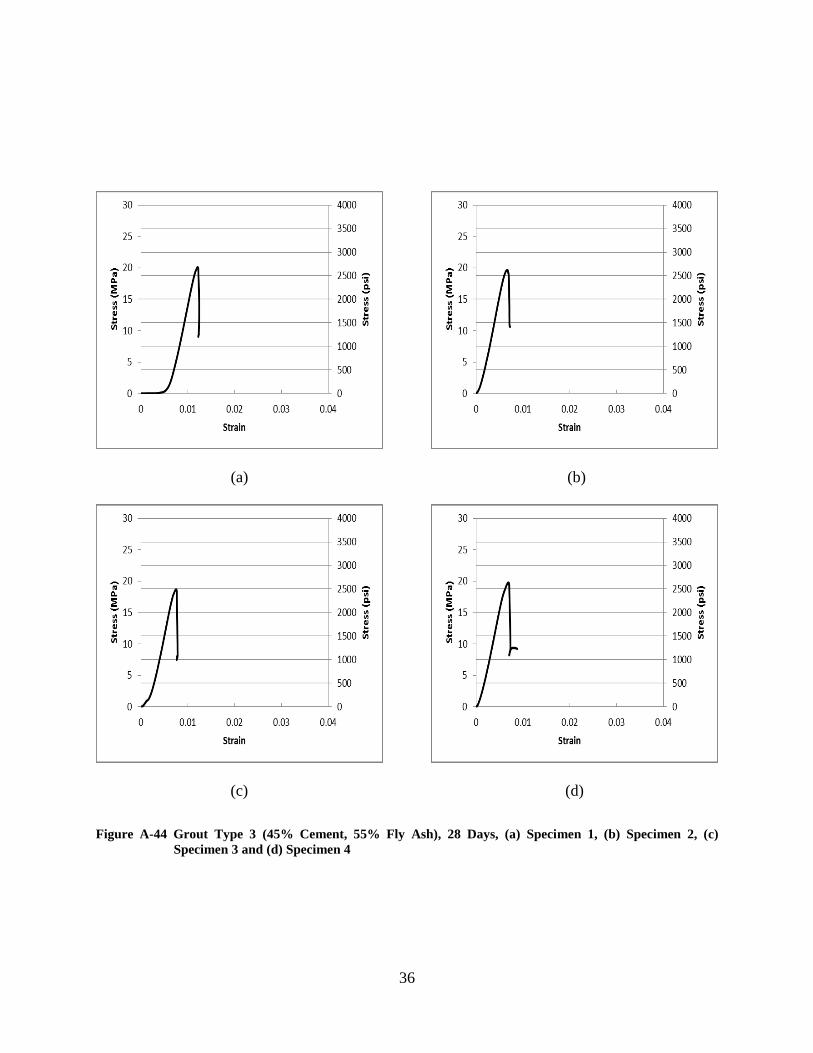
(b) Specimen 2, (c) Specimen 3 and (d) Specimen 4 .........................................................36
Figure A-13 Grout Type 3 (45% Cement, 55% Fly Ash), 42 Days, (a) Specimen 1,
(b) Specimen 2, and (c) Specimen 3 .................................................................................37
Figure A-14 Grout Type 3 (45% Cement, 55% Fly Ash), 56 Days, (a) Specimen 1,
(b) Specimen 2, (c) Specimen 3 and (d) Specimen 4 .........................................................38
Figure A-15 Grout Type 3 (45% Cement, 55% Fly Ash), 90 Days, (a) Specimen 1,
(b) Specimen 2, (c) Specimen 3 and (d) Specimen 4 .........................................................39
Figure A-16 Grout Type 4 (35% Cement, 65% Fly Ash), 14 Days, (a) Specimen 1,
(b) Specimen 2, and (c) Specimen 3 .................................................................................40
Figure A-17 Grout Type 4 (35% Cement, 65% Fly Ash), 28 Days, (a) Specimen 1,
(b) Specimen 2, (c) Specimen 3 and (d) Specimen 4 .........................................................41
Figure A-18 Grout Type 4 (35% Cement, 65% Fly Ash), 42 Days, (a) Specimen 1,
(b) Specimen 2, (c) Specimen 3 and (d) Specimen 4 .........................................................42
Figure A-19 Grout Type 4 (35% Cement, 65% Fly Ash), 56 Days, (a) Specimen 1,
(b) Specimen 2, (c) Specimen 3 and (d) Specimen 4 .........................................................43
Figure A-20 Grout Type 4 (35% Cement, 65% Fly Ash), 90 Days (a) Specimen 1,
and (b) Specimen 2 ............................................................................................................44
Figure A-21 Grout Type 5 (35% Cement, 25% Fly Ash, 40% GGBS Slag), 14 Days
(a) Specimen 1, (b) Specimen 2, and (c) Specimen 3 ........................................................45
Figure A-22 Grout Type 5 (35% Cement, 25% Fly Ash, 40% GGBF Slag), 28 Days
(a) Specimen 1, (b) Specimen 2, (c) Specimen 3 and (d) Specimen 4 ..............................46
Figure A-23 Grout Type 5 (35% Cement, 25% Fly Ash, 40% GGBF Slag), 56 Days
(a) Specimen 1, (b) Specimen 2, (c) Specimen 3 and (d) Specimen 4 ..............................47

xi
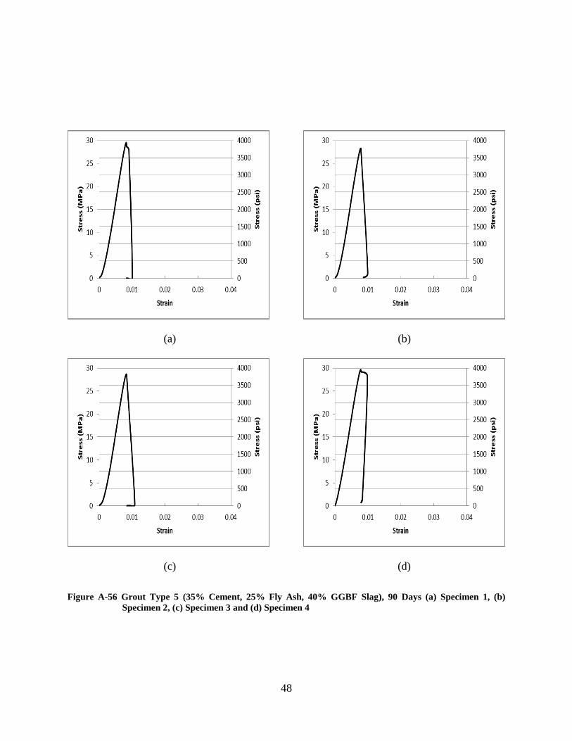
Figure A-24 Grout Type 5 (35% Cement, 25% Fly Ash, 40% GGBF Slag), 90 Days
(a) Specimen 1, (b) Specimen 2, (c) Specimen 3 and (d) Specimen 4 ..............................48
Figure A-25 Grout Type 6 (25% Cement, 25% Fly Ash, 50% GGBF Slag), 14 Days
(a) Specimen 1, and (b) Specimen 2 ..................................................................................49
Figure A-26 Grout Type 6 (25% Cement, 25% Fly Ash, 50% GGBF Slag), 28 Days
(a) Specimen 1, (b) Specimen 2, (c) Specimen 3 and (d) Specimen 4 ..............................50
Figure A-27 Grout Type 6 (25% Cement, 25% Fly Ash, 50% GGBF Slag), 56 Days
(a) Specimen 1, (b) Specimen 2, (c) Specimen 3 and (d) Specimen 4 ..............................51
Figure A-28 Grout Type 6 (25% Cement, 25% Fly Ash, 50% GGBF Slag), 90 Days
(a) Specimen 1, (b) Specimen 2, (c) Specimen 3 and (d) Specimen 4 ..............................52
Figure A-29 Grout Type 7 (15% Cement, 25% Fly Ash, 60% GGBF Slag), 14 Days
(a) Specimen 1, (b) Specimen 2, (c) Specimen 3 and (d) Specimen 4 ..............................53
Figure A-30 Grout Type 7 (15% Cement, 25% Fly Ash, 60% GGBF Slag), 28 Days
(a) Specimen 1, (b) Specimen 2, (c) Specimen 3 and (d) Specimen 4 ..............................54
Figure A-31 Grout Type 7 (15% Cement, 25% Fly Ash, 60% GGBF Slag), 56 Days
(a) Specimen 1, (b) Specimen 2, (c) Specimen 3 and (d) Specimen 4 ..............................55
Figure A-32 Grout Type 7 (15% Cement, 25% Fly Ash, 60% GGBF Slag), 90 Days
(a) Specimen 1, (b) Specimen 2, (c) Specimen 3 and (d) Specimen 4 ..............................56


1
1 INTRODUCTION
With the increasing need to minimize costs in construction, masonry has become a
material of choice for many contractors. Masonry design involves reinforcing it with steel bars
and grout, which appears like concrete and uses pea-sized gravel as coarse aggregate. Masonry
design also allows the cement within the grout to be replaced by other cementitious materials in
order to reduce material costs. This research analyzed the compressive strength of grout where
cement was replaced by different levels of fly ash and ground granulated blast-furnace (GGBF)
slag. These grout mixtures were poured into the concrete masonry prisms built with mortar type
S and tested for their compressive strength. The compressive strength at 28 days for grout must
be above 2.0 ksi, or 2000 pounds per square inch (psi) (ACI/ASCE/TMS 2008).
1.1 Objectives
The major objective of the study was to determine the viability of replacing Portland
cement in masonry grout with alternative high volume recycled cementitious materials,
consisting of fly ash and ground-granulated blast-furnace slag. Another objective of this
research was to determine whether or not grout would behave the same way when tested inside
the masonry prisms. Although there are other factors that could affect this behavior, such as the
different moduli of elasticity of the grout and the concrete masonry units, the compressive
strength was the only comparative indicator tested in this study.

2
1.2 Organization of the Report
This report consists of seven chapters. Chapter 1 presented the background and the
objectives of the study. Chapter 2 details the properties GGBF slag and fly ash, the two
materials that replaced cement in the grout mixes. Chapter 3 describes the methodology applied
to this study, as well as previous results of a similar test for grout (Siggard 2010). Chapters 4
and 5 explain the procedure taken to cast and test the prisms, including the standards that guided
the test procedures. Chapter 6 discusses the results of the compressive strength tests followed by
chapter 7 which summarizes major findings of the test.

3
2 LITERATURE REVIEW
It is imperative to know the properties of the two materials that are being introduced in
this research: GGBF slag and fly ash in order to determine if the results are actually viable.
2.1 GGBF Slag
GGBF is a by-product of iron production. The blast furnace is continuously charged
from the top with iron oxide (ore, pellets, sinter, etc.), fluxing stone (limestone and dolomite),
and fuel (coke). Two products are obtained from the furnace: molten iron that collects in the
bottom of the furnace (hearth) and liquid iron blast-furnace slag floating on the pool of iron.
Both are periodically tapped from the furnace at a temperature of about 1500 C (Langton 1989,
Spence et al. 1989).
Among the advantages of using GGBF slag in a cement mixture are the improved
workability and placeability of fresh concrete, reduced bleeding (this raises the risk of premature
finishing of concrete slabs unless allowed by the contractor), extended setting time of concrete,
reduced early age strength, reduced concrete permeability with corresponding improvement in
durability, increased sulfate resistance and reduced expansion damage from alkali-silica
reactions with aggregates (ACI Committee 2000).

4
2.2 Fly Ash
Fly ash is a fine, glass-like powder recovered from gases created by coal-fired electric
power generation. U.S. power plants produce millions of tons of fly ash annually, which is
usually dumped in landfills. Fly ash is an inexpensive replacement for Portland cement used in
concrete. Class F fly ash, with particles covered in a kind of melted glass, greatly reduces the
risk of expansion due to sulfate attack, as may occur in fertilized soils or near coastal areas. Fly
ash is produced from eastern coal (NAHB Research Center 2001).
Fly ash concrete was first used in the U.S. in 1929 for the Hoover Dam, where engineers
found that it allowed for less total cement, yet producing required strength. It is now used across
the country. Consisting mostly of silica, alumina and iron, fly ash is a pozzolana substance
containing aluminous and siliceous material that forms cement in the presence of water. When
mixed with lime and water it forms a compound similar to Portland cement. The spherical shape
of the particles reduces internal friction thereby increasing the concrete's consistency and
mobility, permitting longer pumping distances (NAHB Research Center 2001).
2.3 Chapter Summary
This chapter briefly introduced the production, chemical components, and use in concrete
making of GGBF and fly ash. These by-products of other activities have been used as
replacement materials for concrete production. The combination of GGBF slag, fly ash, and
Portland cement has proven to be an appropriate binding material for use in construction.
5
3 METHODOLOGY
Two 8” by 8” concrete masonry units (CMUs) were cast, bonding one on top of the other
using mortar type S and filling them with the designed grout type (refer to chapter 4 for details).
Tests were conducted 14 days after prisms were casted, as well as at 28, 42 and 56 days. A final
fifth test was made at 90 days, to broaden comparison standards. Seven different grout mixes
were used, and they are discussed in chapter 4 in detail. Four samples of each grout mix were
aimed to be tested in each of the five ages to obtain a more statistically accurate compressive
strength values. Additionally, hollow masonry prisms and hollow masonry units were tested as
well, along with the mortar itself.
This study was carried out in the structural laboratory of the Civil Engineering
Department of Brigham Young University, Provo, Utah, where testing of prisms with mortar
types N and M was simultaneously conducted under the same circumstances, using ASTM C-
140 test methods.
The procedure for testing was based on the procedure used for a previous project
performed by the Concrete Masonry Association of California and Nevada (Siggard 2010), the
results of which are shown in Table 3-1. As can be noted, all grout types met the 2.0 ksi at 28
days criterion, except for the one where fly ash replaced cement by 60%. Lightly shaded values
showed strength lower than 2.0 ksi.

6
Table 3-1 Grout Compressive Strength (in ksi)
Age
(days)
100%
Port-
land
cement
80%
cement
20%
fly ash
70%
cement
30%
fly ash
60%
cement
40%
fly ash
50%
cement
50%
fly ash
40%
cement
60%
fly ash
50%
cement
50%
fly ash
& slag
40%
cement
60%
fly ash
& slag
30%
cement
70%
fly ash
& slag
20%
cement
80%
fly ash
& slag
7 2.98 2.78 2.45 1.54 1.61 0.91 1.89 2.26 1.94 1.46
14 3.28 2.92 2.97 2.14 2.09 1.15 2.89 3.27 2.77 1.94
28 4.06 3.31 3.83 2.69 2.88 1.44 3.31 3.23 3.41 2.43
42 4.17 3.81 3.88 3.05 3.13 1.93 3.66 4.54 4.21 2.71
56 4.31 4.25 4.65 3.33 2.96 2.07 5.01 4.83 4.26 3.14
180 4.12 5.18 5.67 4.69 4.33 3.79 6.21 6.01 5.26 3.39

7
4 CASTING OF PRISMS
A masonry prism is an assemblage of masonry units and mortar that is constructed to
serve as a test specimen for determining properties of masonry assemblages. In this research,
prisms were constructed by assembling two concrete masonry units, one on top of the other,
using mortar as the bonding material in the contact surface of the masonry units, not inside (see
Figures 4-1 and 4-2). This chapter discusses the materials used and the grout composition in
detail.
Figure 4-1 Full Mortar Beds
Figure 4-2 Placing of Top Unit on Mortar
4.1 Materials
The materials included CMUs, Portland cement, sand, pea gravel, class-F fly ash, GGBF
slag, and mortar type S and gypsum cement.

8
The sand and pea gravel served as the aggregate utilized for all grout mixes. The cement,
fly ash and slag were used as the cementitious material in the grout, using varied mixture
percentages according to the design of the experiment set up for the study. The gypsum cement
served as the capping agent, using ASTM standards as a guideline for the procedure (ASTM C-
1552 2010). A 1/8” thick, 10” x 10” glass plates (see Figure 4-3) were used to equally distribute
the gypsum on the rough surface of the prism. Oil was necessary to prevent the capping from
sticking to the glass, hence WD-40 spray oil was used for this study (see Figure 4-4). Plastic
bags were used to seal the prisms and let the mortar cure under the same humidity right after
casting. The plastic bags were reopened the following day to fill the prisms with the
corresponding grout, and then resealed to provide the same conditions for the curing of the grout.
Figure 4-3 Glass Plate (1/8" thick, 10"x10")
Figure 4-4 WD-40 Spray Oil
As shown in the next section, there are seven different grout compositions. Five prisms
were cast in order to be able to test four of them and have an extra specimen in case one had a
bad break. The total amount of prisms, considering the five age groups, the five specimens per
grout type, and the seven grout types plus the hollow prisms, added up to 200 prisms. In total,
400 CMUs were required for the casting of all 200 prisms.

9
In order to calculate the total amount of grout, the volume of the void created by the
bonding of two CMUs together needed to be determined. For 200 prisms, 2 cubic yards (54
cubic feet) of grout would be needed. Nevertheless, this number was multiplied by a factor of
two due to the densification of the mix, which increased the volume of grout needed to 4 cubic
yards – twice as much of the calculated amount for all testing. With this number as a guide,
different percentages were assigned for each component in the grout mix, which resembled those
obtained by the Concrete Masonry Association of California and Nevada: 5.75% for cement,
3.75% for fly ash, 7.50% for slag, 50% for sand, and 33% for gravel (Siggard, 2010). A 10%
increase was finally added to compensate any unforeseen events, and thus a cubic footage was
obtained for each of them. The final quantities ordered are shown in Table 4-1.
Table 4-1 Quantities Ordered for Each Material
Constituent
Volume
(yd3)
10% volume
increase (yd3)
Amount to
order (yd3)
Cement 0.23 0.25 0.33
Fly Ash 0.15 0.16 0.17
Slag 0.30 0.33 0.33
Sand 2.00 2.20 2.33
Gravel 1.32 1.45 1.50
4.2 Grout Composition
Seven grout mix types with varying cementitious materials were used in the prisms.
These cementitious materials included cement, GGBF slag, and class-F fly ash. It was
imperative that the prisms were labeled to identify them with particular grout mix types. Hence,
a system with seven different colored spray paints was used. Table 4-2 in the next page shows
the percent weight of cementitious material in each of the seven grout types. The first mix type,

10
labeled as “0” in Table 4-2, had no cementitious materials because these prisms were hollow –
the voids were not filled with grout.
Table 4-2 Percentages of Cementitious Materials in the Eight Different Grout Mix Types
Grout mix type Portland cement Fly Ash GGBF Slag Color key
0 0% 0% 0% ---
1 100% 0% 0% Orange
2 55% 45% 0% White
3 45% 55% 0% Red
4 35% 65% 0% Blue
5 35% 25% 40% Green
6 25% 25% 50% Pink
7 15% 25% 60% Yellow
On April 6th
2011, prisms casting commenced, using the seven different mix types,
whose grout compositions in pounds are found in Table 4-3.
Table 4-3 Amount of Each Material for the Different Grout Compositions (in lbs.)
Grout Mix
Type Sand Gravel Water Cement Fly Ash Slag W/C Ratio
1 1923.5 813.8 566.9 591.8 ___ ___ 0.8832
2 1923.5 813.8 566.9 325.5 266.3 ___ 0.8832
3 1442.6 610.3 425.2 199.7 244.1 ___ 0.8832
4 1346.4 569.6 396.8 145.0 269.3 __ 0.8832
5 1346.4 569.6 396.8 145.0 103.6 165.7 0.8832
6 1413.8 598.1 373.8 108.8 108.8 217.5 0.7846
7 1413.8 598.1 373.8 65.3 108.8 261.0 0.7846
An important step during the prism production was to let the grout cure within the prisms
at a constant humidity. This requirement was met by placing the prisms in plastic bags as shown
in Figure 4-5. A plastic bag was placed under each prism prior to the production to facilitate
easy rolling-up and sealing tasks. With the assistance of professional masons and their crews, all

11
prisms were assembled using mortar. The first four mix types were prepared and grout was
poured the following day (see Figure 4-6).
Figure 4-5 Bagged Prisms
Figure 4-6 Grout Type 4 Being Poured
The remaining grout types (5, 6 and 7) were prepared and poured two days later on April
8th
2011, filling the rest of the prisms that had already been prepared. Test dates were set
following the same curing pattern used by the Concrete and Masonry Association of California
and Nevada, as shown in Table 4-4.
Table 4-4 Scheduled Dates for Prisms Testing During Year 2011
Age 14 days 28 days 42 days 56 days 90 days
Date Apr 22-23 May 5-6 May 19-20 Jun 2-3 Jul 7-8
On April 22nd
and 23rd
2011, the first compressing testing was done using the universal
machine available in the Structures Laboratory in the Ira Fulton College of Engineering &
Technology at Brigham Young University as shown in Figure 4-7. In order to comply with
ASTM C-140 standards, two plates were added to the compressing machine both on the top and
12
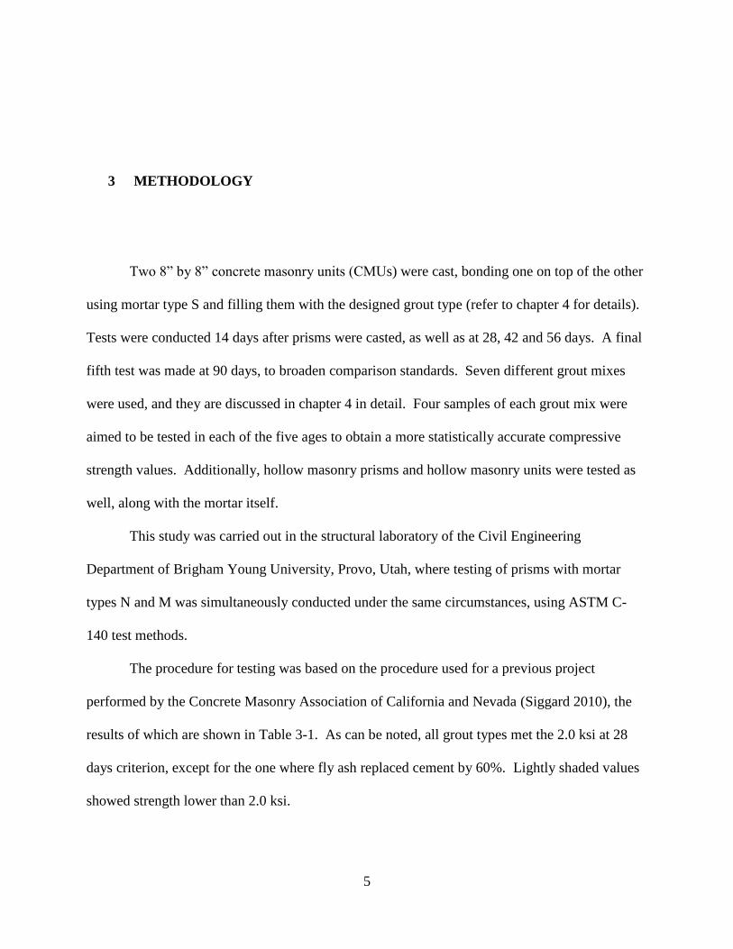
the bottom. The ASTM C-140 standard states that the sides of the bearing plates must surpass
the face of the prism by one bearing-plate thickness.
Figure 4-7 Prism Filled with Grout Type 1 Being Tested
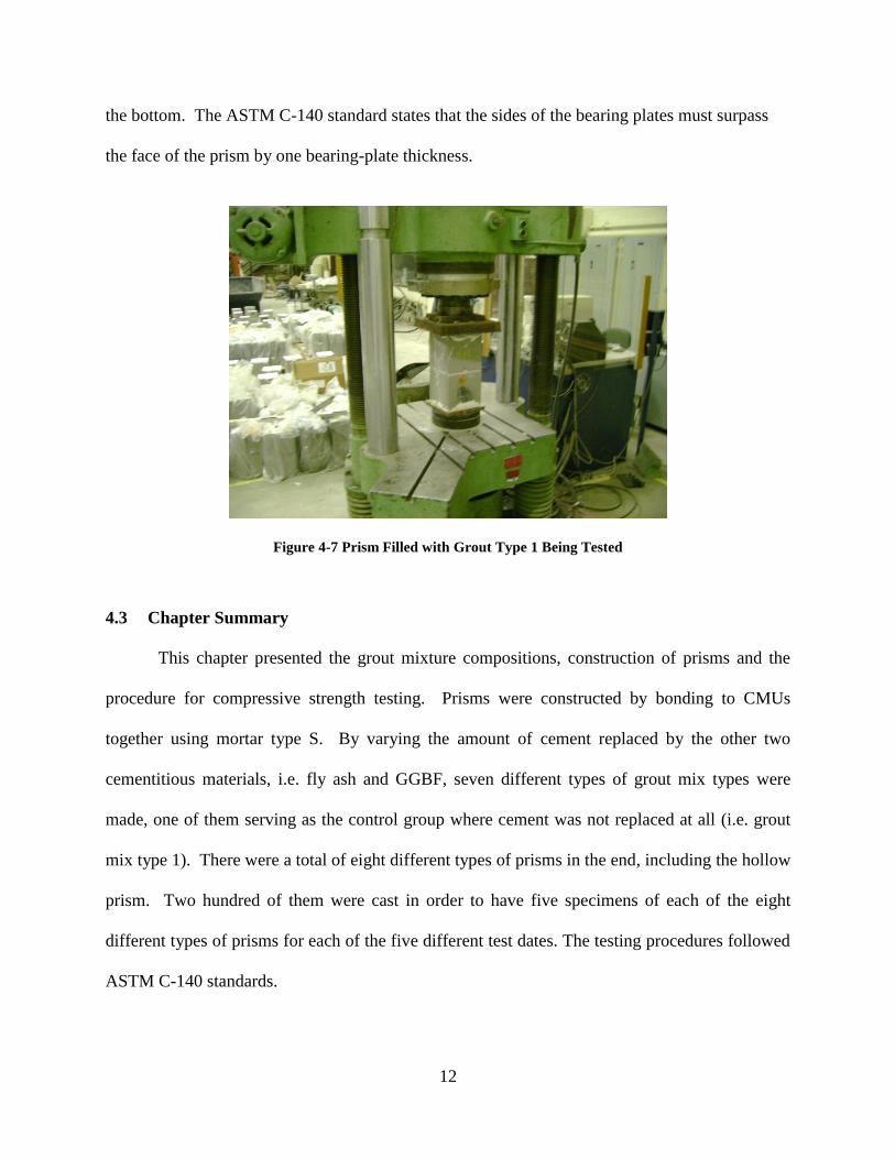
4.3 Chapter Summary
This chapter presented the grout mixture compositions, construction of prisms and the
procedure for compressive strength testing. Prisms were constructed by bonding to CMUs
together using mortar type S. By varying the amount of cement replaced by the other two
cementitious materials, i.e. fly ash and GGBF, seven different types of grout mix types were
made, one of them serving as the control group where cement was not replaced at all (i.e. grout
mix type 1). There were a total of eight different types of prisms in the end, including the hollow
prism. Two hundred of them were cast in order to have five specimens of each of the eight
different types of prisms for each of the five different test dates. The testing procedures followed
ASTM C-140 standards.

13
5 TESTING
Prior to carrying out the tests, the specimens needed to be prepared. Preparation of the
specimens for testing at the specified date involved pulling the specimens out of the bundle and
laying them out on the floor, debagging them, and capping them. After each testing day, data
were recorded and stored and the debris properly disposed of. This chapter discusses the prism
labeling scheme and the capping procedures used in this study.
5.1 Labeling
In order to keep track of all the different grout types, color spray was used to label the
prisms, a process which did not affect any of the structural or chemical properties of the mortar,
grout, or the masonry units. Table 5-1 shows the color assignment to different grout types.
Table 5-1 Color Key Used to Identify Grout Types
No. GROUT TYPE COLOR
1 100% cement Orange
2 55% cement, 45% fly ash White
3 45% cement, 55% fly ash Red
4 35% cement, 65% fly ash Blue
5 35 % cement, 25% fly ash, 40% slag Green
6 25% cement, 25% fly ash, 50% slag Pink
7 15% cement, 25% fly ash, 60% slag Yellow
14
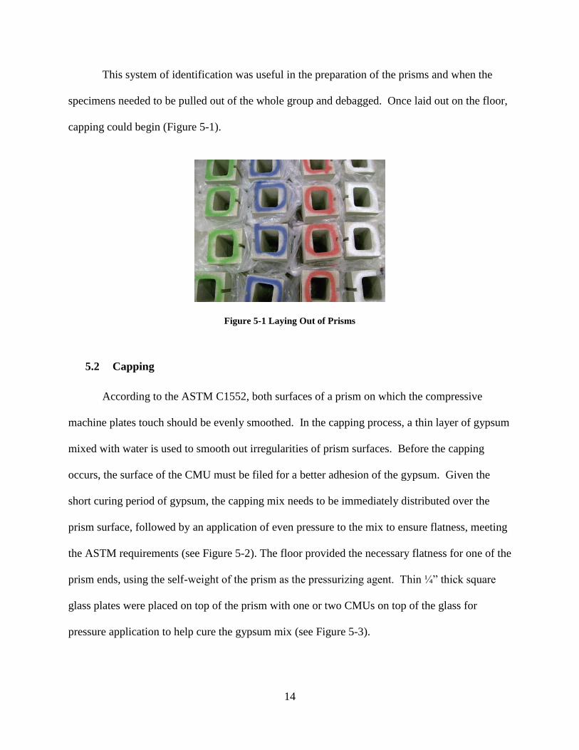
This system of identification was useful in the preparation of the prisms and when the
specimens needed to be pulled out of the whole group and debagged. Once laid out on the floor,
capping could begin (Figure 5-1).
Figure 5-1 Laying Out of Prisms
5.2 Capping
According to the ASTM C1552, both surfaces of a prism on which the compressive
machine plates touch should be evenly smoothed. In the capping process, a thin layer of gypsum
mixed with water is used to smooth out irregularities of prism surfaces. Before the capping
occurs, the surface of the CMU must be filed for a better adhesion of the gypsum. Given the
short curing period of gypsum, the capping mix needs to be immediately distributed over the
prism surface, followed by an application of even pressure to the mix to ensure flatness, meeting
the ASTM requirements (see Figure 5-2). The floor provided the necessary flatness for one of the
prism ends, using the self-weight of the prism as the pressurizing agent. Thin ¼” thick square
glass plates were placed on top of the prism with one or two CMUs on top of the glass for
pressure application to help cure the gypsum mix (see Figure 5-3).

15
Figure 5-2 Gypsum Cement Mixed with Water
Figure 5-3 Capped Prisms
To prevent the gypsum mix from adhering to the glass plates, WD-40 oil (see Figure 4-4)
was sprayed on each side of the glass plates before their use, allowing a smooth separation
between the gypsum mix and the glass plates.
5.3 Chapter Summary
A color code was used to identify the prisms which were to be filled with each of the
grout types, including the hollow specimens. Once the prisms had cured, they were stored until
the next testing date, where the corresponding specimens would be selected out of the whole
bundle, debagged, and then capped according to ASTM C1552 standards.
It is important to note that besides the prisms with the seven different types of grout mix,
three other types of specimens were tested: hollow prisms, CMUs (see Figure 5-4), and mortar
cubes (see Figure 5-5). By testing these other specimens, their contribution to the overall
compressive strength of the masonry prisms can be observed.

16
Figure 5-4 Concrete Masonry Units (CMUs)
Figure 5-5 Mortar Cubes

17
6 TEST RESULTS
This chapter presents the results of the compressive strength test of masonry prisms and
their corresponding graphical representations, including a discussion and analysis thereof.
6.1 Compressive Strengths by Test Date
Three prisms at 14 days and four prisms at every other time were tested and the results of
the compressive strength tests are shown on Table 6-1.
Table 6-1 Raw Compressive Strengths (in psi) of Prisms by Grout Type
1 2 3 4 1 2 3 4 1 2 3 4 1 2 3 4
14 2976 3423 3216 2580 2597 2546 1617 2098 2047 1686 1875 1686
28 3148 3113 2941 3234 2494 2718 2494 2546 2133 1806 1909 1875 1668 2133 2030 1995
42 2855 3406 2993 3836 2030 3096 3182 3148 2683 2614 2494 2632 2425 2477 2580 2563
56 3732 3887 3320 3148 3406 3457 3457 3320 3079 2528 2528 3079 2374 2632 2580 1944
90 4042 2855 3990 3698 3474 3801 3612 3096 2993 2855 3148 3234 3044 3062 3113 3130
1 (100% cement) 2 (45% fly ash) 3 (55% fly ash) 4 (65% fly ash)
GROUT TYPEDAYS
1 2 3 4 1 2 3 4 1 2 3 4
14 2872 2546 2855 2890 2511 2339 2924 2305 2460
28 2666 2821 3027 2976 2666 2769 2322 2924 2253 2356 2374 2752
42 3595 3612 3732 3199 3646 3698 3388 3423 3113 3320 3130 3062
56 3715 3062 3732 3595 3784 3457 4197 3698 3474 3130 3474 3543
90 3939 3767 3818 3956 3698 4317 3629 2872 3474 3388 3406 3199
GROUT TYPEDAYS 5 (25% fly ash, 40% 6 (25% fly ash, 50% 7 (25% fly ash, 60%

18
The results in each grout type were averaged, ruling out those values beyond one
standard deviation, and the final values are shown in Table 6-2. All stress – strain curves
resulted from the compressive strength test are included in Appendix A.
Table 6-2 Average Compressive Strengths (in psi) of Prisms by Grout Type
1 2 3 4 5 6 7
14 3217 2589 2067 1684 2865 2959 2375
28 3131 2514 1888 2012 2901 2716 2329
42 3205 3117 2630 2516 3650 3536 3085
56 3520 3441 2803 2526 3674 3741 3497
90 3910 3547 3070 3058 3741 3668 3399
DAYSGROUT TYPE
6.2 Graphical Presentation of Changes in Compressive Strengths
The results from Table 6-2 are graphed in Figure 6-1to evaluate the trends.
Figure 6-1 Compressive Strengths Curves

19
Grout type 1 (100% Portland cement), which is the control group, was graphed using a
thicker, continuous dark line. Grout types 2, 3 and 4 (fly ash replacement of 45%, 55% and 65%
respectively) were graphed using dotted lines. Grout types 5, 6 and 7 (GGBF slag replacement
of 40%, 50% and 60% respectively, with a fixed fly ash replacement of 25%) were graphed
using dashed lines. All grout types displayed a compressive strength of over 2000 psi since the
first test day (14 days of age), except for grout type 4 (35% cement and 65% fly ash). At any
point, the strength of any of the grout types tends to increase. The curves in Figure 6-1 (previous
page) show this trend, except for the point at 28 days into curing, where it decreases. The grout
types seem to have weakened at this time, and that is not counter intuitive. It is difficult to
determine what went wrong, but from the different scenarios that could contribute to the results,
it is suspected that some steps of the prism preparation contributed to this anomaly. Figure 6-2
shows the same information as Figure 6-1, without the compressive strengths from day 28.
Figure 6-2 Compressive Strength Curves with 28-Day Strength Data Removed

20
Grout type 1 (100% Portland cement) possesses an initial compressive strength between
3000 and 3500 psi on the first three testing dates, and then increases to 4000 psi at 90 days. The
next three grout types 2, 3, and 4, where Portland cement was replaced by fly ash in the amounts
of 45%, 55%, and 65% respectively, decreased gradually in compressive strength up to a point
where grout type 4 is not adequate anymore, since it is not until after 28 days that it reaches 2000
psi.
The last 3 grout types, numbers 5, 6, and 7, where fly ash replacement stayed fixed at
25%, while GGBF slag replacement was modified by 40%, 50% and 60% respectively,
experienced a boost in compressive strength back to a point where grout type 5 showed similar
strength than that of number 1, the control group.
Again, just like it happened with grout types 2, 3 and 4, types 6 and 7 decreased
gradually, with the difference that grout type 7 still remained adequate, given its high
compressive strength at 14 days (around 2400 psi).
6.3 Chapter Summary
This chapter showed the results of the compressive strength tests, both numerically and
graphically. The average values obtained for each grout type in each testing day were plotted and
the corresponding curves obtained. A discrepancy was observed during the 28-day break, which
was explained. It was noted that as fly ash replacement increased, the compressive strength of
prisms decreased, and the same behavior occurred with GGBF slag, but at a slower rate.

21
7 CONCLUSION
This research was conducted to determine the viability of replacing Portland cement in
masonry grout with fly ash and GGBF slag. After performing the corresponding compressive
strength tests, the prisms resisted loads over 2000 psi (the minimum set by the ACI), especially
those built with GGBF slag. Portland cement content can be as little as 15% in volume in the
mix as a cementitious material, replacing the rest with 60% of GGBF slag and 25% of fly ash.
The compressive strengths of grout itself and those of grout within the prisms were
finally compared as shown in Table 7-1. Grout mix types 1 and 5, which were the grout mix
types with higher compressive strengths when grout was only tested by itself, showed to be
weaker when tested within a prism. On the other hand, type 7, the grout mix type with the
highest replacement (25% fly ash and 60% GGBF slag), showed a tendency to be stronger when
tested within a prism than when tested by itself.
Table 7-1 Comparison of Compressive Strengths (in kips) Between Grout and Prism
grout prism grout prism grout prism grout prism grout prism grout prism grout prism
14 3.28 3.22 2.14 2.59 2.09 2.07 1.15 1.68 3.27 2.86 2.77 2.96 1.94 2.37
28 4.06 3.13 2.69 2.51 2.88 1.89 1.44 2.01 3.23 2.90 3.41 2.72 2.43 2.33
42 4.17 3.20 3.05 3.12 3.13 2.63 1.93 2.52 4.54 3.65 4.21 3.54 2.71 3.08
56 4.3 3.52 3.33 3.44 2.96 2.80 2.07 2.53 4.83 3.67 4.26 3.74 3.14 3.50
90 -- 3.91 -- 3.55 -- 3.07 -- 3.06 -- 3.88 -- 3.67 -- 3.40
180 4.12 -- 4.69 -- 4.33 -- 3.79 -- 6.01 -- 5.26 -- 3.59 --
7 (25% fly
ash, 60% Age
(days)
6 (25% fly
ash, 50%
1 (100%
cement)
2 (45%
fly ash)
3 (55%
fly ash)
4 (65%
fly ash)
5 (25% fly
ash, 40%


23
REFERENCES
ACI Committee 233. “Ground Granulated Blast-Furnace Slag as a Cementitious Constituent in
Concrete”, http:// www.bpesol.com/bachphuong/media/images/book/233r_95.pdf.
Accessed on December 2011.
American Concrete Institute (ACI), American Society of Civil Engineers (ASCE), and The
Masonry Society (TMS), ACI 530-08 - Building Code Requirements & Specification for
Masonry Structures, 2008
American Society for Testing and Materials. Standard Test Methods for Sampling and Testing
Concrete Masonry Units and Related Units (ASTM C-140), 2010 edition.
American Society for Testing and Materials. Standard Practice for Capping Concrete Masonry
Unites, Related Units and Masonry Prisms for Compression Testing, (ASTM C-1552)
2010.
NAHB Research Center. “Fly Ash Concrete, Inexpensive Replacement for Portland Cement”, at
http://www.toolbase.org/Technology-Inventory/Foundations/fly-ash-concrete. Accessed
December 2011
Siggard, Kurt. Testing for Analysis of High Replacement Fly Ash and Ground Granulated Blast
Furnace Slag in Masonry Grout 2010.


25
APPENDIX A. EXAMPLES OF STRESS–STRAIN CURVES OF TESTED PRISMS
(a)
(b)
Figure A-33 Grout Type 1 (100% Cement), 14 Days (a) Specimen 1 and (b) Specimen 2

26
(a)
(b)
(c)
(d)
Figure A-34 Grout Type 1 (100% Cement), 28 Days (a) Specimen 1, (b) Specimen 2, (c) Specimen 3 and (d)
Specimen 4

27
(a)
(c)
(b)
(d)
Figure A-35 Grout Type 1 (100% Cement), 42 Days (a) Specimen 1, (b) Specimen 2, (c) Specimen 3 and (d)
Specimen 4

28
(a)
(c)
(b)
(d)
Figure A-36 Grout Type 1 (100% Cement), 56 Days (a) Specimen 1, (b) Specimen 2, (c) Specimen 3 and (d)
Specimen 4

29
(a)
(c)
(b)
(d)
Figure A-37 Grout Type 1 (100% Cement), 90 Days (a) Specimen 1, (b) Specimen 2, (c) Specimen 3 and (d)
Specimen 4

30
(a)
(c)
(b)
Figure A-38 Grout Type 2 (55% Cement, 45% Fly Ash), 14 Days, (a) Specimen 1, (b) Specimen 2, and (c)
Specimen 3

31
(a)
(c)
(b)
(d)
Figure A-39 Grout Type 2 (55% Cement, 45% Fly Ash), 28 Days, (a) Specimen 1, (b) Specimen 2, (c)
Specimen 3 and (d) Specimen 4

32
(a)
(c)
(b)
(d)
Figure A-40 Grout Type 2 (55% Cement, 45% Fly Ash), 42 Days, (a) Specimen 1, (b) Specimen 2, (c)
Specimen 3 and (d) Specimen 4

33
(a)
(c)
(b)
(d)
Figure A-41 Grout Type 2 (55% Cement, 45% Fly Ash), 56 Days, (a) Specimen 1, (b) Specimen 2, (c)
Specimen 3 and (d) Specimen 4

34
(a)
(c)
(b)
(d)
Figure A-42 Grout Type 2 (55% Cement, 45% Fly Ash), 90 Days, (a) Specimen 1, (b) Specimen 2, (c)
Specimen 3 and (d) Specimen 4

35
(a)
(c)
(b)
Figure A-43 Grout Type 3 (45% Cement, 55% Fly Ash), 14 Days, (a) Specimen 1, (b) Specimen 2, and (c)
Specimen 3
36
(a)
(c)
(b)
(d)
Figure A-44 Grout Type 3 (45% Cement, 55% Fly Ash), 28 Days, (a) Specimen 1, (b) Specimen 2, (c)
Specimen 3 and (d) Specimen 4

37
(a)
(c)
(b)
Figure A-45 Grout Type 3 (45% Cement, 55% Fly Ash), 42 Days, (a) Specimen 1, (b) Specimen 2, and (c)
Specimen 3

38
(a)
(c)
(b)
(d)
Figure A-46 Grout Type 3 (45% Cement, 55% Fly Ash), 56 Days, (a) Specimen 1, (b) Specimen 2, (c)
Specimen 3 and (d) Specimen 4

39
(a)
(c)
(b)
(d)
Figure A-47 Grout Type 3 (45% Cement, 55% Fly Ash), 90 Days, (a) Specimen 1, (b) Specimen 2, (c)
Specimen 3 and (d) Specimen 4

40
(a)
(c)
(b)
Figure A-48 Grout Type 4 (35% Cement, 65% Fly Ash), 14 Days, (a) Specimen 1, (b) Specimen 2, and (c)
Specimen 3

41
(a)
(c)
(b)
(d)
Figure A-49 Grout Type 4 (35% Cement, 65% Fly Ash), 28 Days, (a) Specimen 1, (b) Specimen 2, (c)
Specimen 3 and (d) Specimen 4

42
(a)
(b)
(c) (d)
Figure A-50 Grout Type 4 (35% Cement, 65% Fly Ash), 42 Days, (a) Specimen 1, (b) Specimen 2, (c)
Specimen 3 and (d) Specimen 4

43
(a)
(b)
(c) (d)
Figure A-51 Grout Type 4 (35% Cement, 65% Fly Ash), 56 Days, (a) Specimen 1, (b) Specimen 2, (c)
Specimen 3 and (d) Specimen 4

44
(a)
(b)
Figure A-52 Grout Type 4 (35% Cement, 65% Fly Ash), 90 Days (a) Specimen 1, and (b) Specimen 2

45
(a)
(b)
(c)
Figure A-53 Grout Type 5 (35% Cement, 25% Fly Ash, 40% GGBS Slag), 14 Days (a) Specimen 1, (b)
Specimen 2, and (c) Specimen 3

46
(a)
(b)
(c) (d)
Figure A-54 Grout Type 5 (35% Cement, 25% Fly Ash, 40% GGBF Slag), 28 Days (a) Specimen 1, (b)
Specimen 2, (c) Specimen 3 and (d) Specimen 4

47
(a)
(b)
(c) (d)
Figure A-55 Grout Type 5 (35% Cement, 25% Fly Ash, 40% GGBF Slag), 56 Days (a) Specimen 1, (b)
Specimen 2, (c) Specimen 3 and (d) Specimen 4
48
(a)
(b)
(c) (d)
Figure A-56 Grout Type 5 (35% Cement, 25% Fly Ash, 40% GGBF Slag), 90 Days (a) Specimen 1, (b)
Specimen 2, (c) Specimen 3 and (d) Specimen 4

49
(a)
(b)
Figure A-57 Grout Type 6 (25% Cement, 25% Fly Ash, 50% GGBF Slag), 14 Days (a) Specimen 1, and (b)
Specimen 2

50
(a)
(b)
(c) (d)
Figure A-58 Grout Type 6 (25% Cement, 25% Fly Ash, 50% GGBF Slag), 28 Days (a) Specimen 1, (b)
Specimen 2, (c) Specimen 3 and (d) Specimen 4

51
(a)
(b)
(c) (d)
Figure A-59 Grout Type 6 (25% Cement, 25% Fly Ash, 50% GGBF Slag), 56 Days (a) Specimen 1, (b)
Specimen 2, (c) Specimen 3 and (d) Specimen 4

52
(a)
(b)
(c) (d)
Figure A-60 Grout Type 6 (25% Cement, 25% Fly Ash, 50% GGBF Slag), 90 Days (a) Specimen 1, (b)
Specimen 2, (c) Specimen 3 and (d) Specimen 4

53
(a)
(b)
(c)
Figure A-61 Grout Type 7 (15% Cement, 25% Fly Ash, 60% GGBF Slag), 14 Days (a) Specimen 1, (b)
Specimen 2, (c) Specimen 3 and (d) Specimen 4

54
(a)
(b)
(c) (d)
Figure A-62 Grout Type 7 (15% Cement, 25% Fly Ash, 60% GGBF Slag), 28 Days (a) Specimen 1, (b)
Specimen 2, (c) Specimen 3 and (d) Specimen 4

55
(a)
(b)
(c) (d)
Figure A-63 Grout Type 7 (15% Cement, 25% Fly Ash, 60% GGBF Slag), 56 Days (a) Specimen 1, (b)
Specimen 2, (c) Specimen 3 and (d) Specimen 4

56
(a)
(b)
(c) (d)
Figure A-64 Grout Type 7 (15% Cement, 25% Fly Ash, 60% GGBF Slag), 90 Days (a) Specimen 1, (b)
Specimen 2, (c) Specimen 3 and (d) Specimen 4


![INí] ) .lliTA1'HW CF THE COHPRESSlVE STRENGTH OF MASONRY PRISMS … · 2015-07-22 · INí] ") .lliTA1'HW CF THE COHPRESSlVE STRENGTH OF MASONRY PRISMS Robert G. Drys .Ja le, Prof](https://static.fdocuments.net/doc/165x107/5e5689617e07517341755cc9/in-llita1hw-cf-the-cohpresslve-strength-of-masonry-prisms-2015-07-22-in.jpg)