CHRYSLER GROUP LLC - Login Page 105...CHRYSLER GROUP LLC Chrysler Security ... construction project...
76
CHRYSLER GROUP LLC Chrysler Security Services Fire Protection Engineering Standards Standard 105 New Construction Issued: 4/88 Revised: 8/04 11/04 1/05 4/05 11/05 2/06 3/06 4/06 7/06 9/07 11/07 2/09 03/09 08/1 09/09 2/10 3/10 7/10 8/10 11/10 1/11 4/11 5/11 8/11 9/11 10/11 1/12 5/12 7/12 9/12
-
Upload
truongkhanh -
Category
Documents
-
view
225 -
download
1
Transcript of CHRYSLER GROUP LLC - Login Page 105...CHRYSLER GROUP LLC Chrysler Security ... construction project...
CHRYSLER GROUP LLC
Chrysler Security Services
Fire Protection Engineering Standards
Standard 105
New Construction
Issued: 4/88 Revised: 8/04 11/04 1/05 4/05 11/05 2/06 3/06 4/06 7/06 9/07 11/07 2/09 03/09
08/1 09/09 2/10 3/10 7/10 8/10 11/10 1/11 4/11 5/11 8/11 9/11 10/11 1/12 5/12 7/12 9/12
Standard 105 2
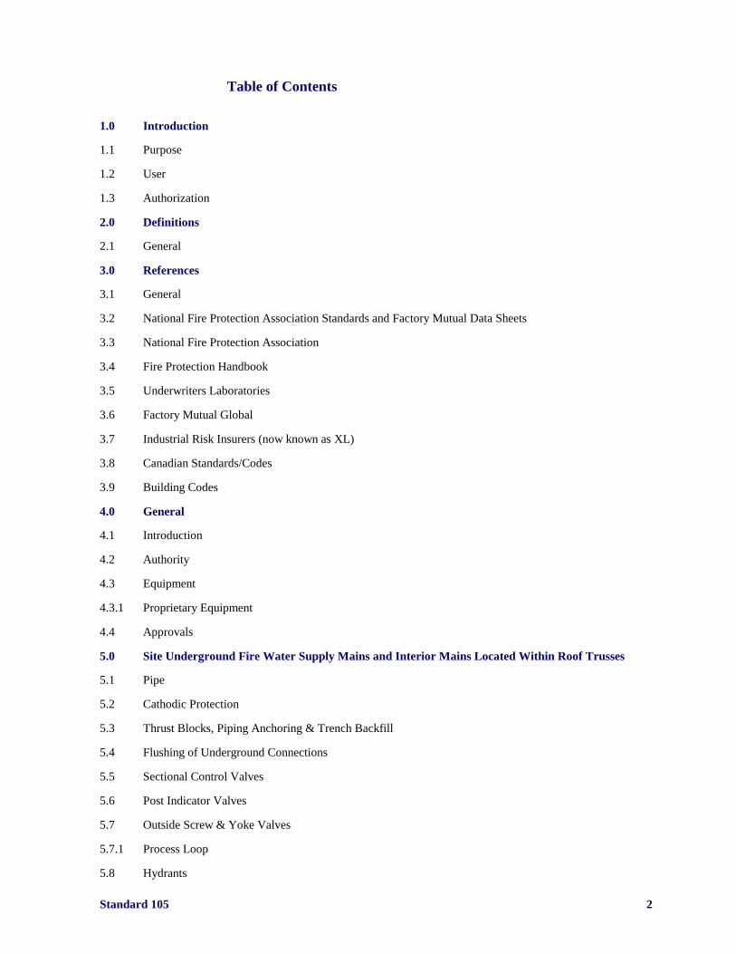
Table of Contents
1.0 Introduction
1.1 Purpose
1.2 User
1.3 Authorization
2.0 Definitions
2.1 General
3.0 References
3.1 General
3.2 National Fire Protection Association Standards and Factory Mutual Data Sheets
3.3 National Fire Protection Association
3.4 Fire Protection Handbook
3.5 Underwriters Laboratories
3.6 Factory Mutual Global
3.7 Industrial Risk Insurers (now known as XL)
3.8 Canadian Standards/Codes
3.9 Building Codes
4.0 General
4.1 Introduction
4.2 Authority
4.3 Equipment
4.3.1 Proprietary Equipment
4.4 Approvals
5.0 Site Underground Fire Water Supply Mains and Interior Mains Located Within Roof Trusses
5.1 Pipe
5.2 Cathodic Protection
5.3 Thrust Blocks, Piping Anchoring & Trench Backfill
5.4 Flushing of Underground Connections
5.5 Sectional Control Valves
5.6 Post Indicator Valves
5.7 Outside Screw & Yoke Valves
5.7.1 Process Loop
5.8 Hydrants
Standard 105 3
5.9 Fire Department Connections
5.10 Valves in Pits
5.11 Hydrostatic Tests
5.12 Backflow Prevention and Low Suctions Pressure Regulating Valves
6.0 Water Supply
6.1 Suction Supply
6.1.1 Suction Tank
6.2 Fire Pump House
6.3 Fire Pumps
6.4 Jockey (Pressure Maintenance) Pump
6.5 Fire Pumps Types and Quantity
7.0 Roof Decks
7.1 General
7.2 Roof Coverings
7.2.1 Roof Covering Classifications – Factory Mutual
7.2.2 Roof Covering Classifications - NFPA
7.3 Construction
7.4 Standing Seam Roof Systems
8.0 Fire Walls & Partitions
8.1 General
8.2 Fire Resistance
8.3 Application
8.4 Parapets
9.0 Smoke & Heat Venting
9.1 General
9.2 Vent Types
9.3 Explosion Relief Venting
9.4 Draft Curtains
10.0 Sprinkler System Requirements
10.1 Classifications of Occupancy
10.2 Design Densities
10.3 Sprinkler Heads
10.4 Special Requirements
10.4.1 Cross Ties
10.4.2 Guard Posts
Standard 105 4
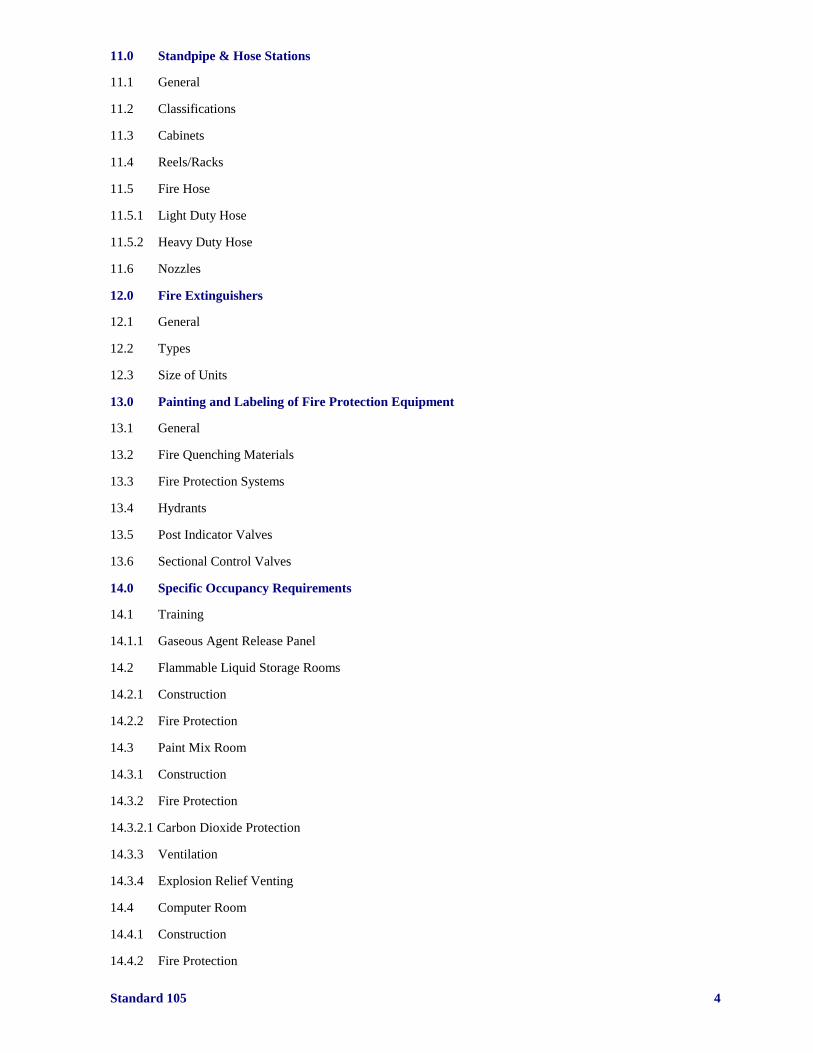
11.0 Standpipe & Hose Stations
11.1 General
11.2 Classifications
11.3 Cabinets
11.4 Reels/Racks
11.5 Fire Hose
11.5.1 Light Duty Hose
11.5.2 Heavy Duty Hose
11.6 Nozzles
12.0 Fire Extinguishers
12.1 General
12.2 Types
12.3 Size of Units
13.0 Painting and Labeling of Fire Protection Equipment
13.1 General
13.2 Fire Quenching Materials
13.3 Fire Protection Systems
13.4 Hydrants
13.5 Post Indicator Valves
13.6 Sectional Control Valves
14.0 Specific Occupancy Requirements
14.1 Training
14.1.1 Gaseous Agent Release Panel
14.2 Flammable Liquid Storage Rooms
14.2.1 Construction
14.2.2 Fire Protection
14.3 Paint Mix Room
14.3.1 Construction
14.3.2 Fire Protection
14.3.2.1 Carbon Dioxide Protection
14.3.3 Ventilation
14.3.4 Explosion Relief Venting
14.4 Computer Room
14.4.1 Construction
14.4.2 Fire Protection
Standard 105 5
14.5 Vehicle Test Room
14.5.1 Construction
14.5.2 Fire Protection
14.5.3 Explosion Relief Venting
14.6 Engine Test Cell Room
14.6.1 Construction
14.6.2 Fire Protection
14.6.3 Explosion Relief Venting
14.6.4 Dyno in a Box
14.6.4.1 Construction
14.6.4.2 Fire Protection
14.6.4.3 Explosion Relief Venting
14.7 Gasoline Fill Operations
14.7.1 Fire Protection
14.8 Manned Pits
15.0 Support Areas
15.1 Solvent Tank Farm
15.2 Exterior Electrical Substations
15.2.1 Interior Electrical Substations
15.3 Power House
16.0 Fire Alarm Systems/Fire Release Panels
16.1 System Types
16.1.1 Local System
16.1.2 Auxiliary Systems
16.1.3 Remote (Central) Station Systems
16.1.4 Proprietary Systems
16.2 Points to Alarm
16.3 Evacuation Systems
16.4 Fire Release Panels
16.5 Proprietary Products
17.0 Interlocks
17.1 Flammable Liquid Storage Room
17.2 Paint Mix Room
17.3 Paint Spray Booth
17.4 Computer Room
Standard 105 6
17.5 Vehicle Test Room
17.5.1 Engine Test Cell Room
17.5.2 Tank Farm
17.5.3 Indoor Fuel Fill Area
17.5.4 Combustion Safeguards
18.0 Fire Protection During Construction
18.1 General
18.2 Hazards of Construction
18.3 Fire Prevention
18.4 Security Guard Service
19.0 Miscellaneous
19.1 Metal Halide Lamps
19.2 Rubber Tire Storage
19.3 Gas Fill Operations
19.4 Hydraulic Fluid Systems
19.5 Platforms
Standard 105 7
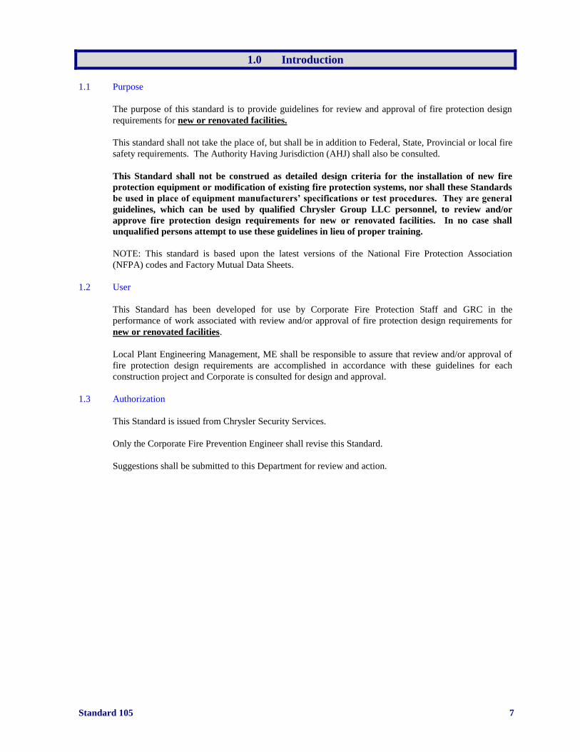
1.0 Introduction
1.1 Purpose
The purpose of this standard is to provide guidelines for review and approval of fire protection design
requirements for new or renovated facilities.
This standard shall not take the place of, but shall be in addition to Federal, State, Provincial or local fire
safety requirements. The Authority Having Jurisdiction (AHJ) shall also be consulted.
This Standard shall not be construed as detailed design criteria for the installation of new fire
protection equipment or modification of existing fire protection systems, nor shall these Standards
be used in place of equipment manufacturers’ specifications or test procedures. They are general
guidelines, which can be used by qualified Chrysler Group LLC personnel, to review and/or
approve fire protection design requirements for new or renovated facilities. In no case shall
unqualified persons attempt to use these guidelines in lieu of proper training.
NOTE: This standard is based upon the latest versions of the National Fire Protection Association
(NFPA) codes and Factory Mutual Data Sheets.
1.2 User
This Standard has been developed for use by Corporate Fire Protection Staff and GRC in the
performance of work associated with review and/or approval of fire protection design requirements for
new or renovated facilities.
Local Plant Engineering Management, ME shall be responsible to assure that review and/or approval of
fire protection design requirements are accomplished in accordance with these guidelines for each
construction project and Corporate is consulted for design and approval.
1.3 Authorization
This Standard is issued from Chrysler Security Services.
Only the Corporate Fire Prevention Engineer shall revise this Standard.
Suggestions shall be submitted to this Department for review and action.
Standard 105 8
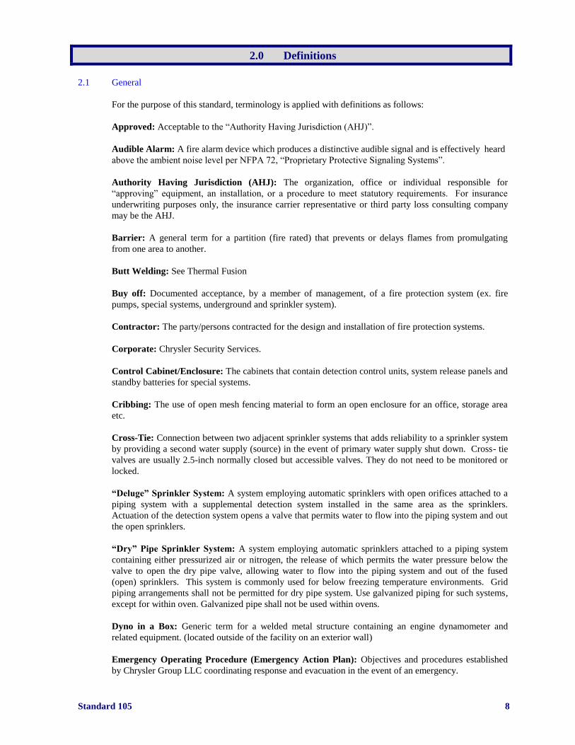
2.0 Definitions
2.1 General
For the purpose of this standard, terminology is applied with definitions as follows:
Approved: Acceptable to the “Authority Having Jurisdiction (AHJ)”.
Audible Alarm: A fire alarm device which produces a distinctive audible signal and is effectively heard
above the ambient noise level per NFPA 72, “Proprietary Protective Signaling Systems”.
Authority Having Jurisdiction (AHJ): The organization, office or individual responsible for
“approving” equipment, an installation, or a procedure to meet statutory requirements. For insurance
underwriting purposes only, the insurance carrier representative or third party loss consulting company
may be the AHJ.
Barrier: A general term for a partition (fire rated) that prevents or delays flames from promulgating
from one area to another.
Butt Welding: See Thermal Fusion
Buy off: Documented acceptance, by a member of management, of a fire protection system (ex. fire
pumps, special systems, underground and sprinkler system).
Contractor: The party/persons contracted for the design and installation of fire protection systems.
Corporate: Chrysler Security Services.
Control Cabinet/Enclosure: The cabinets that contain detection control units, system release panels and
standby batteries for special systems.
Cribbing: The use of open mesh fencing material to form an open enclosure for an office, storage area
etc.
Cross-Tie: Connection between two adjacent sprinkler systems that adds reliability to a sprinkler system
by providing a second water supply (source) in the event of primary water supply shut down. Cross- tie
valves are usually 2.5-inch normally closed but accessible valves. They do not need to be monitored or
locked.
“Deluge” Sprinkler System: A system employing automatic sprinklers with open orifices attached to a
piping system with a supplemental detection system installed in the same area as the sprinklers.
Actuation of the detection system opens a valve that permits water to flow into the piping system and out
the open sprinklers.
“Dry” Pipe Sprinkler System: A system employing automatic sprinklers attached to a piping system
containing either pressurized air or nitrogen, the release of which permits the water pressure below the
valve to open the dry pipe valve, allowing water to flow into the piping system and out of the fused
(open) sprinklers. This system is commonly used for below freezing temperature environments. Grid
piping arrangements shall not be permitted for dry pipe system. Use galvanized piping for such systems,
except for within oven. Galvanized pipe shall not be used within ovens.
Dyno in a Box: Generic term for a welded metal structure containing an engine dynamometer and
related equipment. (located outside of the facility on an exterior wall)
Emergency Operating Procedure (Emergency Action Plan): Objectives and procedures established
by Chrysler Group LLC coordinating response and evacuation in the event of an emergency.
Standard 105 9
Explosive Limits (Range): Minimum concentration of vapor to air below which (LEL) or above which
(UEL) propagation of flame will not occur in the presence of an ignition source.
Fire Partition: An interior wall that serves to restrict the spread of fire (subdivision of a fire area), but
does not qualify as a firewall.
Fire Proofing: Protective covering material applied to structural floor and wall assemblies (3/8 inch to 4
inches in thickness) intended to provide a fire resistance rating.
Firewall: A wall of sufficient durability and stability to withstand the effects of most severe, anticipated
fire exposure between areas of a building.
GRC: Global Risk Consultants (Chrysler Group LLC’s 3rd
party Loss Consultants)
HDPE: High density polyethylene
High Speed Water Spray (Deluge) System: A suppression system for the high hazard paint spray areas
designed to rapidly detect fire and subsequently provide water to the protected area through special
(Bete) nozzles connected to Cla-Valves.
High Volume Low Speed Fan: A ceiling fan that is approximately 6 ft to 24 ft in diameter with a
rotational speed of approximately 30 to 70 revolutions per minute.
Infrared Detection (IR): A device that is responsive to radiant energy outside the range of human vision
(above 7700 Angstroms) to sense the presence of flame as manufactured by a licensed and qualified fire
detection contractor.
Manual Pull Station: A device that actuates a fire alarm system.
Manual Release Station: A device that actuates a fire suppression system.
ME: Chrysler Manufacturing Engineering Group
NEMA 12: National Electrical Manufacturers Association reference to a water and oil resistant type of
enclosure
Operating Facility: A building or complex owned by Chrysler Group LLC for production, storage or
office use
Outside Stem & Yoke (OS&Y) Valve: A sprinkler system control valve where the stem position
indicates whether the valve is open or shut
Parapet: A portion of an exterior wall, fire wall, or party wall that extends above the roof line to prevent
fire spread along a roof.
Platform: An elevated horizontal structure, wider than 4 feet, that is supported from the floor.
Post Indicator Valve: A valve on a private fire protection water distribution system that controls supply
to individual sprinkler systems.
“Pre-Action” Sprinkler System: A system employing automatic sprinklers attached to a piping system
containing air (pressurized or not) with a supplemental fire detection system installed in the same area as
the sprinklers. Actuation of the detection system opens a valve that permits water to flow into the piping
and out any fused (open) sprinklers. Double interlocked type pre-action systems (mechanical and not
electric) shall be used at Chrysler Group LLC facilities.
Proprietary Protection Signaling System: A signaling system that serves properties under one
ownership from a central “on site” constantly attended supervising station.
Standard 105 10
Process Main: A dedicated interior (minimum 10-inch) fire main connected to opposite sides of the
underground fire main for the paint shop. Each connection to the underground main must have a control
valve on each riser (prefer PIV type) and one accessible normally open valve located in the center.
Only high-speed deluge systems shall be supplied (connected) to this main. Process main will be posted
with signs stating it is cross-connected. Auxiliary drains will be provided as necessary to properly drain
the system. NOTE: Plant may require that a swing check valve be provided on each end of the process
main. If swing check valves are provided, hydraulic calculations shall be based upon entire flow coming
through the longest leg of the process main and not split the required flow for the high-speed deluge
systems. Effort should be made to not have check valves installed.
Sectional Control Valve (SCV): An indicating type valve that controls fire water main
distribution. Sectional control valves isolate fire loops into sections that include no more than five
sprinkler system components.
Special System: A fire protection system designed to protect special hazard areas i.e. carbon dioxide,
HFC-227ea (FM-200), AFFF, Pro-inert, water spray, HFC-125 (ECARO), and water mist.
Standard: This Corporate Standard. Latest edition can be found at
www.globalriskconsultants.com/chrysler and use word - “contractor” – for user name and password.
Stopper Cover: A clear plastic hinged device to protect a manual release.
Temperature Rating: Predetermined-melting point (temperature) at which the fusible link (metal alloy)
of the sprinkler head fuses (operates). Also, predetermined temperature at which the glass bulb breaks
causing glass bulb sprinkler head to operate.
Thermal Fusion: Joining method using preformed pipe ends in conjunction with a hot plate heater used
to join HDPE pipe.
Ultraviolet Detection (UV): A device that is responsive to radiant energy outside the range of human
vision (below 4,000 nm or 400 Angstroms) to sense the presence of flame as manufactured by a licensed
and qualified fire detection contractor.
Ultraviolet/Infrared Detection (UV/IR): A device that uses the ultraviolet and infrared detection
principles to sense the presence of flame (both UV and IR sensors must be activated to release the
suppression agent) as manufactured by a licensed and qualified detection contractor.
G4S Secure Solutions (G4S): The contract security company that provides 24/7 security coverage at all
Chrysler Group LLC facilities.
Wall Post Indicator Valve: A control valve that is mounted on a building wall.
Wall Sectional Control Valve (WSCV): A sectional control valve that is mounted on a building wall.
Water Hammer: The effect of pressure rise (pipe rupture) that may accompany a sudden change in the
velocity of the water flowing in a pipe.
“Wet” Pipe Sprinkler System: A system employing automatic sprinklers attached to a piping system
containing water and connected to a water supply so that water discharges immediately from any fused
(open) sprinklers.

Standard 105 11
3.0 References
3.1 General
The following references provide fire protection standards and code requirements that shall be used in
conjunction with the established guidelines of this Standard and a Highly Protected Risk (HPR)
insurance carrier.
These codes shall be applied where they have been adopted as law by a particular state government or
authority and where they supersede the listed references.
3.2 National Fire Protection Association (NFPA) Standards and Factory Mutual (FM) Data Sheets.
(Latest edition shall be used by contractors)
NFPA 12 & Installation of Carbon Dioxide Fire Protection Systems
FM 4-11N
NFPA 2001 Clean Agent Fire Extinguishing Systems including HFC-227ea (FM-200) and HFC-
125 (ECARO) Fire Protection Systems
NFPA 13 & Installation of Sprinkler Systems
FM 2-8N & 8-9 (includes protection of various storage arrangements)
NFPA 13 & Installation of ESFR Sprinklers
FM 2-2
NFPA 15 & Water Spray Fixed Systems for Fire Protection
FM 4-1N
NFPA 17 & Dry Chemical Extinguishing Systems
FM 4-10
NFPA 17A Wet Chemical Extinguishing Systems
NFPA 20 & Installation of Centrifugal Fire Pumps
FM 3-7N
NFPA 24 Private water main and associated equipment
NFPA 26 Supervision of Valves Controlling Water Supplies
NFPA 70 National Electric Code (NEC)
NFPA 72 & Fire Detection and Alarm Systems
FM 5-2 & 5- 5
NFPA 77 Static Electricity
NFPA 203M & Roof Coverings
FM 1-28 & 1-29
NFPA 204M Smoke & Heat Venting
NFPA 241 & Construction, Alteration & Demolition Operations
FM 1-0
NFPA 251 & Fire Tests for Building Construction & Materials
FM 1-4
Standard 105 12
NFPA 601 Guard Service in Loss Prevention
NFPA 602 Guard Operations in Fire loss Prevention
NFPA 750 Water Mist Fire Protection Systems
3.3 National Fire Protection Association (NFPA)
Fire Protection Systems - Inspection, Test and Maintenance Manual (NFPA)
Industrial Fire Hazards Handbook - NFPA
3.4 Fire Protection Handbook (NFPA)
3.5 Underwriters Laboratories (UL), Inc.
Fire Protection Equipment List
3.6 FM Global
Approval Guides
Data Sheets
3.7 Industrial Risk Insurers (now known as XL)
Interpretive Guides
3.8 Canadian Standards/Codes
Canadian Standards/Codes associated with items covered in this Standard shall be adhered to by
Canadian operations where they supersede the references listed above.
3.9 Building Codes
IBC (International Building Code) and IFC (International Fire Code)
BOCA (Basic/National Building Code)
Uniform Building Code (UBC)
Southern Building Code (SBC)
American Society of Mechanical Engineers (ASME)
Boiler & Unfired Pressure Vessel Code
Chrysler Group LLC (ME)
84-260-1632 “Chrysler Group LLC General Conditions for Construction Contractors”
All applicable “Manufacturing Technical Instructions” (MTI’s) and “Safety Manufacturing Instructions”
(SMI’s)
Chrysler Group LLC Fire Protection Standards
101 - “Paint Spray Operations” 102 - “Material Storage”
103 - “Acceptance Test Standards” 104 - “Fire Protection Equipment
Maintenance Standards”
Standard 105 13
4.0 General
4.1 Introduction
This Standard is intended to provide guidelines for review and approval of fire protection design
requirements for new or renovated facilities.
Fire barriers, mechanical systems, fire suppression, detection, and alarms systems are provided to act in
the unlikely event of a fire. Review and approval of fire protection design requirements for new or
renovated facilities are required to achieve acceptable levels of fire protection for Chrysler Group LLC
design projects. This objective is accomplished by conveying fire protection design parameters to
architects and contractors of design projects. This Standard is intended to provide fire protection
guidelines for design that is acceptable to Corporate and GRC.
.
The information provided herein is generic in nature. Specific information for particular equipment or
systems shall be obtained from the applicable Standards and GRC
4.2 Authority
Review and approval of fire protection design requirements for new or renovated facilities shall be
performed in accordance with this Standard.
Review and approval of all fire protection design shall be the responsibility of Corporate and GRC.
Design of all fire protection shall be in accordance with the applicable standards and requirements of the
Authority Having Jurisdiction (AHJ).
Review and approval of the fire protection design shall be coordinated with the following:
- Corporate
- Installing Contractor
- Third Party Loss Consultant (GRC)
Fire protection design shall be in conformance with system design drawings, associated calculations,
applicable codes and standards, and this Standard.
4.3 Equipment
Personnel from Corporate and GRC shall approve all fire protection equipment installed in accordance
with this Standard.
All equipment in accordance with this specification shall be Underwriters Laboratories (UL) listed, FM
approved and/or equivalent as acceptable to Corporate and GRC.
Once a manufacturer’s equipment is selected for use in accordance with this standard, the same
manufacturer’s equipment shall be used to the extent possible to supply compatible equipment for the
specific fire protection systems throughout the plant.
4.3.1 Proprietary Equipment
Fire Hose (light-weight) - Snap-Tite (National Fire Hose), NPM 78-085-1750
Fire Hose (heavy-weight) - Snap-Tite (National Fire Hose), NPM 78-085-1751
Fire Hose Nozzle - Fog Nozzle Lexan, NPM 78-085-2532
Fire Hose Holder (in-plant use) - SLB-100, NPM 78-085-1747
Fire Hose Reel 26”(in plant use) - Hose reel, NPM 78-085-2800
Fire Hose Holder Cover - SLB-100 cover, NPM 78-085-0978
Fire Hose Reel Cover 26” - Hose reel cover, NPM 78-085-0965
Water flow switches - Potter Model VSR-F
Standard 105 14
4.4 Approvals
As of November 1, 2005 Chrysler Group LLC 3rd
party loss prevention consulting services are provided
by Global Risk Consultants (GRC).
Approval is required from GRC and Corporate for design of new buildings, additions, or
renovations/changes that are performed in accordance with this Standard. Approval from GRC shall be
in the form of a formal letter addressed to the contractor who submitted the plans.
For approval purposes, paper copies of all concept drawings, construction drawings, shop drawings,
acceptance test certificates, system impairment notices, and system modifications shall be submitted to:
- Corporate Fire Protection Engineer (1 paper copy)
Chrysler Security Services
CIMS 485-01-52
- The Technical Service Office for GRC listed below: (3 paper copies minimum)
Mr. James Faitel
Senior Consultant
Global Risk Consultants
14058 Edgewood Street
Livonia, Michigan 48154-5334
(734) 513-5070 phone
(313) 268-2965 mobile
(734) 513-7383 fax
e-mail: [email protected]
- Other individuals and/or companies as directed by the Corporate Fire Protection Engineer
THE 90% DESIGN DRAWINGS SHALL BE REVIEWED BY CORPORATE FIRE, PLANTS
SECURITY, PLANT SECURITY MANAGER AND THE LOSS PREVENTION CONSULTING
COMPANY PRIOR TO THE START OF THE JOB.
Requirements that are referenced in this Standard shall be incorporated into contract specifications for all
work/projects.
4.5 Testing
Acceptance tests shall be performed on all newly installed or modified equipment/systems in accordance
with this Standard. Renovations or changes to a fire protection system may require that an acceptance test
be performed.
Acceptance testing shall be coordinated by the General Contractor after being notified by the installing
contractor that the system is ready for testing.
The following personnel shall be notified of the test by the General Contractor at least 5 days before the
test:
Chrysler Security Services
Site Contract Security Manager
Third Party Loss Consultants (GRC)
Local Plant Engineering
AHJ
Standard 105 15
5.0 Underground Fire Water Supply Mains and Interior Mains
Located within Roof Trusses
5.1 Pipe
Pipe used in underground water mains (loops) for site fire protection shall be a minimum of ten inches in
internal diameter. Six and eight inch pipes (internal diameter) are not acceptable due to excessive
friction loss characteristics. Water conditions shall dictate the schedule of pipe.
Required depth of cover for underground piping shall be in accordance with frost penetration in regional
charts that indicate required depth of cover. Refer to latest edition of NFPA 13 (see attached chart on
depth of bury).
Private fire service mains shall be looped or “gridded” to provide a dual water supply feed arrangement.
NOTE: Interior fire water mains within roof trusses shall only be installed with approval from Corporate
and GRC. Of major concern is the type of occupancies located beneath the interior fire main and for 20
feet in all directions. Not permitted are such occupancies as storage of combustibles, machining
operations using combustible cutting oil, hydraulic oil system under pressure, etc.
Riser lead-ins shall be 8-inch to the alarm check valve. Process Mains (refer to Standard #101) shall be a
minimum of 10-inches (internal diameter).
Sprinkler systems shall be designed so that one 8-inch lead-in main shall supply water to one sprinkler
riser/system. Manifolded sprinkler risers shall not be permitted without written permission from
Corporate.
Except for lead-in mains, water mains shall not be installed under buildings. Risers shall be located
adjacent to exterior walls unless written permission is obtained from Corporate and GRC.
Where existing underground mains and or lead-ins will be abandoned under a new floor slab, the entire
abandoned main shall be filled with grout and capped at both ends. The grout mixture and fill method
shall be specified by Chrysler Manufacturing Engineering Group (ME) and/or the architect.
Pipe type shall be restricted to the following:
- Cast iron
- Ductile iron
- Steel
- Polyvinyl Chloride (PVC) NOTE: Tracing tape should be installed per contract documents
- High Density Polyethylene (HDPE) Class 200: Tracing tape should be installed per contract
documents
Piping fittings and joints shall be restricted to the following methods:
- Welding
- Mechanical fittings
- Rolled Groove
- Threaded (flanged)
NOTE: Meg-A-Lug or similar type mechanical fittings shall not be used unless thrust blocks are
also used. GRC shall be contacted during design phase if such fittings shall be used
- Thermal Fusion (Butt) Welding: Used only for HDPE pipe installation

Standard 105 16
Non Metallic Pipe and Fittings:
All nonmetallic pipes shall be FM approved and Class 200 pressure rated. PVC pipe shall only be
coupled using mechanical joints. HDPE pipe can be joined using butt welding, mechanical joints or
“push on” bell and spigot.
All butt welding operations shall be conducted by trained and certified personnel.
Metallic Pipe and Fittings:
Schedule 10 and schedule 40 metallic pipes, for use in sprinkler systems, shall be UL or FM approved.
All pipes 6 inches and smaller (internal diameter) must have a MIC coating applied by the Mill. Eight
inch pipes and larger shall be schedule 10 MIC coated on special order from the Mill. A letter from the
Mill stating that the pipe has MIC coating is required from the contractor. This letter shall be submitted
to ME and as part of the plan review to GRC.
If the pipe is painted in the field or shop, the pipe id markings are not legible. In this case the Chrysler
ME Project Engineer or a member of Corporate must accept the pipe prior to painting.
Galvanized coated pipe is not acceptable for use in wet systems as an alternative to MIC coated pipe.
5.2.1 Cathodic Protection
If stray currents are suspected in the soil, all joints shall be bonded with low-resistance metallic ground
connections. A corrosion engineer/consultant is required to provide information on the corrosiveness of
the soil. NOTE: It maybe more cost-effective to just provide cathodic protection.
Methods, if required, for cathodic protection shall be sacrificial nuts, bituminous wrapping and coating,
or a combination of the above. A minimum of two sacrificial zinc anode nuts per connection is required.

Standard 105 17
5.3 Thrust Blocks, Piping Anchoring & Trench Backfill
Pipe anchoring is required to prevent joints from separating at bends, tees, plugs, and changes in pipe
diameter and hydrants due to unbalanced thrust created by water flow. Pipe anchoring is provided by
either using thrust blocks, rods and clamps, or locked mechanical fittings. No Meg-A-Lug (or similar
type) fittings shall be installed without thrust blocks. GRC shall be contacted during design phase if such
fittings shall be used.
Thrust blocks are constructed of concrete and are cast-in-place. Sizes are determined by code. See NFPA
13 and 24. An acceptable method (sheet metal, cinder blocks or plywood) shall be utilized to separate
adjacent thrust blocks when valves or hydrants are in close proximity to each other.
Any deviation from the above paragraphs, or other pipe anchoring methods, shall be referred to GRC
prior to submittal of plans for review.
The fire protection underground main installer or the Site General Contractor is responsible to
photograph all poured thrust blocks and to number them according to a plot plan of the site with all
hydrants, tees, valves etc labeled (these would be points where thrust blocks will be poured. As the job
progresses these photos shall be reviewed by a member of Corporate. These printed photos shall be left
on the job site in the Construction or ME trailer.
An alternative is to leave all thrust blocks uncovered for viewing by a member of the Corporate and/or
GRC.
When using HDPE underground piping follow the manufacturer’s instruction.
Standard 105 18
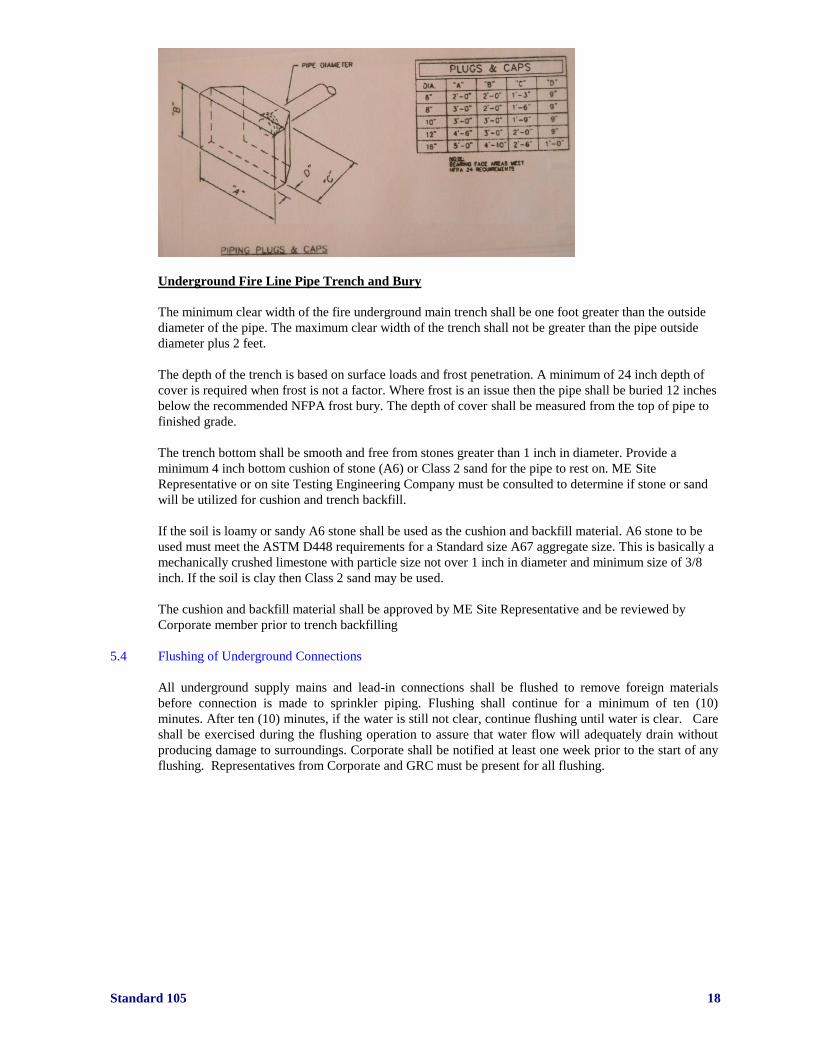
Underground Fire Line Pipe Trench and Bury
The minimum clear width of the fire underground main trench shall be one foot greater than the outside
diameter of the pipe. The maximum clear width of the trench shall not be greater than the pipe outside
diameter plus 2 feet.
The depth of the trench is based on surface loads and frost penetration. A minimum of 24 inch depth of
cover is required when frost is not a factor. Where frost is an issue then the pipe shall be buried 12 inches
below the recommended NFPA frost bury. The depth of cover shall be measured from the top of pipe to
finished grade.
The trench bottom shall be smooth and free from stones greater than 1 inch in diameter. Provide a
minimum 4 inch bottom cushion of stone (A6) or Class 2 sand for the pipe to rest on. ME Site
Representative or on site Testing Engineering Company must be consulted to determine if stone or sand
will be utilized for cushion and trench backfill.
If the soil is loamy or sandy A6 stone shall be used as the cushion and backfill material. A6 stone to be
used must meet the ASTM D448 requirements for a Standard size A67 aggregate size. This is basically a
mechanically crushed limestone with particle size not over 1 inch in diameter and minimum size of 3/8
inch. If the soil is clay then Class 2 sand may be used.
The cushion and backfill material shall be approved by ME Site Representative and be reviewed by
Corporate member prior to trench backfilling
5.4 Flushing of Underground Connections
All underground supply mains and lead-in connections shall be flushed to remove foreign materials
before connection is made to sprinkler piping. Flushing shall continue for a minimum of ten (10)
minutes. After ten (10) minutes, if the water is still not clear, continue flushing until water is clear. Care
shall be exercised during the flushing operation to assure that water flow will adequately drain without
producing damage to surroundings. Corporate shall be notified at least one week prior to the start of any
flushing. Representatives from Corporate and GRC must be present for all flushing.
Standard 105 19
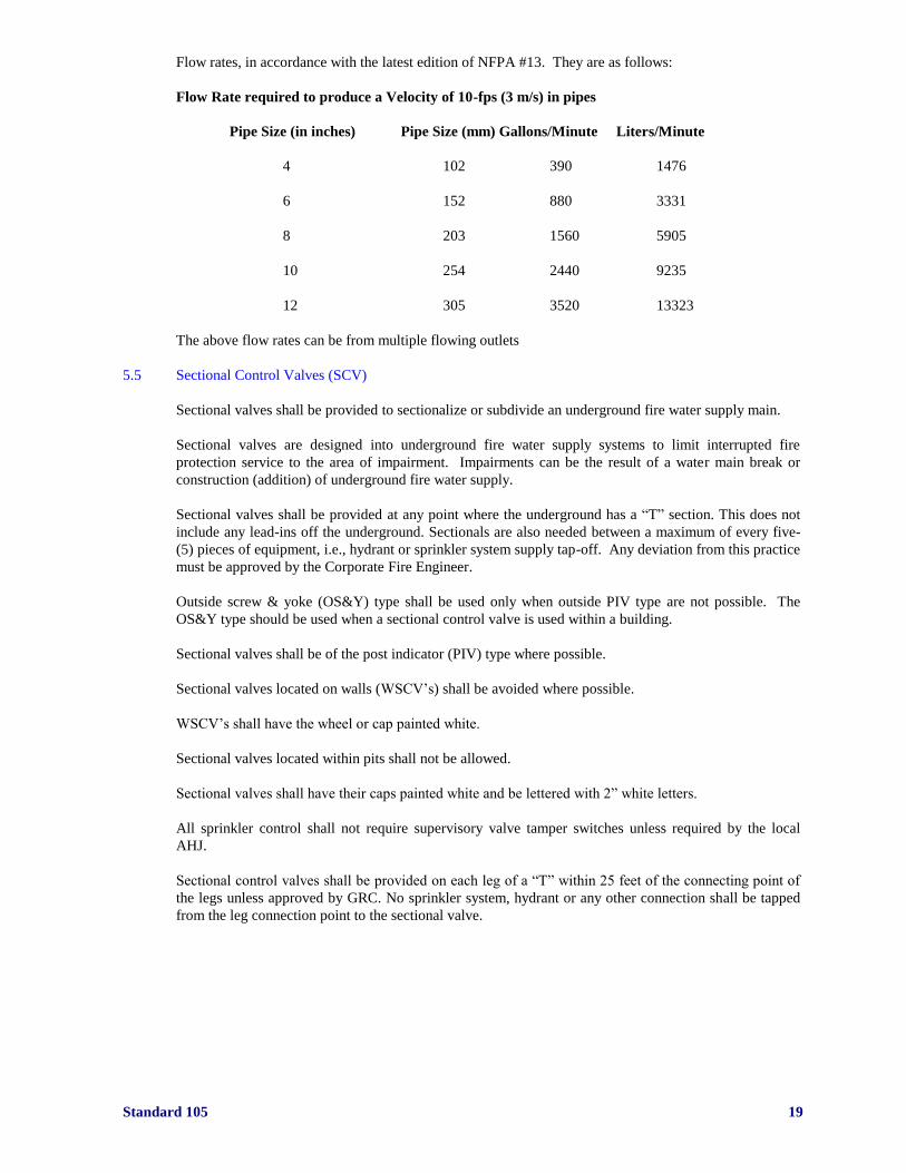
Flow rates, in accordance with the latest edition of NFPA #13. They are as follows:
Flow Rate required to produce a Velocity of 10-fps (3 m/s) in pipes
Pipe Size (in inches) Pipe Size (mm) Gallons/Minute Liters/Minute
4 102 390 1476
6 152 880 3331
8 203 1560 5905
10 254 2440 9235
12 305 3520 13323
The above flow rates can be from multiple flowing outlets
5.5 Sectional Control Valves (SCV)
Sectional valves shall be provided to sectionalize or subdivide an underground fire water supply main.
Sectional valves are designed into underground fire water supply systems to limit interrupted fire
protection service to the area of impairment. Impairments can be the result of a water main break or
construction (addition) of underground fire water supply.
Sectional valves shall be provided at any point where the underground has a “T” section. This does not
include any lead-ins off the underground. Sectionals are also needed between a maximum of every five-
(5) pieces of equipment, i.e., hydrant or sprinkler system supply tap-off. Any deviation from this practice
must be approved by the Corporate Fire Engineer.
Outside screw & yoke (OS&Y) type shall be used only when outside PIV type are not possible. The
OS&Y type should be used when a sectional control valve is used within a building.
Sectional valves shall be of the post indicator (PIV) type where possible.
Sectional valves located on walls (WSCV’s) shall be avoided where possible.
WSCV’s shall have the wheel or cap painted white.
Sectional valves located within pits shall not be allowed.
Sectional valves shall have their caps painted white and be lettered with 2” white letters.
All sprinkler control shall not require supervisory valve tamper switches unless required by the local
AHJ.
Sectional control valves shall be provided on each leg of a “T” within 25 feet of the connecting point of
the legs unless approved by GRC. No sprinkler system, hydrant or any other connection shall be tapped
from the leg connection point to the sectional valve.
Standard 105 20
5.6 Post Indicator Valves (PIV)
Post indicator valves shall be provided to sectionalize the piping system and, thus, limit the area subject
to a single impairment.
Outside screw & yoke (OS&Y) type shall be used only when outside PIV type are not possible.
Wall mounted post indicator valves shall be used only when outside PIV are not possible and the wall is
of fire rated construction. If possible, PIV’s shall be located a minimum of one-half the height of a
building away from the building but no less than 40 feet.
Post indicator valves located on walls (WPIV) shall be avoided.
Post indicator shall be numbered with 2” white numbers.
5.7 Outside Screw & Yoke Valves (OS&Y)
Outside screw & yoke valves (OS&Y) are typically installed for indoor water supply and sprinkler
system sub valves.
5.7.1 Butterfly Valves
Butterfly type valves are not acceptable for use in Chrysler Group LLC fire protection systems.
5.7.2 Process Loop – refer to Standard #101 and definition section)
Process loops, used for high-speed deluge systems, shall have equipment sub-valves where the protected
equipment has more than 20 sprinkler heads. A sectional central valve shall be installed to split the
process loop in half. This valve shall be located no more than five feet from finished floor accessibility.
The location on the fire water main shall be such that an impairment does not “take down” both the booth
wet pipe system and process loop with a common break. All sub systems off the process riser shall be a
minimum of 2½ inches and provided with an OS&Y type control valve and water flow switch.
5.8 Hydrants
Hydrants provide water supply from the site underground fire water main to mobile fire equipment for
distribution.
For new construction projects, if required by AHJ, hydrants shall be provided on the underground main.
Hydrant spacing shall be a maximum of 300 feet around the perimeter of a building/site. Hydrants shall
be located a minimum of 40 feet from a building (unless physically impossible). Wall hydrants shall only
be utilized if the underground is not “looped” and protection is required on the “un-looped” side.
Private yard hydrants shall be provided only with two 2½-inch outlets or as directed by local AHJ and
approved by Corporate and GRC. Where existing on hydrants, pumper connection outlet (normally 4 or
5 inch) shall be welded shut with concurrence of the local AHJ.
Hydrants shall be provided with drainage capability and threads compatible with those used by the local
Municipal fire department.
Hydrants shall be numbered with white 2” numbers
All hydrants shall be provided with a curb box control valve. This valve shall be located within 3 feet of
the hydrant water supply connection. The valve housing shall be extended four (4) inches above grade
unless it is installed in a roadway or sidewalk. If the valve is installed in a roadway or sidewalk it shall be
at grade level.
Provide a hydrant wrench for every three (3) hydrants installed. This wrench shall be given to the local
G4S Secure Solutions (G4S) Site Security Manager or on-site security representative.

Standard 105 21
5.9 Fire Department Connections (FDC)
Fire department connections shall be incorporated in private water fire protection systems as a
supplementary water supply to a city or fire pump supply (for pressure). Fire pumper connections shall
be installed on the discharge side of the fire pump(s). Additional fire department connections may be
required in conjunction with sprinkler systems if building size or special hazard warrants. Fire
department connections are not required for each sprinkler system. Each connection (tie-in) from a City
main shall have a fire department connection.
Number and type of outlets shall be dictated by local AHJ.
5.10 Valves in Pits
Backflow prevention devices shall be located above ground. These devices can be installed in a fire
pump house, in a pump room of a building or “hot box”.
5.10.1 Fire Hose Valves and Drops
NFPA No. 13, 2007 edition does not require 1.5-inch fire hose drops or hose stations if approved by
local AHJ. If fire hose drops are required by local AHJ, fire hose control valves (1.5”) must have built-in
pressure limiting device that limits pressure to 80-psi. Pressure limiting disks shall not be used as a
method to reduce pressure.
5.11 Hydrostatic Tests
All new piping, including underground piping and fire department connections, shall be hydrostatically
tested at not less than 200 PSI (13.8 bars) for two hours.
When the maximum pressure in the system is greater than 150 PSI (10.3 bars), the test pressure shall be
50 PSI (3.4 bars) above the maximum system pressure. The test pressure shall be read at a gauge
installed at the lowest elevation of the system or portion of the system being tested. Gauge(s) used shall
be approved by member of Corporate and GRC.
No visible leakage shall be noted from the sprinkler piping. The amount of leakage for underground
piping shall not exceed two quarts (1.89 liters) per hour per 100 gaskets or joints. This permissible
leakage is not respective of (not directly proportional to) pipe diameter. The amount of leakage shall be
measured by pumping from a calibrated container to maintain required pressure during the two (2) hour
test. The amount of allowable leakage for valves is one fluid ounce per inch valve diameter per hour (30
milliliters) for each valve isolating the tested pipe section.
Hydrostatic testing of underground piping shall be performed before the trench is completely back-filled.
Piping shall be covered between joints to hold the piping in place. Joints, however, shall be left un-
covered so they can be observed for leakage during the test. When test “blanks” are used to isolate a
portion of the system, only self-indicating types shall be used. Each blank, if used, shall be inventoried
so that they can be totally removed from the system upon completion of testing.
Corporate shall be notified at least one week prior to the start of any hydrostatic testing. A representative
of Corporate and/or GRC or an approved representative must be present for all hydrostatic testing.
Upon buy off of a system all associated water supply control valves shall be identified, locked and
added to the Plant control valve inspection form.
Sprinkler installations involving 20 sprinklers or less are not required to be hydrostatically tested or
submitted to GRC for approval.

Standard 105 22
5.12 Backflow Prevention and Low Suction Pressure Regulating Valves
Connections of site water to a city main shall have a check valve in the tie-in line to prohibit backflow of
site water into the city water supply. Local and state building codes shall be consulted for required or
allowed variations of check valve arrangements.
Types of backflow prevention are as follows:
- Low Pressure Backflow Prevention Assembly
- Double Check Valve Assembly
- Check Valve
- Detector Check Valve
A low suction pressure regulating valve may be required by the local authority having jurisdiction (AHJ)
to prevent flowing water that will cause the residual pressure to drop below a predetermined rate, usually
20 PSI. These valves are not really backflow preventers.
Backflow preventers shall be FM approved. Install the backflow preventer, if required by the local AHJ,
on the discharge side of the fire pump. The local AHJ may require the backflow preventer to be installed
on the suction side of the pump.
Pressure loss of the backflow preventer shall be incorporated into the sprinkler system design hydraulics.
All devices shall be located above ground.
Standard 105 23
6.0 Water Supply
6.1 Suction Supply
Water supply to a fire pump shall be from a reliable supply source with adequate volume and pressure to
meet the required demand. Water supply sources are city water supply, elevated storage tanks, ground
level storage tanks, or underground storage tanks as approved by Corporate and GRC.
A connection to a city water supply shall be provided in accordance with the latest edition of NFPA #13
and #24. The connection, thrust blocks, backflow prevention device, metering, shut-off valves and
backfill shall be considered when connecting to a city water supply.
6.1.1 Suction Tank
An exterior manual tank level float and interior electronic water level indicator shall be installed on all
ground level suction tanks.
A temperature-indicating device shall also be installed and shall be located in the pump house.
A by-pass piping system with OS&Y type control valve shall be provided around the automatic fill valve
(altitude valve) for overflowing the suction tank manually. If an existing altitude control valve is replaced
then this bypass is required to be installed
Suction tank shall have a connection from the tank to the pressure sensing line of the altitude valve. The
sensing line of the altitude valve shall not be connected off the fire pump suction main. A strainer shall
be provided on this line for easy removal of debris and prevent debris from entering altitude valve
sensing device.
Overflow piping from tank shall discharge approximately one foot above ground level to a concrete
splash pad. Free-falling of water from overflow outlet will not be allowed.
Suction tanks shall be provided with a heating system such that a minimum water temperature of 42°F
throughout tank shall be maintained.
The suction tank shall be sized based upon the greatest sprinkler system design demand and hose stream
allowance. The water supply duration shall be for a minimum of two (2) hours.
6.2 Fire Pump House
Fire pump houses shall be of non-combustible construction.
Fire pump houses shall be 100% protected by sprinklers. The sprinkler riser shall be located in the fire
pump house and provided with an OS&Y type control valve and water flow switch. Sprinkler system
water supply shall be from the discharge side of the fire pump.
The fire pump house shall be heated (40°F.) to prevent fire pumps and piping from freezing.
Fire pump house heaters shall be permanently installed.
If diesel engine-driven fire pump(s) are used, louvers operated by the fire pump controller are required to
provide cooling air to the fire pump(s). The louvers shall be located to ensure that any water mains within
the fire pump house are not exposed to cold weather drafts or sub-freezing temperatures.
Fire pump houses shall be locked. Keys and access shall be provided in accordance with a plant’s
emergency operating procedure. All control valves located in the pump house shall be locked in the
proper position.
Drainage shall be provided to prevent flooding of the fire pump house. All fire pumps shall sit on an
elevated pad.

Standard 105 24
If diesel engine-driven fire pumps are used, containment shall be provided for the entire quantity plus
50% of the diesel fuel in the event of a diesel fuel leak or spill. Presently, most installations use the tank-
within-a-tank arrangement for the storage of diesel fuel. The fuel oil tank supply shutoff valve shall be
locked in the open position
6.3 Fire Pumps
Fire pumps shall be provided where required to meet volume and pressure demands for a building/site
fire protection water supply system.
Fire pumps shall be listed by Underwriters Laboratories (U.L.) and FM Approved.
Fire pumps shall have a rated capacity sufficient to meet the largest fire protection system demand.
Fires pump location, size, driver type, and installation shall be in accordance with Corporate Fire
Prevention Engineer and GRC. The coupling for a fire pump/driver shall be a Falk T-10, drive-shaft type
or acceptable equal.
All fire pump couplings shall be a Falk T-10 or other FM approved metallic coupling only, no plastic
couplings. Alternatives such as all metal drive-shaft (U-joint) between the pump and driver are
acceptable as long as they are approved by FM.
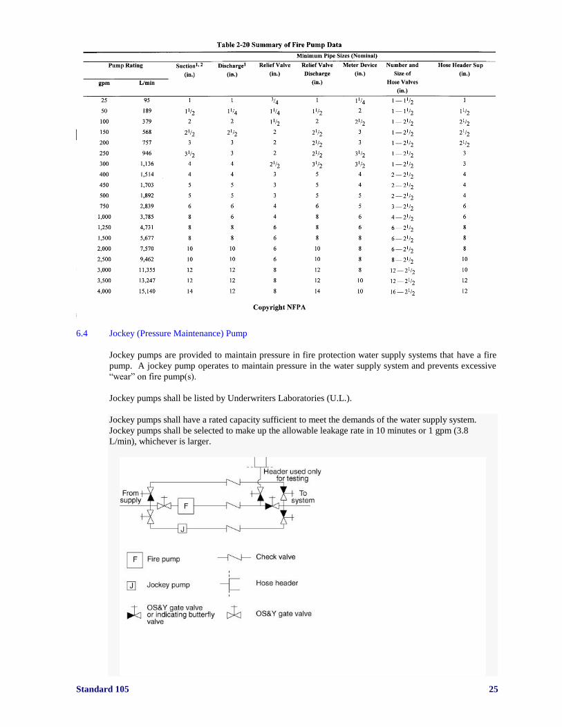
Fire pump flowmeters shall not be installed for testing purposes. A fire pump test header based on NFPA
20 requirements shall be installed and utilized for testing purposes. Fire pump test headers should be
flush with exterior wall of fire pump house in vertical position and be provided with 2.5-inch globe
control valves on each outlet. The outlets shall be vertical design.
The following settings are suggested based on the churn pressure of the fire pump:
Normal fire pump setting shall be as follows:
ON OFF
Jockey 140 150
First Main Pump 130 Manual Off
Second Main Pump 120 Manual Off
Any deviations from these settings shall be approved by Corporate and GRC.
If the facility is equipped with both a Diesel and Electric main fire pump driver the Diesel shall be
the first to start. NOTE: Corporate and GRC may vary this requirement based upon an analysis of
“churn” pressure and discharge of water from pressure relief valves. (See attached chart on fire pump
piping criteria)
Standard 105 25
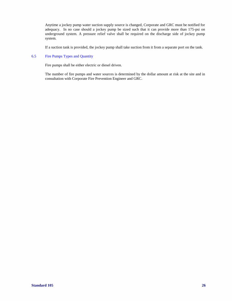
6.4 Jockey (Pressure Maintenance) Pump
Jockey pumps are provided to maintain pressure in fire protection water supply systems that have a fire
pump. A jockey pump operates to maintain pressure in the water supply system and prevents excessive
“wear” on fire pump(s).
Jockey pumps shall be listed by Underwriters Laboratories (U.L.).
Jockey pumps shall have a rated capacity sufficient to meet the demands of the water supply system.
Jockey pumps shall be selected to make up the allowable leakage rate in 10 minutes or 1 gpm (3.8
L/min), whichever is larger.
Standard 105 26
Anytime a jockey pump water suction supply source is changed, Corporate and GRC must be notified for
adequacy. In no case should a jockey pump be sized such that it can provide more than 175-psi on
underground system. A pressure relief valve shall be required on the discharge side of jockey pump
system.
If a suction tank is provided, the jockey pump shall take suction from it from a separate port on the tank.
6.5 Fire Pumps Types and Quantity
Fire pumps shall be either electric or diesel driven.
The number of fire pumps and water sources is determined by the dollar amount at risk at the site and in
consultation with Corporate Fire Prevention Engineer and GRC.
Standard 105 27
7.0 Roof Decks
7.1 General
Roof decks shall be minimum Class I-90 insulated steel deck for wind uplift (PSF) and FM Class 1 for
flame spread. If an insulated roof deck other than I-90 is specified contact Corporate and GRC
FM Global approves a number of special roof insulation and roofing “systems”. These systems are used
to provide components of the roof deck, including vapor barriers, insulation, wind up-lift resistance and
adhering material that provides fire safety and wind resistance.
The FM Approval Guide and Data Sheet 1-28 and 1-29 shall be reviewed when considering types of roof
deck for an installation. Items such as ground roughness and distance from a coastline shall be
considered in determining the type of roof system.
Approved proprietary roofing systems and components shall be provided in accordance with the Factory
Mutual Approval Guide.
All thermal barrier boards, including gypsum board, shall be fastened in accordance with FM Data Sheet
1-29.
7.2 Roof Coverings
Roof covering range from combustible wood shingles with no fire retardant treatment to coverings that
are effective against severe external fire exposure. Well-designed fire resistive roof coverings can
minimize the likelihood of fire spread from one building to another.
7.2.1 Roof Covering Classifications - Factory Mutual Global
An insulated steel deck roof is designated FM Class 1 when the roof is constructed with deck
components that have met Factory Mutual Global limitations on heat release rate during testing.
When heat release from a tested roof assembly exceeds those limitations, the roof is designated FM Class
2.
7.2.2. Roof Covering Classification - NFPA
Three classes of fire resistive roof coverings in accordance with NFPA are as follows:
Class Coverings: Include roof coverings that are effective against severe fire exposures. These coverings
are not readily flammable, do not “carry” or communicate fire, have a high degree of fire protection to
the roof deck, do not slip from position and possess no flying brand hazard. They do not require frequent
repairs to maintain their fire retardant properties.
Class B Coverings: Include roof coverings that are effective against moderate fire exposures. These
coverings are not readily flammable, do not readily “carry” or communicate fire, have a moderate degree
of fire protection to the roof deck, do not slip from position and possess no flying brand hazard. They
may require repairs to maintain their fire retardant properties.
Class C Coverings: Include roof coverings that are effective against minimal fire exposure. These
coverings are not readily flammable, do not readily “carry” or communicate fire, have a slight degree of
fire protection to the roof decks, do not slip from position and possess no flying brand hazard. They
require repairs or renewals to maintain their fire retardant properties.
Building codes commonly require Class “A” or “B” coverings wherever fire resistive construction is
required or within requirements of local codes. Class “C” roofing is appropriate for other buildings.
Many municipalities specify Class “C” as the minimum standard for roofing.
Standard 105 28
Chrysler Group LLC will only accept Class “A” roof covering installations and Factory Mutual
Class 1 approved roofing systems unless deviations are approved by Corporate and GRC.
7.3 Construction
Insulated steel deck is constructed by first securing rigid insulation board to the upper surfaces of the
deck with insulation fasteners. A waterproof covering is then installed above the insulation. The built-up
roofing type is three to five piles of roofing felts adhered to the insulation and to each other with hot tar
or asphalt.
The single-ply membrane covering is also widely used. The ply is fastened to the deck and adhered to
the insulation or loosely laid and covered with stone ballast.
When a vapor barrier or retardant is needed, this single ply sheet can be placed directly on the deck, or in
some cases. Adhered to a minimum thickness insulation board mechanically fastened to the deck.
Steel decks roofs shall have slight slopes to permit water run-off and to prevent puddles from forming.
Any roof decks not covered in the above sections shall be referred to the Corporate Fire Prevention
Engineer for approval and comments such as standing seam, single ply membrane etc.
7.4 Standing Seam Roof Systems
This system is used in pre-engineered building structures. The roof system must meet all FM criteria.
Standard 105 29
8.0 Fire Walls & Partitions
8.1 General
Firewalls are interior walls that provide a fire separation between areas of the same building. Firewalls
are designed to prevent the spread of fire into or within a building, and to assure that the barrier will not
collapse during fire exposure. Firewalls shall be designed to maintain structural integrity to the extent
that collapse of the structure on either side of the firewall will not cause the wall to collapse. To
withstand heat expansion effects, firewalls are commonly made thicker than would be required by normal
fire resistance ratings. Walls may be buttressed by cross walls or pilasters if of considerable height or
length. Fire resistance ratings for firewalls range from three to six hours.
Fire partitions subdivide a floor or building area and extend from the floor to the underside of the floor
above. Fire partitions may be constructed of non-combustible, limited combustible or protected
combustible material and shall be attached to and supported by structural members having fire resistance
at least equal to the requirement of the partition. A fire partition normally possesses less fire resistance
than a firewall and does not extend from the basement through the roof, as does a firewall. Fire
resistance ratings for partitions range from one-half to two hours.
Fire walls and partitions are commonly constructed of masonry, wood or metal studs using fire resistive
materials.
Exterior walls, interior partitions and floor/ceiling assemblies are components that define the
architectural layout of rooms in a building. These components are used to provide privacy, security, and
protection from the elements and noise control. They also provide fire protection by delaying or
preventing fire from spreading from one room to an adjacent room. IF THESE WALLS HAVE
URETHANE FOAM INSULATION AND ARE OVER 30 FEET HIGH THEN THEY MUST BE
FACTORY MUTUAL GLOBEL APPROVED. THIS REQUIREMENT IS FOR EXTERIOR
AND INTERIOR WALLS.
The effectiveness of a barrier in preventing flames from moving from one room to another depends upon
the fire resistant construction of the barrier, the fuel load in the room, applied loading on the structural
components, the construction features and the effect of openings and penetrations in the barrier.
The most common cause of fire movement from one room to an adjacent room is through unprotected
openings in barriers. Code requirements and heavy duty construction are often rendered ineffective
because of uncontrolled openings in a partition, i.e., doors, windows, grilles, ducts, and other openings in
conjunction with a lack of protection of openings.
Fire doors shall be UL listed or FM approved. NOTE: ULC in Canada.
All exterior metal foam (sandwich) panel walls shall be Factory Mutual approved when used for walls
over 30 feet in height
8.2 Fire Resistance
Building codes, through construction classification, identify fire resistive requirements of barriers.
Fire resistance ratings are determined by subjecting the barrier assembly to standard fire tests. Fire
resistance is the endurance time converted to duration in hours that is established by recognized
standards. Both combustible and non-combustible barriers can obtain fire resistance ratings from fire
tests. Fire doors and other protected openings shall have a fire resistance rating equal to or exceeding the
rating of the wall (partition).
Fire resistance of walls and partitions will delay or prevent flames from moving horizontally from one
room to an adjacent room. These assemblies are tested in accordance with NFPA #251, “Fire tests for
Building Construction and Materials”.

Standard 105 30
Large manufacturing and warehouse buildings are sub-divided into fire areas to limit the spread of fire.
Horizontal fire spread is limited by distance between building (as required by code) or by firewalls.
In multi-story buildings, vertical fire spread from one story to another is limited by the floor construction
and by wall enclosures around stairways, elevator shafts and other horizontal and vertical openings.
8.3 Application
Subdivision of a building through use of barriers is intended to independently limit property loss from a
single fire. However, fire suppression systems supplement passive barriers to provide an adequate fire
protection system. If sprinkler protection is impaired, reliance must be placed on passive barriers and
manual fire fighting operations for fire containment.
Area housing hazardous processes, equipment or materials shall be isolated from surrounding
occupancies. Paint mix rooms and paint operations shall be separated from metalworking operations and
other fuel and heat sources, flammable-liquid storage tanks from main-plant buildings, and storage from
manufacturing operations. Equipment or services of vital importance to uninterrupted production shall
also be separated from the fire or explosion hazards of surrounding buildings or occupancies. Power-
generation equipment shall be located in a segregated building. Power transformers and switchboards
shall be located in fire-resistive cutoff rooms or located outside. Storage of records and tracings shall be
in special vaults.
8.4 Parapets
Parapets prevent passage of fire over firewalls when the roof deck is combustible. Parapets shall extend
at least 30 inches above a combustible roof and shall be of non-combustible construction. Parapets shall
be an extension of the firewall, designed to break the continuity of embers and radiant heat from
spreading to an adjacent fire area. Class I insulated metal roof decks are not sufficiently combustible to
require parapets.
Standard 105 31
9.0 Smoke & Heat Venting
9.1 General
Ventilation is the planned and systematic removal of heat, smoke, and fire gases from a building.
Ventilation may be required in accordance with rescue efforts in order to protect occupants from smoke
and heat and to provide visibility and tenability during rescue operations.
Emergency exhaust (heat & smoke) vents shall be provided in storage areas and other high heat release
areas only when required by local codes and the AHJ.
Corporate and GRC do not required smoke and heat venting unless required by local AHJ.
Emergency exhaust wall vents shall be provided in conjunction with, but not in place of, fire rated walls
and fire detection and suppression systems.
Vents, where required, shall operate both automatically and mechanically. Automatically operated vents
shall be connected to the building/plant security system and designed to operate upon activation of the
fire alarm system or sprinkler system within that zone.
Vents shall be equipped to operate mechanically by provision of a fusible link. This link shall be one
temperature rating higher than the existing sprinklers in the area. For example, if sprinklers are 286°F,
use 360°F fusible links for heat and smoke vents.
Heat and smoke venting shall be provided at a ratio of 1 square foot per 30 square feet of room floor area
(1:30) or as required by local codes.
A powered exhaust option for up to 50 percent of required heat and smoke venting may be provided at a
ratio of 300 cubic feet per minute of exhaust volume per square foot of heat and smoke venting (300:1).
Dampers and smoke detectors shall be installed in ductwork/stacks in accordance with the Authority
Having Jurisdiction.
9.2 Vent Types
Heat and smoke vents are typically 16 to 100 square feet in area. Automatic vent operation is of two
types, i.e., fusible link type or “drop out” plastic. The fusible link type consists of a metal housing with
lids that depend upon a temperature rated fusible link to trip the lid mechanism. The drop out plastic
type depends upon a temperature sensitive, transparent or translucent thermoplastic dome that deforms
from its setting and falls out of the roof when heated beyond its temperature rating. Vents designated for
manual operation (in conjunction with automatic operation) are constructed with metal lids to resist
elevated fire temperatures and may be opened from the floor with wires and cables.
9.3 Explosion Relief Venting
Explosion relief venting (for the Paint Mix Room only) shall be provided at a ratio of 1 square foot per
50 cubic feet of volume (1:50). Explosion relief venting can be designed into either the roof or wall.
Explosion relief venting shall relieve at 20-25 pounds per square foot, but in no case less than the design
wind load pressure.
Explosion resistance shall be 100-125 pounds per square foot, but in no case less than five times the vent
release pressure.
Standard 105 32
9.4 Draft Curtains
Only in large buildings that are not sub-divided by walls or partitions, draft curtains are important for
prompt and positive actuation of vents because they bank up heat within the curtained area and limit the
spread of heat and smoke to the zone or area of fire origin.
Draft curtains are constructed of any substantial non-combustible material that will resist the passage of
smoke. Draft curtains are required only if needed due to local codes or in conjunction with ESFR
sprinkler heads.
The depth of draft curtains should be selected to correspond with the design depth of the smoke layer.
As a guideline curtain depth should not be less than 20% of the ceiling height to prevent spillage of
smoke under the curtain. Draft curtains used in conjunction with ESFR sprinklers only need to be 2 feet
deep.
The distance between draft curtains shall not exceed eight times the ceiling height so that smoke control
and actuation of roof vents within the curtained compartment will be effective. The distance between
draft curtains shall be not less than two times the ceiling height, unless the draft curtains extend to a
depth of at least 40% of the ceiling height.

Standard 105 33
10.0 Sprinkler System Requirements
10.1 Classification of Occupancy
The function (use) of a building as directed by the building code and the authority having jurisdiction is
the determining criteria for designing a sprinkler system as the system must be designed to protect against
the hazards inherent to the type of occupancy. Three main classes of occupancy are recognized in
accordance with NFPA. Sprinkler discharge densities, water supply requirements, spacing of sprinklers
and schedules of pipe sizes (if a pipe schedule is used) differ for each hazard.
The three main classifications of occupancy are light hazard, ordinary hazard, and extra hazard as
follows:
Light Hazard: Includes occupancies where the quantity and combustibility of material is low, and fires
with relatively low rates of heat release are expected. This class includes office buildings and computer
facilities.
Ordinary Hazard: This class includes ordinary mercantile, manufacturing and industrial properties. This
call is divided into two groups:
- Group I includes occupancies or portions of other occupancies where the combustibility is low,
quantity of combustibles is moderate, stockpiles of combustibles do not exceed 8 feet (2.4
meters), and fires with moderate rates of heat release are expected.
- Group II includes occupancies or portions of other occupancies where quantity and
combustibility of contents is moderate to high, stockpiles do not exceed 12 feet (3.7 meters),
and fires with moderate to high rates of heat release are expected.
- Extra Hazard: This class includes occupancies or portions of occupancies where quantity and
combustibility of contents is very high and flammable and combustible liquids, dust, lint, or
other materials are present, introducing the probability of rapidly developing fires with high
rates of heat release. Extra hazard occupancies involve a wide range of variables that produce
severe fires. The following shall be used to evaluate the severity of Extra Hazard (E. H.)
Occupancies.
- Group I involves an E. H. occupancy with little or no flammable or combustible liquids.
- Group II involves an E. H. occupancy with moderate to substantial amounts of flammable or
combustible liquids or where shielding of combustibles is extensive.
Examples of Ordinary Hazard Group I occupancies are automotive parking garages, electronic plants,
laundries, etc.
Example of Ordinary Hazard Group II occupancies are machine shops, metal working, repair garages,
wood machining, tire manufacturing, etc.
Examples of Extra Hazard Group I occupancies are some aircraft hangars, die casting, upholstering with
plastic foam, rubber reclaiming, printing with inks with flash points below 100°F, etc.
Examples of Extra Hazard Group II occupancies are flammable liquid spraying, flow coating, open oil
quenching, plastic processing, varnish & paint dipping, etc.
While classification of occupancies into three broad categories serves as a basic guide, each individual
area of occupancy (hazard) shall be evaluated, as it may be more severe than the criteria with which the
building sprinkler system is designed, thus requiring review and up-grade of the fire protection system.
In each of the three building classifications, the system may be either follow an appropriate piping
schedule or the system may be hydraulically calculated. Hydraulically calculated systems are required on
all new Chrysler Group LLC facilities/buildings and are preferable for renovated facilities.
Standard 105 34
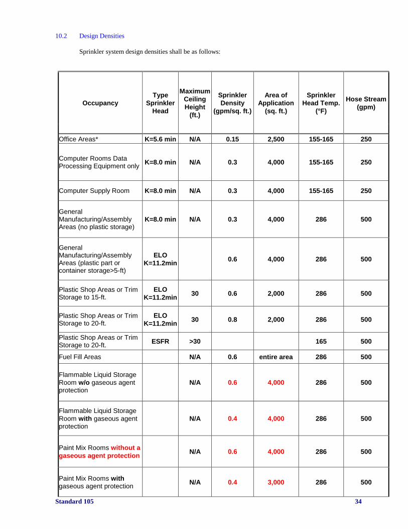
10.2 Design Densities
Sprinkler system design densities shall be as follows:
Occupancy
Type
Sprinkler
Head
Maximum
Ceiling
Height
(ft.)
Sprinkler
Density
(gpm/sq. ft.)
Area of
Application
(sq. ft.)
Sprinkler
Head Temp.
(°F)
Hose Stream
(gpm)
Office Areas* K=5.6 min N/A 0.15 2,500 155-165 250
Computer Rooms Data Processing Equipment only
K=8.0 min N/A 0.3 4,000 155-165 250
Computer Supply Room K=8.0 min N/A 0.3 4,000 155-165 250
General Manufacturing/Assembly Areas (no plastic storage)
K=8.0 min N/A 0.3 4,000 286 500
General Manufacturing/Assembly Areas (plastic part or container storage>5-ft)
ELO
K=11.2min 0.6 4,000 286 500
Plastic Shop Areas or Trim Storage to 15-ft.
ELO
K=11.2min 30 0.6 2,000 286 500
Plastic Shop Areas or Trim Storage to 20-ft.
ELO
K=11.2min 30 0.8 2,000 286 500
Plastic Shop Areas or Trim Storage to 20-ft.
ESFR >30 165 500
Fuel Fill Areas N/A 0.6 entire area 286 500
Flammable Liquid Storage
Room w/o gaseous agent protection
N/A 0.6 4,000 286 500
Flammable Liquid Storage
Room with gaseous agent protection
N/A 0.4 4,000 286 500
Paint Mix Rooms without a
gaseous agent protection N/A 0.6 4,000 286 500
Paint Mix Rooms with gaseous agent protection
N/A 0.4 3,000 286 500
Standard 105 35
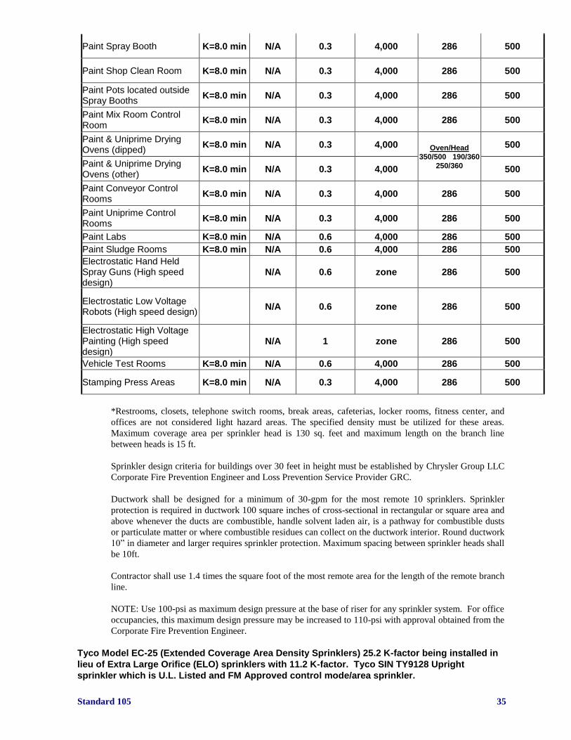
Paint Spray Booth K=8.0 min N/A 0.3 4,000 286 500
Paint Shop Clean Room K=8.0 min N/A 0.3 4,000 286 500
Paint Pots located outside Spray Booths
K=8.0 min N/A 0.3 4,000 286 500
Paint Mix Room Control Room
K=8.0 min N/A 0.3 4,000 286 500
Paint & Uniprime Drying Ovens (dipped)
K=8.0 min N/A 0.3 4,000 Oven/Head
350/500 190/360
250/360
500
Paint & Uniprime Drying Ovens (other)
K=8.0 min N/A 0.3 4,000 500
Paint Conveyor Control Rooms
K=8.0 min N/A 0.3 4,000 286 500
Paint Uniprime Control Rooms
K=8.0 min N/A 0.3 4,000 286 500
Paint Labs K=8.0 min N/A 0.6 4,000 286 500
Paint Sludge Rooms K=8.0 min N/A 0.6 4,000 286 500
Electrostatic Hand Held Spray Guns (High speed design)
N/A 0.6 zone 286 500
Electrostatic Low Voltage Robots (High speed design)
N/A 0.6 zone 286 500
Electrostatic High Voltage Painting (High speed design)
N/A 1 zone 286 500
Vehicle Test Rooms K=8.0 min N/A 0.6 4,000 286 500
Stamping Press Areas K=8.0 min N/A 0.3 4,000 286 500
*Restrooms, closets, telephone switch rooms, break areas, cafeterias, locker rooms, fitness center, and
offices are not considered light hazard areas. The specified density must be utilized for these areas.
Maximum coverage area per sprinkler head is 130 sq. feet and maximum length on the branch line
between heads is 15 ft.
Sprinkler design criteria for buildings over 30 feet in height must be established by Chrysler Group LLC
Corporate Fire Prevention Engineer and Loss Prevention Service Provider GRC.
Ductwork shall be designed for a minimum of 30-gpm for the most remote 10 sprinklers. Sprinkler
protection is required in ductwork 100 square inches of cross-sectional in rectangular or square area and
above whenever the ducts are combustible, handle solvent laden air, is a pathway for combustible dusts
or particulate matter or where combustible residues can collect on the ductwork interior. Round ductwork
10” in diameter and larger requires sprinkler protection. Maximum spacing between sprinkler heads shall
be 10ft.
Contractor shall use 1.4 times the square foot of the most remote area for the length of the remote branch
line.
NOTE: Use 100-psi as maximum design pressure at the base of riser for any sprinkler system. For office
occupancies, this maximum design pressure may be increased to 110-psi with approval obtained from the
Corporate Fire Prevention Engineer.
Tyco Model EC-25 (Extended Coverage Area Density Sprinklers) 25.2 K-factor being installed in
lieu of Extra Large Orifice (ELO) sprinklers with 11.2 K-factor. Tyco SIN TY9128 Upright
sprinkler which is U.L. Listed and FM Approved control mode/area sprinkler.

Standard 105 36
This is acceptable based upon:
a). Design criteria shall remain as 0.80-gpm per square foot over most remote 2,000 square feet plus
500-gpm hose stream allowance.
b). Additionally the design criteria shall be proven to ensure systems can deliver 1.0-gpm per square
foot over the most remote four sprinklers within a minimum end head pressure of 25-psi for this criteria.
c). Sprinkler spacing shall be limited to maximum 150 square feet per sprinkler and minimum 100
square feet per sprinkler coverage. Layout should be designed to be a square pattern or as close to a
square as possible with maximum distance between sprinklers being 12.5 feet and minimum 10 feet.
d). Design calculations for remote area shall use the 1.4 shaping design for number of heads flowing in
remote area.
e). Use 165°F or 212°F (temperature) rated sprinklers.
f). Installation must be in accordance with manufacturer's listing requirements and NFPA #13 including
all obstruction rules (including pipe shadow) but pipe hangers shall meet ME pipe hanger standard.
g). There must be a minimum three foot ceiling level partition between systems using EC-25 sprinklers
and adjacent sprinkler systems that do not have EC-25 sprinklers i.e., standard response sprinklers.
h). Storage of exposed plastic components and containers shall be limited to 20 feet in a 35 foot
building. Any storage racks shall be open frame with wire mesh shelves or no shelves. Solid and
slatted shelves are not accepted unless in-rack sprinklers are installed.
i). Only SSU model sprinklers are approved and shall be used.
j). Clearance from sprinkler deflector to roof deck shall not exceed twelve inches for unobstructed
construction.
Any deviation from the above must be discussed with GRC and Corporate.
NOTE: Sprinkler protection can be omitted from Paint Drying Ovens if they meet certain criteria. This
criteria includes:
Non-crimped (welded) seams
Plastic parts on vehicles limited to gas cap (cover)
No combustible tape, paper, or plastic sheeting on vehicles
In-direct fired burner unit
- Combustion safeguards approved by FM
10.3 Sprinkler Heads (see table)
Sprinkler head type (upright or pendent) should be determined in conjunction with the room design
parameters.
Early Suppression/Fast response (ESFR) sprinklers are becoming a widely used concept in moderate and
high hazard environments and are acceptable for use within Chrysler Group LLC facilities/buildings.
ESFR sprinklers have an extra large orifice and deflector and are designed to produce larger water drops
that quickly pierce a rapidly developing fire, particularly rack storage facilities. ESFR sprinklers also
have a sensitive fusible element that provides fast response to heat. Installations involving ESFR
sprinklers must follow the guidelines within Factory Mutual Data Sheet 2-2 and NFPA #13, latest
editions.
Guidelines for ESFR sprinkler applications shall be found in the latest version of FM Global Data Sheet
2-2 and NFPA #13, latest editions. General guidelines shall be as follows:
Building height - 40 feet or less (roof slope with maximum 2 inches per foot)
Storage height - 35 feet or less
Type of Storage - Rack or Pallets
Not allowed with occupancies involving hydraulic oil under pressure
Chrysler Security Services and GRC shall be consulted before specifying the use of ESFR sprinklers
Standard 105 37
NOTE: There is now an ESFR sprinkler with a K-factor of 25. Presently it is not approved for the
storage of exposed, unexpanded nor expanded plastic storage.
FM Global and NFPA have cancelled as of May 2001 the 45 foot allowance for K-14 and K-16.8 ESFR
sprinklers. They will no longer permit the use of K-14 and K-16.8 ESFR sprinklers for palletized storage
up to 35 feet under a ceiling/roof height up to 45 feet. They will now require one level of in-rack
sprinklers to protect the above storage scenario.
Sidewall sprinkler heads shall not be considered for use in accordance with this Standard.
Sprinklers can be concealed, semi-recessed, or surface mounted design for finished ceiling areas. For
unfinished ceiling areas, sprinklers are exposed in the pendent or up-right position.
FM Global approved Extra Large Orifice (ELO) can be used in lieu of standard orifice sprinkler heads if
approved by GRC. ELO sprinklers are not the same as neither Large Drop nor ESFR sprinklers. ELO
sprinklers have the same nominal K-factor as Large Drop sprinklers but they are not the same and can not
be interchanged.
Before Large Drop sprinklers are recommended, an analysis is required to ensure the model and
manufacturer are approved for the specific application.
All sprinklers that are susceptible to being coated with paint or other foreign materials shall be protected
by an approved method.
Bags over sprinklers - 0.003-inch (0.076 mm) cellophane secured with a rubber band or zip tie.
Sprinkler heads shall be covered with protective cellophane bags (available from Corporate).
Bags shall be attached to the sprinkler head base using zip ties or rubber bands. Zip ties and rubber bands
shall be placed so that they do not interfere with the sprinkler head discharge. Tape is not an acceptable
method for securing the bags.
OR
Wax/lead coated (normally used in corrosive atmospheres)
10.4 Special Requirements
Sprinklers shall be provided in each of the following areas and shall comply with minimum sprinkler
system design criteria:
- Below grated mezzanines
- Below open mesh (employee protection) grating with combustible storage below grating
- Below ducts in excess of 48-inches in width
- Under accessible stairs
- In janitor closets
- In rest rooms
- In plant offices
- In electrical rooms with oil-filled transformers or other combustibles
- At top of elevator shafts
- Exhaust ducts 10 inches in diameter and above for paint spraying operations except for
incinerator / RTO exhaust stacks, mist collectors/sprinklers are required where combustible
residue or solvent laden air is present.
- Under cribbing where the roof of the cribbed enclosure is obstructed from ceiling sprinklers
- Sprinkler control sub valves and water flow switches shall be provided for systems 20 heads or
more.
NOTE: Sprinklers are not required below open mesh grating installed above aisles or within approved
plastic paint tunnels (6 mil unreinforced Visqueen) unless required by AHJ.
There shall be no manifolding of sprinkler risers without the written consent of Corporate and GRC
Standard 105 38
The installing contractor shall identify a hydraulically designed sprinkler system with a permanently
marked weatherproof metal or rigid plastic sign secured with corrosion-resistant wire, chain, or other
approved means. Such signs shall be placed at the alarm valve, dry pipe valve, pre-action valve, or
deluge valve supplying the corresponding hydraulically designed area.
Sprinkler system identification numbering sequence shall be obtained from the local fire responsible
person. This sequence is for PIV’s, SCV’s, hydrants, risers, sub valves, and hose drops. This numbering
system will be used in the plant fire alarm descriptor points.
High Volume Low Speed (HVLS) Fans. The installation of HVLS fans in buildings equipped with
sprinklers, including ESFR sprinklers, shall comply with the following:
(1) The maximum fan diameter shall be 24 ft.
(2) The HVLS fan shall be centered approximately between four adjacent sprinklers.
(3) The vertical clearance from the HVLS fan to sprinkler deflector shall be a minimum of 3 ft.
(4) All HVLS fans shall be interlocked to shut down immediately upon receiving a water flow signal
from the alarm system in accordance with the requirements of NFPA 72.
10.4.1 Cross Ties
Sprinkler system cross ties are not required in any Chrysler Group LLC facility for new
construction.
10.4.2 Guard Posts
All risers, PIV, SCV, Wall valves and hydrants shall be guarded if they are subject to damage by traffic.
See ME “Standard Details” for guard post design requirements. These guard posts shall not obstruct the
discharge butts from the fire hydrants and allow for a sprinkler control valve or sectional control valve to
be closed with a wrench.
Standard 105 39
11.0 Standpipes and Hose Stations
11.1 General
NFPA No. 13, 2007 edition does not require 1.5-inch fire hose drops or hose stations if approved by
local AHJ. If fire hose drops are required by local AHJ, fire hose control valves (1.5”) must have built-in
pressure limiting device that limits pressure to 80-psi. Pressure limiting disks shall not be used as a
method to reduce pressure.
When required, standpipes and hoses stations shall have a 2½-inch supply pipe and outlet. They can
have a 1½-inch supply pipe and outlet instead of a 2½-inch supply pipe and outlet if the standpipe serves
a sprinkled building.
Required standpipes in stairwells of multi-story buildings shall have 2½-inch outlets.
Fire hose stations can be provided with a 2½-inch to 1½-inch reducer outlet in stairwells if hose is
incorporated with the standpipe system.
No fire hose stations should be installed within 20 feet of a penthouse door opening if it is possible for
the outdoor temperature to drop below 40°F.
When required, fire hose stations shall be designed in accordance with the latest editions of NFPA #13,
“Installation of Sprinkler Systems” and NFPA #14, “Installation of Standpipe and Hose Systems”.
Fire hose stations shall be spaced such that 100 feet of hose plus 30 feet of nozzle range can be reached
by all portions of the area protected by a fire hose station.
Pressure reducing angle valve (chrome plated or brass) shall be used where water pressure
exceeds 80 PSI at the valve outlet. No valves using pressure limiting disks shall be used.
Cabinet type and equipment for fire hose stations shall be specified by Corporate.
11.2 Classifications
Standpipe and fire hose systems have three classifications, based on intended use, as follows:
Class I for use by fire department and those trained in handling heavy fire streams.
- Standpipes for Class I service shall be provided with 2½-inch hose connections.
Class II for use by building occupants.
- Standpipes for Class II service shall be provided with 1½-inch hose connections and fire hose.
Class III for use by either fire department or building occupants.
- Standpipes for Class III service shall be provided with both a 2½ inch and a 1½ inch hose
connection (reducer outlet) and fire hose.
11.3 Cabinets
Fire hose cabinets shall be provided in finished (office) areas of all buildings.
Fire hose cabinets shall be of the surface mounted or recessed type.
Fire hose cabinets containing fire hose and an extinguisher shall have the following equipment:
- Angle Valve (chrome plated) with a 2½-inch to 1½-inch reducer
Standard 105 40
- Pressure reducing angle valve (chrome plated or brass) where water pressure exceeds 80 PSI at
the valve outlet (if required by hydraulic calculations).
- Fire hose racks inside the cabinet shall be of the semi-automatic type, suitable for nipple
mounting. Rack finish shall be of chrome plated steel or manufacturer’s standards.
Fire hose shall be U.L. listed and/or FM approved; 1½-inch, 50-foot lengths, lightweight, single ply
thermoplastic lined.
Fire hose nozzles shall be of the adjustable fog type and suitable for Class A and B fires. Nozzles shall be
threaded to match facility and/or fire department threads, and shall be adjustable to “off” and “straight”
stream patterns. Nozzles shall be of the twist type Lexan material, fog nozzle.
Fire extinguishers, when provided, shall be of a type suitable to the hazard being protected.
Cabinets shall be designed for hose valves, fire hose and one fire extinguisher.
11.4 Reels/Racks
Wall mounted hose racks (usually in cabinets) are used in office buildings.
Fire hose holder shall be used in manufacturing area’s where possible.
Fire hose holder covers shall be of vinyl coated fabric, fire-orange color, and shall be flame resistant and
impervious to oil and grease.
Fire hose reels 26 inch if used shall be constructed off seamless steel tube with plate rims and yokes, red
enamel spokes and cast hubs.
Fire hose reels covers shall be of vinyl coated fabric, fire-orange color, and shall be flame resistant and
impervious to oil and grease.
11.5 Fire Hose
Fire hose is typically required for buildings as part of the standpipe and hose system. Fire hose is
mounted on racks fire hose cabinets, rolled in fire hose holders or rolled on fire hose reels.
Two types of hose are required:
The only approved hose will be as follows:
11.5.1 Light Duty Hose
Light duty fire hose Chrysler Group LLC number 78-085-1750 shall be used on standpipe hose racks in
office buildings and similar locations. This hose shall not be used where “hard” service, high pressure,
or difficult storage conditions will be encountered.
Single Jacket Length Test (PSI) Size (I.D.) NPM
44-RR-55 50 500 1½-inch 78-085-1750
Fire hose shall be National Fire Hose Div of Snap-Tite Hose Inc. U.L. listed and/or FM approved, two-
50 foot lengths per hose rack, 100% synthetic woven jacket, single ply thermoplastic lining.
11.5.2 Heavy Duty Hose
Heavy-duty fire hose Chrysler Group LLC number 78-085-1751 shall be used on standpipe hose
reels/racks in powerhouses, manufacturing, warehouses, machining, assembly and other building
buildings where heat, corrosive atmospheres, moisture and high water pressure or surge may be
encountered.
Standard 105 41
Single Jacket Length Test (PSI) Size (I.D.) NPM
44-AP3 50 300 1½-inch 78-085-1751
Fire hose shall be National Fire Hose Div of Snap-Tite Hose Inc. U.L. listed and/or FM approved, two-
50 foot lengths per hose rack, 100% polyester woven jacket, single ply extruded synthetic rubber.
11.6 Nozzles
Nozzles shall be of the twist type, on off, fog type and shall be of Lexan plastic.
Standard 105 42
12.0 Fire Extinguishers
12.1 General
Fire extinguishers shall be provided for all building areas including the offices, data processing and
warehouse.
12.2 Types
Class ‘A’ rated fire extinguishers, water or dry chemical, shall be installed in all areas such that a travel
distance of no more than 75 feet is required to reach a unit. Dry chemical units shall not be used around
computer equipment or in Paint Shops.
12.3 Size of Units
The sizes (ratings), manufacturer and distribution of the units shall be directed by Corporate. No 2-1/2 #
or 5 # units shall be used in Chrysler Group LLC facilities.
15# carbon dioxide and 20 # ABC dry chemical units are to be used for Chrysler Group LLC facilities.
Standard 105 43
13.0 Painting and Labeling of Fire Protection Equipment
13.1 General
Chrysler Group LLC Manufacturing Technical Instruction SMI-111 (issue date 6-1-92) shall be used for
the identification of pipe systems. All building columns shall be labeled as to bay and column number per
the ME standards.
13.2 Fire Quenching Materials
This classification of piping includes sprinkler systems and other piped fire fighting or fire protection
equipment. Included is water, chemical foam, carbon dioxide systems, HFC-227ea (FM-200) systems,
HFC-125 (ECARO), Pro-inert, etc.
13.3 Fire Protection Systems
Fire protection system piping shall be painted red per Spec. #NPVP 7.5R and NP Code No. 65-150-6090
“Safety Red” from floor to truss. Directional arrows are required on risers and feed mains. Each fire
system sprinkler riser shall be identified with a sign attached to the base of the riser showing the riser
number. Additionally, one sign shall be attached (by chains) to the upper section of the riser and four (4)
signs similarly attached randomly from the riser feed/branch lines. On multiple level buildings four (4)
signs are needed for each level. Additional signage is required on either side, whenever the lines
penetrate a floor or wall. All inspector test lines and hose drops shall be labeled as to the corresponding
automatic sprinkler riser. The labeling shall be 1-inch lettering and read:
“RISER (number)”.
Any riser that has an interlock associated with the water flow shall be provided with a identification sign
(FD7546-1)
13.4 Hydrants
Chrysler Group LLC (private) fire hydrants shall be painted red.
Hydrants shall be numbered using 2-inch high white numbers.
City fire hydrants shall be painted per city code requirements.
13.5 Post Indicator Valves (PIV)
PIV’s shall be painted red with 2-inch high white numbers.
13.6 Sectional Control Valves
SCV’s shall be painted red with white caps. SCV’s shall be lettered with 2 inch white letters.

Standard 105 44
14.0 Specific Occupancy Requirements
14.1 Training
Local G4S Secure Solutions (G4S) Plant Security shall be provided with 3 – 8 hour training classes on
all special fire suppression and fire alarm systems installed as a result of this Standard. The installing
Contractor shall also provide instruction manuals to all participants. The training course shall be
reviewed by Corporate for content.
14.1.1 Gaseous Agent Release control panel
All gaseous agent release control panels shall be located outside of the protected space. Bypass switches
shall be located inside the lockable enclosure. The Fike Cheetah Xi panel or Detector Electronics Eagle
Quantum Premier Systems shall be the only control panels used for new installations.
14.2 Flammable Liquid Storage Rooms
14.2.1 Construction
Distance or construction shall isolate flammable liquids so that a fire cannot spread to or from the storage
room. Storage rooms shall be of fire resistant or non-combustible construction and shall be rated for
three hours. The room shall have sufficient mechanical ventilation to prevent flammable vapor
concentrations from reaching explosive limits (explosive range).
Flammable liquid storage rooms shall not be located below grade. However, the floor slab may be
depressed to provide spill containment. Doorways shall have ramps or curbs at least 4 inches high to
contain a spill from 150% of the largest container plus minimum 10 minutes of sprinkler water discharge.
Doors shall be self-closing and rated to maintain the intended fire resistance rating of the barrier.
Penetrations of barrier walls shall be sealed to maintain the intended fire resistance rating of the barrier.
14.2.2 Fire Protection
Fire suppression for flammable liquid storage rooms shall consist of sprinklers and HFC-227ea (FM-200)
or HFC-125 (ECARO), or Pro-inert protection (main cylinder bank only) or sprinklers with AFFF
injection.
Sprinkler design density for sprinklers and HFC-227ea (FM-200) or HFC-125 (ECARO), or Pro-inert protection shall be 0.60 GPM per square foot for the most remote 4,000 square feet.
Sprinkler design density for sprinklers with AFFF injection shall be 0.40 GPM per square foot for the
most remote 3,000 square feet.
AFFF injection shall be operable for 10 minutes, with an additional 10 minutes reserve concentrate
supply available within the AFFF tank. Adding 10-minute supplies, plus initial inside fire hose demand
for the flammable liquid storage room shall be used to calculate water supply. Also, include any in-rack
sprinkler demand plus other fire hose demand.
Additional sprinkler protection shall be provided under all elevated tote storage racks or platforms.
Roller platforms shall be stored a maximum of three tiers high. Drums or pallets shall be stored a
maximum of one high.
All dispensing equipment shall be of the drum pump or “dead” person type, and shall be electrically
grounded per the latest edition of NFPA #77, “Static Electricity”.

Standard 105 45
Curbs and trenches shall be provided to contain and remove flammable liquid spills in accordance with
applicable codes.
All electrical components and wiring shall meet the hazardous location requirements in the latest edition
of NFPA #70, “National Electrical Code”.
Traps shall be provided for drains, with deep seal traps if HFC-227ea (FM200) , HFC-125 (ECARO) or
Pro-inert, is used, to contain the suppression agent.
14.3 Paint Mix Room
14.3.1 Construction
Distance or construction shall isolate paint mix rooms so that fire cannot spread to or from the paint mix
room. Mix rooms shall be of fire resistant or non-combustible construction and shall be rated for three
hours fire resistance. The room shall have a minimum of 1-cfm/square foot of continuous low-level
mechanical ventilation to prevent flammable vapors from reaching explosive limits (explosive
range)(minimum of 150 cfm).
Paint mix rooms shall not be located below grade. Provide at least a 4-inch curb or ramp at all doors to
contain a spill from 150% of the largest container plus minimum 10-minute discharge from sprinkler
system.
Doors shall be self-closing and rated to maintain the intended fire resistance rating of the barrier.
Penetrations of barrier walls shall be sealed to maintain the intended fire resistance rating of the barrier.
Vapor removal shall be incorporated into the paint mix room design. No drainage piping shall be buried
below mix or storage room floors. All drainage from the paint mix room shall be conducted to the edge
of the room in trenches with grating covers.
14.3.2 Fire Protection
Fire suppression for paint mix rooms shall consist of sprinkler and HFC-227ea (FM-200), HFC-125
(ECARO) or Pro-inert, protection (main cylinder bank only) or sprinklers with AFFF injection.
Sprinkler design density for sprinklers and HFC-227ea (FM-200), HFC-125 (ECARO), or Pro-inert
protection shall be 0.60 GPM per square foot for the most remote 4,000 square feet.
Sprinkler design density for sprinklers with AFFF injection shall be 0.40 GPM per square foot for the
most remote 3,000 square feet.
AFFF injection shall be operable for 10 minutes, with an additional 10 minutes reserve concentrate
supply available within the AFFF tank. Adding 10-minute supply, plus initial inside fire hose demand for
the paint mix room shall calculate water supply.
Additional sprinkler protection shall be provided under all elevated tote racks.
Sprinkler heads shall be of the fusible link type and shall have a 286°F temperature rating.
Multiple level “rate-of-rise” detectors or IR3 detectors are approved for paint mix rooms.
All equipment in paint mix rooms shall be electrically grounded per the latest edition of NFPA #77,
“Static Electricity”.
All electrical components and wiring shall meet the hazardous location requirements in the latest edition
of NFPA #70, “National Electrical Code”.
Material handling equipment, including lift trucks, shall be classified as EE or DY lift trucks.
Standard 105 46
There shall be at least two remote means of egress from the room.
14.3.2.1 Carbon Dioxide Protection
Carbon Dioxide Fire Protection System Minimum Requirements
Scope:
This section contains minimum requirements for carbon dioxide fire protection systems. It includes only
the basic essentials to make the standard workable in the hands of those trained & skilled in this field.
Only those with the proper training and experience shall design, install, inspect, and maintain this
equipment. Examples of proper training would be factory certification by a particular system
manufacturer.
The entire system shall comply with the most current edition of NFPA #12 and this Standard.
Systems:
Two major types of carbon dioxide systems are used at Chrysler Group LLC facilities – Total Flooding
systems and Local Application systems.
Total Flooding System – consists of a fixed supply of carbon dioxide normally connected to fixed piping
with nozzles arranged to discharge carbon dioxide into an enclosed space or enclosed space around the
hazard.
Local Application System - consists of a fixed supply of carbon dioxide normally connected to fixed
piping with nozzles arranged to discharge carbon dioxide directly on the burning materials.
Agent Storage Containers:
Carbon dioxide extinguishing systems use either high-pressure storage units (cylinders at room
temperature usually in 75 or 100 lb. capacity for industrial applications) or low pressure storage units
(large refrigerated tanks – ¾ ton or larger). Ansul’s Mini-bulk low-pressure system range from 500-lb. to
1,500-lb. Capacity and are considered low- pressure systems.
System storage container selection is primarily based upon economics that is strongly influenced by
hardware requirements. Typically, selecting a low-pressure storage container becomes more favorable as
system carbon dioxide requirement increase. Multiple timed discharges are also possible with low-
pressure storage containers.
High Pressure – Indicates that the carbon dioxide is stored in pressure containers at atmospheric
temperatures. At 70 F, the pressure in this type storage is 850 psi.
Low Pressure - Indicates that the carbon dioxide is stored in pressure containers at controlled
temperatures, at 0 F. At 0 F, the pressure in this type storage is 300 psi.
Extinguishing Mechanism:
Carbon dioxide extinguishes a fire by oxygen depletion and reducing the oxygen content from the normal
21% in air to 15%. This will extinguish most fires. The cooling effect created by a carbon dioxide
discharge is of little significance. Since it is a gas, it will penetrate and spread to all parts of a hazard.
Carbon dioxide does have a density about 50% greater than the density of air.

Standard 105 47
Applications:
Based upon Chrysler Group LLC Corporate Standards, carbon dioxide shall not be a replacement for
providing automatic sprinkler protection, unless approved by the Chrysler Group LLC Corporate Fire
Prevention engineer. A carbon dioxide fire suppression system can be used to provide supplemental fire
protection in the following areas:
Within machine enclosures, associated ductwork and oil mist collector(s) using combustible cutting
oil.
NOTE: Carbon dioxide protection can be omitted within horizontal ductwork and oil mist collector if all
three of the following conditions are met and approved by local AHJ:
1). There is a damper on all vertical ductwork interlocked to close automatically prior to discharge of the
carbon dioxide system.
2). All horizontal ductwork and oil mist collector(s) have automatic sprinkler protection. Also, the
ductwork must be designed to hold the additional weight of the sprinkler water discharge.
3). Carbon dioxide system is designed to protect the entire machine enclosure and vertical ductwork.
Within unmanned pits such as caster/camber, roll test, BSR pits, etc. (if manned pits, HFC-227ea
(FM-200) shall be used)
Within normally unmanned rooms, if approved by the Corporate Fire Prevention engineer. An
example is a dynamometer test cell.
Beneath raised floor of a data/computer room(s).
Heat-treat operations using combustible quench oil (local application).
Sequence of Operation using fixed temperature heat detectors:
Rooms (dynamometer, engine test, etc.):
Minimum two detectors
Activation of alarms within room, outside room and on Release control panel upon activation of 1st
detector.
Activation of all interlocks upon activation of 1st detector.
Discharge of carbon dioxide gas after a 30 second pneumatic time delay upon activation of 1st
detector.
Pneumatic siren or sirens
NOTE: Pneumatic time delay not required on systems protecting high hazard fires such as flammable
liquids.
Machinery Enclosure when protected is required:
Minimum two detectors
Activation of alarms on equipment and release control panel upon activation of 1st detector.
Activation of all interlocks upon activation of 2nd
detector.
Discharge of carbon dioxide gas upon activation of 2nd
detector with no time delay.
NOTE: Sequence of Operation for each protected machinery enclosures must be reviewed on a case-by-
case basis due to various factors that may apply. It is critical that contractor contact Chrysler Group LLC
Corporate Fire Prevention Engineer and GRC prior to engineering the protection so that any factors can
be reviewed prior to designing the protection.
Hazards to Personnel (Also refer to latest edition of NFPA #12):
The discharge of carbon dioxide in fire-extinguishing concentration creates serious hazards to personnel,
such as suffocation and reduced visibility during and after the discharge period. In any use of carbon
dioxide, consideration shall be given to the possibility that personnel could be trapped in or enter into an
atmosphere made hazardous by a carbon dioxide discharge. In addition to the protected space,
consideration shall also be given to the possibility of carbon dioxide drifting and settling into adjacent
places outside of the protected space. Consideration shall also be given to cylinder storage areas where
the carbon dioxide can collect in the event of a discharge from a safety relief device of a storage
container. Suitable safeguards shall be provided to ensure prompt evacuation, to prevent entry into such
Standard 105 48
atmospheres, and to provide means for prompt rescue of any trapped personnel. Personnel training shall
be provided. Pre-discharge alarms shall be provided in all cases unless specifically waived in
writing by Corporate Fire Prevention and GRC and other authorities having jurisdiction.
To prevent accidental or deliberate discharge, a supervised “lock-out” valve as defined in NFPA
#12 shall be provided when persons not familiar with the systems and their operation are present
in a protected space. This lock out valve shall be specifically addressed in the release control panel
and report an individual point from the release panel to the plant alarm system in the form of a
dry contact. Any employee or vendor representative shall notify Plant Security before inspecting,
modifying, and/or servicing any carbon dioxide system or systems. Lockouts that utilize software
only are not acceptable/permitted. Pneumatic time delay (in most cases) and pneumatic siren are
required.
Local application systems shall be locked out when persons are present in locations where
discharge of the system will endanger them, and they will be unable to proceed to a safe location
within the time-delay period for the system. When protection is to be maintained during the
“lockout” period, a person(s) shall be assigned as a “fire watch” with suitable portable fire-
fighting equipment or means to restore protection. The fire watch shall have a communication link
to a constantly monitored location. Authorities responsible for continuity of fire protection shall be
notified of lockout (and will lock the system) and subsequent restoration of the system.
Plans & Approvals
Plans and calculations shall be submitted and approved by the local Authority Having Jurisdiction (AHJ),
Global Risk Consultants (GRC) and other agencies as required by Corporate before beginning the
installation. Plans and calculations shall be prepared by person(s) certified/qualified in the design of
carbon dioxide fire-extinguishing systems.
Plan submittal to GRC shall include:
CO2 Requirements
Plans must contain sufficient detail to enable the reviewers to evaluate the hazard or hazards and to
evaluate the effectiveness of the system. The details shall include the following:
(1) Materials/Operation involved in the protected hazards/area. Include type of fuel and how stored
and/or dispensed.
(2) Location of the hazard or hazards, i.e., Bay/Column, floor level, basement, pit, etc.
(3) Enclosure (isolation) or limits of the hazard(s).
(4) Surrounding areas that could affect the protected hazard(s).
(5) Information and calculations on the amount, time of discharge and concentration of carbon
dioxide.
(6) Location and flow rate of each nozzle including equivalent the orifice area.
(7) Location, size, and equivalent lengths of pipe, fittings, and hose.
(8) Location and size of the carbon dioxide storage facility.
(9) Known areas other then the protected hazard where CO2 may accumulate during or after a
discharge.
(10) Provisions present for removing carbon dioxide after a discharge.
(11) Hanger details for piping.
(12) Recharge capabilities of the installing contractor.
(13) Other items required per the latest edition of NFPA #12.
Standard 105 49
Control System Requirements for all gaseous agents:
1. All control equipment must be UL listed and/or FM approved and located outside the protected area.
2. The release control panel & all devices must be pre-approved by the Chrysler Group LLC Corporate Fire
Prevention engineer prior to preparation of the system proposal. Only approved intelligent,
addressable release control panels with an event history memory buffer shall be quoted and
installed. For an existing facility, the release control panel and associated equipment shall match
the existing manufacturer of other gas agent systems, or be pre-approved by the Chrysler Group
LLC Corporate Fire Prevention Engineer. The release control panel must be compatible and
approved for use with all associated equipment. A single hazard panel may be utilized with the
concurrence of the Corporate Fire Engineer.
3. The release control panel must be housed in a red painted NEMA-12 enclosure and contain separate
keyed bypass switches for AC power, battery power, system interlocks, extinguishing agent circuit, and
detector power circuit.
4. Each switch and all initiating devices connected to the release control panel shall be separately
addressed. NOTE: Each release control panel shall be connected/monitored at the Plant’s Proprietary
Alarm system and designed to activate an alarm upon discharge of the carbon dioxide.
5. Automatic operation of the suppression system shall be by a minimum of two sensors regardless of the
size of the hazard, unless written authorization is obtained from the Chrysler Group LLC Corporate Fire
Prevention Engineer.
6. Where personnel may be located inside/within a protected area (volume), all total-flooding systems shall
have a pneumatic time delay (30 seconds minimum) & pneumatic siren. Notification appliances shall
meet the requirements of NFPA 12. NOTE: Pneumatic time delay device might not be required per latest
edition of NFPA #12 for fast acting, high heat release fires such as involving flammable liquids.
7. Separate carbon dioxide systems, including Release control panels, shall be provided for each hazard. A
selector valve(s) for multiple hazards may be quoted as an alternative. Any system utilizing a selector
valve system shall have a main & reserve bank (two shots) of carbon dioxide, unless the carbon dioxide
agent can be re-filled within 8 hours.
8. Manual release stations shall be dual-action style that requires the opening of a hinged cover and
operation of a lever to initiate a manual discharge.
9. Unless pre-approved by the Chrysler Group LLC Corporate Fire Prevention Engineer, each manual
release station shall have two addresses so that failure of a single addressable module in an alarm mode
will not initiate a discharge. Failure of a single module in an alarm mode will result in a specific (trouble)
indication at the release control panel.
10. Care shall be taken during the design process to insure systems are arranged to discharge simultaneously
where hazards are connected by common exhaust systems, flumes, etc. or where hazards are located
close enough for fire to potentially spread between hazards. The Chrysler Group LLC Corporate Fire
Prevention Engineer shall make the decision when two or more adjacent hazards will be protected as one
hazard as noted in the latest edition of NFPA #12.
11. A wintergreen scent shall be added to the carbon dioxide.
12. Any switches associated with the release panel shall be located within a locked NEMA enclosure. The
NEMA cabinet shall be locked Lock NPN code 35-610-0864
13. Switches shall include AC power, DC power, interlocks, detectors, and agent. If a purge fan is included
with the system then the switch is also located in the enclosure cabinet.
14. Signage will be provided for interlocks (FD7546-2)
Design Criteria:
Minimum design concentration shall be 34% for all occupancies involving flammable liquids and
discharge time shall be as specified within the latest edition of NFPA #12. Ductwork protection shall be
calculated at a minimum 65% concentration with no specific hold-time, however, a concentration of at
least 34% achieved during an acceptance test would be considered acceptable, if allowed by the local
AHJ.
Location of carbon dioxide cylinders and release control panel shall not be within the protected pit or
pits.
A hazard protected by automatic sprinklers with carbon dioxide as supplemental protection, shall require
only a main supply. If a carbon dioxide system protects multiple hazards, an amount of carbon dioxide
sufficient for (at least) the largest single hazard of the group shall be provided.
Standard 105 50
The bidding Contractor(s) are responsible to determine if relief venting is required. The cost to provide
this venting shall be included in the Contractor’s bid. The Contractor shall ensure the venting discharges
to a safe location.
Carbon Dioxide Concentration Discharge Test:
For a total flooding system protecting a room enclosure, a full carbon dioxide discharge test shall be
conducted to test the integrity of the enclosure and ensure that the design concentration is attained within
the specified time limit as specified in the latest edition of NFPA #12. Tests shall be conducted until
room passes the particular test. Cost to recharge cylinders shall be included in price. NOTE: No hold
time required for surface fires.
Contractor shall pre-determine who is responsible for the integrity of the room (and necessary venting, if
required) before the test. This may require a door fan test to prove the integrity of the room.
Refer to Acceptance Test/Maintenance Requirements section below for additional details.
Pre-discharge Warning:
Warning shall include audio and visual signals within the protected room and outside any door opening.
These devices must be able to operate on primary and backup power supplies.
Pre-acceptance Tests:
Contractor shall conduct full function electrical test of all devices and conduct a “puff” and pressure test
on the distribution piping.
Acceptance Tests/Maintenance Requirements:
Follow Standard #103 – “Acceptance Testing”. The installation Contractor shall provide a checklist to
be used to ensure all devices are inspected, tested and can be properly signed-off. The test form(s)
(checklist(s)) shall be submitted to Corporate at least 10 days prior to the scheduled test(s) for approval.
A Manufacturer’s test and maintenance procedure shall be provided to the owner for testing and
maintenance of the system. This procedure shall provide for the initial testing of the equipment as well as
for periodic test inspection and maintenance of the system.
Prior to conducting acceptance test(s) for room and machine enclosures, the following shall be
determined:
1). Prior to bidding, determination of the protected hazard height (highest level for sampling) shall be
made.
2). One sampling probe shall be just above the agreed upon protected hazard height.
3). Minimum of three (3) sampling probe locations shall be used. NOTE: Location of the sampling
probes with respect to the discharge nozzles shall be agreed upon prior to conducting the test(s).
Meter not required to be used on local application systems. Concentration test meter shall be used on
total flooding system acceptance tests. Recharge of cylinders required after each test.
Interlocks:
Interlocks shall include the following, as applicable:
Shutdown of electrical power to equipment within hazard (automation shutdown)
Shutdown of ventilation
Closing of dampers
Closing of fire doors
Fuel supply shutoff device
Shutdown of conveyors
Standard 105 51
Other items as they apply to the given hazard/exposure
Note: Interlock modules shall be located within locked enclosure with release control panel and not within
control panel of the protected equipment.
Alarms:
The facility’s proprietary fire alarm panel shall monitor all alarms.
These alarms shall include:
System pre-discharge (alarm). The first alarm will signal the local plant fire alarm system.
System “trouble” signals such as grounded, “short” or “open” circuits.
System supervisory signals such as closing of tamper valve on lockout valve
Proprietary Products*:
a). High Pressure Systems:
1). Ansul
2). Fike
3). Kidde Fire
b). Low Pressure Systems:
1). Ansul
2). Chemetron
* The same manufacture of equipment at a given existing plant shall be utilized for all new protection
systems being installed at the plant.
14.3.3 Ventilation
Ventilation in the paint mix rooms and flammable liquids storage rooms shall be designed to provide 1
cubic foot per minute of low level exhaust per square foot of floor area (1:1). Minimum design is 150
CFM. Suction shall be within 12 inches of the floor. Provide positive means to determine that the
ventilation system is operational such as sail switches, end shaft monitoring etc.
14.3.4. Explosion Relief Venting
Explosion relief venting for the paint mix room shall be provided at a ratio of 1 square foot per 50 cubic
feet of room volume (1:50). Explosion relief venting can be designed into either the roof or wall in
conjunction with building/room design parameters. NOTE: Roof should only be used if necessary and
weather conditions are not a concern in the design.
Explosion relief venting shall relieve at 20-25 pounds per square foot, but in no case less than the design
wind load pressure.
Explosion resistance shall be 100-125 pounds per square foot, but in no case less than five times the vent
release pressure. NOTE: Most projects end up having relief venting panels of 25 pounds per square foot
and 125 pounds per square foot explosion resistance walls.
Standard 105 52
14.4 Computer Room
14.4.1 Construction
Computer rooms shall have a fire resistance rating of at least one-hour, and shall be located adjacent to
non-hazardous processes or operations. Openings in floors or walls shall be sealed to maintain the
intended rating of the barrier.
Interior finish shall be non-combustible.
Raised floors are common with computer rooms to channel equipment cables and to provide ventilation
to the computer room. Carpeting is permitted if it has a flame spread rating of 25 or less.
Mechanical ventilation equipment shutdown is required as part of suppression system actuation. Positive
air pressure is usually the result of mechanical ventilation to the room.
Where possible roof drains, sprinkler supply mains and domestic liquid piping shall be routed around the
computer room enclosure
14.4.2 Fire Protection
Fire suppression for the computer rooms shall consist of sprinklers and HFC-227ea (FM-200), HFC-125
(ECARO) Pro-inert protection (main cylinder bank only).
If only under-floor protection is provided for a computer room, carbon dioxide is acceptable for use in
lieu of HFC-227ea (FM-200) or HFC-125 (ECARO).
Sprinkler design density shall be 0.30 GPM per square foot for the most remote 4,000 square feet.
Maximum coverage per sprinkler head is 100 square feet per head unless room design meets the exact
criteria for using an approved sprinkler with greater coverage per head.
In areas where raised floors are used, under floor spaces shall be protected with HFC-227ea (FM-200) or
HFC-125 (ECARO) in rooms where above floor HFC-227ea (FM-200) , HFC-125 (ECARO), Pro-inert
protection is provided.
An alternative to sprinkler and HFC-227ea (FM-200) or HFC-125 (ECARO) protection is to provide
HFC-227ea (FM-200) , HFC-125 (ECARO), Pro-inert protection in the form of a main and reserve
cylinder system.
This method shall only be utilized after consultation with the Corporation Fire Prevention Engineer.
Equipment shutdown, dampers, door closures and sealing of all penetrations and openings are required
for effective suppression system operation.
Design concentrations:
FM-200 (HFC-227ea) is 6.25% minimum.
ECARO (HFC-125) is 8% minimum.
Pro-inert (IG-55) is 34.2% minimum.
A purge fan is not required by Corporate, but may be requested in consultation with the end user.
When a purge fan is used for the removal of gas and unburned particles of combustion, the fan must be
interlocked so that if the fan is running the gas agent can not be discharged. Control of the switch
controlling the purge system shall be within the gas agent locked release control panel and switch shall be
monitored or other suitable method used to ensure fan can not operate during a gas agent discharge.
Standard 105 53
14.5 Vehicle Test Room
14.5.1 Construction
Distance or construction shall isolate vehicle test rooms so that fire can not spread to or from the rooms.
Rooms shall be of fire resistant or non-combustible construction, and shall be rated for two hours. The
rooms shall have sufficient continuous low level mechanical ventilation to prevent flammable vapors
from reaching explosive limits (explosive range), but not less than one CFM per square foot (150 CFM
minimum).
Vehicle test rooms shall not be located below grade.
Test rooms shall have two means of egress.
A listed spring loaded fusible link valve shall be installed on the fuel supply piping where the fuel supply
line enters the building (interior wall).
Doors shall be self-closing and rated to maintain the intended fire resistance rating of the barrier. Doors
and doorframes located in the explosion resistance walls shall be arranged to withstand an explosion.
Normally the doors are arranged to “push” against the doorframe in the event of an explosion.
Penetrations of barrier walls shall be sealed to maintain the intended fire resistance rating of the barrier.
Chrysler Group LLC document MTI SMI-123 entitled “General Construction – Engine Dynamometer
and Fuel Supply Systems” shall be followed during design and construction of vehicle test rooms.
14.5.2 Fire Protection
Fire suppression for vehicle test rooms shall consist of sprinkler and HFC-227ea (FM-200), HFC-125
(ECARO) or Pro-inert protection (main cylinder bank only).
The fire detection system shall automatically release the gaseous agent with a maximum ten second
delay.
The manual release station shall release the gaseous agent with a maximum ten second delay.
Sprinkler design density shall be 0.60 GPM per square foot for the most remote 4,000 square feet.
All dispensing equipment shall be by drum pump or “dead” man valve and shall be electrically grounded
per NFPA #77, “Static Electricity”.
IR3 infrared detectors are acceptable for use in these areas in place of conventional heat detectors.
Curbs and trenches shall be provided to contain and remove flammable liquid spills in accordance with
applicable codes.
All electrical components and wiring shall meet the hazardous location requirements in the latest edition
of NFPA #70, “National Electrical Code”.
Standard 105 54
14.5.3 Explosion Relief Venting
Explosion relief venting for vehicle test rooms shall be provided at a ratio of 1 square foot per 50 cubic
feet of room volume (1:50). Explosion relief venting can be designed into either the roof or wall in
conjunction with building/room design parameters. NOTE: Roof should only be used if necessary and
weather conditions are not a concern in the design.
Explosion relief venting shall relieve at 20-25 pounds per square foot, but in no case less than the design
wind load pressure.
Explosion resistance shall be 100-125 pounds per square foot, but in no case less than five times the vent
release pressure. NOTE: Most projects end up having relief venting panels of 25 pounds per square foot
and 125 pounds per square foot explosion resistance walls.
14.6 Engine Test Cell
14.6.1 Construction
Distance or construction shall isolate engine test cell rooms so that fire can not spread to or from the
rooms. Rooms shall be of fire resistant or non-combustible construction, and shall be rated for two
hours. The rooms shall have sufficient continuous low level mechanical ventilation to prevent flammable
vapors from reaching explosive limits (explosive range), but not less than one cfm per square foot (150
cfm minimum).
Engine test cell rooms shall not be located below grade.
Test cell rooms shall have two remote means of egress.
A listed spring loaded fusible link valve shall be installed on the fuel supply piping where the fuel supply
line enters the building (interior wall).
Doors shall be self-closing and rated to maintain the intended fire resistance rating of the barrier. Doors
and doorframes located in the explosion resistant walls shall be arranged to with stand an explosion.
Normally the doors are arranged to “push” against the doorframe in the event of an explosion.
Penetrations of barrier walls shall be sealed to maintain the intended fire resistance rating of the barrier.
Chrysler Group LLC document MTI SMI-123 entitled “General Construction – Engine Dynamometer
and Fuel Supply Systems” shall be followed during design and construction of engine test cell rooms.
14.6.2 Fire Protection
Fire suppression for engine test cell rooms shall consist of sprinkler and HFC-227ea (FM-200), HFC-125
(ECARO) or Pro-inert protection (main cylinder bank only). Carbon dioxide is not acceptable.
The fire detection system shall automatically release the gaseous agent with a maximum ten second
delay.
The manual release station shall release the gaseous agent with a maximum ten second delay.
Sprinkler design density shall be 0.60 GPM per square foot for the most remote 4,000 square feet.
All dispensing equipment shall be by drum pump or “dead” man valve and shall be electrically grounded
per the latest edition of NFPA #77, “Static Electricity”.
IR3 infrared detectors are acceptable for use in these areas in place of conventional heat detectors.
Curbs and trenches shall be provided to contain and remove flammable liquid spills in accordance with
applicable codes.
Standard 105 55
All electrical components and wiring shall meet the hazardous location requirements in the latest edition
of NFPA #70, “National Electrical Code”.
14.6.3 Explosion Relief Venting
Explosion relief venting for engine test rooms shall be provided at a ratio of 1 square foot per 50 cubic
feet of room volume (1:50). Explosion relief venting can be designed into either the roof or wall in
conjunction with building/room design parameters. NOTE: Roof should only be used if necessary and
weather conditions are not a concern in the design.
Explosion relief venting shall relieve at 20-25 pounds per square foot, but in no case less than the design
wind load pressure.
Explosion resistance shall be 100-125 pounds per square foot, but in no case less than five times the vent
release pressure.
NOTE: Most projects end up having relief venting panels of 25 pounds per square foot and 125 pounds
per square foot explosion resistance walls.
14.6.4 Dyno in a Box
14.6.4.1 Construction
Distance or construction shall isolate engine test cell rooms so that fire cannot spread to or from the
rooms. Structure shall be of fire resistant construction and fire rated for one hour. The structures shall
have sufficient continuous monitored low level mechanical ventilation to prevent flammable vapors from
reaching 25% of the lower explosive limit but not less than one cfm per square foot (150 cfm minimum).
The structures shall not be located below grade.
The structures shall have two remote means of egress.
Doors shall be self-closing and rated to maintain the intended fire resistance rating. Doors and
doorframes located in the explosion resistant walls shall be blast resistant.
Penetrations of walls shall be sealed to maintain the intended fire resistance rating of the barrier.
14.6.4.2 Fire Protection
Fire suppression shall consist of automatic wet pipe sprinklers and HFC-227ea (FM-200) , HFC-125
(ECARO) or Pro-inert (main cylinder bank only). Carbon dioxide is not acceptable for use in new test
cells. Fire suppression release panels shall be manufactured by Fike Corporation. Multiple test cells can
be arranged so that one fire release panel may monitor and release agent in more than one cell.
The fire detection system shall automatically release the gaseous agent with a maximum ten second
delay.
The manual release station shall release the gaseous agent with a maximum ten second delay.
Sprinkler design density shall be 0.60 gpm per square foot for the most remote 4,000 square feet or the
entire cell if less than 4,000 square feet.
Control rooms shall be protected by wet pipe sprinklers with a design density of 0.3gpm per square foot
for the most remote 4,000 square feet or the entire cell if less than 4,000 square feet.
Curbs and trenches shall be provided to contain and remove flammable liquid spills in accordance with
applicable codes.
All electrical components and wiring shall meet the hazardous location requirements in the latest edition
of NFPA #70, “National Electrical Code”.
Standard 105 56
14.6.4.3 Explosion Venting
Explosion relief venting for engine test structure shall be provided at a ratio of 1 square foot per 50 cubic
feet of room volume (1:50). Explosion relief venting can be designed into either the roof or wall in
conjunction with structure design parameters.
NOTE: Roof should only be used if necessary and weather conditions are not a concern in the design.
Explosion relief venting shall relieve at 20-25 pounds per square foot, but in no case less than the design
wind load pressure.
Explosion (blast) resistance shall be 100-125 pounds per square foot, but in no case less than five times
the vent release pressure.
14.7 Gasoline Fill Operations
Gasoline fill operations at assembly plants consist of outside buried tank(s), a fuel distribution system
and fuel fill dispensing system (located in the gas fill area). The filling system may be totally manual or
semi-automatic using a robotic fill arm.
The operation of fueling a vehicle is carried out over a pit of various depths normally pitched to a sump
that carries off fuel spills to the waste treatment plant.
14.7.1 Fire Protection
Fire protection for the fuel fill operations shall consist of a gaseous agent system in the pit (carbon
dioxide, HFC-125 (ECARO) or HFC-227ea (FM-200)) main only tank, an approved release panel, rate
of rise heat detectors, a continuous or intermittent water wash system, and automatic wet pipe sprinklers
in the pit, ductwork and overhead. A continuous operating pit ventilation system shall be provided. If the
water wash is intermittent then a manual override button (labeled as to function) shall be provide so that
once activated the water will flow continuous until system is reset. An intermittent system would be a
water flush of the pit walls once every 15 minutes and last for 60 seconds.
A manual release station for the gaseous agent system shall be located on both sides of the fill line.
The fuel operating system shall be interlocked such that if the gaseous agent discharges the pit
ventilation, conveyor and fuel supply pumps shutdown.
All electrical equipment in the pit and for a distance of 20 feet in all directions of the dispensers shall be
suitable for Class I Division I locations as defined by the National Electrical Code Article 500.
Adequate first aid fire fighting equipment shall be provided in the area consisting of Class ‘B’
extinguishers.
The gas fill shall be designated a “no smoking” zone and be red stripped as a danger area.
The exhaust ventilation shall be proven operational by a sail switch alarmed to the local plant fire alarm.

Standard 105 57
14.8 Manned Pits (employees working with a pit):
All equipment and operational pits with employees working within shall be protected with automatic
sprinklers and HFC-227ea (FM-200) or HFC-125 (ECARO).

Standard 105 58
15.0 Support Areas
15.1 Solvent Tank Farm
Solvent tank farms (interior and exterior) are a high hazard environment and shall be located a minimum
of 50 feet from adjacent exterior building walls (distance is determined by flash point and quantities).
An alternative to distance separation is a water spray system or blank 2 hour rated walls.
Sprinklers for solvent tank farms shall be in the form of water spray or deluge system. Both types of
systems require a detection system to activate the sprinkler systems.
Lightning arrestors shall protect solvent tank farms.
Dikes (containment) shall be provided to contain the entire quantity of liquid.
Drainage shall be provided to a local containment area or sump for water “run-off”.
Storage tanks shall be installed on a concrete base or protected steel.
15.2 Outside Electrical Substations
Transformers shall be located a minimum of 25 feet from adjacent building walls or inside air ducts.
Buildings adjacent to transformers shall be protected from the exposure by providing water curtain
protection (sprinkler system) for windows using cornice window sprinklers.
Sprinklers for oil filled transformers shall be provided in the form of water spray or deluge systems.
Sprinkler protection for transformers and substations may not be required if they are remote from any
adjacent building or hazard.
Outdoor electrical substations shall be protected with lightning arrestors.
Dikes (containment) shall be provided to contain all of the liquid in liquid-filled transformers.
Drainage shall be provided to a local containment area or sump for water “run-off”.
Transformers shall be installed on a concrete base.
15.2.1 Interior Electrical Substations
Switchgear rooms shall be protected with smoke detectors only. No sprinklers shall be installed unless
mandated by the local AHJ.
15.3 Power House
Construction for powerhouses shall be of fire resistive type.
Powerhouses shall be fully protected by automatic sprinkler protection.
Special hazards could exist due to fuel supply methods for HVAC and, therefore, would require
additional fire protection based on local code and authority having jurisdiction requirements.
Switchgear rooms shall be protected with smoke detectors only. (No sprinklers shall be installed).

Standard 105 59
16.0 Fire Alarm Systems & Release control panels
For new or replaced fire alarm systems see document “A” under Standard 105 in the
FBOK
16.1 System Types
Fire protection signaling systems are classified according to the function they are expected to perform.
Types of systems are as follows:
16.1.1 Local System
The purpose of a local protective signaling system is to sound local alarm signals for evacuation of the
protected building.
The basic features of a local protective signaling system are:
- A control panel.
- A primary (main) power supply that usually is the local power service.
- A secondary (stand-by) power supply (batteries).
- Initiating devices such as detectors, manual fire alarm boxes, water-flow alarm devices, and
other alarm initiating devices.
- Signaling devices such as bells, horns, speakers or central station annunciation.
A local alarm system may not relay a signal automatically to a central station or fire department.
Therefore, when a local alarm “sounds” and the system is not connected to a central station or fire
department (typically in office buildings) personnel must notify the fire department.
The fire alarm control panel’s outer most enclosure shall have a locking mechanism (hasp) that can be
secured with a pad lock. This pad lock shall be supplied to the installing contractor by the local G4S
Secure Solutions Site Security Manager.
16.1.2 Auxiliary Systems
An auxiliary protective signaling system has circuitry connecting alarm initiating devices to the
municipal fire alarm system (fire department) either through a master fire alarm box or through a
dedicated telephone line connected directly to the municipal communication central switchboard. The
signal received by the fire department is the same received when someone manually activates any
municipal fire alarm box.
The fire alarm control panel’s outer most enclosure shall have a locking mechanism (hasp) that can be
secured with a pad lock. This pad lock shall be supplied to the installing contractor by the local G4S
Secure Solutions Site Security Manager.
16.1.3 Remote (Central) Station Systems
A remote station signaling system has an alarm signal that is received at a remote location that is attended
by trained personnel 24 hours a day (constantly attended). The receiving equipment is located at a
facility other than the fire department, such as a police station or telephone answering service. The signal
is transmitted over a leased telephone line, and is indicated audibly and visually at the remote station.
Remote station personnel notify the fire department of the alarm.
The fire alarm control panel’s outer most enclosure shall have a locking mechanism (hasp) that can be
secured with a pad lock. This pad lock shall be supplied to the installing contractor by the local G4S
Secure Solutions Site Security Manager.
Standard 105 60
16.1.4 Proprietary Systems
The proprietary system is a widely used type of control unit in large commercial and industrial
occupancies.
Proprietary and central station systems are similar in operation. The main difference is as follows:
The station (location) receiving the fire alarm signal in a proprietary system is operated by personnel
with a proprietary interest in the protected buildings (on-site).
Central station system is staffed by operators who perform the service for a fee and have no proprietary
interest in the protected buildings.
The proprietary system receiving station is a security office within or near the building (or group of
buildings) protected by the system.
Many existing proprietary systems have separate initiating device circuits for each building zone or
subsection, similar to the local, auxiliary, and remote station systems. With the increasing use of
electronics, proprietary systems for larger buildings have signals multiplexing and built-in computer
systems. These systems receive all signals from the building over one or more pairs of wires and
determine the exact location of a fire by use of different frequencies or digitally coded information
transmitted over the multiplex system.
The fire alarm control panel’s outer most enclosure shall have a locking mechanism (hasp) that can be
secured with a pad lock. This pad lock shall be supplied to the installing contractor by the local G4S
Secure Solutions Site Security Manager.
16.2 Points to Alarm
Points to alarm include the following:
- Water flow switches (vane type and pressure switch)
The alarm contractor shall make the initial setting on the water flow alarms. The maximum time
for the water flow to received alarm at the proprietary or central station shall be no longer than
90 seconds.
- All water flow alarms must be able to be tested. This is accomplished by piping the alarm line to
a fixed drain or into the water wash in a paint shop. If the above is not accessible then a 5/8”
quick disconnection to accept a 5/8 inch garden type hose.
- Valves (exterior valves, SCV, PIV, Wall valves do not require tamper switches. A means to
lock the valves shall be supplied. Lock NPN code 35-610-0864
- Detectors (smoke, heat, flame)
- Manual pull stations
Fire Pumps - NOTE: P = Alarm at control panel F = Alarm received at remote location
- Fire pump running (started) = F
- Switch off Automatic = F
- Loss of operating electric power = P
- Phase reversal on line side of the motor = P
- Low fuel supply = P provide a low fuel switch to alarm at the 5/8 level of the diesel
fuel tank
- Controller main switch in “off” or “manual” position = F
- Low lubricating oil pressure = P
- High engine temperature = P
- Battery charger failure = P
- Overspeed= P
- Low pump house temperature (42 oF) = P
- Suction supply water level below normal = P
- Suction supply water low tank temperature (42oF ) = P
If these alarms have a common audible signal, each condition shall be visually shown (individually) at
the fire pump use controller, and at the Plant’s Proprietary Alarm Panel.

Standard 105 61
- Special Suppression Systems
- Discharge of Agent
- System trouble
Fire alarm systems provide several distinct types of audible signals as follows:
- Trouble Signal - A “trouble signal” is given when a fault occurs in a supervised (monitored)
device or circuit of a protective signaling system. Circuits that are normally supervised included
main power, alarm initiating and alarm signaling circuits. Trouble signals for remote station
auxiliary systems are received at a central supervisory station. In local and proprietary systems,
trouble signals are “sounded” in areas where personnel are normally present.
- Supervisory Signal - In sprinkled occupancies, a sprinkler “supervisory signal” is given when a
critical component in the sprinkler system is in an abnormal condition. These conditions
include such factors as low water service pressure, loss of power to a fire pump, closing of a
water supply valve, low water level of a water supply tank, or near freezing temperature in an
outdoor water supply tank. Local and proprietary system supervisory signals are usually
“sounded” in areas where personnel are normally present. Remote station and auxiliary system
supervisory signals are received at the receiving station.
- Alarm Signal - When a fire is detected, an alarm signal is transmitted upon operation of either a
manual or automatic initiating device (manual pull station, suppression system, or detector).
Although alarm signals generally involve the sounding of audible signals throughout a building,
signals may be “sounded” only in the vicinity of the immediate fire area of large buildings. The
alarm signal may be a taped or live voice message broadcast over a fire alarm speaker system.
These signals are either coded or un-coded as follows:
- Non-coded Signal - Alarm signals produced by a fire alarm system may be continuous sounding
throughout the protected area. When these devices are “sounded” continuously, the system is
“non-coded”.
- Coded Signal - When devices are sounded intermittently in a prescribed pattern, the system is
referred to as a “coded” system. Coded signal systems vary in size, depending upon the size and
needs of the alarm system.
Signals can be audible or audible/visible.
Because public buildings must be accessible to handicapped people, fire alarm system must include
visual alarm signals to alert occupants with impaired hearing and in high noise areas by use of a
combination horn/light unit. (Refer to American with Disabilities Act guidelines)
The fire alarm system shall comply with requirements of the latest edition of NFPA Standard #72 for
Protected Premises Signaling Systems. The system shall be electrically supervised Class ‘A’ Style 6 and
monitor the integrity of all conductors.
The system contractor/supplier is responsible for programming (reprogramming) all points at the head
end. The point descriptor shall be obtained from the local Wakenhut (G4S) Site Security Manager.
Special suppression systems shall send a signal to the head end on the 1st alarm signal. This signal shall
be received as an “alarm” point and not a “trouble” signal.
Standard 105 62
16.3 Evacuation Systems
For new or replaced evacuation systems see document “B” under Standard 105 in the FBOK
Evacuations tomes shall have a sound level at least 15 dB above the ambient sound level or 5 dB above
the maximum sound level having a duration of at least 60 seconds whichever is greater, measured 5 feet
above the floor. The sound level shall not exceed 115 dB.
Emergency evacuation systems shall be capable of producing three distinct tones:
Fire/evacuation – Provide three (3) 0.5 seconds tones spaced 0.5 seconds apart followed by a
1.5 second pause. This pattern must be repeated for at least three (3) minutes.
Take cover/seek shelter – Provide a continuous bi-tone (high/low) oscillation for at least three
(3) minutes.
All clear/recall – Provide a continuous signal-tone for at least one (1) minute.
Shelter in place – Ability to provide a 4th
tone is required for any new evacuation system. The
tone pattern will be determined once NFPA 72 is revised to require this 4th
tone.
All tones must be manually selectable form the head end. These tones must be distinct and not used for
any other plant signaling systems. The only acceptable method for multiple tones is to use speakers and
not horns for the evacuation system.
The evacuation system's software shall be programmed such that if communication between a field panel
and the head end is lost, the field panels while going into the “degrade” mode DOES NOT activate the
evacuation alarm if a signal is received at the "degraded" panel.
In response to this loss of communication, local Plant Security is required to send a person to monitor the
"degraded" panel until repairs have been made and or communications is reestablished with the head end.
This procedure shall be followed when working with a "Class B" system. If the system is a style 6 (or 7)
or "Class A" system, then the loss of communication is recorded, but the network panels will continue to
function. Alarms can still be received and acknowledged from the panel in the security console room.
Repairs shall be made as soon as possible to the system as required.
Exposed wiring for speakers as well as any amplifier boxes must be run in rigid conduit from the device
up to the bottom chord of ceiling truss. Wiring may then run in bridle rings or cable trays such that there
is nor sagging below the bottom cord of the truss. The distance between bridle rings shall not exceed 10
feet. In office area exposed wire shall be run in IMT up to the suspended ceiling.
Testing of the completed system shall be done with representatives from Plant Engineering, local Plant
Security and Corporate. The local authority having jurisdiction (AHJ) involvement shall be determined
on a plant by plant basis by local Plant Management. A sound meter shall be utilized for all speaker
testing.
16.4 Fire Release Panels
The following is a basic description of release control panels (RCP) acceptable for use at Chrysler Group
LLC facilities for the release of a fire suppression agent such as HFC-227ea (FM-200), HFC-125
(ECARO), Pro-inert or carbon dioxide, , dry chemical, high-speed deluge, etc. NOTE: Since these
panels can be used to activate a fire alarm, the manufacturer commonly refers to these as Fire Alarm
Control Panels (FACP). When used to release a fire suppression agent as well as activate a fire alarm,
refer to the given panel as a release control panel and the panel used to activate the building fire alarm
(evacuation) system as the fire alarm control panel. At a given facility, several RCPs may be connected
to one FACP.
Standard 105 63
The release control panel is only one component of the entire fire suppression system. The name of the
given panel or the manufacturer is generally used to describe the entire system. It takes several
devices/components to makeup a fixed fire suppression (protection) system. These include such devices
as manual pulls, smoke detectors, heat detectors, flame detector, strobes, horns, speakers, modules,
relays, cable, conduit, extinguishing agent, cylinders, tanks, batteries, etc.
Normally the release control panel is located within a large painted red NEMA 12 cabinet/enclosure that
also contains various relays, modules, switches, batteries, power supply, battery charger, wiring, etc. This
panel must be located outside the protected space.
The release control panel’s outer most enclosure shall have a locking mechanism (hasp) that can be
secured with a pad lock. This pad lock shall be supplied to the installing contractor by the local G4S
Secure Solutions Site Security Manager.
The release control panel contains the CPU (microprocessor).Addressable Release control
panels have a keypad that can be used to program the panel.
Release control panels contains relays and terminal blocks used to attach wires connected to the power
supply, Notification Alarm Circuits (NAC), Initiating Device Circuits (IDC), and Signaling Line
Circuit(s), etc. The RCP contains and executes all control-by-event programs for specific action due to
detection of a fire. It stores all the system’s operational parameters (programmed) in non-volatile
memory (different from the history memory (buffer)). The RCP contains the real clock for the date and
time used for the history memory to display and print “alarm” and “trouble” events.
The following are two sections from Chrysler Group LLC - Corporate Fire Protection Standard #101.
The releasing control panel shall be UL listed and Factory Mutual approved, per panels listed in Section
4.4 or Chrysler Group LLC approved equal. The control panel shall provide power for all fire sensors
with twenty-four (24) hour battery backup. The control panel shall have the following features:
- The control panel shall be capable of linking up to a minimum of one hundred
twenty-seven (127) addressable devices per circuits.
- The control panel shall provide a separate custom thirty-two (32) character
message for each addressable device.
- The control panel shall provide a non-volatile memory that retains all alarms
or trouble conditions in the event both primary and secondary power is lost. Memory shall be
accessible through use of an IBM Compatible Personal Computer.
The control panel shall be field programmable using an IBM Personal Computer without reprogramming
of computer chips or by other means.
Electrical conduits shall only enter fire release control cabinets/enclosures from the side.
Penetrations to the fire release control cabinet enclosure shall only be performed by the fire
release control panel installer or under their supervision.
A smoke detector is not required over the release control panel as Chrysler has determined that this panel
is not part of the building fire alarm system. However, if the AHJ requires this detector, then it shall be
wired (separate address) to the building fire alarm system, and not the release control panel.

Standard 105 64
16.5 Proprietary Products
The following products shall be exclusively used for their respective services in accordance with this
Standard:
Equipment Manufacturer
Fire Alarm &
Evacuation Systems Siemens, Notifier and Simplex/Grinnell
Cla-Valve
Model 7100KH Cla-Val Company
Bete Nozzle
TF Series Bete Fog Nozzles, Inc.
IR3 Detector
X-3301A21W1 Detector Electronics/Detronics (Preferred Unit)
IR Fiber Optic Detector
PM9-SBE Detector Electronics/Dual Spectrum
Detector Control Panel
Eagle Quantum Detector Electronics/Detronics (Preferred Unit)
Cheetah/Cheetah Xi Fike Corporation
Some definitions are in order to explain the differences in Release control panels and fixed fire suppression
systems.
Addressable release control panel: A release control panel that has the ability to display the
programmed address (name) of the device or devices that have been activated due to a fire condition,
manual action, or electrical “short” or “open”, etc. Each device associated with the system is assigned an
address (name) which when programmed correctly is identified by the microprocessor of the RCP.
Should an alarm or trouble condition occur, the assigned address of the device is known rather than just a
zone that contains multiple devices. NOTE: Devices connected to an addressable RCP must be approved
for use with that panel. A conventional device will not work on an addressable RCP.
Conventional release control panel: A release control panel that does not display the name of the
device that has been activated or “trouble” condition but only displays the zone that the device is
connected to. Generally, rather than a readable display, only a light (LED) on the RCP is lit. If a zone
goes into a “trouble” condition, each device and associated connections and wiring must be examined
until the device, connection, and/or problem with the wiring is discovered and repaired.
Non-volatile History Buffer: Memory of previous activities will not be lost upon loss of all electrical
power sources i.e., AC or battery. All U. L. Listed addressable RCP have a non-volatile history buffer
that records all events of the panel including alarm and trouble conditions, loss of A.C. power, loss of
battery charge, low battery condition, etc. Some conventional RCP do have a non-volatile history.
The three proprietary detector control panels (really RCP’s) are addressable RCP with non-volatile
history buffer (memory). Conventional RCP are not acceptable not only due to the downtime required to
trace the entire system to discover (and repair) the source of the trouble but only an addressable RCP can
be used to cause the agent discharge or not discharge based upon the programming of the devices. Many
RCP used within Chrysler Group LLC facilities are connected to two forms of fire suppression (gas agent
and a water spray). Only an addressable RCP can be used to discharge one agent over the other, or
discharge both with a time lag based upon how a device is programmed (based upon its assigned
address). Addressable RCPs are completely field programmable and configurable from the front panel
keyboard.
Standard 105 65
For the ME group, generally the machine manufacturer subcontracts the fire suppression system(s) to a
Chrysler Group LLC approved and licensed fire protection contractor. The fire protection contractor
used is based upon what panel manufacturer’s equipment is already at the plant. For a new plant, this is
not an issue unless the new facility will under the control of an adjacent facility that has a preference for
a particular manufacturer.
If the bid is an open bid, a few pre-qualified fire protection contractors bid the project(s) and generally
the contractor with the lowest bid gets the work.
Key manufacturers that make fire suppression systems and equipment used at Chrysler Group LLC
facilities are Detector Electronics/Detronics, Notifier, Fike, Fenwal and Siemens.
Once a fire protection contractor is contracted, the fire suppression system installed will be a system
using equipment from the distributor of the fire protection contractor. There are some devices that may
be used regardless of the distributor. But if a Fike RCP (for example) will be installed, the associated
devices used in the installation will be manufactured by Fike (or compatible with Fike).
There are dry contacts (relay) within the RCP that are connected to various interlocks related to the
machining operations. Before a gas agent is discharged, certain operations are interlocked to shutdown.
Electrical power to the protected machine/equipment is shut-off using a dry contact. Generally the
systems are designed to allow a machining sequence to be completed before the electric power is
disconnected. This interlock includes the cutting oil pump(s).
Dampers within exhaust ductwork will be interlocked to close using a dry contact. Hydraulic pumps are
interlocked to shut-off before the gas agent is discharged. Also, air handlers and/or oil mist units are
interlocked to shut-off before the agent is discharged.
SINGLE HAZARD PANELS (SHP)
SHP’s are normally not acceptable for any Chrysler Group LLC installation. Written permission must be
obtained in advance from the Chrysler Group LLC Corporate Fire Prevention Engineer. NOTE: A
contractor shall not automatically bid using a SHP unless the Chrysler Group LLC specifications
specifically state that a SHP can be used. Bidding a project using a SHP without specific written
instructions shall require the contractor to supply an addressable Release control panel at no additional
cost to Chrysler Group LLC.
Items that will be considered upon accepting a SHP for a particular project are:
1). Number of detection devices required, including detector required over Release control panel.
2). Fact that SHP have no history buffer which might be critical to have for a particular application.
3). SHP panels usually only have two detection circuits, both are usually required for providing
sequential zoning within the room or equipment. Therefore, additional cost may have to be calculated for
installing the smoke detector over the SHP to the building’s fire alarm system.
4) By-pass switches within an enclosure that can be locked with a Chrysler Group LLC provided padlock
will required. Individual switches will include, as a minimum - AC-power, DC-power, detection circuits,
any interlock circuits, and purge fan control circuit.
If a SHP is acceptable to the Chrysler Group LLC Corporate Fire Prevention Engineer, only this engineer
shall approve the manufacturer and model of the SHP to be installed.
Any SHP for a system protecting a room shall not be installed within the protected room.

Standard 105 66
17.0 Interlocks
All safety interlocks shall be direct (hard) wired to the shut-down devices and not the programmable
logic controller (no software interlock) unless approved by Corporate Fire Engineer and GRC.
Software interlocks will be considered only when they are connected to the Emergency Stop circuit.
Interlocks can not be bypassed except by the supervised bypass switches located in the fire protection
control panel enclosure.
Interlocks connected by software shall comply with the additional requirements:
1. The shutdowns are programmed in the PLC safety logic
2. Access to the safety logic is by password only by the system manufacturer
3. Any changes to the safety logic must be verified and tested by Corporate Fire and GRC
17.1 Flammable Liquid Storage Room
Operation of flammable liquid storage room equipment shall be interlocked to shutdown upon a fire
alarm signal by means of a detector, manual pull station or water-flow switch protecting the flammable
liquid storage room. This includes pumps and mechanical ventilation equipment,
17.2 Paint Mix Room
Operation of paint mix room equipment shall be interlocked to shutdown upon a fire alarm signal by
means of a detector, manual pull station or water-flow switch protecting the paint mix room. This
includes mixers, paint and solvent supply and mechanical ventilation equipment.
17.3 Paint Spray Booth
Paint spray booth equipment, i.e., paint lines, paint spray cabinets and automation shall be interlocked to
shutdown upon activation of a fire detector, manual pull station or water-flow switch from a water spray
(deluge) fire suppression system.
The following equipment shall be interlocked to shutdown upon actuation:
Assembly (Conveyor) Line
Supply and Return Ventilation – only upon booth sprinkler operation (for new installations the
ventilation supply and return runs continuously)
Power Supply to Paint Spray Booth Painting Equipment
Electrostatic spray systems shall be interlocked to de-energize when not in use.
17.4 Computer Room
Computer and ventilation equipment shall be interlocked to shutdown, and ventilation dampers
interlocked to close upon actuation of a gas system detector, manual pull station or suppression system
pressure switch. Since two detection zones are required as part of a gas system actuation, shutdown of
equipment takes place upon detection by either the first or second zone of detection. Refer to Chrysler
Group LLC Fire Protection Standard #103, “Acceptance Test Standards”, for proper system operation
and sequence of interlocked shutdown requirements.
Once the initial acceptance test of the shutdown interlocks is witnessed by a member of the Corporate or
GRC and documented, yearly shutdown testing does not have to be conducted. However, if additional
equipment or modifications to the existing computer room are made in the previous year then shutdown
testing shall be conducted and witnessed by a member of the Corporate or GRC.
Standard 105 67
17.5 Vehicle Test Room (Dynamometer)
Vehicle test rooms (Dynamometer Rooms) are of several types as follows:
- Emissions Test
- Cold Rooms
- Hot Rooms
- Anechoic Rooms
These rooms require interlocks to shutdown the following upon actuation of a detector, manual pull
station or water-flow switch:
- Control Panel – Instrumentation
- Fuel Source
- Dynamometer Power Supply
- Supply Ventilation
- Return Ventilation
- Room Exhaust Fan
- Engine Exhaust Fan
Chrysler Group LLC document MTI SMI-123 entitled “General Construction – Engine Dynamometer
and Fuel Supply Systems” shall be followed during design and construction of vehicle test rooms.
17.5.1. Engine Test Cell Room
Engine test cell rooms contain equipment of several types as follows:
- Water Brake Dynamometers
- Eddy Current Dynamometers
- Electric Dynamometers
These rooms require interlocks to shutdown the following upon actuation of a detector, manual pull
station or water-flow switch:
- Control Panel – Instrumentation
- Fuel Source & Metering Equipment
- Dynamometer Power Supply
- Supply Ventilation
- Return Ventilation
- Room Exhaust Fan
- Engine Exhaust Fan
Chrysler Group LLC document MTI SMI-123 entitled “General Construction – Engine Dynamometer
and Fuel Supply Systems” shall be followed during design and construction of vehicle test rooms.
17.5.2 Tank Farm
Tank farms are either located below ground or above ground. Underground tanks (farms) require double
wall tanks, either individually installed or in vaults to prevent ground contamination. Grounding rods
shall be provided for fuel fill operations. Supply lines to the building (in a protected casing) shall be
monitored for leaks with a leak detecting sensing cable.
Above ground tanks (farms) shall be diked to contain the entire contents of each tank. Fire protection
shall be provided in the form of hydrants spaced a maximum of 300 feet apart around the perimeter of
tank farms, hose houses and a storage tank foam system for each storage tank.

Standard 105 68
17.5.3 Indoor Fuel Fill Area
Indoor fuel fill areas require interlocks to shutdown the following upon actuation of a detector, manual
pull station or water-flow switch:
- Fuel Source (Fuel Pump)
- Supply Ventilation
- Exhaust Ventilation
- Assembly Conveyor
Provide detection and sprinklers in pits.
17.5.4 Combustion Safeguards
Combustion safeguards are provided for boilers and boiler operation equipment. These standards shall
comply with ASME, “Boiler and Unfired Pressure Vessel Code”, NFPA and insurance carrier standards.
Fire suppression shall be provided in the form of sprinklers for boiler rooms.
Fuel shut-off to the boiler room shall be provided upon activation of a detector, manual pull station or a
water-flow switch.
Standard 105 69
18.0 Fire Protection During Construction
18.1 General
Fires during construction operations are an imminent threat. Fire potential is inherently greater during
these operations than in the completed structure due to the presence of large quantities of combustible
materials and ignition sources. Arson is also a threat during construction operations due to excessive
combustible materials and open access at the construction site.
A construction fire safety program shall encompass the following:
- Housekeeping
- On-site Security
- Installation of Fire Suppression Systems (as Construction Progresses)
- Organization and Training of an On-Site Fire Brigade
- Communications
- Protection of Special Hazards
18.2 Hazards of Construction
Building construction requires considerable amounts of combustible building materials to perform the
task.
Fire retardant tarpaulins or materials of similar fire retardant characteristics (fire retardant treated wood)
shall be used for covering the building supplies and temporary enclosure of buildings.
Concrete should be poured as quickly as possible after combustible forms have been constructed. The
combustible forms shall be removed as soon as possible after the concrete has set properly.
Fireproofing material should be applied to structural members as soon as possible to afford fire
protection to structural members.
Trash accumulation can present a fire hazard at the construction site. Daily cleanup of debris is required
to remove the hazard and provide an orderly-working environment. Trash containers shall be provided
on site for proper storage of debris. Combustible trash shall be removed daily.
Cutting, burning, and welding operations provide an ignition source. A Hot Work permit system for
cutting, welding and burning operations, as specified by fire protection standards and the insurance
carrier, provides controls for safe “hot” work operations.
Portable heaters are an ignition source and must be U.L. listed.
Small quantities of flammable liquids can be safely handled and stored in approved safety containers.
Flammable liquids shall be stored in an isolated location. Bulk quantities of flammable or combustible
liquids shall not be allowed.
Internal combustion engines shall be placed to avoid exhaust discharge near combustibles. The engine
shall be shut down during re-fueling to prevent flash fires. Internal combustion engine driven equipment
shall not be used below grade.
The use of tar kettles shall be permitted outdoors away from combustibles or on a non-combustible floor
or roof of a building.
Standard 105 70
18.3 Fire Prevention
The Construction Manager shall designate a person to be responsible for the fire prevention program.
The fire prevention supervisor shall have the authority to enforce the provisions of applicable fire
protection standards.
Security service shall be provided at all construction sites. Personnel shall be trained in the following:
Notification procedures to call the fire department and management personnel
Knowledge of fire suppression equipment
Familiarization with fire hazards
Communications to the responding fire department (telephone service or fire alarm box) shall be
provided. Instructions shall be issued to notify the fire department immediately in case of fire.
Where underground water mains and hydrants are provided, they shall be installed and functional prior to
starting the construction work.
Sprinkler protection, when provided, shall be in-service upon completion of the installation of each
system.
- The building shall not be occupied until sprinkler installation has been completed and tested.
- Materials for the fire suppression systems and fire equipment shall be provided as specified.
- A standpipe system shall be installed in accordance with the following:
Conspicuously marked and accessible fire department connections on the outside of the building at street
level.
At least one hose outlet for the fire department use at each floor level.
Standpipes shall be securely supported and restrained at each alternative floor.
Temporary standpipes shall remain in service until the permanent standpipe installation is complete.
In all new buildings, in which standpipes are required, standpipes shall be operable in conformity with
progress of the building activity.
Fire extinguishers shall be located throughout buildings under construction in accordance with the latest
edition of NFPA #10, “Standard for Portable Fire Extinguishers” during the construction project.
18.4 Security Guard Service
Guard service shall be provided at all construction sites to conduct inspections and emergency operation
procedures, including procedures for the fire loss prevention and control established by the owner and
construction manager. Minimum duties shall include:
Check for “Hot Work” permits, including Cutting & Welding
Inspection for fire hazards and take corrective action to eliminate hazards
Inspection of fire equipment on a regular basis to meet appropriate NFPA code
Test fixed fire protection equipment, especially testing of fire alarm equipment and monitoring signals on
a regular basis
Inspect motorized fire apparatus, if provided
Know and enforce the emergency operating procedures

Standard 105 71
Patrol the routes, chosen by management, to assure surveillance of all the property at appropriate
intervals
Knowledge of hazards or special status of emergency equipment
Securing security fences and entrances to the structure
NOTE: The Chrysler Group LLC Hot Work permit system shall be used and followed for all hot work
projects once the site is turned over to Chrysler Group LLC.
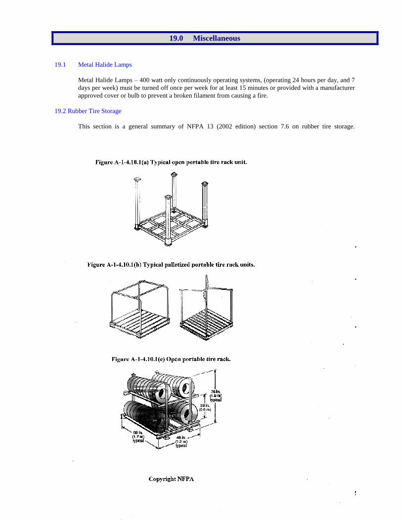
Standard 105 72
19.0 Miscellaneous
19.1 Metal Halide Lamps
Metal Halide Lamps – 400 watt only continuously operating systems, (operating 24 hours per day, and 7
days per week) must be turned off once per week for at least 15 minutes or provided with a manufacturer
approved cover or bulb to prevent a broken filament from causing a fire.
19.2 Rubber Tire Storage
This section is a general summary of NFPA 13 (2002 edition) section 7.6 on rubber tire storage.
definition section of CFS #106 has information on rubber tire storage.
The arrangement of storage is vital to the sprinkler design density. Drawings of the various storage
arrangements and racks are included at the end of section 19.2.
NFPA 13 (latest edition) must be utilized for the protection of rubber tire storage in Chrysler Group LLC
National and Field Depots.
Storage Using Standard Spray Sprinklers
Pyramid piles on side up to 5 feet- 0.19gpm/2000 sq. ft.
Tires on tread on floor 5-12 feet- 0.3gpm/2500 sq. ft.
Portable racks on side storage up to 5 feet. - 0.19 gpm/2000 sq. ft.
5-20 feet - see NFPA
20-25 feet - 0.6 gpm/5,000 sq. ft.
Storage Using Large Drop Sprinkler Protection
On side, on tread, portable racks to 25 feet in a 30 ft. Building- design 15 sprinklers at 75 psi
Storage Using ESFR Sprinkler Protection
On side, on tread, portable racks- up to 25 feet storage in a 30 feet building – design 12 heads at 50 psi
up to 25 feet in a 35 feet building- design 12 heads at 75 psi
Laced tires in portable racks up to 25 feet in a 30 feet building- design 20 heads at 75 psi
In buildings used for tire storage the required sprinkler protection shall extend 15 feet beyond the
perimeter of the tire storage area.
Refer all tire storage over 25 feet to Corporate Fire Engineer and GRC for review and
development of applicable protection recommendations.
Inside small fire hose stations must be provided for final extinguishment of rubber tires.
Column steel protection is required when on floor or on side storage in portable racks are over 15 feet.
This requirement can be waived if ceiling protection can provide both a 0.90-gpm/sq ft. density over the
most remote 3000 sq. ft. and a 0.6-gpm per sq. feet density over the most remote 5,000 sq. ft. using high
temperature sprinkler heads. This protection based on the type of column can be a one-(1) hour rated
coating or sidewall sprinklers at the 15 feet level.
Pile sizes shall be limited to 2,000 square feet with a minimum 8 feet aisle for manual fire fighting.
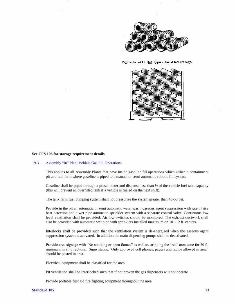
Standard 105 73
See CFS 106 for storage requirement details
19.3 Assembly “In” Plant Vehicle Gas Fill Operations
This applies to all Assembly Plants that have inside gasoline fill operations which utilize a containment
pit and fuel farm where gasoline is piped to a manual or semi-automatic robotic fill system.
Gasoline shall be piped through a preset meter and dispense less than ½ of the vehicle fuel tank capacity
(this will prevent an overfilled tank if a vehicle is fueled on the next shift).
The tank farm fuel pumping system shall not pressurize the system greater than 45-50 psi.
Provide in the pit an automatic or semi automatic water wash, gaseous agent suppression with rate of rise
heat detection and a wet pipe automatic sprinkler system with a separate control valve. Continuous low
level ventilation shall be provided. Airflow switches should be monitored. The exhaust ductwork shall
also be provided with automatic wet pipe with sprinklers installed maximum on 10 –12 ft. centers.
Interlocks shall be provided such that the ventilation system is de-energized when the gaseous agent
suppression system is activated. In addition the main dispensing pumps shall be deactivated.
Provide area signage with “No smoking or open flames” as well as stripping the “red” area zone for 20 ft.
minimum in all directions. Signs stating “Only approved cell phones, pagers and radios allowed in area”
should be posted in area.
Electrical equipment shall be classified for the area.
Pit ventilation shall be interlocked such that if not proven the gas dispensers will not operate
Provide portable first aid fire fighting equipment throughout the area.

Standard 105 74
Do not allow walkie talkies, pagers, cell phones etc. in the area unless they are approved by a recognized
testing agency for use in hazardous locations.
Provide an emergency fuel tank shutdown button in two remote locations from the gas fill operation.
Shutdown button should be interlocked to shutdown conveyor and activate water wash system.
Provide a spring loaded fusible link valve where the incoming gasoline line penetrates the main building
floor or wall and a valve near the fuel pumping equipment.
The gasoline piping from the entry point into the building and the connection point of the fuel dispensers
shall be seamless or welded seam whenever it will be over equipment or processes that emit sparks or
produces heat. These would include welders, ovens and furnaces. The welding of the piping system must
be done by or supervised by a certified welder in pressure piping welding.
All plans for the fuel fill operation or any modifications to the area must be submitted in writing to
Corporate Fire Engineer and GRC for review and comment.
19.4 Hydraulic Fluid Systems
Hydraulic Fluid Systems - New Installations:
Use an FM approved less flammable hydraulic fluid where possible.
Before purchasing new hydraulic equipment, the manufacturer of the equipment should be consulted to
determine if an FM approved less flammable hydraulic fluid could be used in their equipment. Ensure
pumps, seals, gaskets, packing and other system components are checked to ensure they are suitable for
the approved less flammable fluid to be used.
Petroleum based hydraulic fluid systems:
1). Emergency shutoff switches should be provided for shutting down hydraulic pumps in the event of a
pipe failure or fire. Switches shall be well marked and readily accessible under any anticipated fire
conditions.
2). Flexible hose used for connections should be steel reinforced, designed for the hydraulic fluid being
used and capable of withstanding four times the maximum working pressure. Hoses should not rub
against other objects as a result of machine movement, vibration, or pressure surges.
3). Avoid using threaded pipe. However, if used, weld joints using a qualified welder following
American Welding Society (AWS) or ANSI/ASME procedures. A safety factor of eight over maximum
working pressures should be used.
4). Secure/anchor all pipe and tubing to minimize failure due to vibration.
Fire Protection for Petroleum Based Hydraulic Oil Systems:
Sprinkler protection shall be provided over all hydraulic oil equipment unless written permission is
obtained from the Chrysler Group LLC Corporate Fire Prevention Engineer or GRC.
NOTE: Normally this will only occur over a single small hydraulic system associated with a detached
operation located in a non-combustible structure and located adjacent to non-combustible occupancy
(ignition sources normally not present) and the business interruption potential is low i.e., lost production
can be readily made up by other existing equipment and damaged equipment can be readily replaced. A
provision for prompt manual shutdown of the system must be provided.
Standard 105 75
Besides automatic sprinkler protection, the additional degree of protection will depend on two issues –
1). The total quantity of petroleum based hydraulic oil that can be released from hydraulic equipment,
assuming that the pumps are not shutoff and 2) the normal presence of ignition sources during operating
the equipment such as molten metal, heaters, or other hot surfaces above the auto-ignition temperature of
the oil being used, open flames or spark producing equipment, such as welding machines.
As a minimum, provide automatic sprinklers over the hydraulic equipment and at least 20 feet beyond in
all directions. Also, provide sprinkler protection for all shielded areas, such as pits beneath equipment or
platforms.
Sprinkler protection may be dictated by the surrounding occupancy. Based upon Chrysler Group LLC
Standards, minimum sprinkler design shall be 0.30-gpm per sq. ft. over the most remote 4,000 sq. ft. plus
500-gpm hose stream allowance using 286°F sprinklers.
Portable fire extinguishers (Class ABC) suitable for flammable liquids fires shall be provided. Provide a
minimum of a 15# CO2 or 20# dry chemical unit for the area
For any petroleum based hydraulic oil system(s) with individual reservoirs/tanks containing more than
100-gallons of petroleum-based hydraulic oil or aggregate 100-gallon within 20-feet of individual tanks,
an automatic actuated means for shutting down the oil pump(s) and shutting off the flow from
accumulators for hydraulic systems may be required.
If required by the Chrysler Group LLC Corporate Fire Prevention Engineer:
Automatic shutdown of the hydraulic system(s) can be best accomplished by using a thermally actuated
fire detection system (such as linear heat detection wire) located directly above the hydraulic operated
equipment and at least 20 feet beyond in all directions. Interlock the thermally actuated fire detection
system with the emergency stop switch or power supply to the oil pump. The thermal detection device
should be rated at least 50ºF above the highest anticipated operating environment temperature.
The use of using a sprinkler water flow switch as a method to automatically shutoff the hydraulic system
should be discouraged. Same is true for oil reservoir liquid level switches unless it can be proven to
activate the power interlock before 25-gallons or less of hydraulic oil are released.
Large Capacity Systems:
Very large (1,000 gallons or greater capacity) petroleum-base hydraulic oil systems should be located in
a minimum one-hour rated cutoff room protected by automatic sprinklers.
FM Approved Less Hazardous Fluids:
FM approved less hazardous fluids are either of the high water base (oil-in-water emulsion), water-in-oil
emulsion, water-glycol, or synthetic types. These are referred to Internationally as HF-A, HF-B, HF-C
and HF-D fluids respectively.
HF-A fluids contain 90% or more water. They are usually used in light-duty applications –pressure below
1,000 psi using special pumps. Recommended temperature limits are 40ºF to 120ºF.
HF-B fluids consist of 35% to 40% water in mineral oil, with a small amount of emulsifying agent, rust
inhibitors and anti-wear additives. Recommended temperature limits are 15ºF to 150ºF.
HF-C fluids consist of 35% to 50% water for fire resistance, ethylene or propylene glycol to improve low
temperature properties, and additives for proper viscosity and resistance to corrosion, wear and bacteria.
Recommended temperature limits are 0ºF to 150ºF with normal operations at 120ºF to 150ºF.
Most synthetic fluids (HF-D fluids) are one of four types: phosphate esters, chlorinated hydrocarbons,
blends of phosphate esters and chlorinated hydrocarbons, and fluids containing other compositions.
Recommended temperature limits are 20ºF to 200ºF.

Standard 105 76
Synthetic fluids are not compatible with natural rubber, Buna, or neoprene seals or hoses. Synthetic
fluids also may attack metal protective paints, lacquers and electrical wiring insulation.
19.5 Platforms
Platforms (solid and/or grated flooring):
Platforms that are 36-inches or higher, above finished floor, and wider than 48 inches shall be protected
by one of the following methods:
a) An approved skirting method around the perimeter that prevents any storage from being
introduced below the platform.
b) Automatic sprinkler protection designed to provide a minimum density of 0.30-gpm per square
feet over the most remote 4,000 square feet (or entire platform area) plus 500-gpm hose stream
allowance for platforms up to six-feet in height. Platforms six-feet and over in height shall have
sprinkler protection designed to provide a minimum density of 0.60-gpm per square feet over
the most remote 4,000 square feet (or entire platform area) plus 500-gpm hose stream allowance
or as stated by the Corporate Fire Prevention Engineer.
An approved skirting method shall be comprised of one of the following:
a) Sheet metal panels attached around the perimeter by fasteners such as bolts, screws, clips, etc.
Panels shall be able to be removed for a visual inspection and cleaning of any debris that may
collect in the area below the platform.
b) Horizontal metal bars (such as Unistrut) or framework attached to the platform’s vertical
supports and spaced a maximum of 12-inches between horizontal metal bars. Metal bars shall be
attached by a method where access is available for cleaning any debris under the platform.
If the process above the platform involves flammable or combustible liquids then automatic sprinkler
protection shall be installed under the platform regardless of platform height.
Platforms less than 36-inches in height, not utilizing flammable or combustible liquids, shall be arranged
for visual management and cleaning but will not require skirting or automatic sprinkler protection unless
required by the local Authority Having Jurisdiction (AHJ).