
Assembly and Tensioning of High Strength Bolts and …/media/busind/techstdpubs/Technical...TN62...
16
Technical Note 62 Assembly and Tensioning of High Strength Bolts and Nuts - Part 2: Class 10.9 November 2015
Transcript of Assembly and Tensioning of High Strength Bolts and …/media/busind/techstdpubs/Technical...TN62...

Technical Note 62 Assembly and Tensioning of High Strength Bolts and Nuts - Part 2: Class 10.9 November 2015

Technical Note, Transport and Main Roads, November 2015
Copyright
http://creativecommons.org/licenses/by/3.0/au/
© State of Queensland (Department of Transport and Main Roads) 2015
Feedback: Please send your feedback regarding this document to: [email protected]

TN62 Assembly and Tensioning of High Strength Bolts and Nuts - Part 2: Class 10.9
1 Clarification of bolt tensioning
The purpose of this technical note is to define the acceptable requirements for the assembly and tensioning of Class 10.9 bolts for Department of Transport and Main Roads (TMR) projects.
2 Design Requirements
When Class 10.9 bolts are used, the connection design shall use the bolt capacities of a Class 8.8 bolt.
Class 10.9 bolts can be used in lieu of Class 8.8 bolts when there is a concern over the quality of Class 8.8 bolts or the Class 8.8 bolts are not available in a specific size for bridge repairs.
3 Reference documents
A number of reference documents have been used to compile this technical note. The reference documents are outlined below.
• Transport and Main Roads Specification MRTS78 Fabrication of Structural Steelwork
• Australian Standard AS 4100 – 1998 “Steel Structures”
• European Standard EN 14399-4 – 2005 “High-strength structural bolting assemblies for preloading – Part 4: System HV- Hexagon bolt and nut assemblies”
• European Standard EN 14399-6 – 2005 “High-strength structural bolting assemblies for pre-loading- Part 6: Plain chamfered washers”.
4 Identification of conforming materials
All bolts and nuts shall be from tested batches. All bolts and nuts shall be tested in accordance with MRTS78 Fabrication of Structural Steelwork.
The contractor shall only use bolts, nuts and washers complying with EN 14399-4 and EN 14399-6. These bolts, nuts and washers have identification marks embossed on the top of the bolt head, the top surface of the nut and top surface of the washers.
Inspection by the contractor of bolts, nuts and washers for damage to the threads and the galvanising shall take place before fitting. The contractor shall discard any damaged bolts, nuts and washers.
5 Assembly of the bolts, nuts and washers
Class 10.9 bolt assemblies are supplied in individual boxes. Figure 5(a) shows the bolt, nut and washers come in separate boxes, with individual labels.
Prior to the assembly of the bolts, it is important to ensure the bolts match the labels on the box. Figure 5(b) shows the marking on the head of the bolt. Figure 5(c) shows the identification number on the box of bolts. Figure 5(d) shows the lot number on the nut. Figure 5(e) shows the identification number on the box of nuts. If the numbers do not match each other, then the bolts shall be rejected.
When the bolt, washer and nut are assembled, two washers must be installed on the bolt, refer to Figure 5(f). The markings on the washer must go against the face of the surface (chamfer face against the nut and bolt), refer to Figure 5(g).
Technical Note, Transport and Main Roads, November 2015 1

TN62 Assembly and Tensioning of High Strength Bolts and Nuts - Part 2: Class 10.9
Once assembled the labels from the nut and bolt shall be torn off the boxes and installed in the bucket of assembled bolts, refer to Figure 5(h) and Figure 5(i). Once the assemblies are placed in the container, they shall be stored in a covered storage area.
Figure 5(a) – View of the bolt nut and washer boxes
Figure 5(b) – View of the bolt head markings
Figure 5(c) – View of the label on the box of bolts
Technical Note, Transport and Main Roads, November 2015 2

TN62 Assembly and Tensioning of High Strength Bolts and Nuts - Part 2: Class 10.9
Figure 5(d) – View of the nut markings
Figure 5(e) – View of the label on the box of nuts
Figure 5(f) – View of the assembled bolt nut and two washers
Technical Note, Transport and Main Roads, November 2015 3

TN62 Assembly and Tensioning of High Strength Bolts and Nuts - Part 2: Class 10.9
Figure 5(g) – Washers are installed so the chamfered face is against the turning surface
Figure 5(h) – Once assembled the nut and bolt labels are torn off the boxes
Figure 5(i) – Torn off labels are placed with the assembled bolts
Technical Note, Transport and Main Roads, November 2015 4

TN62 Assembly and Tensioning of High Strength Bolts and Nuts - Part 2: Class 10.9
6 Tensioning of bolts
There are three bolting categories defined in AS 4100-1998.
6.1 8.8/S
The bolts are installed and tensioned to “snug tight”. AS 4100 defines snug tight as, "The tightness attained by a few impacts of an impact wrench or by the full effort of a person using a standard podger spanner”, which brings the connecting parts into firm contact.
6.2 8.8/TF and 8.8/TB (or 8.8/T when referring to both types)
The bolts are installed and are fully tensioned in a controlled manner.
There are four methods of tensioning the bolts:
• The use of an adjustable and correctly calibrated torque wrench. The equipment required is a load cell (similar to the Skidmore Willhelm Gauge) and an adjustable torque wrench. The torque wrench is calibrated to the specific bolt and nut combination.
• The use of the part turn method. Please note this method is not permitted as, there is a variation in bolt tension when using this approach.
• The use of load indicator washers. This method is the preferred method in AS 4100 and would be acceptable, provided the load indicator washer is clearly visible for inspection.
• Alternative Method. Some bolts/rivets requiring replacement in existing structures have the nuts located inside chord members. This would make checking the gap between the load indicating washer difficult to inspect. By using an adjustable torque wrench, calibration of the system could occur by assembling a series of bolts, nuts and load indicating washers in a simple joint on site. Calibration of the torque wrench would be by using load indicator washers to determine the appropriate wrench setting for field usage.
7 Non acceptable method of tensioning bolts
For the tensioning of T/F and T/B bolts, the part turn method is not acceptable for the following reasons.
A typical structural bolt, for example a M24 bolt will typically require a torque of approximately 800 Nm in order to fully tension the bolt. A torque of 800 Nm is equivalent to applying a force of 81kg over a 1000 mm long spanner. The normal podge spanner is roughly 500 mm long, so assuming that the force could only be applied at about 400 mm, you would need to apply a force of 204kg at this distance.
In the past workers would place extensions on standard spanners in order to tension bolts, refer to Figure 7. This process is both risky from a safety perspective and does not ensure a consistent tension force is applied to all the bolts.
It is not practical to apply forces of this magnitude to a spanner particularly when working at heights. Hence why manual tensioning of bolts is not permitted.
Technical Note, Transport and Main Roads, November 2015 5

TN62 Assembly and Tensioning of High Strength Bolts and Nuts - Part 2: Class 10.9
Figure 7 – Extension placed on the end of a ring spanner
8 Acceptable method for tensioning bolts
The accepted method for fully tensioning T/F and T/B bolts is as follows. For the tensioning of the Class 10.9 bolts, only a calibrated torque wrench can be used.
8.1 Types of tensioning equipment
Figure 8.1(a) – Electric torque wrench – Accuracy of +/- 4%
Technical Note, Transport and Main Roads, November 2015 6
TN62 Assembly and Tensioning of High Strength Bolts and Nuts - Part 2: Class 10.9
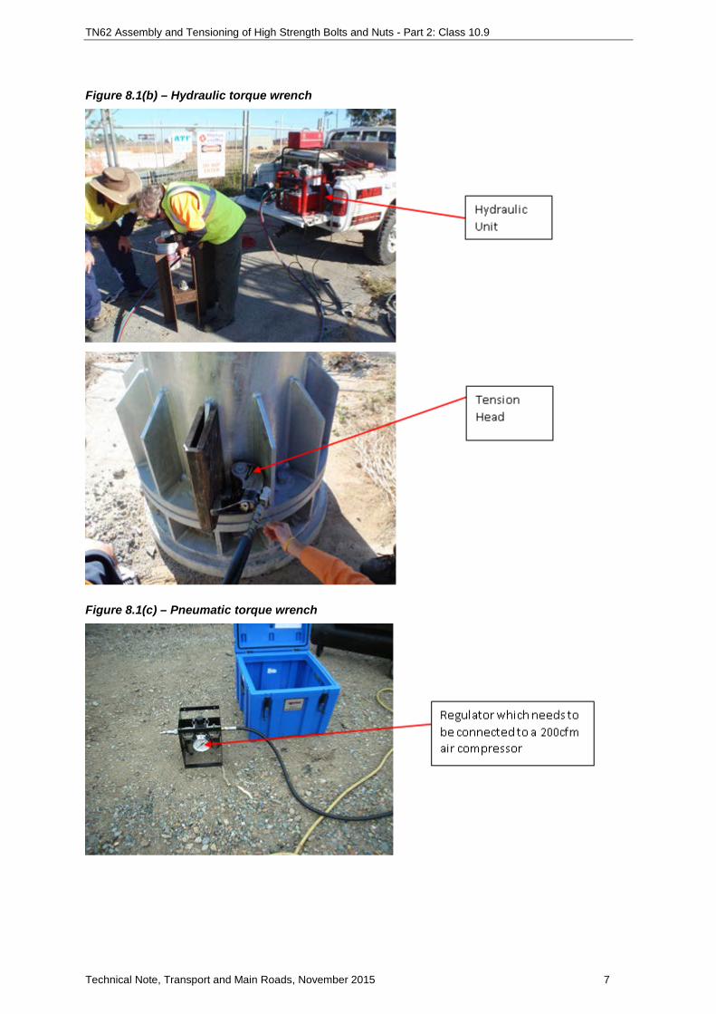
Figure 8.1(b) – Hydraulic torque wrench
Figure 8.1(c) – Pneumatic torque wrench
Technical Note, Transport and Main Roads, November 2015 7

TN62 Assembly and Tensioning of High Strength Bolts and Nuts - Part 2: Class 10.9
8.2 Calibrated Torque Wrench
In order to ensure that the torque wrench is correctly calibrated, the following process shall be used.
1. Note: Each batch of bolt and nut combination shall be calibrated as outlined above. 2. Place a Class 10.9 bolt assembly in a Skidmore Willhelm Gauge, refer to Figure 8.2(a). The
nut is located on the gauge side, refer to Figure 8.2(b) and the bolt head is secured in the spacers to prevent the head turning, refer to Figure 8.2(c). Note: Lubricate the bolt thread with “Wax” prior to installing the nut on the bolt.
3. Tighten the nut with a calibrated torque wrench to the tension force outlined in Table 8.2 for the specific bolt size, refer to Figure 8.2(d). (The values are determined from AS 4100).
4. It is important the torque wrench stops turning within the minimum and maximum tension force range outlined in Table 8.2 for the specific bolt size. The torque wrench will need to be adjusted to ensure the correct tension is achieved.
5. Once the torque wrench has been set for the specific bolt and nut, the torque wrench is placed on a Norbar True Checker, refer to Figure 8.2(e). The True Checker will confirm the torque setting for that specific bolt and nut combination.
6. To gain a true and accurate representation of the bolt batch, steps one to six shall be repeated for three more bolts.
Technical Note, Transport and Main Roads, November 2015 8

TN62 Assembly and Tensioning of High Strength Bolts and Nuts - Part 2: Class 10.9
7. Write the average torque setting and pressure setting on the back of the bolt label, so the torque setting can be cross checked as per Table 10.2 “Check of Torque Setting”, refer to Figure 8.2(f).
Figure 8.2(a) – View of a skidmore
Figure 8.2(b) – View of the nut end in the skidmore
Figure 8.2(c) – View of the bolt head in the skidmore
Technical Note, Transport and Main Roads, November 2015 9

TN62 Assembly and Tensioning of High Strength Bolts and Nuts - Part 2: Class 10.9
Figure 8.2(d) – View of the tension in the bolt for a specific torque
Figure 8.2(e) – View of the torque wrench on the True Checker
Figure 8.2(f) – View of an example of the torque and pressure values on the bolt label
True Checker device is used to outline the torque setting for a torque wrench. Many wenches are set via pressure and the true checker determines the torque in the torque wrench for a specific pressure. True Checker can also be used to ensure the torque in the torque wrench correctly calibrated.
Technical Note, Transport and Main Roads, November 2015 10

TN62 Assembly and Tensioning of High Strength Bolts and Nuts - Part 2: Class 10.9
Table 8.2 – Minimum bolt tension
Nominal diameter of bolt Minimum Bolt Tension kN Max Upper Limit Bolt Tension kN
M16 95 115
M20 145 185
M22 180 (Note 1) 230 (Note 1)
M24 210 265
M30 335 420
M36 490 610
Note 1: M22 tension capacity based on linear interpolation
9 Installation of the bolts, nuts and washers
The nut must be able to run freely up and down the bolt. The correct way to clear a blockage is to run the nut up and down the thread until the nut is free running. If the nut still will not run freely on the bolt the contractor shall discard the nut and the bolt. This procedure must occur before taking bolts and nuts to site.
The contractor shall draw together the two surfaces which require joining so they are in full contact. This may involve the use of tacking bolts. Once the parts are in full contact, the contractor shall replace any tacking bolts with high strength bolts one at a time.
The following requirements are to be satisfied:
• Driving of high strength bolts into the holes is unacceptable. In order to fit the bolts without force, the contractor may ream or drift the holes.
• Washers are required under both the head of the bolt and the nut.
• Lubricate the bolt thread with “Stearin Wax” or “Relton Stick Wax” prior to installing the nut on the bolt.
• There shall be a minimum of one full thread projecting above the top of the nut after assembly.
• If one full thread is not visible, then a longer bolt shall be used. If selecting a longer bolt, the maximum amount of projection of the bolt end passed the nut shall be 15 mm. Packing with up to three washers not exceeding 12 mm thickness is acceptable on the joint side not being turned.
• Note: The reason a bolt cannot have to too much thread projection is due to the bolt not having sufficient thread and when tightened the nut can run out of thread and will not be tensioned correctly.
• Once all the bolts are assembled, the bolts shall be tensioned so they are snug tight and the connecting surfaces are drawn together.
Technical Note, Transport and Main Roads, November 2015 11

TN62 Assembly and Tensioning of High Strength Bolts and Nuts - Part 2: Class 10.9
10 Check of torque and re-calibration
Once all the initial calibration of the torque wrench for each bolt and nut combination and has been completed, it is important to ensure the torque wrench is operating at the correct settings.
10.1 Check of torque setting
During the course of a working shift, the torque setting will need to be checked as per the requirement outlined in Table 10.2, “Check of Torque Setting”. To check the torque the torque wrench is placed on the True Checker and the torque wrench operated until it stops turning. The torque setting on the display should match the settings recorded for that specific bolt and nut. If the torque value when checked is slightly out, then torque wrench shall be adjusted so the correct torque is achieved.
Note: the tolerance on the torque setting shall not vary by more than +/- 10 Nm.
10.2 Re-calibration
It is also important to ensure the torque wrench is correctly calibrated. The checking of the calibration is dependent on how often the bolts are being tightened on a project. Table 10.2 “Recalibration Requirements”, outlines the frequency at which the re-calibration should be performed.
To carry out the re-calibration Section 8.2 “Calibrated Torque Wrench” is followed using one bolt from the previously tested batch of bolts.
Table 10.2 – Torque Check and Re -Calibration Testing
Time between Last Bolt Assembly
Check of Torque Setting Recalibration Requirement
Tension bolts on a daily basis
Start of Day Shift, 11am – 12pm and 2pm - 3pm or Start of Night Shift, 11pm – 12am and 2am – 3am
On a monthly basis
Tension bolts on a weekly basis
Start of Day Shift, 11am – 12pm and 2pm - 3pm or Start of Night Shift, 11pm – 12am and 2am – 3am
On a weekly basis
Tension bolts on a monthly basis or longer
Start of Day Shift, 11am – 12pm and 2pm - 3pm or Start of Night Shift, 11pm – 12am and 2am – 3am
Before undertaking work on a bolted joint
11 Marking of tensioned bolts
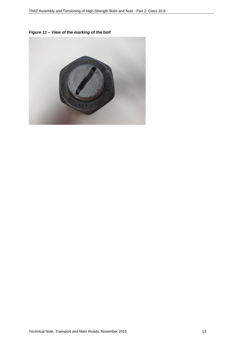
Once a bolt assembly has been tensioned, the bolt on the nut end shall be marked with a paint pen to signify the bolt has been tensioned, refer to Figure 11.
Technical Note, Transport and Main Roads, November 2015 12
TN62 Assembly and Tensioning of High Strength Bolts and Nuts - Part 2: Class 10.9
Figure 11 – View of the marking of the bolt
Technical Note, Transport and Main Roads, November 2015 13


![Post Tensioning[1]](https://static.fdocuments.net/doc/165x107/543ffc0bafaf9fff098b4bcd/post-tensioning1.jpg)