ASG XPAC Smart Arm Setup -...
3
1 Revision Date: 5.29.2012 ASG XPAC Setup Procedure Description: This procedure describes the process to configure the Smart Motion Smart Arm controller to communicate with the ASG XPAC driver controller. Smart Box Configuration: 1. Log into Maintenance mode using PIN 7439 2. Scroll through Maintenance menu until you see “OUTTYP” 3. Select “OUTTYP” via the jog dial and scroll through and select output type “KLv d0” 4. Connect Smart arm controller to XPAC using cable assembly SA-0040-00023 as per detail below: XPAC Configuration: 1. The Smart controller enables or disables the ASG tool based on the selected bolt input. Each bolt must have an assigned input pattern that matches the selected input from the smart controller. The Smart controller can select up to 8 different bolt settings. If the Smart arm is not in the programmed location all inputs to the XPAC will be on. Once the tool has been moved to the required location, the Smart controller will enable the preprogrammed torque program, see the table below for the correct input pattern.
-
Upload
nguyenthuy -
Category
Documents
-
view
228 -
download
2
Transcript of ASG XPAC Smart Arm Setup -...

1
Revision Date: 5.29.2012
ASG XPAC Setup Procedure
Description:
This procedure describes the process to configure the Smart Motion Smart Arm controller to communicate with the ASG XPAC driver controller.
Smart Box Configuration:
1. Log into Maintenance mode using PIN 7439
2. Scroll through Maintenance menu until you see “OUTTYP”
3. Select “OUTTYP” via the jog dial and scroll through and select output type “KLv d0”
4. Connect Smart arm controller to XPAC using cable assembly SA-0040-00023 as per detail below:
XPAC Configuration:
1. The Smart controller enables or disables the ASG tool based on the selected bolt input. Each bolt must have an assigned input pattern that matches the selected input from the smart controller. The Smart controller can select up to 8 different bolt settings. If the Smart arm is not in the programmed location all inputs to the XPAC will be on. Once the tool has been moved to the required location, the Smart controller will enable the preprogrammed torque program, see the table below for the correct input pattern.

2
Revision Date: 5.29.2012
Smart Box ASG XPAC
Torque Input 1 Input 2 Input 3 Input 4 Input 5 Input 6 Input 7 Input 8
TQ0 L H H H H H H H
TQ1 H L H H H H H H
TQ2 H H L H H H H H
TQ3 H H H L H H H H
TQ4 H H H H L H H H
TQ5 H H H H H L H H
TQ6 H H H H H H L H
TQ7 H H H H H H H L
Note: If using the 4 input smart controller cable, inputs 5, 6, 7 and 8 will be set to “Ignore”.
Sample Screen on XPAC for TQ1, using 4 input cable.
3
Revision Date: 5.29.2012
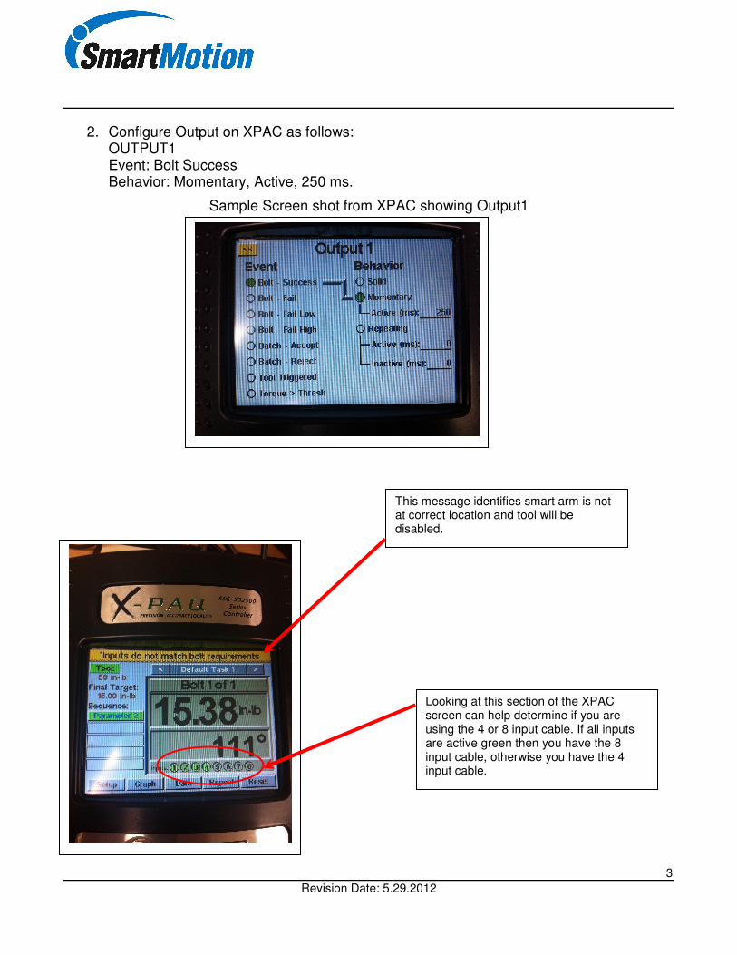
2. Configure Output on XPAC as follows: OUTPUT1 Event: Bolt Success Behavior: Momentary, Active, 250 ms.
Sample Screen shot from XPAC showing Output1
This message identifies smart arm is not at correct location and tool will be disabled.
Looking at this section of the XPAC screen can help determine if you are using the 4 or 8 input cable. If all inputs are active green then you have the 8 input cable, otherwise you have the 4 input cable.