Air diffusers - introduction and technical overview TYPE REFERENCE AIR FLOW RANGE (l/s/m2 of space)...
8
Publication DIFFUSERS section 2 SEPT 2005 PART A R Air Diffusers supply and exhaust ventilation systems introduction and technical overview
Transcript of Air diffusers - introduction and technical overview TYPE REFERENCE AIR FLOW RANGE (l/s/m2 of space)...
Publication
DIFFUSERSsection 2 SEPT 2005
PART A
R
Air Diffuserssupply and exhaust ventilation systems
introduction and technical overview
introduction
fixings
finishes
manufacture
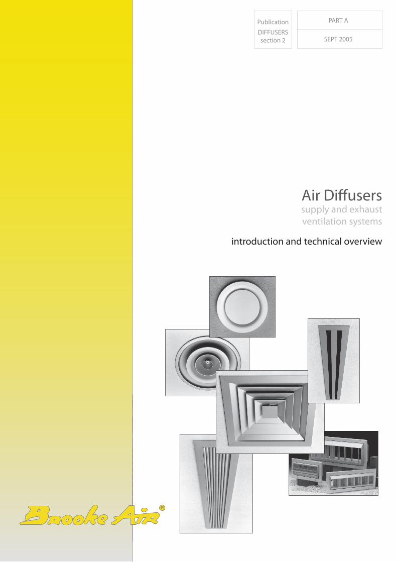
The comprehensive range of air diffusers detailed in this literature has been developed over many years to meet the architectural and system design requirements of the building services industry.
The range covers conventional diffusion products such as continuous slot air distribution systems, square and circular diffusers, as well as the more specialist products for industrial applications such as laminar flow panels and Drum Jets.
The range is manufactured from anodised aluminium extrusions and spinnings using fabrication and construction techniques designed to produce a high quality, robust product.
In keeping with modern architectural demands for specialist materials and product finishes, much of the grille and diffuser range can also be offered in polished brass, stainless steel, or coloured anodising.
In addition to this, the Company also specialises in architectural integration and can offer a variety of products in curved or circular formats to suit customer requirements.
Standard finish for the diffuser range is either silver anodised aluminium or white stove enamelled paint, as detailed under each product. Numerous optional paint finishes are available in the BS and RAL colour ranges.
Diffuser fixings are generally of the concealed type, utilising either backstrap, yoke strap or fixing collar, depending on the product. Where applicable, optional fixing methods are listed for each type.
DiffusersGENERAL INTRODUCTION
2
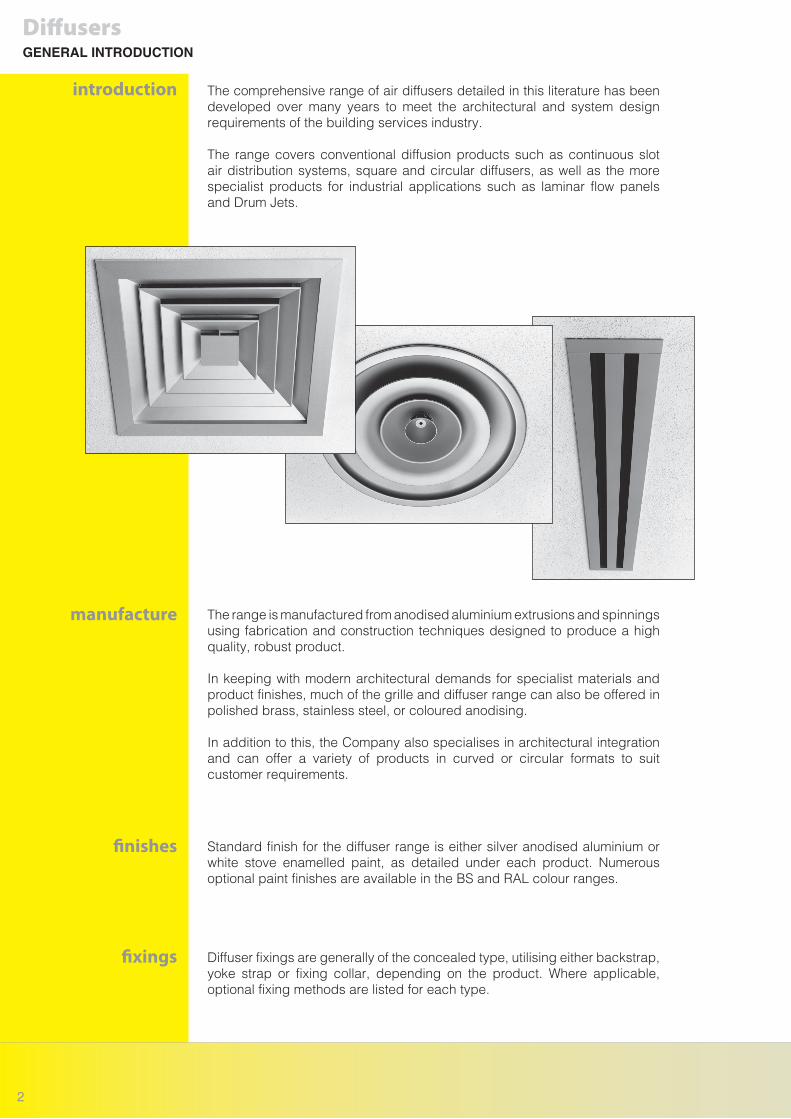
Conventional air diffusion terminals utilise the ceiling or any flat mounting surface to diffuse the supply air horizontally in a single or multidirectional throw pattern. The same principle can also be used with coffered or open lattice ceilings, although the jet coverage is invariably reduced.
Most types of terminal can be used in this manner providing the mounting height is adequate and due consideration is given to the influence of temperature differential on the jet trajectory. In some Instances It may be necessary to provide a localised mounting surface to initiate horizontal diffusion.
Blades or cores can be adjusted on certain types of diffuser to project the air vertically downwards for heating or spot cooling applications. To ensure comfort conditions, selections should normally be based on the heating cycle.
In situations where it is necessary to maintain visual continuity, supply diffusers can also be used to exhaust air from the zone. Allowance should be made for increases in pressure loss and noise level.
To assist with diffuser selections the following symbols are used throughout the catalogue.
DiffusersAIR DIFFUSION PRINCIPLES AND PRODUCT SELECTION
ceiling jet
free jet - exposed duct or bulkhead installation
vertical projection
exhaust
selection applications
3
R
DIFFUSER TYPE REFERENCE AIR FLOW RANGE
(l/s/m2 of space)
Square or Rectangular Multicore
Linear Slot or Louvre Diffuser
Circular Diffuser or Drum Jets
IC
LCS FlowlineF45C
MRSADJ
5 - 20
5 - 25
10 - 35
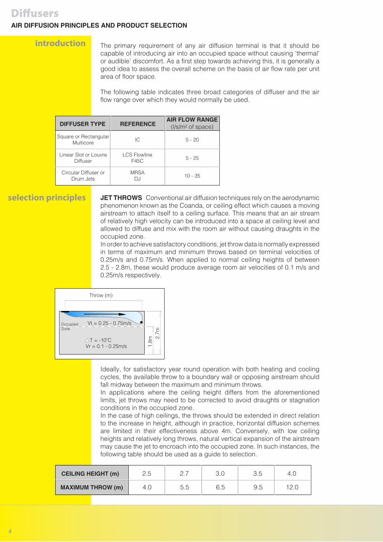
Throw (m)
OccupiedZone
T = -10oCVr = 0.1 - 0.25m/s
Vt = 0.25 - 0.75m/s
1.8m
2.7m
CEILING HEIGHT (m) 2.5 2.7 3.0 3.5 4.0
MAXIMUM THROW (m) 4.0 5.5 6.5 9.5 12.0
The primary requirement of any air diffusion terminal is that it should be capable of introducing air into an occupied space without causing ‘thermal’ or audible’ discomfort. As a first step towards achieving this, it is generally a good idea to assess the overall scheme on the basis of air flow rate per unit area of floor space.
The following table indicates three broad categories of diffuser and the air flow range over which they would normally be used.
JET THROWS Conventional air diffusion techniques rely on the aerodynamic phenomenon known as the Coanda, or ceiling effect which causes a moving airstream to attach itself to a ceiling surface. This means that an air stream of relatively high velocity can be introduced into a space at ceiling level and allowed to diffuse and mix with the room air without causing draughts in the occupied zone. In order to achieve satisfactory conditions, jet throw data is normally expressed in terms of maximum and minimum throws based on terminal velocities of 0.25m/s and 0.75m/s. When applied to normal ceiling heights of between 2.5 - 2.8m, these would produce average room air velocities of 0.1 m/s and 0.25m/s respectively.
Ideally, for satisfactory year round operation with both heating and cooling cycles, the available throw to a boundary wall or opposing airstream should fall midway between the maximum and minimum throws. In applications where the ceiling height differs from the aforementioned limits, jet throws may need to be corrected to avoid draughts or stagnation conditions in the occupied zone. In the case of high ceilings, the throws should be extended in direct relation to the increase in height, although in practice, horizontal diffusion schemes are limited in their effectiveness above 4m. Conversely, with low ceiling heights and relatively long throws, natural vertical expansion of the airstream may cause the jet to encroach into the occupied zone. In such instances, the following table should be used as a guide to selection.
DiffusersAIR DIFFUSION PRINCIPLES AND PRODUCT SELECTION
selection principles
introduction
4
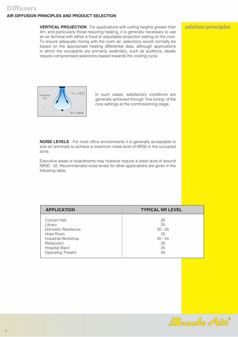
T = -10oCProjection
(m)
Vt = 0m/s
APPLICATION TYPICAL NR LEVEL
Concert HallLibraryDomestic ResidenceHotel RoomIndustrial WorkshopRestaurantHospital WardOperating Theatre
2025
20 - 2525
45 - 55302535
VERTICAL PROJECTION For applications with ceiling heights greater than 4m, and particularly those requiring heating, it is generally necessary to use an air terminal with either a fixed or adjustable projection setting on the core. To ensure adequate mixing with the room air, selections would normally be based on the appropriate heating differential data, although applications in which the occupants are primarily sedentary, such as auditoria, ideally require compromised selections biased towards the cooling cycle.
In such cases, satisfactory conditions are generally achieved through ‘fine tuning’ of the core settings at the commissioning stage.
NOISE LEVELS For most office environments it is generally acceptable to size air terminals to achieve a maximum noise level of NR35 in the occupied zone.
Executive areas or boardrooms may however require a lower level of around NR30 - 32. Recommended noise levels for other applications are given in the following table.
DiffusersAIR DIFFUSION PRINCIPLES AND PRODUCT SELECTION
seletion principles
5
R
DiffusersRANGE SUMMARY
Continuous Slot DiffusersLCS and Flowline seriesSection B
Linear Louvre DiffusersF45L seriesSection B
Plenums for Continuous Slot and Linear Louvre DiffusersPB seriesSection H
Multi Core Square andRectangular Diffusers,Plenums and Pan adaptorsIC series, ICP and PASection C
6
DiffusersRANGE SUMMARY
Laminar Flow PanelsLFP seriesSection D
Circular DiffusersMRA series
Section E
Drum Jet DiffusersDJ seriesSection F
Supply and Extract ValvesK series
Section G
7
R
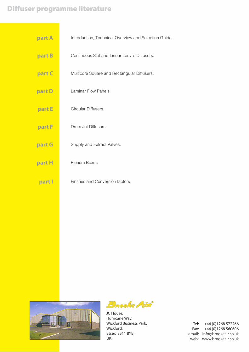
Introduction, Technical Overview and Selection Guide.part A
Tel: +44 (0)1268 572266Fax: +44 (0)1268 560606
email: [email protected]: www.brookeair.co.uk
JC House,Hurricane Way,Wickford Business Park,Wickford,Essex SS11 8YB,UK.
Diffuser programme literature
R
Continuous Slot and Linear Louvre Diffusers.part B
Multicore Square and Rectangular Diffusers.part C
Laminar Flow Panels.part D
Circular Diffusers.part E
Drum Jet Diffusers.part F
Supply and Extract Valves.part G
Plenum Boxespart H
Finshes and Conversion factorspart I