PDF Compressor Pro Feed-Through - … Clamp Feed through terminals are the most versa-tile terminals...
46
CTS2.5U-N Altech “U” Series Universal Rail Mounting Standard Screw Clamp Feed through terminals are the most versa- tile terminals for wire-to-wire connection in control, automation, instrumentation and power distribution appli- cations. A special design fea- ture on the flexible foot enables easy mounting and dismounting from the DIN Rail with the help of a screwdriver. The CTC4U Tab Connection terminals offer quick connec- tion possibility. These terminal blocks are suited for standard ‘Fast On’ type lugs. The connection is achieved by pushing the lug / ferrule onto the tab blade of the terminal block. CTC4U is used primarily in railway systems. A nice alternative to ‘Fast On’ style barrier strips. Terminal Width Height x Length Stripping Length Insulation Material Type of Connection Approvals Wire Range Rated Cross Section 1 conductor per clamp 2 same size conductors Voltage Rating Current Rating Torque Tab Blade Size Other Approvals Terminal Block End Plate Isolation Partition Separator Plate DIN Rail for ordering information refer to pages 90-91 End Stop for ordering info. refer to page 92 Internal Jumper Insulated Internal Jumper Current Bars Shorting Sleeve & Screw External Jumper Test Socket Marking Tags 2 pole 3 pole 4 pole 10 pole 100 pole 2 pole 3 pole 4 pole 10 pole 100 pole 2 pole 3 pole 4 pole 10 pole 10 pole (breakable) 100 pole 2 pole 3 pole 4 pole 10 pole 5 mm 45 x 43 mm 8 mm Polyamide 6.6 22-12AWG 0.2-2.5sq.mm 22-12AWG 600 V 1000 V 600 V 25 A 24 A 25 A 7 lb-in 0.4 Nm 7 lb-in Cat. No. Std. Pk. CTS2.5U-N 100 EP2.5/4UN 50 PP2.5/4UN 50 SP2.5/4UN 100 CA702 50 CA802 50 CA721/2 100 CA721/3 50 CA721/4 50 CA721/10 10 CA721/100 10 CA741/2 100 CA741/3 50 CA741/4 50 CA741/10 10 CA741/100 10 CA703/01 100 CA704/01 100 CA705/01 100 CA731/10 100 — CA731/100 10 CA 707/S/Q/01 100 CA717/2 100 CA717/3 100 CA717/4 100 CA717/10 25 MT5 100 COLOR BLOCKS (otherthanstandardgrey) When ordering please add color suffix to Cat. No. ExampleforcolorRed:Cat.No./R Color OrderingSuffix Red R Yellow Y Blue BU Green G ConsultAltechforavailability: Orange O Beige BG Dark Brown DB Black BL White W * 35A with one No. 10 AWG and 40A with two No. 12 AWG wires. Altech Corp. ® • 35 Royal Road • Flemington, NJ 08822-6000 • Phone (908)806-9400 • FAX (908)806-9490 • www.altechcorp.com 8 E220514 60947-7-1 AExeII ExeIIU Feed-Through MountingHandle Seepage91. 2screwclamps&1tappedhole forcrossconnect. CTS4U-N 6 mm 45 x 43 mm 8 mm Polyamide 6.6 22-10AWG 0.2-4sq.mm 22-10AWG 600 V 1000 V 600 V 35/40 A* 32 A 35/40A* 7 lb-in 0.5 Nm 7 lb-in Cat. No. Std. Pk. CTS4U-N 100 EP2.5/4UN 50 PP2.5/4UN 50 SP2.5/4UN 100 CA702 50 CA802 50 CA722/2 100 CA722/3 50 CA722/4 50 CA722/10 10 CA722/100 10 CA742/2 100 CA742/3 50 CA742/4 50 CA742/10 10 CA742/100 10 CA703/01 100 CA704/01 100 CA705/01 100 CA732/10 100 CA732/10-A 100 CA732/100 10 CA 707/S/Q/01 100 CA714/2 100 CA714/3 100 CA714/4 100 CA714/10 25 MT6 100 E220514 60947-7-1 AExeII ExeIIU 2screwclamps&1tappedhole forcrossconnect. CTC4U 6 mm 49.5 x 47 mm 9 mm Polyamide 6.6 0.25-4.0sq.mm 24-12AWG 0.25-2.5sq.mm 24-12AWG 300 V 32 A 6.3 x 0.8 Cat. No. Std. Pk. CTS4U 100 EPCTC4U 50 CA702 50 CA802 50 CA727/2 100 CA727/3 50 CA727/4 50 CA727/10 10 CA747/2 100 CA747/3 50 CA747/4 50 CA747/10 10 CA703/1 100 CA704/1 100 CA705/1 100 CA732/10 100 CA732/10-A 100 CA732/100 10 CA807/S/Q/01 100 CA707/TS/01 100 CA707/TS/01 100 MT6 100 NEW NEW 5tabconnectionpointsand 1tappedholeforcrossconnection PDF Compressor Pro www.tier1automation.com
Transcript of PDF Compressor Pro Feed-Through - … Clamp Feed through terminals are the most versa-tile terminals...
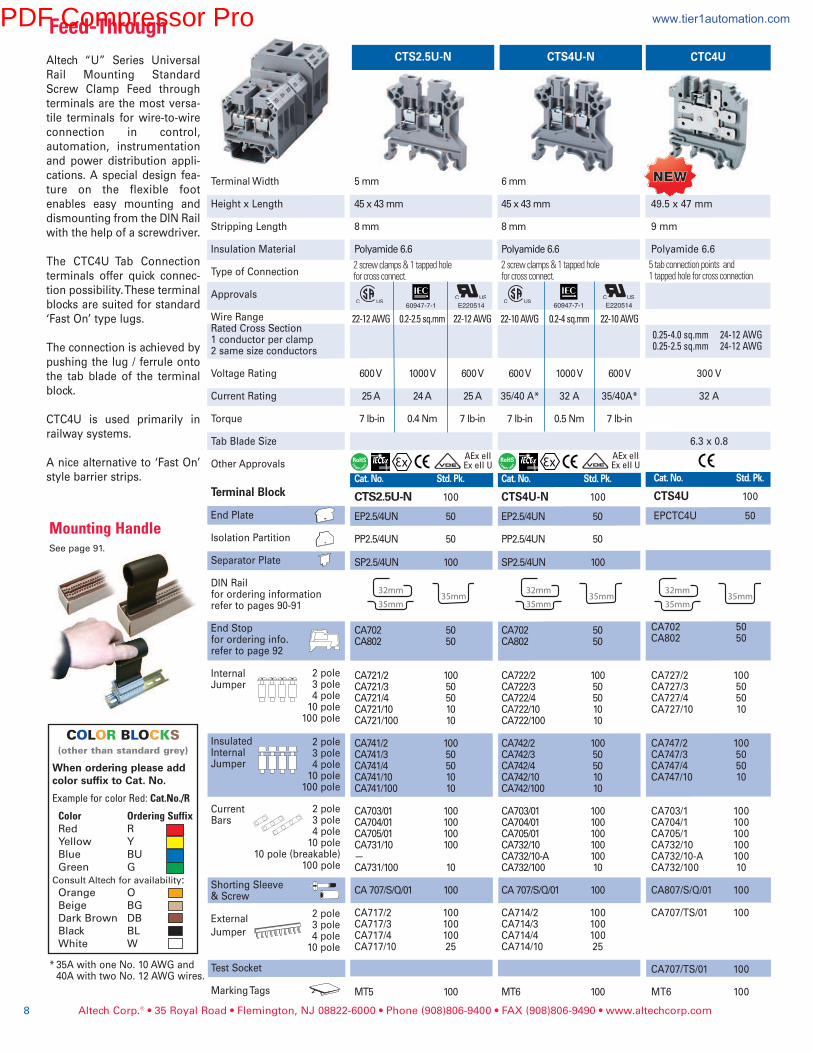
CTS2.5U-NAltech “U” Series Universal
Rail Mounting Standard
Screw Clamp Feed through
terminals are the most versa-
tile terminals for wire-to-wire
connection in control,
automation, instrumentation
and power distribution appli-
cations. A special design fea-
ture on the flexible foot
enables easy mounting and
dismounting from the DIN Rail
with the help of a screwdriver.
The CTC4U Tab Connection
terminals offer quick connec-
tion possibility. These terminal
blocks are suited for standard
‘Fast On’ type lugs.
The connection is achieved by
pushing the lug / ferrule onto
the tab blade of the terminal
block.
CTC4U is used primarily in
railway systems.
A nice alternative to ‘Fast On’
style barrier strips.
Terminal Width
Height x Length
Stripping Length
Insulation Material
Type of Connection
Approvals
Wire RangeRated Cross Section1 conductor per clamp2 same size conductors
Voltage Rating
Current Rating
Torque
Tab Blade Size
Other Approvals
Terminal Block
End Plate
Isolation Partition
Separator Plate
DIN Railfor ordering informationrefer to pages 90-91
End Stopfor ordering info.refer to page 92
InternalJumper
InsulatedInternalJumper
CurrentBars
Shorting Sleeve& Screw
External
Jumper
Test Socket
Marking Tags
2 pole3 pole4 pole10 pole
100 pole
2 pole3 pole4 pole10 pole
100 pole
2 pole3 pole4 pole10 pole
10 pole (breakable)100 pole
2 pole3 pole4 pole10 pole
5 mm 45 x 43 mm
8 mm
Polyamide 6.6
22-12AWG 0.2-2.5sq.mm 22-12AWG
600 V 1000 V 600 V
25 A 24 A 25 A
7 lb-in 0.4 Nm 7 lb-in
Cat. No. Std. Pk.
CTS2.5U-N 100
EP2.5/4UN 50
PP2.5/4UN 50
SP2.5/4UN 100
CA702 50 CA802 50
CA721/2 100 CA721/3 50 CA721/4 50 CA721/10 10 CA721/100 10
CA741/2 100 CA741/3 50 CA741/4 50 CA741/10 10 CA741/100 10
CA703/01 100 CA704/01 100 CA705/01 100 CA731/10 100 — CA731/100 10
CA 707/S/Q/01 100
CA717/2 100 CA717/3 100 CA717/4 100 CA717/10 25
MT5 100
COLOR BLOCKS(otherthanstandardgrey)
When ordering please addcolor suffix to Cat. No.
ExampleforcolorRed:Cat.No./R
Color OrderingSuffixRed R
Yellow Y
Blue BU
Green G
ConsultAltechforavailability:Orange O
Beige BG
Dark Brown DB
Black BL
White W
*35A with one No. 10 AWG and 40A with two No. 12 AWG wires.
Altech Corp.® • 35 Royal Road • Flemington, NJ 08822-6000 • Phone (908)806-9400 • FAX (908)806-9490 • www.altechcorp.com8
E22051460947-7-1
AExeIIExeIIU
Feed-Through
MountingHandleSeepage91.
2screwclamps&1tappedholeforcrossconnect.
CTS4U-N
6 mm 45 x 43 mm
8 mm
Polyamide 6.6
22-10AWG 0.2-4sq.mm 22-10AWG
600 V 1000 V 600 V
35/40 A* 32 A 35/40A*
7 lb-in 0.5 Nm 7 lb-in
Cat. No. Std. Pk.
CTS4U-N 100
EP2.5/4UN 50
PP2.5/4UN 50
SP2.5/4UN 100
CA702 50 CA802 50
CA722/2 100 CA722/3 50 CA722/4 50 CA722/10 10 CA722/100 10
CA742/2 100 CA742/3 50 CA742/4 50 CA742/10 10 CA742/100 10
CA703/01 100 CA704/01 100 CA705/01 100 CA732/10 100 CA732/10-A 100 CA732/100 10
CA 707/S/Q/01 100
CA714/2 100 CA714/3 100 CA714/4 100 CA714/10 25
MT6 100
E22051460947-7-1
AExeIIExeIIU
2screwclamps&1tappedholeforcrossconnect.
CTC4U
6 mm
49.5 x 47 mm
9 mm
Polyamide 6.6
0.25-4.0sq.mm 24-12AWG0.25-2.5sq.mm 24-12AWG
300 V
32 A
6.3 x 0.8
Cat. No. Std. Pk.
CTS4U 100
EPCTC4U 50
CA702 50CA802 50
CA727/2 100CA727/3 50CA727/4 50CA727/10 10
CA747/2 100CA747/3 50CA747/4 50CA747/10 10
CA703/1 100CA704/1 100CA705/1 100CA732/10 100CA732/10-A 100CA732/100 10
CA807/S/Q/01 100
CA707/TS/01 100
CA707/TS/01 100
MT6 100
NEWNEW
5tabconnectionpointsand1tappedholeforcrossconnection
PDF Compressor Pro www.tier1automation.com
Altech Corp.® • 35 Royal Road • Flemington, NJ 08822-6000 • Phone (908)806-9400 • FAX (908)806-9490 • www.altechcorp.com 9
CTS16U
12 mm
47 x 43 mm
12 mm
Polyamide 6.6
2screwclamps&1tappedholeforcrossconnect.
22-6AWG 0.2-16sq.mm 20-4AWG
600 V 1000 V 600 V
70 A 76 A 85 A
14 lb-in 1.2 Nm 14 lb-in
Cat. No. Std. Pk.
CTS16U 50
SP6/10U 100
CA702 50CA802 50
CA751/2 50CA751/3 50CA751/4 50CA751/10 10
CA761/2 50 CA761/3 50 CA761/4 50 CA761/10 10
CA703/8 100CA704/8 100CA705/8 100CA739/10 100
CA707/S/Q/1 100
MT12 100
CTS6U CTS10U CTS25U
8 mm
47 x 43 mm
9 mm
Polyamide 6.6
2screwclamps&1tappedholeforcrossconnect.
22-8AWG 0.5-6sq.mm 22-8AWG
600 V 1000 V 600 V
50 A 41 A 50 A
14 lb-in 0.8 Nm 14 lb-in
Cat. No. Std. Pk.
CTS6U 50
EP6/10U 50
PP6/10U 50
SP6/10U 100
CA702 50CA802 50
CA723/2 100 CA723/3 50CA723/4 50CA723/10 10
CA743/2 100 CA743/3 50 CA743/4 50 CA743/10 10
CA703/2 100CA704/2 100CA705/2 100CA733/10 100
CA707/S/Q/1 100
CA710/2 100CA710/3 100CA710/4 100CA710/10 25
MT8 100
10 mm
47 x 43 mm
11 mm
Polyamide 6.6
2screwclamps&1tappedholeforcrossconnect.
22-6AWG 0.5-10sq.mm 16-6AWG
600 V 1000 V 600 V
65 A 57 A 65 A
14 lb-in 1.2 Nm 14 lb-in
Cat. No. Std. Pk.
CTS10U 50
EP6/10U 50
PP6/10U 50
SP6/10U 100
CA702 50CA802 50
CA724/2 100CA724/3 50CA724/4 50CA724/10 10
CA744/2 100 CA744/3 50 CA744/4 50 CA744/10 10
CA703/3 100CA704/3 100CA705/3 100CA734/10 100
CA707/S/Q/01 100
CA718/2 100CA718/3 50CA718/4 50CA718/10 25
MT10 100
12 mm
56 x 49 mm
14 mm
Polyamide 6.6
2screwclamps&1tappedholeforcrossconnect.
12-2AWG 4-25sq.mm14-2AWG
600 V 1000 V 600 V
115 A 101 A 115 A
35 lb-in 2.0 Nm 25 lb-in
Cat. No. Std. Pk.
CTS25U 50
EP25U
PP25U 50
CA702 50CA802 50
CA725/2 50CA725/3 25CA725/4 25CA725/10 10
CA745/2 50 CA745/3 25 CA745/4 25 CA745/10 10
CA703/4 100CA704/4 100CA705/4 100CA735/10 100
CA707/S/Q/2 100
MT12 100
60947-7-1 60947-7-1 60947-7-1
AExeIIExeIIU
AExeIIExeIIU
Feed-Through
E220514 E220514 E220514 E22051460947-7-1
PDF Compressor Pro www.tier1automation.com
CTS50/70NA
Altech Corp.® • 35 Royal Road • Flemington, NJ 08822-6000 • Phone (908)806-9400 • FAX (908)806-9490 • www.altechcorp.com10
Terminal Width
Height x Length
Stripping Length
Insulation Material
Type of Connection
Approvals
Wire Range
Voltage Rating
Current Rating
Torque
Other Approvals
Terminal Block
Isolation Partition
DIN Railfor ordering informationrefer to pages 90-91
End Stopfororderinginfo.refertopage92
InternalJumper
InsulatedInternalJumper
CurrentBars
Shorting LinkSystem
Shorting Sleeve& Screw
Marking Tags
2 pole3 pole4 pole10 pole
100 pole
2 pole3 pole4 pole10 pole
2 pole3 pole4 pole10 pole
10 pole (breakable)100 pole
CTS50/70N
20.5 mm
75.5 x 71 mm
22 mm
Polyamide 6.6
2screwclampconnections
8-2/0AWG 10-70sq.mm 8-2/0AWG
1000V 1000 V 1000 V
175 A 192 A 175 A
38 lb-in 3 Nm 38 lb-in
Cat. No. Std. Pk.
CTS50/70N 10
CA202 50 CA102 50
CA628/2 10CA628/3 10
MT16 100
25 mm
90 x 83 mm
24 mm
Polyamide 6.6
2screwclampconnections
8-2/0AWG 10-70sq.mm 8-2/0AWG
1000V 1000 V 1000 V
175 A 192 A 175 A
38 lb-in 3 Nm 38 lb-in
Cat. No. Std. Pk.
CTS50/70NA 10
CA202 50 CA102 50
CA628/2 10CA628/3 10
MT16 100
CTS35UN
Feed-Through
16 mm
58 x 50.5 mm
15 mm
Polyamide 6.6
2screwclamps&1tappedholeforcross
12-2AWG 4-35sq.mm 12-2AWG
600 V 1000 V 600 V
130 A 125 A 130 A
25 lb-in 2.5 Nm 25 lb-in
Cat. No. Std. Pk.
CTS35UN 50
PP35UN 50
CA702 50CA802 50
CA771/2 50CA771/3 25CA771/4 25CA771/10 10
CA781/2 50CA781/3 25CA781/4 25CA781/10 10
CA703/10 100CA704/10 100CA705/10 100CA770/10 100
CA707/S/Q/2 100
MT16 100
E220514 E22051460947-7-160947-7-1 E22051460947-7-1
CTS95/120N
25 mm
90 x 83 mm
24 mm
Polyamide 6.6
2screwclampconnections
2-250KCMIL 25-120sq.mm 2-250KCMIL
1000V 1000 V 1000 V
240 A 269 A 240 A
90 lb-in 6 Nm 90 lb-in
Cat. No. Std. Pk.
CTS95/120N 10
CA202 50 CA102 50
CA629/2 10CA629/3 10
MT16 100
E22051460947-7-1
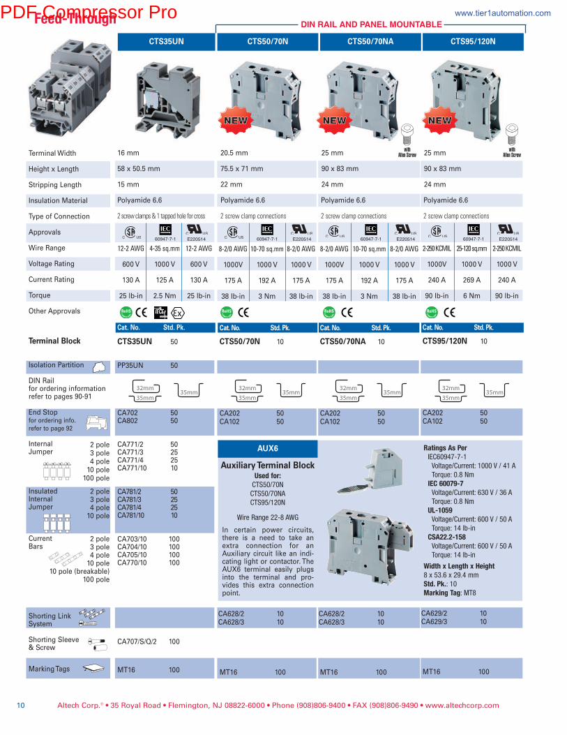
AUX6
Auxiliary Terminal BlockUsedfor:CTS50/70N
CTS50/70NA
CTS95/120N
Wire Range 22-8 AWG
In certain power circuits,there is a need to take anextra connection for anAuxiliary circuit like an indi-cating light or contactor. TheAUX6 terminal easily plugsinto the terminal and pro-vides this extra connectionpoint.
RatingsAsPerIEC60947-7-1
Voltage/Current: 1000 V / 41 A
Torque: 0.8 Nm
IEC60079-7Voltage/Current: 630 V / 36 A
Torque: 0.8 Nm
UL-1059Voltage/Current: 600 V / 50 A
Torque: 14 lb-in
CSA22.2-158Voltage/Current: 600 V / 50 A
Torque: 14 lb-in
WidthxLengthxHeight8 x 53.6 x 29.4 mm
Std.Pk.: 10MarkingTag: MT8
NEWNEW NEWNEW NEWNEW
DIN RAIL AND PANEL MOUNTABLE
withAllen Screw
withAllen Screw
PDF Compressor Pro www.tier1automation.com

Altech Corp.® • 35 Royal Road • Flemington, NJ 08822-6000 • Phone (908)806-9400 • FAX (908)806-9490 • www.altechcorp.com 11
HighVoltageTerminalBlocks
Terminal Width
Height x Length
Stripping Length
Insulation Material
Approvals
Wire Range
Voltage Rating
Current Rating
Torque
Other Approvals
Terminal Block
End Plate
Separator Plate
DIN Railfor ordering informationrefer to pages 90-91
End Stopfor ordering info.refer to page 92
InternalJumper
InsulatedInternalJumper
CurrentBars
Short Sleeve& Screw
Marking Tags
2 pole3 pole4 pole10 pole
2 pole3 pole4 pole10 pole
2 pole3 pole4 pole10 pole
6 mm 70.8 x 52 mm
12 mm
Polyamide 6.6
22-10AWG 0.2-4sq.mm 22-10AWG
1000 V 1000 V 1000 V
35 A 32 A 35 A
7 lb-in 0.5 Nm 7 lb-in
Cat.No. Std.Pk. CHV4U 100
EPUSC 50
SP2.5/4UN 50
CA702 50
CA802 50
CA623/2 100 CA623/3 100 CA623/4 100 CA623/10 10
CA643/2 100 CA643/3 100 CA643/4 100 CA643/10 10
CA703/1 100 CA704/1 100 CA705/1 100 CA732/10 100
CA608/S/Q 100
MT6 100
CHV4U
8 mm 70.8 x 52 mm
14 mm
Polyamide 6.6
22-8AWG 0.2-6sq.mm 22-8AWG
1000 V 1000 V 1000 V
50 A 41 A 50 A
14 lb-in 0.8 Nm 14 lb-in
Cat.No. Std.Pk. CHV6U 100
EPUSC 50
SP2.5/4UN 50
CA702 50
CA802 50
CA624/2 100 CA624/3 100 CA624/4 100 CA624/10 10
CA644/2 100 CA644/3 100 CA644/4 100 CA644/10 10
CA703/2 100 CA704/2 100 CA705/2 100 CA733/10 100
CA609/S/Q 100
MT8 100
CHV6U
10 mm 70.8 x 52 mm
14 mm
Polyamide 6.6
20-6AWG 0.2-10sq.mm 22-6AWG
1000 V 1000 V 1000 V
65 A 57 A 65 A
14 lb-in 1.2 Nm 14 lb-in
Cat.No. Std.Pk. CHV10U 100
EPUSC 50
SP2.5/4UN 50
CA702 50
CA802 50
CA625/2 100 CA625/3 100 CA625/4 100 CA625/10 10
CA645/2 100 CA645/3 100 CA645/4 100 CA645/10 10
CA703/3 100 CA704/3 100 CA705/3 100 CA734/10 100
CA610/S/Q 100
MT10 100
CHV10UThe CHV series TerminalBlocks have been speciallydesigned for high voltageuse, such as in solar appli-cations.
A specially designed flexi-ble foot enables easymounting and dismount-ing from the mounting railwith the help of a screwdriver. These TerminalBlocks have marker hold-ing recesses to acceptmarking tags for circuitidentification. Cross con-nection can be achievedwith the aid of shortinglinks / sleeves & screws.
E220514 E220514 E220514
NEWNEW NEWNEW NEWNEW
60947-7-1 60947-7-1 60947-7-1
PDF Compressor Pro www.tier1automation.com
Altech Corp.® • 35 Royal Road • Flemington, NJ 08822-6000 • Phone (908)806-9400 • FAX (908)806-9490 • www.altechcorp.com12
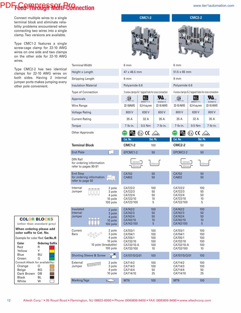
Feed-ThroughMulti-ConnectionCMC1-2 CMC2-2Connect multiple wires to a single
terminal block and eliminate relia-
bility problems encountered when
connecting two wires into a single
clamp. Two versions are available.
Type CMC1-2 features a single
screw-cage clamp for 22-10 AWG
wires on one side and two clamps
on the other side for 22-10 AWG
wires.
Type CMC2-2 has two identical
clamps for 22-10 AWG wires on
both sides. Having 2 internal
jumper ports makes jumping every
other pole convenient.
6 mm
51.5 x 65 mm
9 mm
Polyamide 6.6
4screwclamps&2tappedholesforcrossconnection
22-10AWG 0.2-4sq.mm 22-10AWG
600 V 630 V 600 V
35 A 32 A 35 A
7 lb-in. 0.5 Nm 7 lb-in.
Cat.No. Std.Pk.
CMC2-2 50
EPCMC2-2 50
CA702 50CA802 50
CA722/2 100CA722/3 50CA722/4 50CA722/10 10CA722/100 5
CA742/2 100CA742/3 50CA742/4 50CA742/10 10CA742/100 5
CA703/1 100CA704/1 100CA705/1 100CA732/10 100CA732/10-A 100CA732/100 10
CA707/S/Q/01 100
CA714/2 100CA714/3 100CA714/4 50CA714/10 25
MT6 100
Terminal Width
Height x Length
Stripping Length
Insulation Material
Type of Connection
Approvals
Wire Range
Voltage Rating
Current Rating
Torque
Other Approvals
Terminal Block
End Plate
DIN Railfor ordering informationrefer to pages 90-91
End Stopfor ordering informationrefer to page 92
InternalJumper
InsulatedInternalJumper
CurrentBars
Shorting Sleeve & Screw
ExternalJumper
Marking Tags
2 pole3 pole4 pole10 pole
100 pole
2 pole3 pole4 pole10 pole
100 pole
2 pole3 pole4 pole10 pole
10 pole (breakable)100 pole
2 pole3 pole4 pole10 pole
6 mm
47 x 46.5 mm
9 mm
Polyamide 6.6
3screwclamps&1tappedholeforcrossconnection
22-10AWG 0.2-4sq.mm 22-10AWG
600 V 630 V 600 V
35 A 32 A 35 A
7 lb-in. 0.5 Nm 7 lb-in.
Cat.No. Std.Pk.
CMC1-2 100
EPCMC1-2 50
CA702 50CA802 50
CA722/2 100CA722/3 50CA722/4 50CA722/10 10CA722/100 5
CA742/2 100CA742/3 50CA742/4 50CA742/10 10CA742/100 5
CA703/1 100CA704/1 100CA705/1 100CA732/10 100CA732/10-A 100CA732/100 10
CA707/S/Q/01 100
CA714/2 100CA714/3 100CA714/4 50CA714/10 25
MT6 100
E220514 E22051460947-7-1 60947-7-1
COLOR BLOCKS(otherthanstandardgrey)
When ordering please addcolor suffix to Cat. No.
ExampleforcolorRed:Cat.No./R
Color OrderingSuffixRed R
Yellow Y
Blue BU
Green G
ConsultAltechforavailability:Orange O
Beige BG
Dark Brown DB
Black BL
White W
PDF Compressor Pro www.tier1automation.com
Altech Corp.® • 35 Royal Road • Flemington, NJ 08822-6000 • Phone (908)806-9400 • FAX (908)806-9490 • www.altechcorp.com 13
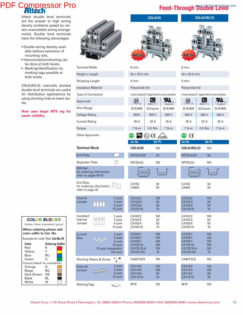
CDL4UN CDL4UN(I.S)Altech double level terminals
are the answer to high wiring
density problems posed by cer-
tain unavoidable wiring arrange-
ments. Double level terminals
have the following advantages:
• Double wiring density avail-
able without extension of
mounting rails.
• Interconnection/shorting can
be done at both levels.
• Marking/identification by
marking tags possible at
both levels.
CDL4UN(I.S) internally shorted
double level terminals are useful
for distribution applications by
using shorting links at lower lev-
els.
Now uses larger MT6 tag foreasier visibility.
6 mm
54 x 55.5 mm
9 mm
Polyamide 6.6
4screwclamps&2tappedholesforcrossconnection
22-10AWG 0.2-4sq.mm 22-10AWG
600V 800 V 600 V
35 A 32 A 35 A
7 lb-in 0.5 Nm 7 lb-in
Cat.No. Std.Pk.
CDL4UN 100
EPCDL4UN 50
SPCDL4U 100
CA702 50CA802 50
CA722/2 100CA722/3 50CA722/4 50CA722/10 10
CA742/2 100CA742/3 50CA742/4 50CA742/10 10
CA703/1 100CA704/1 100CA705/1 100CA732/10 100CA732/10-A 100CA732/100 10
CA607/S/Q 100
CA714/2 100CA714/3 100CA714/4 50CA714/10 25
MT6 100
6 mm
54 x 55.5 mm
9 mm
Polyamide 6.6
4screwclamps&1tappedholeforcrossconnection
22-10AWG 0.2-4sq.mm 22-10AWG
600 V 800 V 600 V
35 A 32 A 35 A
7 lb-in 0.5 Nm 7 lb-in
Cat.No. Std.Pk.
CDL4UN(I.S) 100
EPCDL4UN 50
SPCDL4U 100
CA702 50CA802 50
CA722/2 100CA722/3 50CA722/4 50CA722/10 10
CA742/2 100CA742/3 50CA742/4 50CA742/10 10
CA703/1 100CA704/1 100CA705/1 100CA732/10 100CA732/10-A 100CA732/100 10
CA607/S/Q 100
CA714/2 100CA714/3 100CA714/4 50CA714/10 25
MT6 100
E220514 E220514
Terminal Width
Height x Length
Stripping Length
Insulation Material
Type of Connection
Approvals
Wire Range
Voltage Rating
Current Rating
Torque
Other Approvals
Terminal Block
End Plate
Separator Plate
DIN Railfor ordering informationrefer to pages 90-91
End Stopfor ordering informationrefer to page 92
InternalJumper
InsulatedInternalJumper
CurrentBars
Shorting Sleeve & Screw
ExternalJumper
Marking Tags
2 pole3 pole4 pole10 pole
2 pole3 pole4 pole10 pole
2 pole3 pole4 pole10 pole
10 pole (breakable)100 pole
2 pole3 pole4 pole10 pole
Feed-ThroughDoubleLevel
60947-7-1 60947-7-1
NEWNEW NEWNEW
COLOR BLOCKS(otherthanstandardgrey)
When ordering please addcolor suffix to Cat. No.
ExampleforcolorRed:Cat.No./R
Color OrderingSuffixRed R
Yellow Y
Blue BU
Green G
ConsultAltechforavailability:Orange O
Beige BG
Dark Brown DB
Black BL
White W
PDF Compressor Pro www.tier1automation.com
Altech Corp.® • 35 Royal Road • Flemington, NJ 08822-6000 • Phone (908)806-9400 • FAX (908)806-9490 • www.altechcorp.com
Feed-ThroughOffsetDoubleLevel
14
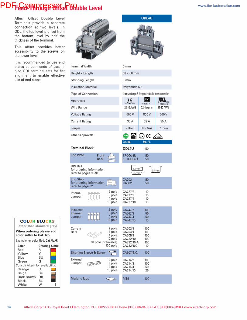
ODL4UAltech Offset Double Level
Terminals provide a separate
connection at two levels. In
ODL, the top level is offset from
the bottom level by half the
thickness of the terminal.
This offset provides better
accessibility to the screws on
the lower level.
It is recommended to use end
plates at both ends of assem-
bled ODL terminal sets for flat
alignment to enable effective
use of end stops.
6 mm
63 x 68 mm
9 mm
Polyamide 6.6
4screwclamps&2tappedholesforcrossconnection
22-10AWG 0.2-4sq.mm 22-10AWG
600 V 800 V 600 V
35 A 32 A 35 A
7 lb-in 0.5 Nm 7 lb-in
Cat.No. Std.Pk.
ODL4U 50
EPODL4U 50EP1ODL4U 50
CA702 50CA802 50
CA727/2 10CA727/3 10CA727/4 10CA727/10 10
CA747/2 100CA747/3 50CA747/4 50CA747/10 10
CA703/1 100CA704/1 100CA705/1 100CA732/10 100CA732/10-A 100CA732/100 10
CA607/S/Q 100
CA714/2 100CA714/3 100CA714/4 50CA714/10 25
MT6 100
Terminal Width
Height x Length
Stripping Length
Insulation Material
Type of Connection
Approvals
Wire Range
Voltage Rating
Current Rating
Torque
Other Approvals
Terminal Block
End Plate
DIN Railfor ordering informationrefer to pages 90-91
End Stopfor ordering informationrefer to page 92
InternalJumper
InsulatedInternalJumper
CurrentBars
Shorting Sleeve & Screw
ExternalJumper
Marking Tags
2 pole3 pole4 pole10 pole
2 pole3 pole4 pole10 pole
2 pole3 pole4 pole10 pole
10 pole (breakable)100 pole
2 pole3 pole4 pole10 pole
FrontBack
E22051460947-7-1
COLOR BLOCKS(otherthanstandardgrey)
When ordering please addcolor suffix to Cat. No.
ExampleforcolorRed:Cat.No./R
Color OrderingSuffixRed R
Yellow Y
Blue BU
Green G
ConsultAltechforavailability:Orange O
Beige BG
Dark Brown DB
Black BL
White W
PDF Compressor Pro www.tier1automation.com
Altech Corp.® • 35 Royal Road • Flemington, NJ 08822-6000 • Phone (908)806-9400 • FAX (908)806-9490 • www.altechcorp.com 15
CTL2.5U-H CTL2.5U
6 mm
67 x 61 mm
9 mm
Polyamide 6.6
4Screwclamps&3tappedholesforcrossconnect.
22-12AWG 0.2-2.5sq.mm 22-12AWG
300 V 500 V 300 V
25 A 24 A 25 A
4.5 lb-in 0.4 Nm 4.5 lb-in
Cat.No. Std.Pk. CTL2.5U-H 50
EPCTL2.5U-H 50
CA202 50CA702 50CA802 50
CA722/2 100CA722/3 50CA722/4 50CA722/10 10CA722/100 5
CA703/1 100CA704/1 100CA705/1 100CA732/10 100CA732/10-A 100CA732/100 10
CA707/S/Q/01 100
CA715/2 100CA715/3 100CA715/4 100CA715/10 50
MT2 100
6 mm
67 x 84 mm
9 mm
Polyamide 6.6
6Screwclamps&3tappedholesforcrossconnect.
22-12AWG 0.2-2.5sq.mm 22-12AWG
300 V 500 V 300 V
25 A 24 A 25 A
4.5 lb-in 0.4 Nm 4.5 lb-in
Cat.No. Std.Pk. CTL2.5U 50
EPCTL2.5U 50
CA202 50CA702 50CA802 50
CA722/2 100 CA722/3 50 CA722/4 50 CA722/10 10CA722/100 5
CA703/1 100CA704/1 100CA705/1 100CA732/10 100CA732/10-A 100CA732/100 10
CA707/S/Q/01 100
CA715/2 100CA715/3 100CA715/4 100CA715/10 50
MT2 100
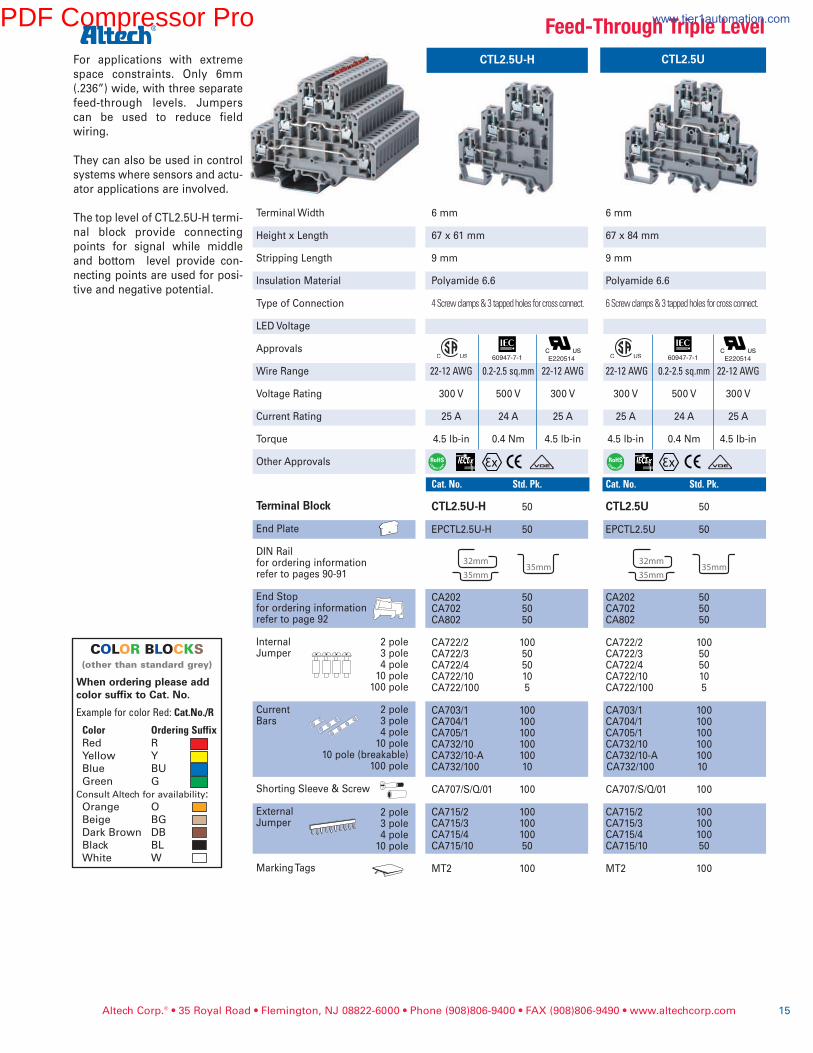
For applications with extreme
space constraints. Only 6mm
(.236”) wide, with three separate
feed-through levels. Jumpers
can be used to reduce field
wiring.
They can also be used in control
systems where sensors and actu-
ator applications are involved.
The top level of CTL2.5U-H termi-
nal block provide connecting
points for signal while middle
and bottom level provide con-
necting points are used for posi-
tive and negative potential.
E220514 E220514
Terminal Width
Height x Length
Stripping Length
Insulation Material
Type of Connection
LED Voltage
Approvals
Wire Range
Voltage Rating
Current Rating
Torque
Other Approvals
Terminal Block
End Plate
DIN Railfor ordering informationrefer to pages 90-91
End Stopfor ordering informationrefer to page 92
InternalJumper
CurrentBars
Shorting Sleeve & Screw
ExternalJumper
Marking Tags
2 pole3 pole4 pole10 pole
100 pole
2 pole3 pole4 pole10 pole
10 pole (breakable)100 pole
2 pole3 pole4 pole10 pole
Feed-ThroughTripleLevel
COLOR BLOCKS(otherthanstandardgrey)
When ordering please addcolor suffix to Cat. No.
ExampleforcolorRed:Cat.No./R
Color OrderingSuffixRed R
Yellow Y
Blue BU
Green G
ConsultAltechforavailability:Orange O
Beige BG
Dark Brown DB
Black BL
White W
60947-7-1 60947-7-1
PDF Compressor Pro www.tier1automation.com

Altech Corp.® • 35 Royal Road • Flemington, NJ 08822-6000 • Phone (908)806-9400 • FAX (908)806-9490 • www.altechcorp.com16
Feed-ThroughTripleLevel
CTL2.5U-H(L)* CTL2.5U(L)*
6 mm
67 x 61 mm
9 mm
Polyamide 6.6
4Screwclamps&2tappedholesforcrossconnect.
12V, 24V, 48V, 110V DC
22-12AWG 0.2-2.5sq.mm 22-12AWG
300 V 500 V 300 V
25 A 24 A 25 A
4.5 lb-in 0.4 Nm 4.5 lb-in
Cat.No. Std.Pk. CTL2.5U-H(L)* 50
EPCTL2.5U-H 50
CA202 50CA702 50CA802 50
CA722/2 100CA722/3 50CA722/4 50CA722/10 10CA722/100 5
CA703/1 100CA704/1 100CA705/1 100CA732/10 100CA732/10-A 100CA732/100 10
CA707/S/Q/01 100
CA715/2 100CA715/3 100CA715/4 100CA715/10 50
MT2 100
6 mm
67 x 84 mm
9 mm
Polyamide 6.6
6Screwclamps&2tappedholesforcrossconnect.
12V, 24V, 48V, 110V DC
22-12AWG 0.2-2.5sq.mm22-12AWG
300 V 500 V 300 V
25 A 24 A 25 A
4.5 lb-in 0.4 Nm 4.5 lb-in
Cat.No. Std.Pk. CTL2.5U(L)* 50
EPCTL2.5U 50
CA202 50CA702 50CA802 50
CA722/2 100CA722/3 50CA722/4 50CA722/10 10CA722/100 5
CA703/1 100CA704/1 100CA705/1 100CA732/10 100CA732/10-A 100CA732/100 10
CA707/S/Q/01 100
CA715/2 100CA715/3 100CA715/4 100CA715/10 50
MT2 100
+ve
-ve
+ve
-ve
E220514
Circuit Diagrams
* Add required voltage to part number as suffix; i.e.CTL2.5U(L)/24for24VDC
Idealforsensorapplications.SeeAltech’sInductive
ProximitySensorcatalogfororderinginformation.
Terminal Width
Height x Length
Stripping Length
Insulation Material
Type of Connection
LED Voltage
Approvals
Wire Range
Voltage Rating
Current Rating
Torque
Other Approvals
Terminal Block
End Plate
DIN Railfor ordering informationrefer to pages 90-91
End Stopfor ordering informationrefer to page 92
InternalJumper
CurrentBars
Shorting Sleeve & Screw
ExternalJumper
Marking Tags
2 pole3 pole4 pole10 pole
100 pole
2 pole3 pole4 pole10 pole
10 pole (breakable)100 pole
2 pole3 pole4 pole10 pole
E22051460947-7-1 60947-7-1
In applications where switching
indication is required, choice of
CTL2.5UH(L) and CTL2.5U(L) ter-
minal blocks with built-in elec-
tronic components are available.
PDF Compressor Pro www.tier1automation.com
Altech Corp.® • 35 Royal Road • Flemington, NJ 08822-6000 • Phone (908)806-9400 • FAX (908)806-9490 • www.altechcorp.com 17
Double&TripleLevelBlockswithGround
CDLG2.5 CTLG2.5
6 mm
50 x 71 mm
9 mm
Polyamide 6.6
5Screwclamps&2tappedholesforcrossconnect.
24-12AWG 0.25-4mm24-12AWG
300 V 500 V 300 V
24 A 24 A 24 A
4.5 lb-in 0.4 Nm 4.5 lb-in
Cat.No. Std.Pk. CDLG2.5 50
EPCDLG2.5 50
CA202 50CA702 50CA802 50
CA627/2 100CA627/3 50CA627/4 50CA627/10 10
CA647/2 100CA647/3 50CA647/4 50CA647/10 10
CA703/1 100CA704/1 100CA705/1 100CA732/10 100CA732/10-A 100CA732/100 10
CA611/S/Q 100
CA715/2 100CA715/3 100CA715/4 100CA715/10 50
MT2G 100
6 mm
62 x 87.5 mm
9 mm
Polyamide 6.6
7Screwclamps&1tappedholeforcrossconnect.
24-12AWG 0.25-4mm 24-12AWG
300 V 440 V 600 V
25 A 24 A 24 A
4.5 lb-in 0.4 Nm 4.5 lb-in
Cat.No. Std.Pk. CTLG2.5 50
EPCTLG2.5 50
CA202 50CA702 50CA802 50
CA627/2 100 CA627/3 50 CA627/4 50 CA627/10 10
CA647/2 100CA647/3 50CA647/4 50CA647/10 10
CA703/1 100CA704/1 100CA705/1 100CA732/10 100CA732/10-A 100CA732/100 10
CA611/S/Q 100
CA715/2 100CA715/3 100CA715/4 100CA715/10 50
MT2G 100
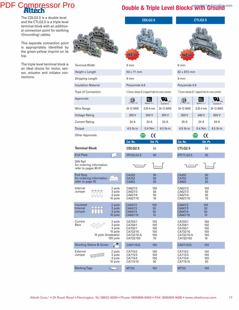
The CDLG2.5 is a double level
and the CTLG2.5 is a triple level
terminal block with an addition-
al connection point for earthing
(Grounding) cables.
This separate connection point
is appropriately identified by
the green-yellow imprint on its
top.
The triple level terminal block is
an ideal choice for motor, sen-
sor, actuator and initiator con-
nections.
E220514 E220514
Terminal Width
Height x Length
Stripping Length
Insulation Material
Type of Connection
Approvals
Wire Range
Voltage Rating
Current Rating
Torque
Other Approvals
Terminal Block
End Plate
DIN Railfor ordering informationrefer to pages 90-91
End Stopfor ordering informationrefer to page 92
InternalJumper
InsulatedInternalJumper
CurrentBars
Shorting Sleeve & Screw
ExternalJumper
Marking Tags
2 pole3 pole4 pole10 pole
2 pole3 pole4 pole10 pole
2 pole3 pole4 pole10 pole
10 pole (breakable)100 pole
2 pole3 pole4 pole10 pole
NEWNEW NEWNEW
60947-7-1 60947-7-1
PDF Compressor Pro www.tier1automation.com

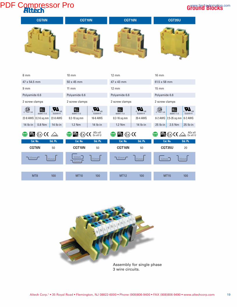
CGT4N
6 mm 45.4 x 54.2 mm
8 mm
Polyamide 6.6
2 screw clamps
22-10AWG0.2-4sq.mm22-10AWG
7 lb-in 0.5 Nm 7 lb-in
Cat.No. Std.Pk. CGT4N 50
MT6 100
CGT4UUse ground blocks instead of
grounding studs and wire
lugs to terminate ground
wires, saving installation and
wiring time.
They offer:
• High density
• Screw-cage clamp
• Special clamping foot
• Polyamide 6.6
• Color: green/yellow
Ground blocks clamp
mechanically onto the DIN
Rail by tightening the center
mounting screw, making a
reliable electrical connection
between the cage clamp ter-
minals and the DIN Rail. The
rail serves as a busbar and
automatically distributes
ground potential to all other
ground terminals on the
same rail.
Ground blocks can also be
used as end stops, preventing
other terminal blocks and
components from moving lat-
erally on the DIN Rail.
They are supplied with a
standard green/yellow hous-
ing for easy identification and
accept standard marking
tags.
CGT4U and CGT35U can be
mounted on both DIN 32mm
and DIN 35mm rails.
CGT4N, CGT6N, CGT10N and
CGT16N can be mounted on
35mm DIN rail and have the
same top outer profile as the
feed through blocks (CTS4U-
N, CTS2.5U-N, CTS6U,
CTS10U and CTS16U).
Terminal Width
Height x Length
Stripping Length
Insulation Material
Type of Connection
Approvals
Wire Range
Torque
Other Approvals
Terminal Block
DIN Railfor ordering informationrefer to pages 90-91
End Plate
Marking Tags(MT Type)
6 mm
48 x 43 mm
8 mm
Polyamide 6.6
2 screw clamps
22-10AWG 0.2-4sq.mm 22-10AWG
7 lb-in 0.5 Nm 7 lb-in
Cat.No. Std.Pk. CGT4U 50
EPCGT4U 50
MT6 100
E220514 E220514
Altech Corp.® • 35 Royal Road • Flemington, NJ 08822-6000 • Phone (908)806-9400 • FAX (908)806-9490 • www.altechcorp.com18
AExeIIExeIIU
GroundBlocks
60947-7-2 60947-7-2
PDF Compressor Pro www.tier1automation.com
Altech Corp.® • 35 Royal Road • Flemington, NJ 08822-6000 • Phone (908)806-9400 • FAX (908)806-9490 • www.altechcorp.com 19
Assemblyforsinglephase3wirecircuits.
GroundBlocks
CGT10N
10 mm
50 x 45 mm
11 mm
Polyamide 6.6
2 screw clamps
0.2-10sq.mm 16-6AWG
1.2 Nm 14 lb-in
Cat.No. Std.Pk. CGT10N 50
MT10 100
CGT16N
12 mm
47 x 43 mm
12 mm
Polyamide 6.6
2 screw clamps
0.2-16sq.mm 20-4AWG
1.2 Nm 14 lb-in
Cat.No. Std.Pk. CGT16N 50
MT12 100
E220514
CGT35U
16 mm
61.5 x 58 mm
15 mm
Polyamide 6.6
2 screw clamps
8-2AWG 2.5-35sq.mm 8-2AWG
25 lb-in 2.5 Nm 25 lb-in
Cat.No. Std.Pk. CGT35U 20
MT15 100
E220514
AExeIIExeIIU
AExeIIExeIIU
E220514
CGT6N
8 mm
47 x 54.5 mm
9 mm
Polyamide 6.6
2 screw clamps
22-8AWG 0.2-6sq.mm 22-8AWG
14 lb-in 0.8 Nm 14 lb-in
Cat.No. Std.Pk. CGT6N 50
MT8 100
E22051460947-7-2 60947-7-2 60947-7-2 60947-7-2
PDF Compressor Pro www.tier1automation.com
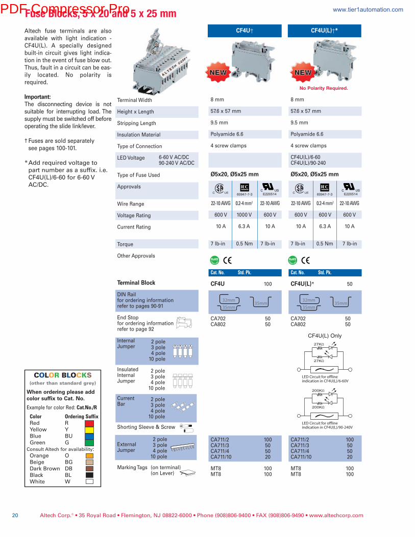
Altech fuse terminals are also
available with light indication -
CF4U(L). A specially designed
built-in circuit gives light indica-
tion in the event of fuse blow out.
Thus, fault in a circuit can be eas-
ily located. No polarity is
required.
Important:The disconnecting device is not
suitable for interrupting load. The
supply must be switched off before
operating the slide link/lever.
† Fuses are sold separately
see pages 100-101.
*Add required voltage to
part number as a suffix. i.e.
CF4U(L)/6-60 for 6-60 V
AC/DC.
Terminal Width
Height x Length
Stripping Length
Insulation Material
Type of Connection
LED Voltage
Type of Fuse Used
Approvals
Wire Range
Voltage Rating
Current Rating
Torque
Other Approvals
Terminal Block
DIN Railfor ordering informationrefer to pages 90-91
End Stopfor ordering informationrefer to page 92
InternalJumper
InsulatedInternalJumper
CurrentBar
Shorting Sleeve & Screw
ExternalJumper
Marking Tags (on terminal)(on Lever)
2 pole3 pole4 pole10 pole
Altech Corp.® • 35 Royal Road • Flemington, NJ 08822-6000 • Phone (908)806-9400 • FAX (908)806-9490 • www.altechcorp.com20
FuseBlocks,5x20and5x25mm
2 pole3 pole4 pole10 pole
2 pole3 pole4 pole10 pole
2 pole3 pole4 pole10 pole
CF4U†
8 mm
57.6 x 57 mm
9.5 mm
Polyamide 6.6
4 screw clamps
Ø5x20, Ø5x25 mm
22-10AWG 0.2-4mm2 22-10AWG
600 V 1000 V 600 V
10 A 6.3 A 10 A
7 lb-in 0.5 Nm 7 lb-in
Cat.No. Std.Pk.
CF4U 100
CA702 50CA802 50
CA711/2 100CA711/3 50CA711/4 50CA711/10 20
MT8 100MT8 100
E220514
CF4U(L)†*
8 mm
57.6 x 57 mm
9.5 mm
Polyamide 6.6
4 screw clamps
CF4U(L)/6-60CF4U(L)/90-240
Ø5x20, Ø5x25 mm
22-10AWG 0.2-4mm2 22-10AWG
600 V 600 V 600 V
10 A 6.3 A 10 A
7 lb-in 0.5 Nm 7 lb-in
Cat.No. Std.Pk.
CF4U(L)* 50
CA702 50CA802 50
CA711/2 100CA711/3 50CA711/4 50CA711/10 20
MT8 100MT8 100
6-60 V AC/DC90-240 V AC/DC
E220514
27KΩ
27KΩ
200KΩ
200KΩ
LED Circuit for o�ineindication in CF4U(L)/6-60V
LED Circuit for o�ineindication in CF4U(L)/90-240V
CF4U(L) Only
NEWNEW NEWNEW
COLOR BLOCKS(otherthanstandardgrey)
When ordering please addcolor suffix to Cat. No.
ExampleforcolorRed:Cat.No./R
Color OrderingSuffixRed R
Yellow Y
Blue BU
Green G
ConsultAltechforavailability:Orange O
Beige BG
Dark Brown DB
Black BL
White W
NoPolarityRequired.
60947-7-3 60947-7-3
PDF Compressor Pro www.tier1automation.com

Altech Corp.® • 35 Royal Road • Flemington, NJ 08822-6000 • Phone (908)806-9400 • FAX (908)806-9490 • www.altechcorp.com 21
FuseBlocks,5x20and5x25mm
Terminal Width
Height x Length
Stripping Length
Insulation Material
Type of Connection
LED Voltage
Type of Fuse Used
Approvals
Wire Range
Voltage Rating
Current Rating
Torque
Other Approvals
Terminal Block
End Plate
DIN Railfor ordering informationrefer to pages 90-91
End Stopfor ordering informationrefer to page 92
InternalJumper
InsulatedInternalJumper
CurrentBar
Shorting Sleeve & Screw
ExternalJumper
Marking Tags (on terminal)(on lever)
2 pole3 pole4 pole10 pole
2 pole3 pole4 pole10 pole
2 pole3 pole4 pole10 pole
2 pole3 pole4 pole10 pole
Top Level
DDFL4U - Double Level Fuse
Terminal with fuse link on the top
level has a separate feed through
terminal at the lower level. This
eliminates use of an additional feed
through terminal.
In DDFL4U(E), specially designed
built in circuit gives light indication
in the event of a fuse blow out at
the top level. The terminal provides
separate feed through connection
possibility at the lower level.
Important:The disconnecting device is not suit-
able for interrupting load. The supply
must be switched off before operat-
ing the slide link/lever.
† Fuses are sold separately
Altech, see pages 100-101.
* Add required voltage to part
number as suffix, i.e.
DDFL4U(E)/24 for 24V AC/DC
COLOR BLOCKS(otherthanstandardgrey)
When ordering please addcolor suffix to Cat. No.
ExampleforcolorRed:Cat.No./R
Color OrderingSuffixRed R
Yellow Y
Blue BU
Green G
ConsultAltechforavailability:Orange O
Beige BG
Dark Brown DB
Black BL
White W
†Fusenotincluded. †Fusenotincluded.
24VAC/DC,48VAC/DC,110VAC/DC,220VAC/DC,440VAC
DDFL4U
8 mm
66 x 88 mm
9.5 mm
Polyamide 6.6
Ø5x20, Ø5x25 mm
22-10AWG 0.2-4mm2 22-10AWG
600 V 800 V 600 V
6.3 A 6.3 A 6.3 A35 A 32 A 35 A
7 lb-in 0.5 N 7 lb-in
Cat.No. Std.Pk.
DDFL4U 20
EPDDFL4U 20
CA702 50CA802 50CA202 50
CA729/2 100CA729/3 50CA729/4 50CA729/10 10
CA749/2 100CA749/3 50CA749/4 50CA749/10 10
CA703/6 100CA704/6 100CA705/6 100CA737/10 100
CA707/S/Q/3 100
CA711/2 100CA711/3 100CA711/4 50CA711/10 25
MT8 100MT2 100
DDFL4U(E)*
8 mm
66 x 88 mm
9.5 mm
Polyamide 6.6
Ø5x20, Ø5x25 mm
22-10AWG 0.2-4mm2 22-10AWG
600 V 800 V 600 V
6.3 A 6.3 A 6.3 A35 A 32 A 35 A
7 lb-in 0.5 Nm 7 lb-in
Cat.No. Std.Pk.
DDFL4U(E)* 20
EPDDFL4U 20
CA702 50CA802 50CA202 50
CA729/2 100CA729/3 50CA729/4 50CA729/10 10
CA749/2 100CA749/3 50CA749/4 50CA749/10 10
CA703/6 100CA704/6 100CA705/6 100CA737/10 100
CA707/S/Q/3 100
CA711/2 100CA711/3 100CA711/4 50CA711/10 25
MT8 100MT2 100
E220514E22051460947-7-3 60947-7-3
4screwclamps&1tappedholeforcrossconnection
4screwclamps&1tappedholeforcrossconnection
PDF Compressor Pro www.tier1automation.com
Terminal Width
Height x Length
Stripping Length
Insulation Material
Type of Connection
LED Voltage
Type of Fuse Used
Approvals
Wire Range
Voltage Rating
Current Rating
Torque
Other Approvals
Terminal Block
End Plate
DIN Railfor ordering informationrefer to pages 90-91
End Stopfor ordering informationrefer to page 92
InternalJumper
InsulatedInternalJumper
CurrentBar
Shorting Sleeve & Screw
ExternalJumper
Marking Tags (on terminal)(on lever)
2 pole3 pole4 pole10 pole
2 pole3 pole4 pole10 pole
2 pole3 pole4 pole10 pole
2 pole3 pole4 pole10 pole
Top Level
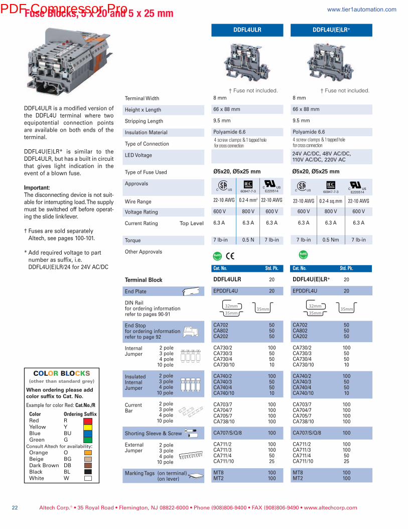
DDFL4ULR is a modified version of
the DDFL4U terminal where two
equipotential connection points
are available on both ends of the
terminal.
DDFL4U(E)LR* is similar to the
DDFL4ULR, but has a built in circuit
that gives light indication in the
event of a blown fuse.
Important:The disconnecting device is not suit-
able for interrupting load. The supply
must be switched off before operat-
ing the slide link/lever.
† Fuses are sold separately
Altech, see pages 100-101.
* Add required voltage to part
number as suffix, i.e.
DDFL4U(E)LR/24 for 24V AC/DC
Altech Corp.® • 35 Royal Road • Flemington, NJ 08822-6000 • Phone (908)806-9400 • FAX (908)806-9490 • www.altechcorp.com22
8 mm
66 x 88 mm
9.5 mm
Polyamide 6.6
Ø5x20, Ø5x25 mm
22-10AWG 0.2-4sq.mm 22-10AWG
600 V 800 V 600 V
6.3 A 6.3 A 6.3 A
7 lb-in 0.5 Nm 7 lb-in
Cat.No. Std.Pk.
DDFL4U(E)LR* 20
EPDDFL4U 20
CA702 50CA802 50CA202 50
CA730/2 100CA730/3 50CA730/4 50CA730/10 10
CA740/2 100CA740/3 50CA740/4 50CA740/10 10
CA703/7 100CA704/7 100CA705/7 100CA738/10 100
CA707/S/Q/8 100
CA711/2 100CA711/3 100CA711/4 50CA711/10 25
MT8 100MT2 100
24V AC/DC, 48V AC/DC,110V AC/DC, 220V AC
DDFL4U(E)LR*
E220514
†Fusenotincluded.
FuseBlocks,5x20and5x25mm
COLOR BLOCKS(otherthanstandardgrey)
When ordering please addcolor suffix to Cat. No.
ExampleforcolorRed:Cat.No./R
Color OrderingSuffixRed R
Yellow Y
Blue BU
Green G
ConsultAltechforavailability:Orange O
Beige BG
Dark Brown DB
Black BL
White W
†Fusenotincluded.
DDFL4ULR
8 mm
66 x 88 mm
9.5 mm
Polyamide 6.6
Ø5x20, Ø5x25 mm
22-10AWG 0.2-4mm2 22-10AWG
600 V 800 V 600 V
6.3 A 6.3 A 6.3 A
7 lb-in 0.5 N 7 lb-in
Cat.No. Std.Pk.
DDFL4ULR 20
EPDDFL4U 20
CA702 50CA802 50CA202 50
CA730/2 100CA730/3 50CA730/4 50CA730/10 10
CA740/2 100CA740/3 50CA740/4 50CA740/10 10
CA703/7 100CA704/7 100CA705/7 100CA738/10 100
CA707/S/Q/8 100
CA711/2 100CA711/3 100CA711/4 50CA711/10 25
MT8 100MT2 100
E22051460947-7-3 60947-7-3
4screwclamps&1tappedholeforcrossconnection
4screwclamps&1tappedholeforcrossconnection
PDF Compressor Pro www.tier1automation.com
Altech Corp.® • 35 Royal Road • Flemington, NJ 08822-6000 • Phone (908)806-9400 • FAX (908)806-9490 • www.altechcorp.com 23
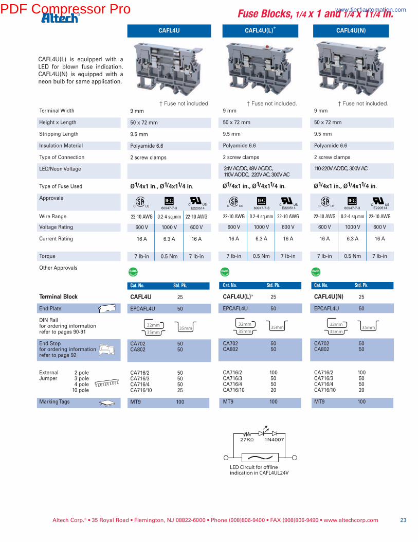
Fuse Blocks, 1/4 x 1 and 1/4 x 11/4 in.
Terminal Width
Height x Length
Stripping Length
Insulation Material
Type of Connection
LED/Neon Voltage
Type of Fuse Used
Approvals
Wire Range
Voltage Rating
Current Rating
Torque
Other Approvals
Terminal Block
End Plate
DIN Railfor ordering informationrefer to pages 90-91
End Stopfor ordering informationrefer to page 92
ExternalJumper
Marking Tags
2 pole3 pole4 pole10 pole
CAFL4U
9 mm
50 x 72 mm
9.5 mm
Polyamide 6.6
2 screw clamps
Ø1/4x1 in., Ø1/4x11/4 in.
22-10 AWG 0.2-4 sq.mm 22-10 AWG
600 V 1000 V 600 V
16 A 6.3 A 16 A
7 lb-in 0.5 Nm 7 lb-in
Cat. No. Std. Pk.
CAFL4U 25
EPCAFL4U 50
CA702 50CA802 50
CA716/2 50CA716/3 50CA716/4 50CA716/10 25
MT9 100
CAFL4U(L)* CAFL4U(N)
9 mm
50 x 72 mm
9.5 mm
Polyamide 6.6
2 screw clamps
Ø1/4x1 in., Ø1/4x11/4 in.
22-10 AWG 0.2-4 sq.mm 22-10 AWG
600 V 1000 V 600 V
16 A 6.3 A 16 A
7 lb-in 0.5 Nm 7 lb-in
Cat. No. Std. Pk.
CAFL4U(L)* 25
EPCAFL4U 50
CA702 50CA802 50
CA716/2 100CA716/3 50CA716/4 50CA716/10 20
MT9 100
9 mm
50 x 72 mm
9.5 mm
Polyamide 6.6
2 screw clamps
Ø1/4x1 in., Ø1/4x11/4 in.
22-10 AWG 0.2-4 sq.mm 22-10 AWG
600 V 1000 V 600 V
16 A 6.3 A 16 A
7 lb-in 0.5 Nm 7 lb-in
Cat. No. Std. Pk.
CAFL4U(N) 25
EPCAFL4U 50
CA702 50CA802 50
CA716/2 100CA716/3 50CA716/4 50CA716/10 20
MT9 100
24V AC/DC, 48V AC/DC,110V AC/DC, 220V AC, 300V AC
110-220V AC/DC, 300V AC
E220514 E220514 E220514
† Fuse not included. † Fuse not included. † Fuse not included.
CAFL4U(L) is equipped with a
LED for blown fuse indication.
CAFL4U(N) is equipped with a
neon bulb for same application.
60947-7-3 60947-7-3 60947-7-3
27KΩ 1N4007
LED Circuit for o�ine
indication in CAFL4UL24V
PDF Compressor Pro www.tier1automation.com
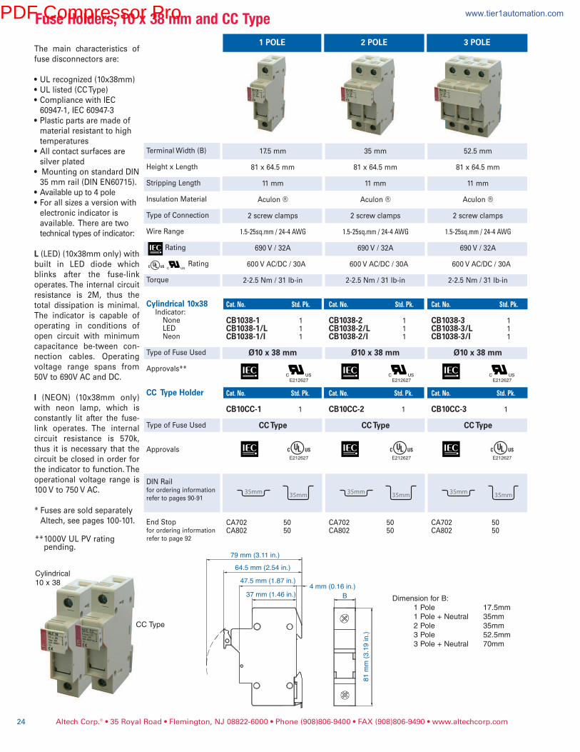
1 POLE 2 POLE 3 POLEThe main characteristics of
fuse disconnectors are:
• UL recognized (10x38mm)
• UL listed (CC Type)
• Compliance with IEC
60947-1, IEC 60947-3
• Plastic parts are made of
material resistant to high
temperatures
• All contact surfaces are
silver plated
• Mounting on standard DIN
35 mm rail (DIN EN60715).
• Available up to 4 pole
• For all sizes a version with
electronic indicator is
available. There are two
technical types of indicator:
L (LED) (10x38mm only) with
built in LED diode which
blinks after the fuse-link
operates. The internal circuit
resistance is 2M, thus the
total dissipation is minimal.
The indicator is capable of
operating in conditions of
open circuit with minimum
capacitance be-tween con-
nection cables. Operating
voltage range spans from
50V to 690V AC and DC.
I (NEON) (10x38mm only)
with neon lamp, which is
constantly lit after the fuse-
link operates. The internal
circuit resistance is 570k,
thus it is necessary that the
circuit be closed in order for
the indicator to function. The
operational voltage range is
100 V to 750 V AC.
* Fuses are sold separately
Altech, see pages 100-101.
**1000V UL PV rating pending.
79 mm (3.11 in.)
64.5 mm (2.54 in.)
47.5 mm (1.87 in.)4 mm (0.16 in.)
B
81
mm
(3
.19
in
.)
37 mm (1.46 in.)Dimension for B:
1 Pole 17.5mm
1 Pole + Neutral 35mm
2 Pole 35mm
3 Pole 52.5mm
3 Pole + Neutral 70mm
Cylindrical
10 x 38
CC Type
17.5 mm
81 x 64.5 mm
11 mm
Aculon ®
2 screw clamps
1.5-25sq.mm/24-4AWG
690 V / 32A
600 V AC/DC / 30A
2-2.5 Nm / 31 lb-in
Cat.No. Std.Pk.
CB1038-1 1CB1038-1/L 1CB1038-1/I 1
Ø10 x 38 mm
Cat.No. Std.Pk.
CB10CC-1 1
CC Type
CA702 50CA802 50
E212627
35 mm
81 x 64.5 mm
11 mm
Aculon ®
2 screw clamps
1.5-25sq.mm/24-4AWG
690 V / 32A
600 V AC/DC / 30A
2-2.5 Nm / 31 lb-in
Cat.No. Std.Pk.
CB1038-2 1CB1038-2/L 1CB1038-2/I 1
Ø10 x 38 mm
Cat.No. Std.Pk.
CB10CC-2 1
CC Type
CA702 50CA802 50
E212627
52.5 mm
81 x 64.5 mm
11 mm
Aculon ®
2 screw clamps
1.5-25sq.mm/24-4AWG
690 V / 32A
600 V AC/DC / 30A
2-2.5 Nm / 31 lb-in
Cat.No. Std.Pk.
CB1038-3 1CB1038-3/L 1CB1038-3/I 1
Ø10 x 38 mm
Cat.No. Std.Pk.
CB10CC-3 1
CC Type
CA702 50CA802 50
E212627
E212627 E212627 E212627
Altech Corp.® • 35 Royal Road • Flemington, NJ 08822-6000 • Phone (908)806-9400 • FAX (908)806-9490 • www.altechcorp.com24
FuseHolders,10x38mmandCCType
Terminal Width (B)
Height x Length
Stripping Length
Insulation Material
Type of Connection
Wire Range
Rating
Rating
Torque
Cylindrical 10x38Indicator:NoneLEDNeon
Type of Fuse Used
Approvals**
CC Type Holder
Type of Fuse Used
Approvals
DIN Railfororderinginformationrefertopages90-91
End Stopfororderinginformationrefertopage92
PDF Compressor Pro www.tier1automation.com
Altech Corp.® • 35 Royal Road • Flemington, NJ 08822-6000 • Phone (908)806-9400 • FAX (908)806-9490 • www.altechcorp.com 25
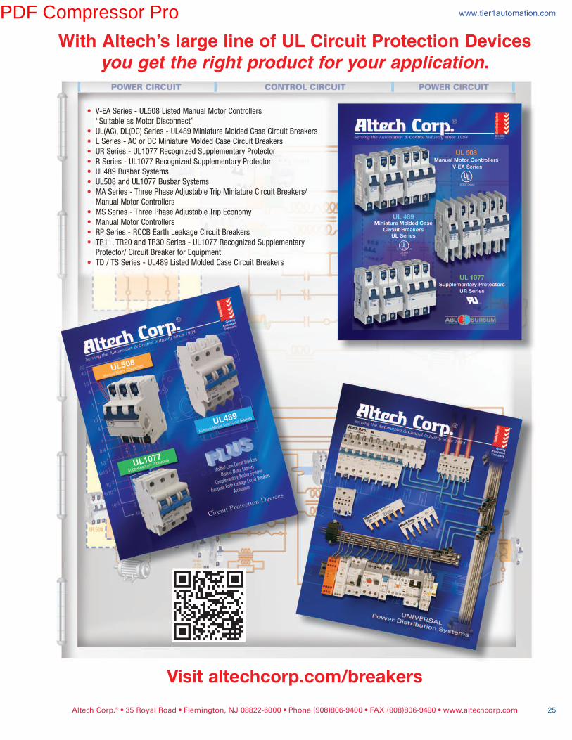
With Altech’s large line of UL Circuit Protection Devices
you get the right product for your application.
Visitaltechcorp.com/breakers
• V-EA Series - UL508 Listed Manual Motor Controllers
“Suitable as Motor Disconnect”
• UL(AC), DL(DC) Series - UL489 Miniature Molded Case Circuit Breakers
• L Series - AC or DC Miniature Molded Case Circuit Breakers
• UR Series - UL1077 Recognized Supplementary Protector
• R Series - UL1077 Recognized Supplementary Protector
• UL489 Busbar Systems
• UL508 and UL1077 Busbar Systems
• MA Series - Three Phase Adjustable Trip Miniature Circuit Breakers/
Manual Motor Controllers
• MS Series - Three Phase Adjustable Trip Economy
• Manual Motor Controllers
• RP Series - RCCB Earth Leakage Circuit Breakers
• TR11, TR20 and TR30 Series - UL1077 Recognized Supplementary
Protector/ Circuit Breaker for Equipment
• TD / TS Series - UL489 Listed Molded Case Circuit Breakers
PDF Compressor Pro www.tier1automation.com

Altech Corp.® • 35 Royal Road • Flemington, NJ 08822-6000 • Phone (908)806-9400 • FAX (908)806-9490 • www.altechcorp.com26
DisconnectCSDL4U DDDL4U
8 mm
43 x 58 mm
9.5 mm
Polyamide 6.6
2 screw clamps
22-10AWG 0.2-4sq.mm 22-10AWG
600 V 1000 V 600 V
14 A 10 A 14 A
7 lb-in 0.5 Nm 7 lb-in
Cat.No. Std.Pk. CSDL4U 100
EPCSFL4U 50
PPCSFL4U 50
CA702 50CA802 50
CA711/2 100CA711/3 100CA711/4 50CA711/10 25
MT8 100MT2 100
8 mm
66 x 88 mm
9.5 mm
Polyamide 6.6
22-10AWG 0.2-4sq.mm 22-10AWG
600 V 800 V 600 V
14 / 35 A 10 A 6.3 / 35 A
7 lb-in 0.5 Nm 7 lb-in
Cat.No. Std.Pk. DDDL4U 20
EPDDFL4U 20
CA702 50CA802 50
CA729/2 100CA729/3 50CA729/4 50CA729/10 10
CA749/2 100CA749/3 50CA749/4 50CA749/10 10
CA703/6 100CA704/6 100CA705/6 100CA737/10 100
CA707/S/Q/3 100
CA711/2 100CA711/3 100CA711/4 50CA711/10 25
MT8 100MT2 100
E220514 E220514
Terminal Width
Height x Length
Stripping Length
Insulation Material
Type of Connection
Approvals
Wire Range
Voltage Rating
Current Rating
Torque
Other Approvals
Terminal Block
End Plate
Isolation Partition
DIN Railfor ordering informationrefer to pages 90-91
End Stopfor ordering informationrefer to page 92
InternalJumper
InsulatedInternalJumper
CurrentBar
Shorting Sleeve & Screw
ExternalJumper
Marking Tags (on terminal)(on lever)
2 pole3 pole4 pole10 pole
Disconnect and test terminals are
an ideal choice for measuring
control and regulatory circuits.
The terminals provide a clear
functional advantage for devices
having utility instruments and
associated transformers.
• CSDL4U - hinged disconnection
and testing terminal,
incorporates a connecting link in
place of the fuse link.
• DDDL4U - double level
disconnect terminal with hinged
disconnect in upper level.
Important: The disconnecting
device is not suitable for interrupt-
ing load. The supply must be
switched off before operating the
slide link/lever.
2 pole3 pole4 pole10 pole
2 pole3 pole4 pole10 pole
2 pole3 pole4 pole10 pole
60947-7-160947-7-1
4screwclamps&1tappedholeforcrossconnection
PDF Compressor Pro www.tier1automation.com
Altech Corp.® • 35 Royal Road • Flemington, NJ 08822-6000 • Phone (908)806-9400 • FAX (908)806-9490 • www.altechcorp.com 27
Terminal Width
Height x Length
Stripping Length
Insulation Material
Type of Connection
Approvals
Wire Range
Voltage Rating
Current Rating
Torque
Other Approvals
*erminal Block
End Plate
DIN Railfor ordering informationrefer to pages 90-91
End Stopfor ordering informationrefer to page 92
ExternalJumper
Marking Tags
2 pole3 pole4 pole10 pole
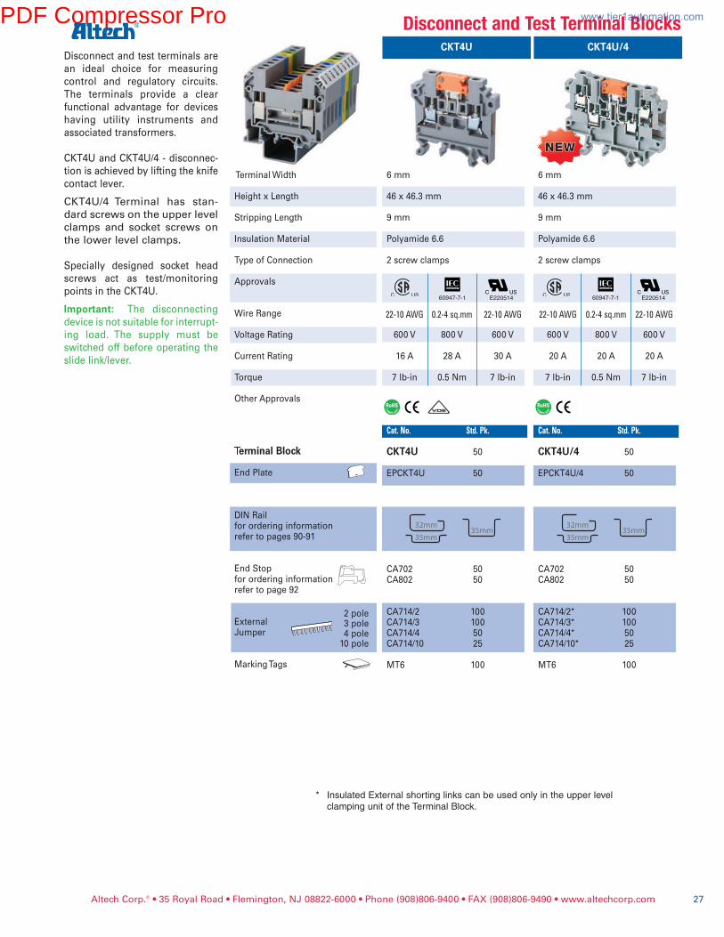
Disconnect and test terminals are
an ideal choice for measuring
control and regulatory circuits.
The terminals provide a clear
functional advantage for devices
having utility instruments and
associated transformers.
CKT4U and CKT4U/4 - disconnec-
tion is achieved by lifting the knife
contact lever.
CKT4U/4 Terminal has stan-
dard screws on the upper level
clamps and socket screws on
the lower level clamps.
Specially designed socket head
screws act as test/monitoring
points in the CKT4U.
Important: The disconnecting
device is not suitable for interrupt-
ing load. The supply must be
switched off before operating the
slide link/lever.
CKT4U
6 mm
46 x 46.3 mm
9 mm
Polyamide 6.6
2 screw clamps
22-10AWG0.2-4sq.mm22-10AWG
600 V 800 V 600 V
16 A 28 A 30 A
7 lb-in 0.5 Nm 7 lb-in
Cat.No. Std.Pk. CKT4U 50
EPCKT4U 50
CA702 50CA802 50
CA714/2 100CA714/3 100CA714/4 50CA714/10 25
MT6 100
E220514
DisconnectandTestTerminalBlocksCKT4U/4
6 mm
46 x 46.3 mm
9 mm
Polyamide 6.6
2 screw clamps
22-10AWG 0.2-4sq.mm 22-10AWG
600 V 800 V 600 V
20 A 20 A 20 A
7 lb-in 0.5 Nm 7 lb-in
Cat.No. Std.Pk. CKT4U/4 50
EPCKT4U/4 50
CA702 50CA802 50
CA714/2* 100CA714/3* 100CA714/4* 50CA714/10* 25
MT6 100
E220514
NEWNEW
* Insulated External shorting links can be used only in the upper level
clamping unit of the Terminal Block.
60947-7-1 60947-7-1
PDF Compressor Pro www.tier1automation.com
Altech Corp.® • 35 Royal Road • Flemington, NJ 08822-6000 • Phone (908)806-9400 • FAX (908)806-9490 • www.altechcorp.com28
Terminal Width
Height x Length
Stripping Length
Insulation Material
Type of Connection
Approvals
Wire Range
Voltage Rating
Current Rating
Torque
Other Approvals
�erminal Block
End Plate
DIN Railfor ordering informationrefer to pages 90-91
End Stopfor ordering informationrefer to page 92
InternalJumper
Slide ShortngLink
Insulated TestSocket
Switchable LinkAssembly
Lock Out Cap
ExternalJumper
Marking Tags
2 pole3 pole4 pole10 pole
2 pole4 pole
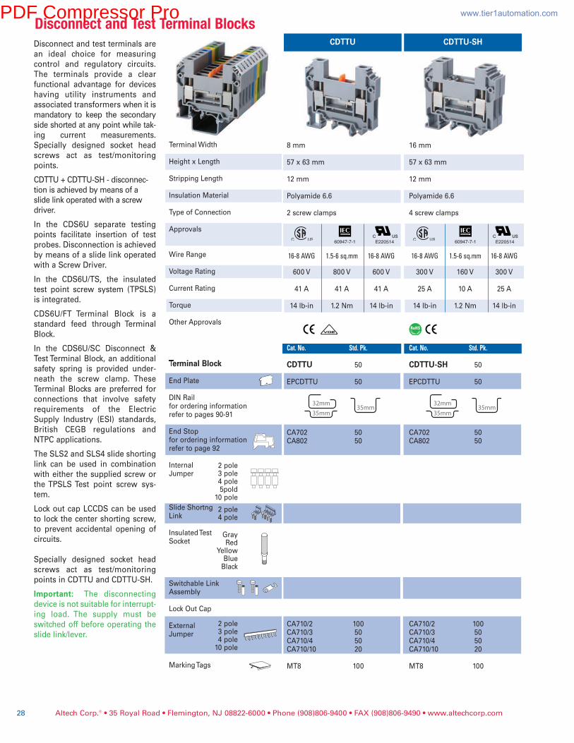
Disconnect and test terminals are
an ideal choice for measuring
control and regulatory circuits.
The terminals provide a clear
functional advantage for devices
having utility instruments and
associated transformers when it is
mandatory to keep the secondary
side shorted at any point while tak-
ing current measurements.
Specially designed socket head
screws act as test/monitoring
points.
CDTTU + CDTTU-SH - disconnec-
tion is achieved by means of a
slide link operated with a screw
driver.
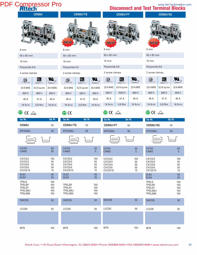
In the CDS6U separate testing
points facilitate insertion of test
probes. Disconnection is achieved
by means of a slide link operated
with a Screw Driver.
In the CDS6U/TS, the insulated
test point screw system (TPSLS)
is integrated.
CDS6U/FT Terminal Block is a
standard feed through Terminal
Block.
In the CDS6U/SC Disconnect &
Test Terminal Block, an additional
safety spring is provided under-
neath the screw clamp. These
Terminal Blocks are preferred for
connections that involve safety
requirements of the Electric
Supply Industry (ESI) standards,
British CEGB regulations and
NTPC applications.
The SLS2 and SLS4 slide shorting
link can be used in combination
with either the supplied screw or
the TPSLS Test point screw sys-
tem.
Lock out cap LCCDS can be used
to lock the center shorting screw,
to prevent accidental opening of
circuits.
Specially designed socket head
screws act as test/monitoring
points in CDTTU and CDTTU-SH.
Important: The disconnecting
device is not suitable for interrupt-
ing load. The supply must be
switched off before operating the
slide link/lever.
DisconnectandTestTerminalBlocks
2 pole3 pole4 pole5pold
10 pole
GrayRed
YellowBlueBlack
CDTTU CDTTU-SH
8 mm
57 x 63 mm
12 mm
Polyamide 6.6
2 screw clamps
16-8AWG 1.5-6sq.mm 16-8AWG
600 V 800 V 600 V
41 A 41 A 41 A
14 lb-in 1.2 Nm 14 lb-in
Cat.No. Std.Pk.
CDTTU 50
EPCDTTU 50
CA702 50CA802 50
CA710/2 100CA710/3 50CA710/4 50CA710/10 20
MT8 100
16 mm
57 x 63 mm
12 mm
Polyamide 6.6
4 screw clamps
16-8AWG 1.5-6sq.mm 16-8AWG
300 V 160 V 300 V
25 A 10 A 25 A
14 lb-in 1.2 Nm 14 lb-in
Cat.No. Std.Pk.
CDTTU-SH 50
EPCDTTU 50
CA702 50CA802 50
CA710/2 100CA710/3 50CA710/4 50CA710/10 20
MT8 100
E220514 E22051460947-7-1 60947-7-1
PDF Compressor Pro www.tier1automation.com
Altech Corp.® • 35 Royal Road • Flemington, NJ 08822-6000 • Phone (908)806-9400 • FAX (908)806-9490 • www.altechcorp.com 29
CDS6U/FT
6 mm
50 x 82 mm
10 mm
Polyamide 6.6
2 screw clamps
22-8AWG 0.2-6sq.mm 22-8AWG
600 V 1000 V 600 V
45 A 41 A 45 A
14 lb-in 0.8 Nm 14 lb-in
Cat.No. Std.Pk. CDS6U/FT 50
EPCDS6U 50
CA702 50CA802 5
CA723/2 100CA723/3 50CA723/4 50CA723/5 50CA723/10 10
SWCDS 50
LCCDS 50
MT8 100
E220514
DisconnectandTestTerminalBlocksCDS6U/SC
6 mm
50 x 82 mm
10 mm
Polyamide 6.6
2 screw clamps
22-8AWG 0.2-6sq.mm 22-8AWG
600 V 800 V 600 V
45 A 41 A 45 A
14 lb-in 0.8 Nm 14 lb-in
Cat.No. Std.Pk. CDS6U/SC 50
EPCDS6U 50
CA702 50CA802 5
CA723/2 100CA723/3 50CA723/4 50CA723/5 50CA723/10 10
SLS2 50SLS4 25
TPSLS 100TPSLSR 100TPSLSY 100TPSLSBU 100TPSLSBK 100
SWCDS 50
LCCDS 50
MT8 100
E220514
NEWNEW NEWNEW
CDS6U CDS6U/TS
8 mm
50 x 82 mm
10 mm
Polyamide 6.6
2 screw clamps
22-8AWG 0.2-6sq.mm 22-8AWG
600 V 800 V 600 V
45 A 41 A 45 A
14 lb-in 0.8 Nm 14 lb-in
Cat.No. Std.Pk.
CDS6U 50
EPCDS6U 50
CA702 50CA802 50
CA723/2 100CA723/3 50CA723/4 50CA723/5 50CA723/10 10
SLS2 50SLS4 25
TPSLS 100TPSLSR 100TPSLSY 100TPSLSBU 100TPSLSBK 100
SWCDS 50
LCCDS 50
MT8 100
8 mm
50 x 82 mm
10 mm
Polyamide 6.6
2 screw clamps
22-8AWG 0.2-6sq.mm 22-8AWG
600 V 630 V 600 V
45 A 41 A 45 A
14 lb-in 0.8 Nm 14 lb-in
Cat.No. Std.Pk.
CDS6U/TS 50
EPCDS6U 50
CA702 50CA802 5
CA723/2 100CA723/3 50CA723/4 50CA723/5 50CA723/10 10
SLS2 50SLS4 25
TPSLSR 100TPSLSY 100TPSLSBU 100TPSLSBK 100
SWCDS 50
LCCDS 50
MT8 100
E220514 E220514
NEWNEW
60947-7-1 60947-7-1 60947-7-1 60947-7-1
PDF Compressor Pro www.tier1automation.com
1 2
1 2
S1 S2
L1
A
1 2
1 2
S1 S2
L1
A
1 2
1 2
S1 S2
L1
A
A
1 2
1 2
S1 S2
L1
A
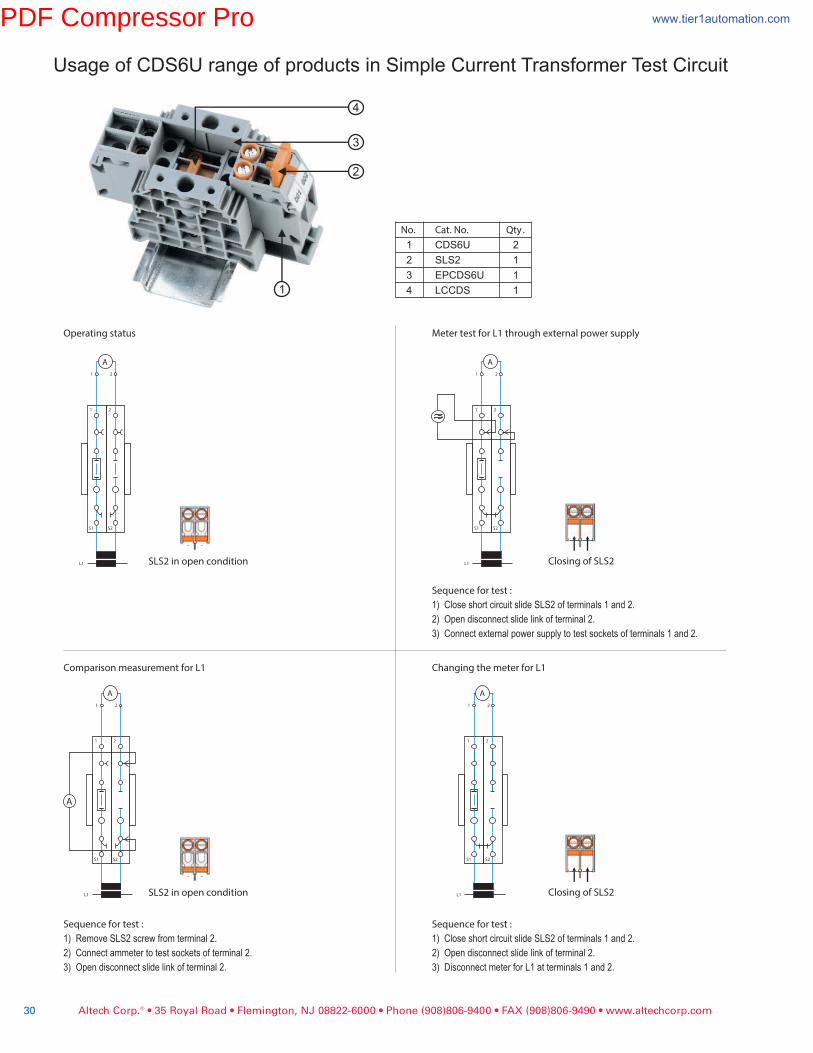
Operating status Meter test for L1 through external power supply
Comparison measurement for L1 Changing the meter for L1
Sequence for test :
1) Close short circuit slide SLS2 of terminals 1 and 2.
2) Open disconnect slide link of terminal 2.
3) Disconnect meter for L1 at terminals 1 and 2.
Sequence for test :
1) Close short circuit slide SLS2 of terminals 1 and 2.
2) Open disconnect slide link of terminal 2.
3) Connect external power supply to test sockets of terminals 1 and 2.
Sequence for test :
1) Remove SLS2 screw from terminal 2.
2) Connect ammeter to test sockets of terminal 2.
3) Open disconnect slide link of terminal 2.
SLS2 in open condition Closing of SLS2
Closing of SLS2SLS2 in open condition
Usage of CDS6U range of products in Simple Current Transformer Test Circuit
No. Cat. No. Qty .
1 CDS6U 2
2 SLS2 1
3 EPCDS6U 1
4 LCCDS 11
2
3
4
Altech Corp.® • 35 Royal Road • Flemington, NJ 08822-6000 • Phone (908)806-9400 • FAX (908)806-9490 • www.altechcorp.com30
PDF Compressor Pro www.tier1automation.com
1 2 3 4 5 6
S1 S2 S1 S2 S1 S2
A A A
A
1 2 3 4 5 6
S1 S2 S1 S2 S1 S2
A A A
1 2 3 4 5 6
S1 S2 S1 S2 S1 S2
A A A
1 2 3 4 5 6
S1 S2 S1 S2 S1 S2
A A A
1 2 3 4 5 6
S1 S2 S1 S2 S1 S2
A A A
A
1 2 3 4 5 6
S1 S2 S1 S2 S1 S2
A A A
1 2 3 4 5 6
S1 S2 S1 S2 S1 S2
A A A
1 2 3 4 5 6
S1 S2 S1 S2 S1 S2
A A A
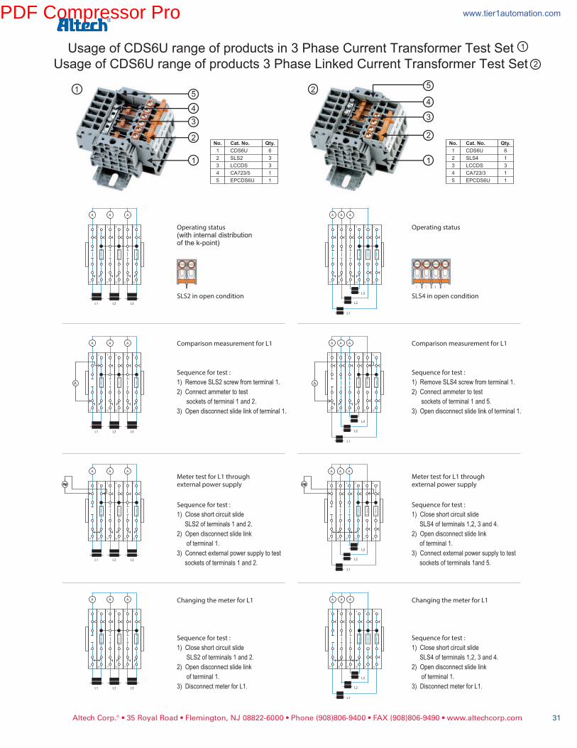
Operating status(with internal distributionof the k-point)
Comparison measurement for L1
Sequence for test :
1) Remove SLS2 screw from terminal 1.
2) Connect ammeter to test
sockets of terminal 1 and 2.
3) Open disconnect slide link of terminal 1.
Meter test for L1 throughexternal power supply
Sequence for test :
1) Close short circuit slide
SLS2 of terminals 1 and 2.
2) Open disconnect slide link
of terminal 1.
3) Connect external power supply to test
sockets of terminals 1 and 2.
Changing the meter for L1
Sequence for test :
1) Close short circuit slide
SLS2 of terminals 1 and 2.
2) Open disconnect slide link
of terminal 1.
3) Disconnect meter for L1.
Operating status
Comparison measurement for L1
Sequence for test :
1) Remove SLS4 screw from terminal 1.
2) Connect ammeter to test
sockets of terminal 1 and 5.
3) Open disconnect slide link of terminal 1.
Meter test for L1 throughexternal power supply
Sequence for test :
1) Close short circuit slide
SLS4 of terminals 1,2, 3 and 4.
2) Open disconnect slide link
of terminal 1.
3) Connect external power supply to test
sockets of terminals 1and 5.
Changing the meter for L1
Sequence for test :
1)
SLS4 of terminals 1,2, 3 and 4.
2) Open disconnect slide link
of terminal 1.
3) Disconnect meter for L1.
Close short circuit slide
SLS2 in open condition SLS4 in open conditionL1 L2 L3
L1 L2 L3
L1 L2 L3
L1 L2 L3
L1
L2
L3
L1
L2
L3
L1
L2
L3
L1
L2
L3
3
2
1
4
5
3
2
1
4
5
Usage of CDS6U range of products in 3 Phase Current Transformer Test Set
Usage of CDS6U range of products 3 Phase Linked Current Transformer Test Set
1
2
1 2
Altech Corp.® • 35 Royal Road • Flemington, NJ 08822-6000 • Phone (908)806-9400 • FAX (908)806-9490 • www.altechcorp.com 31
PDF Compressor Pro www.tier1automation.com
Altech Corp.® • 35 Royal Road • Flemington, NJ 08822-6000 • Phone (908)806-9400 • FAX (908)806-9490 • www.altechcorp.com32
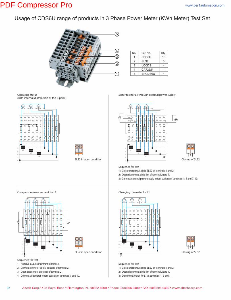
Usage of CDS6U range of products in 3 Phase Power Meter (KWh Meter) Test Set
Operating status(with internal distribution of the k-point)
Meter test for L1 through external power supply
Sequence for test :
1) Close short circuit slide SLS2 of terminals 1 and 2.
2) Open disconnect slide link of terminal 2 and 7.
3) Connect external power supply to test sockets of terminals 1, 2 and 7, 10.
Comparison measurement for L1
Sequence for test :
1) Remove SLS2 screw from terminal 2.
2) Connect ammeter to test sockets of terminal 2.
3) Open disconnect slide link of terminal 2.
4) Connect voltameter to test sockets of terminals 7 and 10.
Changing the meter for L1
Sequence for test :
1) Close short circuit slide SLS2 of terminals 1 and 2.
2) Open disconnect slide link of terminal 2 and 7.
3) Disconnect meter for L1 at terminals 1, 2 and 7.
SLS2 in open condition Closing of SLS2
Closing of SLS2
No. Cat. No. Qty .
1 CDS6U 10
2 SLS2 3
3 LCCDS 4
4 CA723/5 1
5 EPCDS6U 1
1 7 2 3 8 4 5 9 6 10
1 2 3 4 5 6 7 8 9 10
S1 S2 S1 S2 S1 S2 L1 L2 L3 N
L1
L2
L3
N
PE
KW/hKW/hKW/h
L1
L2
L3
VA
1 7 2 3 8 4 5 9 6 10
1 2 3 4 5 6 7 8 9 10
S1 S2 S1 S2 S1 S2 L1 L2 L3 N
L1
L2
L3
N
PE
KW/hKW/hKW/h
L1
L2
L3
1 7 2 3 8 4 5 9 6 10
1 2 3 4 5 6 7 8 9 10
S1 S2 S1 S2 S1 S2 L1 L2 L3 N
L1
L2
L3
N
PE
KW/hKW/hKW/h
L1
L2
L3
1 7 2 3 8 4 5 9 6 10
1 2 3 4 5 6 7 8 9 10
S1 S2 S1 S2 S1 S2 L1 L2 L3 N
L1
L2
L3
N
PE
KW/hKW/hKW/h
L1
L2
L3
SLS2 in open condition
3
2
1
4
5
PDF Compressor Pro www.tier1automation.com

Altech Corp.® • 35 Royal Road • Flemington, NJ 08822-6000 • Phone (908)806-9400 • FAX (908)806-9490 • www.altechcorp.com 33
Altech’spopularindustrialenclosureskeepyoucoveredwiththeirhighqualityandattractivedesign.
AllatVeryCompetitivePrices...andmanyavailableforimmediatedelivery!
Customizationavailable!
• Polycarbonate/Polystyrene enclosures will last indefinitely without corrosion
• Non-metallic enclosures withstand bumps and blows, they will not dent
• Surface finish does not deteriorate and requires no special painting or refinishing
• Resist weak and strong acids and alkali
• Non-metallic enclosures weigh significantly less than metal, simplifying handling
• Enclosures can be easily customized
• 16 different enclosures with up to 3
different cover heights
• Polystyrene or Polycarbonate
• IP66 (NEMA 4X)
• 50 x 52 x 35 to 360 x 254 x 165 mm
• 16 sizes available
• ABS or Polycarbonate
• IP67 (NEMA TYPE 4X)
• Recesed Cover
• 84 x 82 x 55 to 302 x 232 x 110 mm
• IP65 protection, which is necessary
for industry approval.
• Aluminum
• High degree of resistance to chem-
cals and other damaging materials.
• 50 x 45 x 30 to 330 x 230 x 110 mm
• Two to four high grade self taping
screws secure the lid non-flammable
• non-flammable Polystyrene
• Tongue and groove sealing system
with polyurethane gasket
• 80 x 80 x 52 to 250 x 250 x 115 mm
• 6 different sizes
• For harsh environments
• Glass reinforced Polycarbonate
• Impervious to sea air and water
• 80 x 80 x 52 to 250 x 250 x 115 mm
• Low and high covers in gray or
tinted transparent
• Enclosures are combinable
• IP65 protection
• 150 x 300 x 132 to 600 x 300 x 210 mm
• UL listed
• IP65 protection
• Dust and moisture proof
• Polycarbonate
• 130 x 94 x 80 to 361 x 254 x 110 mm
• IEC protection
• Up to IP65 protection
• Dust and moisture proof
• Polystyrene or Polycarbonate
• 100 x 150 x 96 to 900 x 300 x 142 mm
• Junction boxes
• IP55 protection
• Dust and moisture proof
• Semi rigid polypropylene
• 75 x 75 x 42 to 199 x 149 x 70 mm
• Universal fit for nearly all
22.5mm diameter push buttons
• UV, weather and impact resistant
• IP66 (NEMA 4X) capabile
• 94 x 94 x 81 to 180 x 94 x 81 mm
• Liquid Tight Strain Relief connectors
and connector assemblies
• Mounting plates
• DIN rail support racks
• Key locksets, Hinge kits and more
PDF Compressor Pro www.tier1automation.com

CDB4/x* CDB4/x(1)**Altech CDB Compact Distribu-
tion Blocks are an ideal choice
for a simplified distribution sys-
tem. A lug/bolt secures the
incoming cable and the screw
clamp design of the block pro-
vides the outgoing connec-
tions. These provide easy con-
nect points and ensure perfect
continuity for distribution. A
protective shield effectively
shrouds the incoming connec-
tion.
ApplicationInformation:Sum of outgoing currents on
either side of center should not
exceed half the maximum per-
missible incoming current.
Sum of total outgoing currents
should not exceed maximum
permissible incoming current.
Connection for higher outgoing
currents should be done
through the terminal nearest to
the incoming connection.
Terminal Width
Height & Width
Stripping Length
Insulation Material
Type of Connection
Approvals
Wire Range
Voltage Rating
Current Rating
Torque
Other Approvals
Terminal Block
DIN Railfor ordering informationrefer to pages 90-91
End Stopfor ordering informationrefer to page 92
Marking Tags
Warning Label
6 mm
45 x 43 mm
8 mm
Polyamide 6.6
10-8AWG 6-16sq.mm 10-8AWG22-12AWG 0.2-4sq.mm 22-10AWG
600 V 800 V 600 V
50 A 64 A 50 A25 A 32 A 35 A
26 lb-in 2.0 Nm 26 lb-in7 lb-in 0.5 Nm 7 lb-in
Cat.No. HxWxL(mm) Outputs Std.Pk.
CDB4/1 45 x 43 x 44 4 10CDB4/2 45 x 43 x 56 8 10CDB4/3 45 x 43 x 68 12 10CDB4/4 45 x 43 x 80 16 10CDB4/5 45 x 43 x 96 20 10CDB4/6 45 x 43 x 108 24 10
Cat.No. Std.Pk.
CA702 50CA802 50
MT6 100
* NOTE:x signifies how many blocks are oneach side of input.
InputOutput
InputMax. Individual Output
InputOutput
1Lug/M5boltconnectionforringlugScrewclampconnection
InputOutput
6 mm
45 x 43 mm
8 mm
Polyamide 6.6
10-8AWG 6-16sq.mm 10-8AWG22-12AWG 0.5-4sq.mm 22-10AWG
600 V 800 V 600 V
50 A 64 A 50 A25 A 64 A 35 A
26 lb-in 2.0 Nm 26 lb-in7 lb-in 0.5 Nm 7 lb-in
Cat.No. HxWxL(mm) Outputs Std.Pk
CDB4/2(1) 45 x 43 x 52 6 10CDB4/3(1) 45 x 43 x 58 8 10CDB4/4(1) 45 x 43 x 64 10 10CDB4/5(1) 45 x 43 x 70 12 10CDB4/6(1) 45 x 43 x 76 14 10CDB4/10(1)45 x 43 x 100 22 10CDB4/11(1)45 x 43 x 106 24 10
Cat.No. Std.Pk.
CA702 50CA802 50
MT6 100
** NOTE:x signifies number of blocks on leftside of input. 1 block is on right side.
1LugM5/boltconnectionforringlugScrewclampconnection
E220514 E220514
Altech Corp.® • 35 Royal Road • Flemington, NJ 08822-6000 • Phone (908)806-9400 • FAX (908)806-9490 • www.altechcorp.com34
DistributionBlock
COLOR BLOCKS(otherthanstandardgrey)
When ordering please addcolor suffix to Cat. No.
ExampleforcolorRed:Cat.No./R
Color OrderingSuffixRed R
Yellow Y
Blue BU
Green G
ConsultAltechforavailability:Orange O
Beige BG
Dark Brown DB
Black BL
White W
60947-7-1 60947-7-1
PDF Compressor Pro www.tier1automation.com
Altech Corp.® • 35 Royal Road • Flemington, NJ 08822-6000 • Phone (908)806-9400 • FAX (908)806-9490 • www.altechcorp.com 35
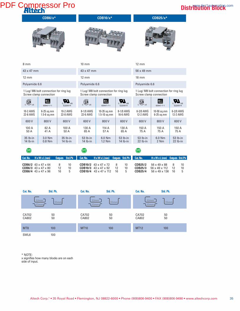
CDB25/x*
12 mm
56 x 49 mm
18 mm
Polyamide 6.6
6-2/0AWG 10-50sq.mm 6-2/0AWG12-2AWG 6-25sq.mm 12-2AWG
600 V 800 V 600 V
150 A 150 A 150 A75 A 75 A 75 A
53 lb-in 6.0 Nm 53 lb-in22 lb-in 2 Nm 22 lb-in
Cat.No. HxWxL(mm) Outputs Std.Pk
CDB25/2 56 x 49 x 88 8 10CDB25/3 56 x 49 x 112 12 10CDB25/4 56 x 49 x 136 16 5
Cat.No. Std.Pk.
CA702 50CA802 50
MT12 100
CDB6/x* CDB10/x*
8 mm
43 x 47 mm
12 mm
Polyamide 6.6
10-2AWG 6-25sq.mm 10-2AWG22-8AWG 1.5-6sq.mm 22-8AWG
600 V 800 V 600 V
100 A 82 A 100 A50 A 41 A 50 A
35 lb-in 3.0 Nm 35 lb-in14 lb-in 0.8 Nm 14 lb-in
Cat.No. HxWxL(mm) Outputs Std.Pk
CDB6/2 43 x 47 x 64 8 10CDB6/3 43 x 47 x 80 12 10CDB6/4 43 x 47 x 96 16 5
Cat.No. Std.Pk.
CA702 50CA802 50
MT8 100
SWL6 100
* NOTE:x signifies how many blocks are on eachside of input.
1Lug/M6boltconnectionforringlugScrewclampconnection
10 mm
43 x 47 mm
12 mm
Polyamide 6.6
8-1/0AWG 10-35sq.mm 8-1/0AWG22-6AWG 1.5-10sq.mm 16-6AWG
600 V 800 V 600 V
130 A 114 A 130 A65 A 57 A 65 A
53 lb-in 6.0 Nm 53 lb-in14 lb-in 1.2 Nm 14 lb-in
Cat.No. HxWxL(mm) Outputs Std.Pk
CDB10/2 43 x 47 x 72 8 10CDB10/3 43 x 47 x 92 12 10CDB10/4 43 x 47 x 112 16 5
Cat.No. Std.Pk.
CA702 50CA802 50
MT10 100
1Lug/M8boltconnectionforringlugScrewclampconnection
1Lug/M8boltconnectionforringlugScrewclampconnection
E220514 E220514 E220514
DistributionBlock
60947-7-1 60947-7-1 60947-7-1
PDF Compressor Pro www.tier1automation.com
Terminal Width
Height & Width
Stripping Length
Insulation Material
Type of Connection
Approvals
Wire Range
Voltage Rating
Current Rating
Torque
Other Approvals
�erminal Block
DIN Railfor ordering informationrefer to pages 90-91
End Stopfor ordering informationrefer to page 92
Marking Tags
Warning Label
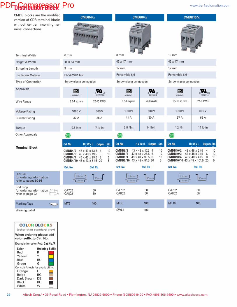
6 mm
45 x 43 mm
9 mm
Polyamide 6.6
0.2-4sq.mm 22-10AWG
1000 V 600 V
32 A 35 A
0.5 Nm 7 lb-in
Cat.No. HxWxL Outputs Std.(mm) Pk.
CMDB4/2 45 x 43 x 13.5 4 10CMDB4/3 45 x 43 x 19.5 6 10CMDB4/4 45 x 43 x 25.5 8 5CMDB4/10 45 x 43 x 61.5 20 5
Cat.No. Std.Pk.
CA702 50CA802 50
MT6 100
Screwclampconnection
10 mm
43 x 47 mm
12 mm
Polyamide 6.6
1.5-10sq.mm 22-6AWG
1000 V 600 V
57 A 65 A
1.2 Nm 14 lb-in
Cat.No. HxWxL Outputs Std.(mm) Pk.
CMDB10/2 43 x 48 x 21.5 4 10CMDB10/3 43 x 48 x 31.5 6 10CMDB10/4 43 x 48 x 41.5 8 10CMDB10/10 43 x 48 x 101.5 20 5
Cat.No. Std.Pk.
CA702 50CA802 50
MT10 100
Screwclampconnection
8 mm
43 x 47 mm
12 mm
Polyamide 6.6
1.5-6sq.mm 22-8AWG
1000 V 600 V
41 A 50 A
0.8 Nm 14 lb-in
Cat.No. HxWxL Outputs Std.(mm) Pk.
CMDB6/2 43 x 48 x 17.5 4 10CMDB6/3 43 x 48 x 25.5 6 10CMDB6/4 43 x 48 x 33.5 8 10CMDB6/10 43 x 48 x 81.5 20 5
Cat.No. Std.Pk.
CA702 50CA802 50
MT8 100
SWL6 100
Screwclampconnection
E220514 E220514 E220514
Altech Corp.® • 35 Royal Road • Flemington, NJ 08822-6000 • Phone (908)806-9400 • FAX (908)806-9490 • www.altechcorp.com36
CMDB4/x CMDB10/xCMDB6/xCMDB blocks are the modified
version of CDB terminal blocks
without central incoming ter-
minal connections.
DistributionBlock
COLOR BLOCKS(otherthanstandardgrey)
When ordering please addcolor suffix to Cat. No.
ExampleforcolorRed:Cat.No./R
Color OrderingSuffixRed R
Yellow Y
Blue BU
Green G
ConsultAltechforavailability:Orange O
Beige BG
Dark Brown DB
Black BL
White W
60947-7-1 60947-7-1 60947-7-1
PDF Compressor Pro www.tier1automation.com
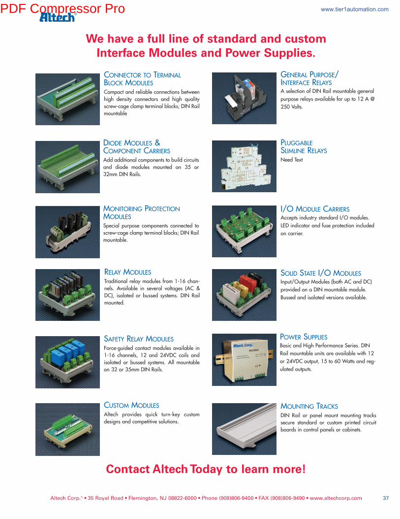
Altech Corp.® • 35 Royal Road • Flemington, NJ 08822-6000 • Phone (908)806-9400 • FAX (908)806-9490 • www.altechcorp.com 37
CONNECTOR TO TERMINALBLOCK MODULESCompactandreliableconnectionsbetweenhigh density connectors and high qualityscrew-cageclampterminalblocks;DINRailmountable
PLUGGABLESLIMLINE RELAYSNeedText
DIODE MODULES &COMPONENT CARRIERSAddadditionalcomponentstobuildcircuitsand diode modules mounted on 35 or32mmDINRails.
MONITORING PROTECTIONMODULESSpecial purpose components connected toscrew-cageclampterminalblocks;DINRailmountable.
POWER SUPPLIESBasicandHighPerformanceSeries.DINRailmountableunitsareavailablewith12or24VDCoutput,15to60Wattsandreg-ulatedoutputs.
SOLID STATE I/OMODULESInput/OutputModules(bothACandDC)providedonaDINmountablemodule.Bussedandisolatedversionsavailable.
RELAY MODULESTraditionalrelaymodulesfrom1-16chan-nels. Available in several voltages (AC &DC), isolated or bussed systems. DIN Railmounted.
SAFETY RELAY MODULESForce-guidedcontactmodulesavailable in1-16 channels, 12 and 24VDC coils andisolated or bussed systems. All mountableon32or35mmDINRails.
CUSTOM MODULESAltech provides quick turn-key customdesignsandcompetitivesolutions.
GENERAL PURPOSE/INTERFACE RELAYSAselectionofDINRailmountablegeneralpurposerelaysavailableforupto12A@250Volts.
MOUNTING TRACKSDIN Rail or panel mount mounting trackssecure standard or custom printed circuitboardsincontrolpanelsorcabinets.
I/OMODULE CARRIERSAcceptsindustrystandardI/Omodules.LEDindicatorandfuseprotectionincludedoncarrier.
We have a full line of standard and customInterface Modules and Power Supplies.
Contact Altech Today to learn more!
PDF Compressor Pro www.tier1automation.com
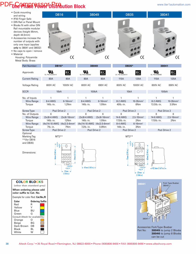
Part Number:
Approvals
Current Rating
Voltage Rating
SCCR
No. of Inputs
Wire Range
Torque
Screw Type
No. of Outputs
Wire Range
Torque
Wire Range
Torque
Screw Type
Optional
Marking Tag
**(for DB16
and DB35)
Dimensions:
DB16*
80A 80A
600V AC 1000V AC
10kA
1 1
8-4 AWG 6-16mm2
14lb.-in. 1.2Nm
Pozi Drive 2
6 6
(2x)8-4 AWG (2x)6-16mm2
14lb.-in. 12Nm
(4x)14-10 AWG (4x)2.5-6mm2
7lb.-in. 7Nm
Pozi Drive 2
MT2**
38049
80A 80A
600V AC 690V AC
100kA
1 1
8-4 AWG 6-16mm2
14lb.-in. 1.5Nm
Pozi Drive 2
6 6
(2x)8-4 AWG (2x)6-16mm2
14lb.-in. 1.5Nm
(4x)14-10 AWG (4x)2.5-6mm2
7.2lb.-in. 0.8Nm
Pozi Drive 2
DB35*
115A 125A
600V AC 1000V AC
10kA
1 1
8-2 AWG 10-35mm2
40lb.-in. 6Nm
Pozi Drive 2
6 6
14-6 AWG 2.5-10mm2
17.5lb.-in. 2Nm
8-4 AWG 6-16mm2
14lb.-in. 3Nm
Pozi Drive 2
MT2**
38041
115A 125A
600V AC 690V AC
100kA
1 1
8-2 AWG 10-35mm2
13.5lb.-in. 3.5Nm
Pozi Drive 2
6 6
14-6 AWG 2.5-16mm2
17.5lb.-in. 2Nm
Pozi Drive 2
Altech Corp.® • 35 Royal Road • Flemington, NJ 08822-6000 • Phone (908)806-9400 • FAX (908)806-9490 • www.altechcorp.com38
DB16• Quick mounting
and wiring
• IP20 Finger Safe
• DIN Rail or Panel Mount
• Blocks fit with other DIN
Rail mountable modular
devices (height 95mm,
depth 44.5mm)
• Accessories increase the
number of outputs with
only one input (applies
>nly to 38041 and 38032)
• No caps to open / remove
• Material
Housing: Polyamide
Metal Body: Brass
Fork Type Busbar
38045
38041
UL File E220514 UL File E98082 UL File E220514 UL File E98082
Accessories: Fork Type Busbar
Part No: 38045 to jump 2 Blocks
38046 to jump 8 Blocks
can be cut
38041
38049 DB35 38041
OnePhasePowerDistributionBlock
COLOR BLOCKS(otherthanstandardgrey)
When ordering please addcolor suffix to Cat. No.
ExampleforcolorRed:Cat.No./R
Color OrderingSuffixRed R
Yellow Y
Blue BU
Green G
ConsultAltechforavailability:Orange O
Beige BG
Dark Brown DB
Black BL
White W
PDF Compressor Pro www.tier1automation.com
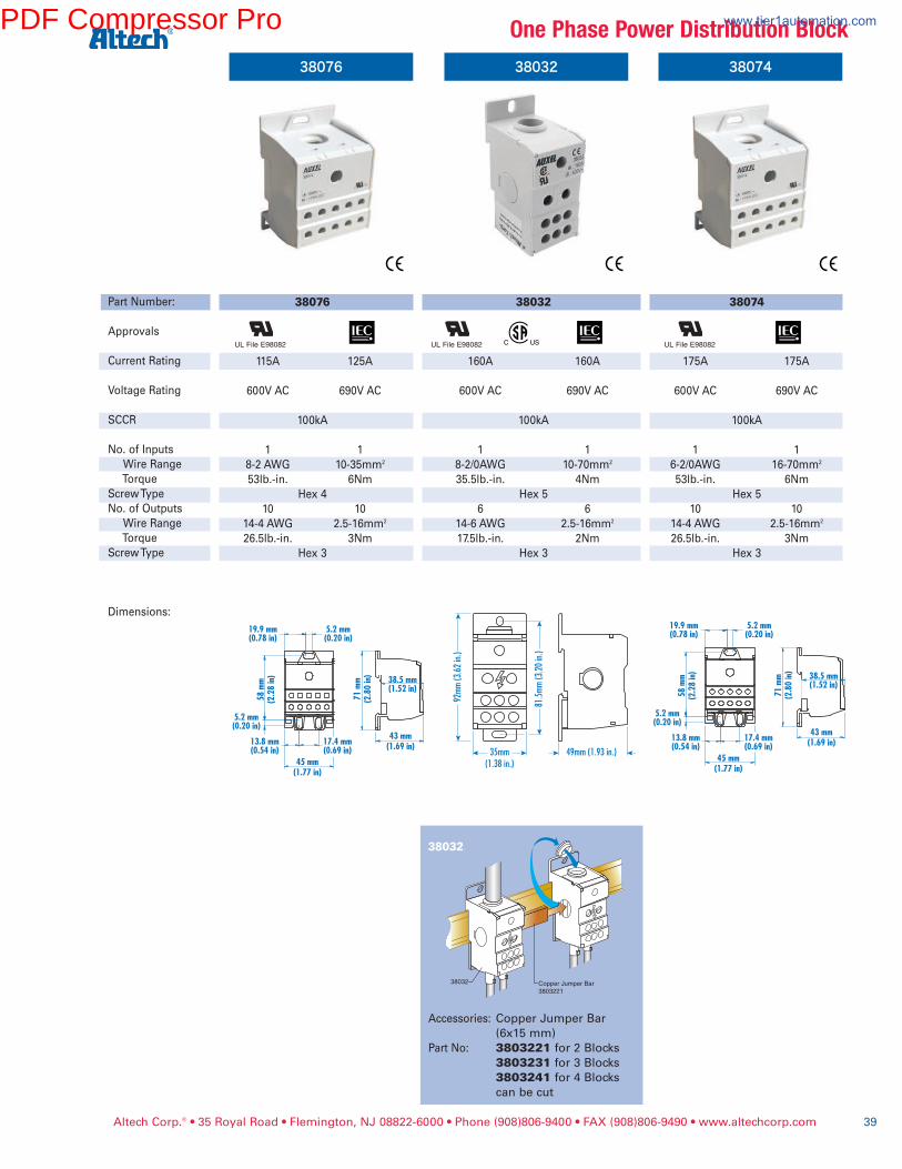
Altech Corp.® • 35 Royal Road • Flemington, NJ 08822-6000 • Phone (908)806-9400 • FAX (908)806-9490 • www.altechcorp.com 39
43 mm
(1.69 in)
38.5 mm(1.52 in)
45 mm
(1.77 in)
58
mm
(2.2
8 in)
5.2 mm(0.20 in)
17.4 mm(0.69 in)
13.8 mm(0.54 in)
19.9 mm(0.78 in)
5.2 mm(0.20 in)
71
mm
(2.8
0 in)
43 mm
(1.69 in)
38.5 mm(1.52 in)
45 mm
(1.77 in)
58
mm
(2.2
8 in)
5.2 mm(0.20 in)
17.4 mm(0.69 in)
13.8 mm(0.54 in)
19.9 mm(0.78 in)
5.2 mm(0.20 in)
71
mm
(2.8
0 in)
38032
38032
160A 160A
600V AC 690V AC
100kA
1 1
8-2/0AWG 10-70mm2
35.5lb.-in. 4Nm
Hex 5
6 6
14-6 AWG 2.5-16mm2
17.5lb.-in. 2Nm
Hex 3
38076
Part Number:
Approvals
Current Rating
Voltage Rating
SCCR
No. of Inputs
Wire Range
Torque
Screw Type
No. of Outputs
Wire Range
Torque
Screw Type
Dimensions:
38076
115A 125A
600V AC 690V AC
100kA
1 1
8-2 AWG 10-35mm2
53lb.-in. 6Nm
Hex 4
10 10
14-4 AWG 2.5-16mm2
26.5lb.-in. 3Nm
Hex 3
38074
38074
175A 175A
600V AC 690V AC
100kA
1 1
6-2/0AWG 16-70mm2
53lb.-in. 6Nm
Hex 5
10 10
14-4 AWG 2.5-16mm2
26.5lb.-in. 3Nm
Hex 3
Copper Jumper Bar
3803221
38032
UL File E98082 UL File E98082 UL File E98082
Accessories: Copper Jumper Bar
(6x15 mm)
Part No: 3803221 for 2 Blocks
3803231 for 3 Blocks
3803241 for 4 Blocks
can be cut
38032
OnePhasePowerDistributionBlockPDF Compressor Pro www.tier1automation.com

Altech Corp.® • 35 Royal Road • Flemington, NJ 08822-6000 • Phone (908)806-9400 • FAX (908)806-9490 • www.altechcorp.com40
38020 38019
Part Number:
Approvals
Current Rating
Voltage Rating
SCCR
No. of Inputs
Wire Range
Torque
Screw Type
No. of Outputs
Wire Range
Torque
Wire Range
Torque
Wire Range
Torque
Screw Type
Dimensions:
38020 38019
230A 250A 310A 400A
600V AC 690V AC 600V AC 690V AC
100kA 100kA
1 1 1 1
2-4/0AWG 35-120mm2 3/0-350mcm 95-185mm2
170lb.-in. 19Nm 230lb.-in. 25Nm
Hex 6 Hex 8
11 11 11 11
(2x) 14-2AWG (2x) 2.5-35mm2 (2x) 14-2AWG (2x) 2.5-35mm2
31lb.-in. 3.5Nm 31lb.-in. 3.5Nm
(5x) 14-6AWG (5x) 2.5-16mm2 (5x) 14-6AWG (5x) 2.5-16mm2
17.5lb.-in. 2Nm 17.5lb.-in. 2Nm
(4x) 14-8AWG (4x) 2.5-10mm2 (4x) 14-8AWG (4x) 2.5-10mm2
17.5lb.-in. 2Nm 17.5lb.-in. 2Nm
standard screwdriver standard screwdriver
UL File E98082 UL File E98082
• Quick mounting and wiring
• IP20 Finger Safe
• DIN Rail or Panel Mount
• Blocks fit with other DIN Rail
mountable modular devices
(height 95mm, depth 44.5mm)
• Accessories increase the
number of outputs with only
one input.
• No caps to open or remove
• Material
Housing: Polyamide
Metal Body: Brass
OnePhasePowerDistributionBlockPDF Compressor Pro www.tier1automation.com

Altech Corp.® • 35 Royal Road • Flemington, NJ 08822-6000 • Phone (908)806-9400 • FAX (908)806-9490 • www.altechcorp.com 41
38075 38073
Part Number:
Approvals
Current Rating
Voltage Rating
SCCR
No. of Inputs
Wire Range
Torque
Screw Type
No. of Outputs
Wire Range
Torque
Screw Type
Dimensions:
38075 38073
115A 115A 175A 175A
600V AC 690V AC 600V AC 690V AC
100kA 100kA
3x1 3x1 3x1 3x1
8-2AWG 10-35mm2 8-2/0AWG 10-70mm2
31lb.-in. 3.5Nm 35.5lb.-in. 4Nm
Hex 4 Hex 5
3x6 3x6 3x6 3x6
14-4AWG 2.5-16mm2 14-4AWG 2.5-16mm2
17.5lb.-in. 2Nm 17.5 lb.-in. 2Nm
Hex 3 Hex 3
3Pole 3Pole
• Quick mounting and wiring
• IP20 Finger Safe
• DIN Rail or Panel Mount
• Blocks fit with other DIN Rail
mountable modular devices
• Same compact size for
both ratings
• No caps to open or remove
• Material
Housing: Polyamide
Metal Body: Brass
UL File E98082 UL File E98082
ThreePhasePowerDistributionBlockPDF Compressor Pro www.tier1automation.com
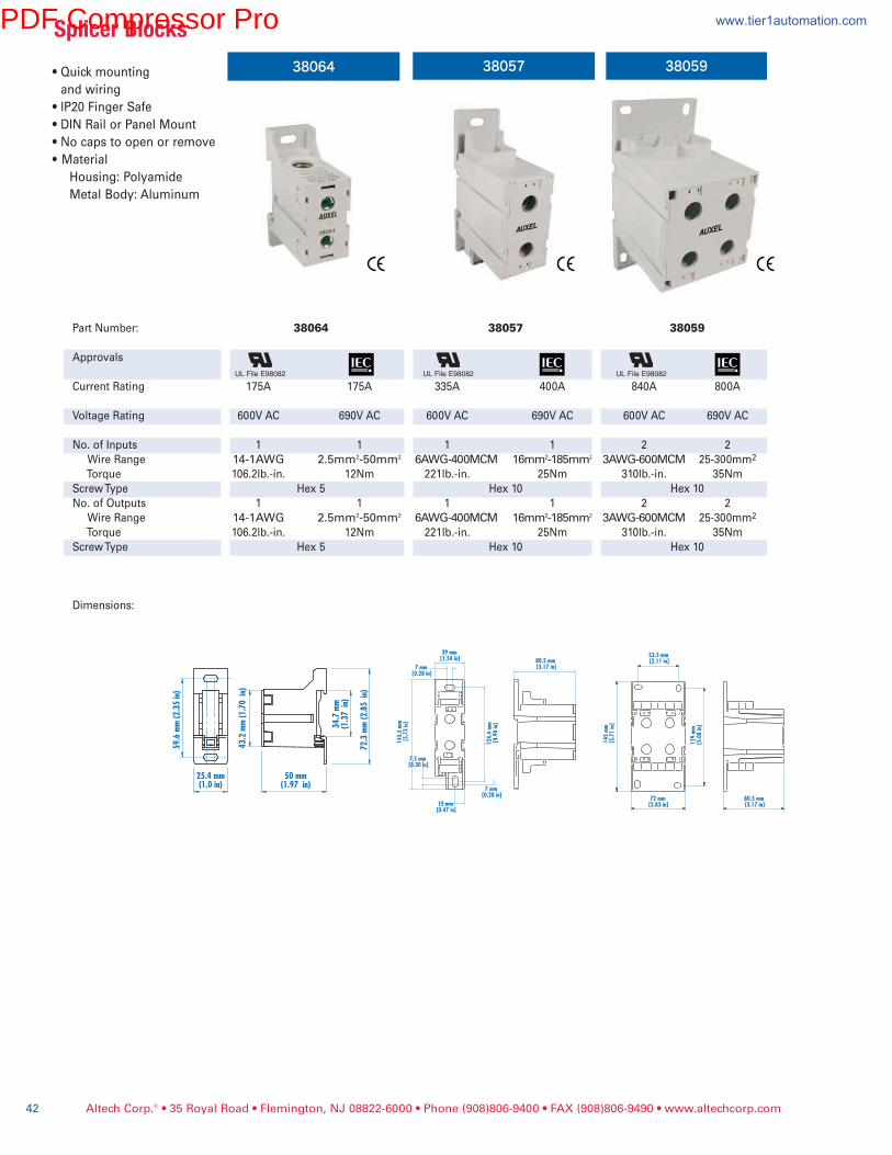
Altech Corp.® • 35 Royal Road • Flemington, NJ 08822-6000 • Phone (908)806-9400 • FAX (908)806-9490 • www.altechcorp.com42
• Quick mounting
and wiring
• IP20 Finger Safe
• DIN Rail or Panel Mount
• No caps to open or remove
• Material
Housing: Polyamide
Metal Body: Aluminum
38064 38057
Part Number:
Approvals
Current Rating
Voltage Rating
No. of Inputs
Wire Range
Torque
Screw Type
No. of Outputs
Wire Range
Torque
Screw Type
Dimensions:
38064
175A 175A
600V AC 690V AC
1 1
14-1AWG 2.5mm2-50mm2
106.2lb.-in. 12Nm
Hex 5
1 1
14-1AWG 2.5mm2-50mm2
106.2lb.-in. 12Nm
Hex 5
38057
335A 400A
600V AC 690V AC
1 1
6AWG-400MCM 16mm2-185mm2
221lb.-in. 25Nm
Hex 10
1 1
6AWG-400MCM 16mm2-185mm2
221lb.-in. 25Nm
Hex 10
38059
840A 800A
600V AC 690V AC
2 2
3AWG-600MCM 25-300mm2
310lb.-in. 35Nm
Hex 10
2 2
3AWG-600MCM 25-300mm2
310lb.-in. 35Nm
Hex 10
59
.6 m
m (
2.3
5 in)
25.4 mm(1.0 in)
50 mm(1.97 in)
72
.3 m
m (
2.8
5
in)
34
.7 m
m(1
.37
in
)
43
.2 m
m (
1.7
0
in)
39 mm [1.54 in]
7 mm [0.28 in]
14
5.5
mm
[5
.73
in]
7.5 mm [0.30 in]
12
4.4
mm
[4
.90
in]
12 mm [0.47 in]
7 mm [0.28 in]
80.5 mm [3.17 in]
53.5 mm [2.11 in]
14
5 m
m [
5.7
1 in]
12
9 m
m [
5.0
8 in]
72 mm [2.83 in]
80.5 mm [3.17 in]
38059
UL File E98082 UL File E98082 UL File E98082
SplicerBlocksPDF Compressor Pro www.tier1automation.com

Altech Corp.® • 35 Royal Road • Flemington, NJ 08822-6000 • Phone (908)806-9400 • FAX (908)806-9490 • www.altechcorp.com 43
CTT2.5UK/J/T/E
Terminal Width
Height x Length
Stripping Length
Insulation Material
Current Carrying Material
Type of Connection
Wire Range
Voltage Rating
Current Rating
Torque
Terminal Block
End Plate
Isolation Plate
DIN Railfororderinginformationrefertopage63
End Clamp
Marking Tags(MT Type)
10 mm
45 x 43 mm
8 mm
Polyamide 6.6
*
4 screw clamps
24-12 AWG
300 V
10 A
7 lb-in
Cat.No. Std.Pk.
CTT2.5UK 50CTT2.5UJ 50CTT2.5UT 50CTT2.5UE 50
EP2.5/4UN 50
PP2.5/4UN 50
CA802 100CA702 100
included
Altech thermocouple terminal
blocks are designed for use in
temperature measuring circuits.
The current carrying part of the
terminal blocks have the same
material (according to DIN437134
and DIN43714) which is used for
compensating cables in the tem-
perature measurement circuit (up
to 200°C).
The terminal block is marked for
the respective type of thermocou-
ple which enables easy identifica-
tion for wiring.
• CTT2.5UK ‘K’ type -
Chromel (NiCr)
Alumel (NiAl)
• CTT2.5UJ ‘J’ type -
Iron (Fe)
Constantan (CuNi)
• CTT2.5UT ‘T’ type -
Copper (Cu)
Constantan (CuNi)
• CTT2.5UE ‘E’ type -
Chromel (NiCr)
Constantan (CuNi)
ThermocoupleBlocks
*
PDF Compressor Pro www.tier1automation.com
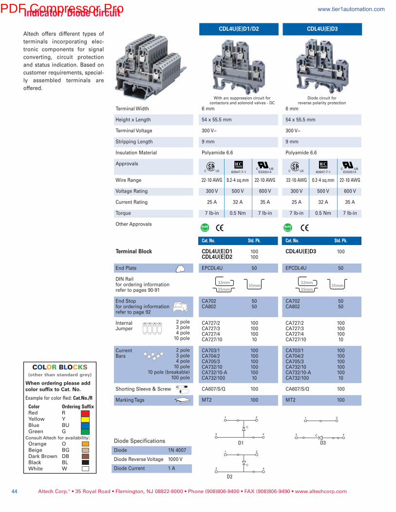
Diode Specifications
Diode 1N 4007
Diode Reverse Voltage 1000 V
Diode Current 1 A
1
3 4
C
2
1
3 4
C
2
1
3 4C
2
D1
D2
D3
CDL4U(E)D1/D2 CDL4U(E)D3
6 mm
54 x 55.5 mm
300 V~
9 mm
Polyamide 6.6
22-10AWG 0.2-4sq.mm 22-10AWG
300 V 500 V 600 V
25 A 32 A 35 A
7 lb-in 0.5 Nm 7 lb-in
Cat.No. Std.Pk. CDL4U(E)D3 100
EPCDL4U 50
CA702 50CA802 50
CA727/2 100CA727/3 100CA727/4 100CA727/10 10
CA703/1 100CA704/2 100CA705/3 100CA732/10 100CA732/10-A 100CA732/100 10
CA607/S/Q 100
MT2 100
6 mm
54 x 55.5 mm
300 V~
9 mm
Polyamide 6.6
22-10AWG 0.2-4sq.mm 22-10AWG
300 V 500 V 600 V
25 A 32 A 35 A
7 lb-in 0.5 Nm 7 lb-in
Cat.No. Std.Pk.
CDL4U(E)D1 100CDL4U(E)D2 100
EPCDL4U 50
CA702 50CA802 50
CA727/2 100CA727/3 100CA727/4 100CA727/10 10
CA703/1 100CA704/2 100CA705/3 100CA732/10 100CA732/10-A 100CA732/100 10
CA607/S/Q 100
MT2 100
Witharcsuppressioncircuitforcontactorsandsolenoidvalves-DC
Diodecircuitforreversepolarityprotection
Altech offers different types of
terminals incorporating elec-
tronic components for signal
converting, circuit protection
and status indication. Based on
customer requirements, special-
ly assembled terminals are
offered.
E220514 E220514
Altech Corp.® • 35 Royal Road • Flemington, NJ 08822-6000 • Phone (908)806-9400 • FAX (908)806-9490 • www.altechcorp.com44
Terminal Width
Height x Length
Terminal Voltage
Stripping Length
Insulation Material
Approvals
Wire Range
Voltage Rating
Current Rating
Torque
Other Approvals
Terminal Block
End Plate
DIN Railfor ordering informationrefer to pages 90-91
End Stopfor ordering informationrefer to page 92
InternalJumper
CurrentBars
Shorting Sleeve & Screw
Marking Tags
2 pole3 pole4 pole10 pole
2 pole3 pole4 pole10 pole
10 pole (breakable)100 pole
Indicator/DiodeCircuit
COLOR BLOCKS(otherthanstandardgrey)
When ordering please addcolor suffix to Cat. No.
ExampleforcolorRed:Cat.No./R
Color OrderingSuffixRed R
Yellow Y
Blue BU
Green G
ConsultAltechforavailability:Orange O
Beige BG
Dark Brown DB
Black BL
White W
60947-7-1 60947-7-1
PDF Compressor Pro www.tier1automation.com

1
3 C
C
C
C
+4
2
1
3 -4
2
1
+3
C C
C C
+4
2
1 2
+3 +4
1
3 +4
2
C
1
3 +4
CC
2
DD3DD1
DD2 DD4
D4 DD5
Altech Corp.® • 35 Royal Road • Flemington, NJ 08822-6000 • Phone (908)806-9400 • FAX (908)806-9490 • www.altechcorp.com 45
6 mm
54 x 55.5 mm
300 V~
9 mm
Polyamide 6.6
22-10AWG 0.2-4sq.mm 22-10AWG
300 V 500 V 600 V
25 A 32 A 35 A
7 lb-in 0.5 Nm 7 lb-in
Cat.No. Std.Pk.
CDL4U(E)DD3 100CDL4U(E)DD4 100
EPCDL4U 50
CA702 50CA802 50
CA727/2 100CA727/3 100CA727/4 100CA727/10 10
CA703/1 100CA704/1 100CA705/1 100CA732/10 100CA732/10-A 100CA732/100 10
CA607/S/Q 100
MT2 100
6 mm
54 x 55.5 mm
300 V~
9 mm
Polyamide 6.6
22-10AWG 0.2-4sq.mm 22-10AWG
300 V 500 V 600 V
25 A 32 A 35 A
7 lb-in 0.5 Nm 7 lb-in
Cat.No. Std.Pk.
CDL4U(E)DD1 100CDL4U(E)DD2 100
EPCDL4U 50
CA702 50CA802 50
CA727/2 100CA727/3 100CA727/4 100CA727/10 10
CA703/1 100CA704/1 100CA705/1 100CA732/10 100CA732/10-A 100CA732/100 10
CA607/S/Q 100
MT2 100
CDL4U(E)DD1/DD2 CDL4U(E)DD3/DD4
Diodecircuitforlamptesting Diodecircuitforlamptesting
6 mm
54 x 55.5 mm
12V~/24 V~
9 mm
Polyamide 6.6
22-10AWG 0.2-4sq.mm 22-10AWG
300 V 500 V 600 V
25 A 32 A 35 A
7 lb-in 0.5 Nm 7 lb-in
Cat.No. Std.Pk.
CDL4U(E)DD5 100
EPCDL4U 50
CA702 50CA802 50
CA727/2 100CA727/3 100CA727/4 100CA727/10 10
CA703/1 100CA704/1 100CA705/1 100CA732/10 100CA732/10-A 100CA732/100 10
CA607/S/Q 100
MT2 100
6 mm
54 x 55.5 mm
12V~/24 V~
9 mm
Polyamide 6.6
22-10AWG 0.2-4sq.mm 22-10AWG
300 V 500 V 600 V
25 A 32 A 35 A
7 lb-in 0.5 Nm 7 lb-in
Cat.No. Std.Pk.
CDL4U(E)D4 100
EPCDL4U 50
CA702 50CA802 50
CA727/2 100CA727/3 100CA727/4 100CA727/10 10
CA703/1 100CA704/1 100CA705/1 100CA732/10 100CA732/10-A 100CA732/100 10
CA607/S/Q 100
MT2 100
CDL4U(E)D4 CDL4U(E)DD5
DiodecircuitforlamptestingwithLEDseriesresistance
DiodecircuitforlamptestingwithLEDseriesresistance
E220514 E220514 E220514 E220514
Indicator/DiodeCircuit
60947-7-1 60947-7-1 60947-7-1 60947-7-1
PDF Compressor Pro www.tier1automation.com
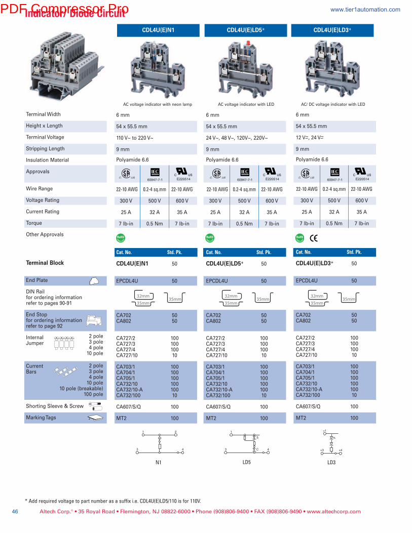
CDL4U(E)N1 CDL4U(E)LD5* CDL4U(E)LD3*
6 mm
54 x 55.5 mm
24 V~, 48 V~, 120V~, 220V~
9 mm
Polyamide 6.6
22-10AWG 0.2-4sq.mm 22-10AWG
300 V 500 V 600 V
25 A 32 A 35 A
7 lb-in 0.5 Nm 7 lb-in
Cat.No. Std.Pk.
CDL4U(E)LD5* 50
EPCDL4U 50
CA702 50CA802 50
CA727/2 100CA727/3 100CA727/4 100CA727/10 10
CA703/1 100CA704/1 100CA705/1 100CA732/10 100CA732/10-A 100CA732/100 10
CA607/S/Q 100
MT2 100
6 mm
54 x 55.5 mm
110 V~ to 220 V~
9 mm
Polyamide 6.6
22-10AWG 0.2-4sq.mm 22-10AWG
300 V 500 V 600 V
25 A 32 A 35 A
7 lb-in 0.5 Nm 7 lb-in
Cat.No. Std.Pk.
CDL4U(E)N1 50
EPCDL4U 50
CA702 50CA802 50
CA727/2 100CA727/3 100CA727/4 100CA727/10 10
CA703/1 100CA704/1 100CA705/1 100CA732/10 100CA732/10-A 100CA732/100 10
CA607/S/Q 100
MT2 100
ACvoltageindicatorwithneonlamp
6 mm
54 x 55.5 mm
12 V~, 24 V~
9 mm
Polyamide 6.6
22-10AWG 0.2-4sq.mm 22-10AWG
300 V 500 V 600 V
25 A 32 A 35 A
7 lb-in 0.5 Nm 7 lb-in
Cat.No. Std.Pk.
CDL4U(E)LD3* 50
EPCDL4U 50
CA702 50CA802 50
CA727/2 100CA727/3 100CA727/4 100CA727/10 10
CA703/1 100CA704/1 100CA705/1 100CA732/10 100CA732/10-A 100CA732/100 10
CA607/S/Q 100
MT2 100
AC/DCvoltageindicatorwithLEDACvoltageindicatorwithLED
1
3 4
2 1
3 4C +3 +4
+1
N1 LD5 LD3
*Addrequiredvoltagetopartnumberasasuffixi.e.CDL4U(E)LD5/110isfor110V.
E220514 E220514 E220514
Altech Corp.® • 35 Royal Road • Flemington, NJ 08822-6000 • Phone (908)806-9400 • FAX (908)806-9490 • www.altechcorp.com46
Terminal Width
Height x Length
Terminal Voltage
Stripping Length
Insulation Material
Approvals
Wire Range
Voltage Rating
Current Rating
Torque
Other Approvals
Terminal Block
End Plate
DIN Railfor ordering informationrefer to pages 90-91
End Stopfor ordering informationrefer to page 92
InternalJumper
CurrentBars
Shorting Sleeve & Screw
Marking Tags
2 pole3 pole4 pole10 pole
2 pole3 pole4 pole10 pole
10 pole (breakable)100 pole
Indicator/DiodeCircuit
60947-7-160947-7-1 60947-7-1
PDF Compressor Pro www.tier1automation.com
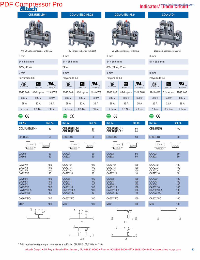
Altech Corp.® • 35 Royal Road • Flemington, NJ 08822-6000 • Phone (908)806-9400 • FAX (908)806-9490 • www.altechcorp.com 47
+1
-3 -4
-1
+3 +4
+1
-3
C
C
-4
-1
+3 +4
-1
+3 +4
C
L1LD1
LD2
6 mm
54 x 55.5 mm
24 V–
9 mm
Polyamide 6.6
22-10AWG 0.2-4sq.mm 22-10AWG
300 V 500 V 600 V
25 A 32 A 35 A
7 lb-in 0.5 Nm 7 lb-in
Cat.No. Std.Pk. CDL4U(E)LD1 50CDL4U(E)LD2 50
EPCDL4U 50
CA702 50CA802 50
CA727/2 100CA727/3 100CA727/4 100CA727/10 10
CA703/1 100CA704/1 100CA705/1 100CA732/10 100CA732/10-A 100CA732/100 10
CA607/S/Q 100
MT2 100
6 mm
54 x 55.5 mm
24V~, 48 V~
9 mm
Polyamide 6.6
22-10AWG 0.2-4sq.mm 22-10AWG
300 V 500 V 600 V
25 A 32 A 35 A
7 lb-in 0.5 Nm 7 lb-in
Cat.No. Std.Pk.
CDL4U(E)LD4* 50
EPCDL4U 50
CA702 50CA802 50
CA727/2 100CA727/3 100CA727/4 100CA727/10 10
CA703/1 100CA704/1 100CA705/1 100CA732/10 100CA732/10-A 100CA732/100 10
CA607/S/Q 100
MT2 100
CDL4U(E)LD4* CDL4U(E)LD1/LD2
AC/DCvoltageindicatorwithLED
6 mm
54 x 55.5 mm
6 V–, 24 V–, 60 V–
9 mm
Polyamide 6.6
22-10AWG 0.2-4sq.mm 22-10AWG
300 V 500 V 600 V
25 A 32 A 35 A
7 lb-in 0.5 Nm 7 lb-in
Cat.No. Std.Pk.
CDL4U(E)L1* 50CDL4U(E)L2* 50
EPCDL4U 50
CA702 50CA802 50
CA727/2 100CA727/3 100CA727/4 100CA727/10 10
CA703/1 100CA704/1 100CA705/1 100CA732/10 100CA732/10-A 100CA732/100 10
CA607/S/Q 100
MT2 100
CDL4U(E)L1/L2* CDL4U(O)
DCvoltageindicatorwithLED ElectronicComponentCarrierDCvoltageindicatorwithLED
6 mm
54 x 55.5 mm
9 mm
Polyamide 6.6
22-10AWG 0.2-4sq.mm 22-10AWG
300 V 500 V 600 V
25 A 32 A 35 A
7 lb-in 0.5 Nm 7 lb-in
Cat.No. Std.Pk. CDL4U(O) 100
EPCDL4U 50
CA702 50CA802 50
CA727/2 100CA727/3 100CA727/4 100CA727/10 10
CA703/1 100CA704/1 100CA705/1 100CA732/10 100CA732/10-A 100CA732/100 10
CA607/S/Q 100
MT2 100
L2
E220514 E220514 E220514 E220514
Indicator/DiodeCircuit
*Addrequiredvoltagetopartnumberasasuffixi.e.CDL4U(E)LD5/110isfor110V.
60947-7-1 60947-7-1 60947-7-1 60947-7-1
PDF Compressor Pro www.tier1automation.com
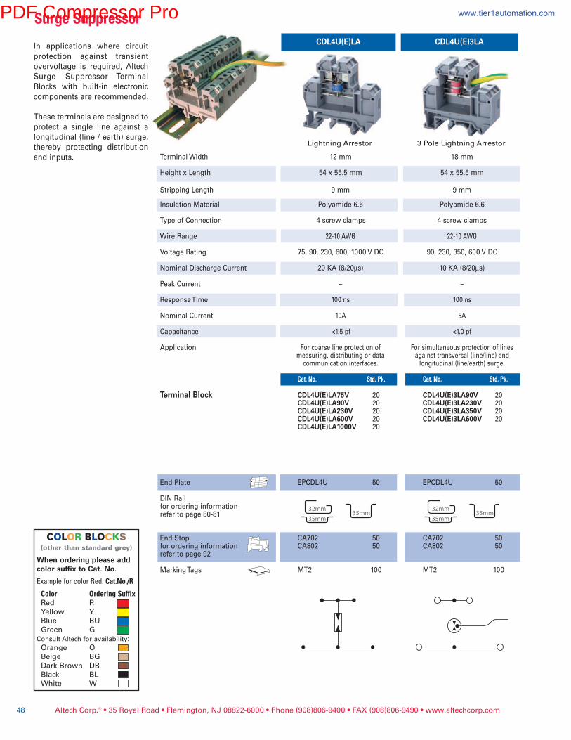
CDL4U(E)LA CDL4U(E)3LA
Terminal Width
Height x Length
Stripping Length
Insulation Material
Type of Connection
Wire Range
Voltage Rating
Nominal Discharge Current
Peak Current
Response Time
Nominal Current
Capacitance
Application
Terminal Block
End Plate
DIN Railfor ordering informationrefer to page 80-81
End Stopfor ordering informationrefer to page 92
Marking Tags
12 mm 54 x 55.5 mm
9 mm
Polyamide 6.6
4 screw clamps
22-10AWG
75, 90, 230, 600, 1000 V DC
20 KA (8/20µs)
–
100 ns
10A
<1.5 pf
For coarse line protection of measuring, distributing or data communication interfaces.
Cat.No. Std.Pk.
CDL4U(E)LA75V 20CDL4U(E)LA90V 20CDL4U(E)LA230V 20CDL4U(E)LA600V 20CDL4U(E)LA1000V 20
EPCDL4U 50
CA702 50CA802 50
MT2 100
18 mm 54 x 55.5 mm
9 mm
Polyamide 6.6
4 screw clamps
22-10AWG
90, 230, 350, 600 V DC
10 KA (8/20µs)
–
100 ns
5A
<1.0 pf
For simultaneous protection of linesagainst transversal (line/line) andlongitudinal (line/earth) surge.
Cat.No. Std.Pk.
CDL4U(E)3LA90V 20CDL4U(E)3LA230V 20CDL4U(E)3LA350V 20CDL4U(E)3LA600V 20
EPCDL4U 50
CA702 50CA802 50
MT2 100
LightningArrestor 3PoleLightningArrestor
Altech Corp.® • 35 Royal Road • Flemington, NJ 08822-6000 • Phone (908)806-9400 • FAX (908)806-9490 • www.altechcorp.com48
In applications where circuit
protection against transient
overvoltage is required, Altech
Surge Suppressor Terminal
Blocks with built-in electronic
components are recommended.
These terminals are designed to
protect a single line against a
longitudinal (line / earth) surge,
thereby protecting distribution
and inputs.
SurgeSuppressor
COLOR BLOCKS(otherthanstandardgrey)
When ordering please addcolor suffix to Cat. No.
ExampleforcolorRed:Cat.No./R
Color OrderingSuffixRed R
Yellow Y
Blue BU
Green G
ConsultAltechforavailability:Orange O
Beige BG
Dark Brown DB
Black BL
White W
PDF Compressor Pro www.tier1automation.com
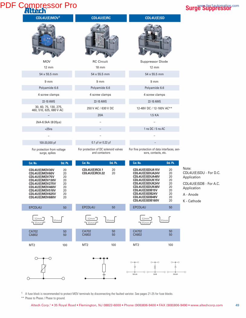
Altech Corp.® • 35 Royal Road • Flemington, NJ 08822-6000 • Phone (908)806-9400 • FAX (908)806-9490 • www.altechcorp.com 49
SDBSDUA SDUK
CDL4U(E)MOV1 CDL4U(E)SDCDL4U(E)RC
12 mm 54 x 55.5 mm
9 mm
Polyamide 6.6
4 screw clamps
22-10AWG
12-48V DC / 12-160V AC**
1.5 KA
–
1 ns DC / 5 ns AC
–
–
For fine protection of data interfaces, sen-sors, contacts, etc.
Cat.No. Std.Pk.
CDL4U(E)SDUA15V 20CDL4U(E)SDUA24V 20CDL4U(E)SDUA48V 20CDL4U(E)SDUK15V 20CDL4U(E)SDUK24V 20CDL4U(E)SDUK48V 20CDL4U(E)SDB15V 20CDL4U(E)SDB24V 20CDL4U(E)SDB48V 20CDL4U(E)SDB160V 20
EPCDL4U 50
CA702 50CA802 50
MT2 100
18 mm 54 x 55.5 mm
9 mm
Polyamide 6.6
4 screw clamps
22-10AWG
250 V AC / 630 V DC
20A
–
–
–
0.1 µf or 0.22 µf
For protection of DC solenoid valvesand contactors
Cat.No. Std.Pk.
CDL4U(E)RC0.1 20CDL4U(E)RC0.22 20
EPCDL4U 50
CA702 50CA802 50
MT2 100
12 mm 54 x 55.5 mm
9 mm
Polyamide 6.6
4 screw clamps
22-10AWG
30, 60, 75, 130, 275,460, 510, 625, 680 V AC
–
2kA-6.5kA (8/20µs)
<25ns
–
100-20,000 pf
For protection from voltagesurge, spikes
Cat.No. Std.Pk. CDL4U(E)MOV30V 20 CDL4U(E)MOV60V 20 CDL4U(E)MOV75V 20 CDL4U(E)MOV130V 20 CDL4U(E)MOV275V 20 CDL4U(E)MOV460V 20 CDL4U(E)MOV510V 20 CDL4U(E)MOV625V 20 CDL4U(E)MOV680V 20
EPCDL4U 50
CA702 50
CA802 50
MT2 100
MOV SuppressorDiodeRCCircuit
1 AfuseblockisrecommendedtoprotectMOVterminalsbydisconnectingthefaultedvaristor.Seepages21-25forfuseblocks.** PhasetoPhase/Phasetoground.
Note:
CDL4U(E)SDU - For D.C.
Application
CDL4U(E)SDB - For A.C.
Application
A - Anode
K - Cathode
SurgeSuppressorPDF Compressor Pro www.tier1automation.com
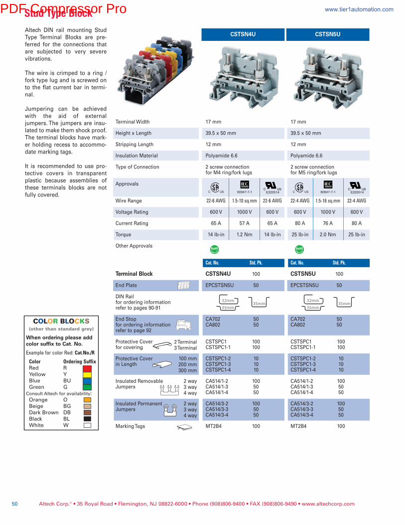
CSTSN4U CSTSN5U
Terminal Width
Height x Length
Stripping Length
Insulation Material
Type of Connection
Approvals
Wire Range
Voltage Rating
Current Rating
Torque
Other Approvals
Terminal Block
End Plate
DIN Railfor ordering informationrefer to pages 90-91
End Stopfor ordering informationrefer to page 92
Protective Coverfor covering
Protective Coverin Length
Insulated RemovableJumpers
Insulated PermanentJumpers
Marking Tags
2 Terminal3 Terminal
100 mm200 mm300 mm
2 way3 way4 way
2 way3 way4 way
17 mm
39.5 x 50 mm
12 mm
Polyamide 6.6
2 screw connectionfor M4 ring/fork lugs
22-6AWG 1.5-10sq.mm 22-6AWG
600 V 1000 V 600 V
65 A 57 A 65 A
14 lb-in 1.2 Nm 14 lb-in
Cat.No. Std.Pk.
CSTSN4U 100
EPCSTSN5U 50
CA702 50CA802 50
CSTSPC1 100CSTSPC1-1 100
CSTSPC1-2 10CSTSPC1-3 10CSTSPC1-4 10
CA514/1-2 100CA514/1-3 50CA514/1-4 50
CA514/3-2 100CA514/3-3 50CA514/3-4 50
MT2B4 100
Altech DIN rail mounting Stud
Type Terminal Blocks are pre-
ferred for the connections that
are subjected to very severe
vibrations.
The wire is crimped to a ring /
fork type lug and is screwed on
to the flat current bar in termi-
nal.
Jumpering can be achieved
with the aid of external
jumpers. The jumpers are insu-
lated to make them shock proof.
The terminal blocks have mark-
er holding recess to accommo-
date marking tags.
It is recommended to use pro-
tective covers in transparent
plastic because assemblies of
these terminals blocks are not
fully covered.
17 mm
39.5 x 50 mm
12 mm
Polyamide 6.6
2 screw connectionfor M5 ring/fork lugs
22-4AWG 1.5-16sq.mm 22-4AWG
600 V 1000 V 600 V
80 A 76 A 80 A
25 lb-in 2.0 Nm 25 lb-in
Cat.No. Std.Pk.
CSTSN5U 100
EPCSTSN5U 50
CA702 50CA802 50
CSTSPC1 100CSTSPC1-1 100
CSTSPC1-2 10CSTSPC1-3 10CSTSPC1-4 10
CA514/1-2 100CA514/1-3 50CA514/1-4 50
CA514/3-2 100CA514/3-3 50CA514/3-4 50
MT2B4 100
Altech Corp.® • 35 Royal Road • Flemington, NJ 08822-6000 • Phone (908)806-9400 • FAX (908)806-9490 • www.altechcorp.com50
E220514 E220514
StudTypeBlock
COLOR BLOCKS(otherthanstandardgrey)
When ordering please addcolor suffix to Cat. No.
ExampleforcolorRed:Cat.No./R
Color OrderingSuffixRed R
Yellow Y
Blue BU
Green G
ConsultAltechforavailability:Orange O
Beige BG
Dark Brown DB
Black BL
White W
60947-7-1 60947-7-1
PDF Compressor Pro www.tier1automation.com
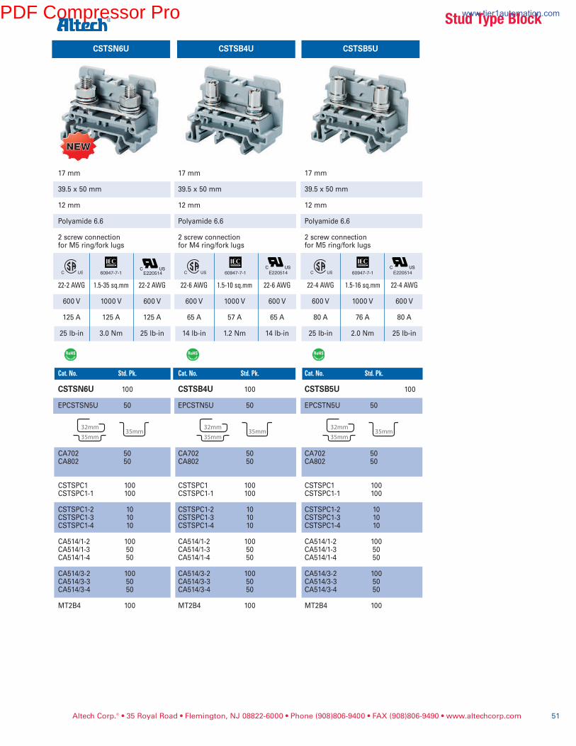
Altech Corp.® • 35 Royal Road • Flemington, NJ 08822-6000 • Phone (908)806-9400 • FAX (908)806-9490 • www.altechcorp.com 51
CSTSB4U CSTSB5U
17 mm
39.5 x 50 mm
12 mm
Polyamide 6.6
2 screw connectionfor M4 ring/fork lugs
22-6AWG 1.5-10sq.mm 22-6AWG
600 V 1000 V 600 V
65 A 57 A 65 A
14 lb-in 1.2 Nm 14 lb-in
Cat.No. Std.Pk.
CSTSB4U 100
EPCSTN5U 50
CA702 50CA802 50
CSTSPC1 100CSTSPC1-1 100
CSTSPC1-2 10CSTSPC1-3 10CSTSPC1-4 10
CA514/1-2 100CA514/1-3 50CA514/1-4 50
CA514/3-2 100CA514/3-3 50CA514/3-4 50
MT2B4 100
17 mm
39.5 x 50 mm
12 mm
Polyamide 6.6
2 screw connectionfor M5 ring/fork lugs
22-4AWG 1.5-16sq.mm 22-4AWG
600 V 1000 V 600 V
80 A 76 A 80 A
25 lb-in 2.0 Nm 25 lb-in
Cat.No. Std.Pk.
CSTSB5U 100
EPCSTN5U 50
CA702 50CA802 50
CSTSPC1 100CSTSPC1-1 100
CSTSPC1-2 10CSTSPC1-3 10CSTSPC1-4 10
CA514/1-2 100CA514/1-3 50CA514/1-4 50
CA514/3-2 100CA514/3-3 50CA514/3-4 50
MT2B4 100
E220514 E220514
StudTypeBlock
CSTSN6U
17 mm
39.5 x 50 mm
12 mm
Polyamide 6.6
2 screw connectionfor M5 ring/fork lugs
22-2AWG 1.5-35sq.mm 22-2AWG
600 V 1000 V 600 V
125 A 125 A 125 A
25 lb-in 3.0 Nm 25 lb-in
Cat.No. Std.Pk.
CSTSN6U 100
EPCSTSN5U 50
CA702 50CA802 50
CSTSPC1 100CSTSPC1-1 100
CSTSPC1-2 10CSTSPC1-3 10CSTSPC1-4 10
CA514/1-2 100CA514/1-3 50CA514/1-4 50
CA514/3-2 100CA514/3-3 50CA514/3-4 50
MT2B4 100
E220514
NEWNEW
60947-7-1 60947-7-1 60947-7-1
PDF Compressor Pro www.tier1automation.com
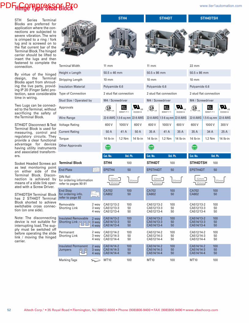
Terminal Width
Height x Length
Stripping Length
Insulation Material
Type of Connection
Stud Size / Operated by
Approvals
Wire Range
Voltage Rating
Current Rating
Torque
Other Approvals
�erminal Block
End Plate
DIN Railfor ordering informationrefer to pages 90-91
End Stopfor ordering info.refer to page 92
RemovableShorting Link
Insulated RemovableShorting Link
PermanantShorting Link
Insulated PermanentJumpers
Marking Tags
2 way3 way4 way
2 way3 way4 way
2 way3 way4 way
2 way3 way4 way
11 mm
50.5 x 46 mm
10 mm
Polyamide 6.6
2 stud flat connection
M4 / Screwdriver
22-8AWG 1.5-6sq.mm 22-8AWG
600 V 1000 V 600 V
50 A 41 A 50 A
14 lb-in 1.2 Nm 14 lb-in
Cat.No. Std.Pk.
STH4 100
EPSTH4 50
CA702 100CA802 50
CA512/13-2 100CA512/13-3 50CA512/13-4 50
CA514/13-2 100CA514/13-3 50CA514/13-4 50
CA512/14-2 100CA512/14-3 50CA512/14-4 50
CA514/14-2 100CA514/14-3 50CA514/14-4 50
MT10 100
Altech Corp.® • 35 Royal Road • Flemington, NJ 08822-6000 • Phone (908)806-9400 • FAX (908)806-9490 • www.altechcorp.com52
STH4
11 mm
50.5 x 86 mm
10 mm
Polyamide 6.6
2 stud flat connection
M4 / Screwdriver
22-8AWG 1.5-6sq.mm 22-8AWG
600 V 1000 V 600 V
35 A 41 A 35 A
14 lb-in 1.2 Nm 14 lb-in
Cat.No. Std.Pk.
STH4DT 100
EPSTH4DT 50
CA702 100CA802 50
CA512/13-2 100CA512/13-3 50CA512/13-4 50
CA514/13-2 100CA514/13-3 50CA514/13-4 50
CA512/14-2 100CA512/14-3 50CA512/14-4 50
CA514/14-2 100CA514/14-3 50CA514/14-4 50
MT10 100
STH4DT
22 mm
50.5 x 86 mm
10 mm
Polyamide 6.6
2 stud flat connection
M4 / Screwdriver
22-8AWG 1.5-6sq.mm 22-8AWG
600 V 1000 V 300 V
35 A 34 A 25 A
14 lb-in 1.2 Nm 14 lb-in
Cat.No. Std.Pk.
STH4DTSH 100
EPSTH4DT 50
CA702 100CA802 50
CA512/13-2 100CA512/13-3 50CA512/13-4 50
CA514/13-2 100CA514/13-3 50CA514/13-4 50
CA512/14-2 100CA512/14-3 50CA512/14-4 50
CA514/14-2 100CA514/14-3 50CA514/14-4 50
MT10 100
STH4DTSHSTH Series TerminalBlocks are preferred forapplication where the con-nections are subjected tosevere vibration. The wireis crimped to a ring / forklug and is screwed on tothe flat current bar of theTerminal Block. The hingedcarrier should be lifted toinsert the lugs and thenfastened to complete theconnection.
By virtue of the hingeddesign, the TerminalBlocks apart from shroud-ing the live parts, provid-ing IP 20 (Finger Safe) pro-tection, save considerabletime in wiring.
Two Lugs can be connect-ed to the Terminal, withoutsacrificing the safety ofthe Terminal Block.
STH4DT Disconnect & TestTerminal Block is used formeasuring, control andregulatory circuits. Theyprovide a clear functionaladvantage for deviceshaving utility instrumentsand associated transform-ers.
Socket Headed Screws actas test monitoring pointon either side of theTerminal Block. Discon-nection is achieved bymeans of a slide link oper-ated with a Screw Driver.
STH4DTSH Terminal Blockhas 2 STH4DT TerminalBlock shorted to achieveswitchable cross connec-tion (on one side).
Note: The disconnectingdevice is not suitable forinterrupting load. The sup-ply must be switched offbefore operating the slidelink / moving the hingedcarrier.
HingeTypeStudBlock
E220514 E220514 E22051460947-7-1 60947-7-1 60947-7-1
PDF Compressor Pro www.tier1automation.com
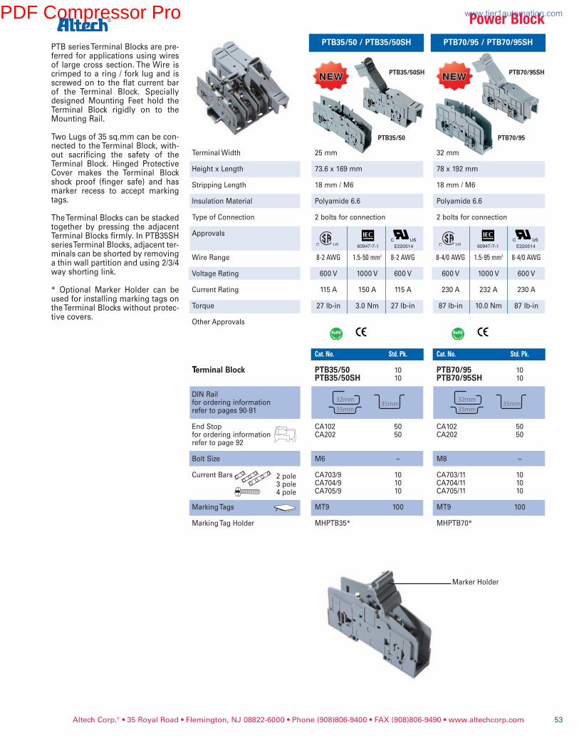
Altech Corp.® • 35 Royal Road • Flemington, NJ 08822-6000 • Phone (908)806-9400 • FAX (908)806-9490 • www.altechcorp.com 53
Terminal Width
Height x Length
Stripping Length
Insulation Material
Type of Connection
Approvals
Wire Range
Voltage Rating
Current Rating
Torque
Other Approvals
�erminal Block
DIN Railfor ordering informationrefer to pages 90-91
End Stopfor ordering informationrefer to page 92
Bolt Size
Current Bars
Marking Tags
Marking Tag Holder
2 pole3 pole4 pole
32 mm
78 x 192 mm
18 mm / M6
Polyamide 6.6
2 bolts for connection
8-4/0AWG 1.5-95mm2 8-4/0AWG
600 V 1000 V 600 V
230 A 232 A 230 A
87 lb-in 10.0 Nm 87 lb-in
Cat.No. Std.Pk.
PTB70/95 10PTB70/95SH 10
CA102 50CA202 50
M8 –
CA703/11 10CA704/11 10CA705/11 10
MT9 100
MHPTB70*
PTB70/95 / PTB70/95SHPTB series Terminal Blocks are pre-ferred for applications using wiresof large cross section. The Wire iscrimped to a ring / fork lug and isscrewed on to the flat current barof the Terminal Block. Speciallydesigned Mounting Feet hold theTerminal Block rigidly on to theMounting Rail.
Two Lugs of 35 sq.mm can be con-nected to the Terminal Block, with-out sacrificing the safety of theTerminal Block. Hinged ProtectiveCover makes the Terminal Blockshock proof (finger safe) and hasmarker recess to accept markingtags.
The Terminal Blocks can be stackedtogether by pressing the adjacentTerminal Blocks firmly. In PTB35SHseries Terminal Blocks, adjacent ter-minals can be shorted by removinga thin wall partition and using 2/3/4way shorting link.
* Optional Marker Holder can beused for installing marking tags onthe Terminal Blocks without protec-tive covers.
Marker Holder
PowerBlock
25 mm
73.6 x 169 mm
18 mm / M6
Polyamide 6.6
2 bolts for connection
8-2AWG 1.5-50mm2 8-2AWG
600 V 1000 V 600 V
115 A 150 A 115 A
27 lb-in 3.0 Nm 27 lb-in
Cat.No. Std.Pk.
PTB35/50 10PTB35/50SH 10
CA102 50CA202 50
M6 –
CA703/9 10CA704/9 10CA705/9 10
MT9 100
MHPTB35*
PTB35/50 / PTB35/50SH
PTB35/50SH PTB70/95SH
PTB35/50 PTB70/95
NEWNEW NEWNEW
E22051460947-7-1 E22051460947-7-1
PDF Compressor Pro www.tier1automation.com