
PDF (3.72 MB) - IOPscience
20
OPEN ACCESS A versatile fabrication method for cluster superlattices To cite this article: Alpha T N'Diaye et al 2009 New J. Phys. 11 103045 View the article online for updates and enhancements. You may also like Lattice thermal conductivity in isotope diamond asymmetric superlattices Hsu Kai Weng, Akira NAGAKUBO, Hideyuki Watanabe et al. - Preparation and Dielectric Properties of SrZrO 3 /SrTiO 3 Superlattices Takakiyo Harigai, Daisuke Tanaka, Song- Min Nam et al. - Efficient Hole Generation above 10 19 cm -3 in Mg-Doped InGaN/GaN Superlattices at Room Temperature Kazuhide Kumakura, Toshiki Makimoto and Naoki Kobayashi - Recent citations Built-up AFM tips by metal nanoclusters engineering Mariano D. Jiménez-Sánchez et al - Growth, Stability, and Electronic Decoupling of Pt Clusters on h-BN/Ir(111) Moritz Will et al - Reversible disorder-order transitions in atomic crystal nucleation Sungho Jeon et al - This content was downloaded from IP address 177.34.55.189 on 01/01/2022 at 02:53
Transcript of PDF (3.72 MB) - IOPscience
OPEN ACCESS
A versatile fabrication method for clustersuperlatticesTo cite this article: Alpha T N'Diaye et al 2009 New J. Phys. 11 103045
View the article online for updates and enhancements.
You may also likeLattice thermal conductivity in isotopediamond asymmetric superlatticesHsu Kai Weng, Akira NAGAKUBO,Hideyuki Watanabe et al.
-
Preparation and Dielectric Properties ofSrZrO3/SrTiO3 SuperlatticesTakakiyo Harigai, Daisuke Tanaka, Song-Min Nam et al.
-
Efficient Hole Generation above 1019 cm-3
in Mg-Doped InGaN/GaN Superlattices atRoom TemperatureKazuhide Kumakura, Toshiki Makimotoand Naoki Kobayashi
-
Recent citationsBuilt-up AFM tips by metal nanoclustersengineeringMariano D. Jiménez-Sánchez et al
-
Growth, Stability, and ElectronicDecoupling of Pt Clusters on h-BN/Ir(111)Moritz Will et al
-
Reversible disorder-order transitions inatomic crystal nucleationSungho Jeon et al
-
This content was downloaded from IP address 177.34.55.189 on 01/01/2022 at 02:53

T h e o p e n – a c c e s s j o u r n a l f o r p h y s i c s
New Journal of Physics
A versatile fabrication method for clustersuperlattices
Alpha T N’Diaye1,3, Timm Gerber1, Carsten Busse1,Josef Myslivecek2, Johann Coraux1,4 and Thomas Michely1
1 II. Physikalisches Institut, Universität zu Köln, Zülpicher Straße 77,50937 Köln, Germany2 Charles University, Faculty of Mathematics and Physics, V Holesovickách 2,180 00 Praha 8, Czech RepublicE-mail: [email protected]
New Journal of Physics 11 (2009) 103045 (19pp)Received 29 July 2009Published 26 October 2009Online at http://www.njp.org/doi:10.1088/1367-2630/11/10/103045
Abstract. On the graphene moiré on Ir(111) a variety of highly perfect clustersuperlattices can be grown as shown for Ir, Pt, W and Re. Even materials that donot form cluster superlattices upon room temperature deposition may be growninto such by low-temperature deposition or the application of cluster seedingthrough Ir as shown for Au, AuIr and FeIr. Criteria for the suitability of a materialto form a superlattice are given and largely confirmed. It is proven that at least Ptand Ir form epitaxial cluster superlattices. The temperature stability of the clustersuperlattices is investigated and understood on the basis of positional fluctuationsof the clusters around their sites of minimum potential energy. The binding sitesof Ir, Pt, W and Re cluster superlattices are determined and the ability to coversamples macroscopically with a variety of superlattices is demonstrated.
3 Author to whom any correspondence should be addressed.4 Permanent address: Institut Néel/CNRS, Bât. D, 25 Rue des Martyrs, F-38042 Grenoble Cedex 9, France.
New Journal of Physics 11 (2009) 1030451367-2630/09/103045+19$30.00 © IOP Publishing Ltd and Deutsche Physikalische Gesellschaft
2
Contents
1. Introduction 22. Experimental 53. Results 5
3.1. Cluster structure and superlattice formation at 300 K . . . . . . . . . . . . . . 53.2. Low-temperature cluster superlattice growth and annealing . . . . . . . . . . . 83.3. Cluster seeding . . . . . . . . . . . . . . . . . . . . . . . . . . . . . . . . . . 103.4. Temperature stability . . . . . . . . . . . . . . . . . . . . . . . . . . . . . . . 103.5. Binding sites of clusters in the superlattice . . . . . . . . . . . . . . . . . . . . 153.6. Toward cluster superlattice materials . . . . . . . . . . . . . . . . . . . . . . . 16
4. Conclusion 17Acknowledgments 18References 18
1. Introduction
Clusters are a distinct state of matter. Not only do their structure, electronic, magnetic andoptical properties change with size, but also new properties emerge as a result of quantizationeffects unknown in the atom and the bulk solid [1]. Well-known examples for unique clusterproperties are magic sizes in geometric and electronic structure, superparamagnetism, plasmonresonances or size-dependent reactivity [2]–[4]. Although cluster properties may be studiedin their purest form for mass-selected clusters in the free beam, the use of clusters requiresa suitable support [5]. Ideally, a system of supported clusters is a regular array with equallysized and spaced clusters, each in an identical environment and of macroscopic array extension.The cluster bonding to the substrate should be strong enough to warrant their stability at thetemperature of operation and weak enough not to destroy them as entities in themselves. Thesubstrate should be inert in the sense that it does not deteriorate under the condition of usebut active enough to bestow new functionalities to the clusters without destroying them. Sucharrays or cluster superlattices would allow one to address single clusters (as might, e.g. be ofinterest for magnetic applications), to obtain a large amplitude of response resulting from theadditive superposition of all single clusters and characteristic for a cluster of well-defined size ina specific environment (as, e.g. needed in catalysis), or to obtain a collective coherent responsecharacteristic of a large interacting ensemble of clusters (as, e.g. in optics).
This vision triggered attempts to make use of self-organization and/or templates forthe creation of cluster superlattices and a few examples are given here (compare also [6]).By making use of the regular arrangement of steps on vicinal Au(111) and its herringbonereconstruction crossing the steps at right angles a proper Co cluster superlattice could berealized [7], enabling the measurement of its temperature-dependent magnetic propertiesincluding the distribution of cluster magnetic anisotropy energies [8]. Also Fe could be grownregularly [9], but the method is limited by its low growth temperature and strong clustersubstrate interaction giving rise to alloying. Alumina double layers on Ni3Al(111) exhibit aphase with a regular superlattice of sites for nucleation upon metal deposition [10], whichare holes in the oxide [11]. Cluster superlattices were realized for a variety of metals at roomtemperature [10, 12, 13] and a high perfection was achieved for Pd [10]. Although such cluster
New Journal of Physics 11 (2009) 103045 (http://www.njp.org/)

3
lattices appear to be suited as model catalysts, the preparation of the alumina layer is the resultof a subtle procedure, comprises defects and at least two phases of alumina with limited domainsizes, of which only one is suitable as a template [11]. Recently, Xe buffer layer-assisted self-assembly of Co on a BN layer forming a moiré with Rh(111) was achieved [14]. Although theplacement of the Co clusters is regular, the method is hampered by the very low temperatureof fabrication, the limited thermal stability and the only incomplete filling of the template cells.As a final example, on the W(110)/C-R(15 × 12) surface carbide arrangements of Au, Ag andCo clusters could be grown, the latter two with a high degree of order [15, 16]. Although thethermal stability of the arrangements is rather good, no macroscopic extension of a superlatticeis achieved due to the persistent existence of terraces without the surface carbide.
Graphene moirés with noble metal surfaces are a new and unique support for clustersuperlattices. This was shown first for graphene moirés on Ir(111) allowing Ir cluster superlatticeformation [17]. Although a special material system, the binding mechanism is versatile.Through metal deposition on the graphene layer—which is only weakly interacting with themetal substrate in the absence of metal deposits [18]—graphene locally rehybridizes from sp2
to sp3 carbon bonds at a specific location in the moiré unit cell and in between the substrateand deposit metal, thereby forming strong carbon metal bonds [19]. In between the substrateand deposit metal the sp3 rehybridized graphene has tetrahedral bond angles and may thusbe considered as diamond-like. Within each moiré unit cell rehybridization is possible wherelocally the carbon rings center around a threefold coordinated hcp-site or a threefold coordinatedfcc-site (both having three C-atoms atop substrate sites). These locations are named the hcpregion and fcc region, respectively. Experimentally and by DFT calculations, we find that Irclusters bind much more strongly to hcp regions [17, 19, 20]. This collaborative effect includinggraphene-mediated interaction with the substrate distinguishes the binding mechanism on themoiré from the binding of adatoms or small clusters on freestanding graphene [21, 22].
Figure 1(a) displays a cluster superlattice grown on a graphene flake formed bytemperature-programmed growth (TPG) on Ir(111) [23]. With this method graphene coversthe surface only partially, which is suitable for scanning probe investigations, as it retains themetal surface partially for calibration of cluster size through island coverage in the graphene-free areas. Also direct comparison of the properties of clusters and those of the depositislands on the metal is possible. Recently, we employed chemical vapor deposition (CVD)at high temperatures to grow graphene fully covering the substrate and displaying hardly anydefects [23, 24]. Using a dedicated combination of both methods [25], we are not only able toensure full coverage but also the graphene and Ir dense packed atomic rows to be parallel, i.e.no traces of rotational variants are present [26].
In this paper, we will show that graphene moirés as active templates are superior to othersystems enabling the growth of two-dimensional cluster superlattices on solid surfaces througha unique combination of properties: (i) the cluster-binding mechanism is universal enablinggrowth of a large diversity of materials as superlattice; (ii) the superlattice order is extremelyhigh with a completely filled lattice; (iii) if desired the superlattice extends macroscopicallywithout uncovered substrate patches; (iv) fabrication is possible at room temperature; (v) thesuperlattices possess a reasonably high thermal stability and display absence of alloying andinterdiffusion within a large temperature range; and (vi) the cluster size is tunable and the sizedistribution is narrow.
To demonstrate the universality of our approach in view of superlattice-forming materialswe primarily focused on cluster materials with potentially interesting structural, magnetic,
New Journal of Physics 11 (2009) 103045 (http://www.njp.org/)

4
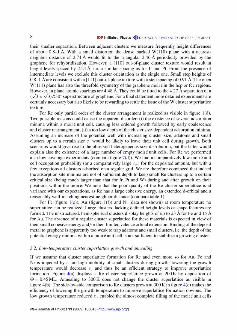
Figure 1. STM topographs of Ir(111) with graphene flakes after deposition ofan amount 2 of various metals at 300 K. (a) 2 = 0.20 ML Ir, average clustersize sav = 17 atoms; (b) 2 = 0.25 ML Pt, sav = 22 atoms; (c) 2 = 0.44 ML W,sav = 38 atoms; (d) 2 = 0.53 ML Re, sav = 60 atoms; (e) 2 = 0.77 ML Fe, sav =
420 atoms; (f) 2 = 0.25 ML Au, sav = 100 atoms. Image size 700 Å × 700 Å.
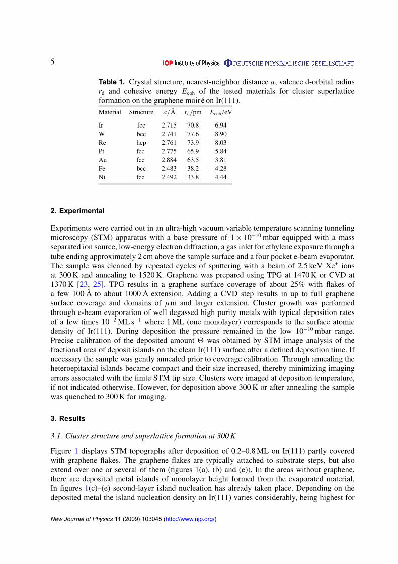
catalytic or optical properties. As heuristic guidelines for the suitability of a material to forma superlattice we considered three factors. (i) A large cohesive strength of the material as anindicator for the ability to form strong bonds. (ii) A large extension of a localized valenceorbital of the deposit material allows it to efficiently interact with the graphene π -bond and thusto initiate rehybridization to diamond-like carbon underneath the cluster. (iii) A certain matchof the graphene unit cell repeat distance on Ir(111) of 2.452 Å [20] and the nearest-neighbordistance of the deposit material is necessary to fit the first layer cluster atoms atop every secondC atom. As small clusters—which are the relevant sizes to start superlattice growth—have asmaller lattice parameter compared with bulk materials, and as Ir works perfectly as a clustermaterial [17], we considered 2.7 Å as an optimal nearest-neighbor distance. Table 1 comparesthe data for the tested materials. Tungsten was selected as a likely candidate for superlatticeformation (all three figures support the superlattice formation), but with a different crystalstructure than Ir. Re, Pt and Au were selected as potentially interesting materials for catalysis.According to our guidelines we expected Re to be most likely a superlattice-forming material(also Pt) but with a slightly smaller probability and Au as an unlikely candidate. Fe and Niwere selected as materials because of their ferromagnetism. According to their figures of merit,however, we did not expect superlattice formation.
New Journal of Physics 11 (2009) 103045 (http://www.njp.org/)
5
Table 1. Crystal structure, nearest-neighbor distance a, valence d-orbital radiusrd and cohesive energy Ecoh of the tested materials for cluster superlatticeformation on the graphene moiré on Ir(111).
Material Structure a/Å rd/pm Ecoh/eV
Ir fcc 2.715 70.8 6.94W bcc 2.741 77.6 8.90Re hcp 2.761 73.9 8.03Pt fcc 2.775 65.9 5.84Au fcc 2.884 63.5 3.81Fe bcc 2.483 38.2 4.28Ni fcc 2.492 33.8 4.44
2. Experimental
Experiments were carried out in an ultra-high vacuum variable temperature scanning tunnelingmicroscopy (STM) apparatus with a base pressure of 1 × 10⁻¹⁰ mbar equipped with a massseparated ion source, low-energy electron diffraction, a gas inlet for ethylene exposure through atube ending approximately 2 cm above the sample surface and a four pocket e-beam evaporator.The sample was cleaned by repeated cycles of sputtering with a beam of 2.5 keV Xe+ ionsat 300 K and annealing to 1520 K. Graphene was prepared using TPG at 1470 K or CVD at1370 K [23, 25]. TPG results in a graphene surface coverage of about 25% with flakes ofa few 100 Å to about 1000 Å extension. Adding a CVD step results in up to full graphenesurface coverage and domains of µm and larger extension. Cluster growth was performedthrough e-beam evaporation of well degassed high purity metals with typical deposition ratesof a few times 10−2 ML s−1 where 1 ML (one monolayer) corresponds to the surface atomicdensity of Ir(111). During deposition the pressure remained in the low 10−10 mbar range.Precise calibration of the deposited amount 2 was obtained by STM image analysis of thefractional area of deposit islands on the clean Ir(111) surface after a defined deposition time. Ifnecessary the sample was gently annealed prior to coverage calibration. Through annealing theheteroepitaxial islands became compact and their size increased, thereby minimizing imagingerrors associated with the finite STM tip size. Clusters were imaged at deposition temperature,if not indicated otherwise. However, for deposition above 300 K or after annealing the samplewas quenched to 300 K for imaging.
3. Results
3.1. Cluster structure and superlattice formation at 300 K
Figure 1 displays STM topographs after deposition of 0.2–0.8 ML on Ir(111) partly coveredwith graphene flakes. The graphene flakes are typically attached to substrate steps, but alsoextend over one or several of them (figures 1(a), (b) and (e)). In the areas without graphene,there are deposited metal islands of monolayer height formed from the evaporated material.In figures 1(c)–(e) second-layer island nucleation has already taken place. Depending on thedeposited metal the island nucleation density on Ir(111) varies considerably, being highest for
New Journal of Physics 11 (2009) 103045 (http://www.njp.org/)

6
Figure 2. Ir (full squares) and Pt (red dots) average cluster heights hav inmonolayers as a function of deposited amount 2.
the W and Re, the metals with the highest cohesive energy (figures 1(c) and (d)). The depositedislands mostly reflect the threefold symmetry of the substrate. It is obvious from figure 1 thatall deposited materials are pinned to graphene flakes to a certain extent and that graphene onIr(111) is in all cases much more sticky to the deposited metals than the surface of graphite [27].However, not all materials form a cluster superlattice.
Ir and Pt form superlattices of similar perfection (compare figures 1(a) and (b)). Forthe represented 2 ≈ 0.2 ML both materials exhibit two distinct height levels of the clustersindicating an out-of-plane texture of the cluster orientation. Distinct height levels are presentalso for larger and higher clusters up to the coalescence threshold (compare also figure 2 of [17]).The apparent height differences between 3 and 4 ML clusters as well as those between 4 and5 ML clusters are for Ir and Pt in the range of 2.2 and 2.3 Å, i.e. of the size of a monatomicstep height h1 on a (111) terrace (h1,Ir = 2.22 Å and h1,Pt = 2.27 Å). The height differences inlower levels differ from these numbers. Specifically, the apparent height difference betweenthe graphene substrate and the first cluster height level for sav > 15 atoms is always found tobe larger than 2.5 Å while the difference between the first and second height level is typicallybelow 2.0 Å. We interpret these deviations from the (111) step height as density-of-state effects.While for Ir and Pt the height of each single cluster is an integer number of (111) layers, theaverage cluster height hav may be noninteger due to averaging. Figure 2 displays an analysisof hav for Ir clusters grown at 350 K and Pt clusters grown at 300 K. The decrease of hav for Irclusters between 1.5 and 2.0 ML is due to the onset of cluster sintering. Upon cluster sinteringthe clusters reshape and material flows into the gaps separating the clusters, thereby frequentlycausing a height reduction. It is also apparent from figure 2 that large Pt clusters tend to growflatter than Ir clusters, giving rise to a somewhat earlier cluster sintering.
After having established the [111] out-of-plane texture of Pt and Ir clusters, the questionarises as to whether the clusters also possess in-plane-texture, i.e. whether the clusters arealso oriented within the surface plane. Figure 3(a) displays a small area of an Ir cluster arrayafter deposition of 1.5 ML imaged with a large tunneling resistance of 2.3 × 10⁹ �. Despitethe absence of atomic resolution at least some cluster edges appear to be oriented along the
New Journal of Physics 11 (2009) 103045 (http://www.njp.org/)

7
[110][211]
(a) (c)(b) (d)
Figure 3. (a) STM topograph after deposition of 1.5 ML Ir on a graphene moiréon Ir(111), sav = 130. The dashed line indicates the position of an underlyingsubstrate step. The visible clusters on the lower terrace have heights of 4 and5 ML. For imaging the tunneling resistance was 2.3 × 10⁹ � (I = 0.5 nA andU = 1.15 V). (b)–(d) Same location imaged successively with a low tunnelingresistance of 7 × 10⁶ � (I = 30 nA and U = 0.2 V) and contrast tuned to thedifferent cluster levels. Cluster edges are aligned along the 〈110〉 substratedirections (see (b)). Inset in (d): Ball model of a five-layer cluster of 140 atomsconsistent with the experimental observations. Image size 130 Å × 160 Å.
〈211〉 direction. Lowering the tunneling resistance to 7 × 10⁶ �—thereby bringing the tip closeto the cluster surfaces—and tuning the contrast to the different levels of the cluster top mesaschanges the picture. The top mesas are almost atomically resolved (some row-like corrugationis visible) and the edges of the top mesas are unambiguously oriented along 〈110〉. It needsto be noted that under the low tunneling resistance conditions necessary for atomic resolution,clusters are usually picked up by the STM tip. The apparently different orientation of clusteredges at high tunneling resistances is a mere imaging artifact. If a tip scans a hexagonal gridof elevated objects in a large distance it is not the shape of the objects forming the grid butthe hexagonal grid itself that determines the apparent orientation of the boundaries between theobjects. The inset of figure 3(d) represents a ball model of a five-layer cluster containing 140atoms, which is consistent with the experiments. Although we are unable to prove directly thatthe cluster sidewalls are formed by {100} and {111} facets, facets of smaller slope would implycluster contacts at their base. This is unlikely to be the case, as we find in annealing sequencesclusters to reshape rapidly upon contact. To summarize, we have shown that Ir clusters (andthe Pt ones most likely as well) are epitaxial clusters with the (111) cluster planes parallel tothe substrate surface and the 〈110〉 cluster directions parallel to the 〈110〉 directions of the Irsubstrate and the 〈1120〉 directions of graphene. This epitaxy of Ir clusters on the graphenemoiré is also predicted by the geometry in the DFT-based model of cluster binding [19].
Also tungsten forms a cluster superlattice of high perfection. Compared with Pt and Ir thecenters of mass of the clusters deviate slightly more from a perfect hexagonal superlattice. Stillthe scatter of the cluster positions is too small to result in cluster sintering for 2 = 0.44 MLas visualized in figure 1(c). Close inspection of our data—also for 2 = 0.04 ML—shows thatless than 1% of clusters is out of registry with the hcp regions (see also below). The apparentcluster heights for 2 = 0.44 ML range from 4 to 8 Å with an average around 6 Å. The clustersseem higher than the Ir ones for a comparable 2. Distinct height levels are also present for Wclusters as is obvious from figure 1(c). However, the height levels are less well defined due to
New Journal of Physics 11 (2009) 103045 (http://www.njp.org/)
8
their smaller separation. Between adjacent clusters we measure frequently height differencesof about 0.8–1 Å. With a small distortion the dense packed W(110) plane with a nearest-neighbor distance of 2.74 Å would fit to the triangular 2.46 Å periodicity provided by thegraphene for rehybridization. However, a [110] out-of-plane cluster texture would result inheight levels spaced by 2.24 Å, i.e. a similar spacing as for Ir and Pt. From the presence ofintermediate levels we exclude this cluster orientation as the single one. Small step heights of0.8–1 Å are consistent with a [111] out-of-plane texture with a step spacing of 0.91 Å. The openW(111) plane has also the threefold symmetry of the graphene moiré in the hcp or fcc regions.However, in plane atomic spacings are 4.48 Å. They could be fitted to the 4.27 Å separation of a(√
3 ×√
3)R30◦ superstructure of graphene. For a final statement more detailed experiments arecertainly necessary but also likely to be rewarding to settle the issue of the W cluster superlatticetexture.
For Re only partial order of the cluster arrangement is realized as visible in figure 1(d).Two possible reasons could cause the apparent disorder: (i) the existence of several adsorptionminima within a moiré unit cell, causing less ordered growth followed by early coalescenceand cluster rearrangement; (ii) a too low depth of the cluster size-dependent adsorption minima.Assuming an increase of the potential well with increasing cluster size, adatoms and smallclusters up to a certain size sc would be likely to leave their unit cell during growth. Bothscenarios would give rise to the observed heterogeneous size distribution, but the latter wouldexplain also the existence of a large number of empty moiré unit cells. For Re we performedalso low coverage experiments (compare figure 7(d)). We find a comparatively low moiré unitcell occupation probability (or a comparatively large sav) for the deposited amount, but with afew exceptions all clusters adsorbed on a regular grid. We are therefore convinced that indeedthe adsorption site minima are not of sufficient depth to keep small Re clusters up to a certaincritical size (being much larger than that for Ir, Pt and W) during and after growth on theirpositions within the moiré. We note that the poor quality of the Re cluster superlattice is atvariance with our expectations, as Re has a large cohesive energy, an extended d-orbital and areasonably well-matching nearest-neighbor distance (compare table 1).
For Fe (figure 1(e)), Au (figure 1(f)) and Ni (data not shown) at room temperature nosuperlattice can be realized. Large clusters, lacking defined height levels or shape features areformed. The unstructured, hemispherical clusters display heights of up to 23 Å for Fe and 15 Åfor Au. The absence of a regular cluster superlattice for these materials is expected in view oftheir small cohesive energy and/or their limited valence orbital extension. Binding of the depositmetal to graphene is apparently too weak to trap adatoms and small clusters, i.e. the depth of thepotential energy minima within a moiré unit cell is not sufficient to stabilize a growing cluster.
3.2. Low-temperature cluster superlattice growth and annealing
If we assume that cluster superlattice formation for Re and even more so for Au, Fe andNi is impeded by a too high mobility of small clusters during growth, lowering the growthtemperature would decrease sc and thus be an efficient strategy to improve superlatticeformation. Figure 4(a) displays a Re cluster superlattice grown at 200 K by deposition of2 = 0.45 ML. Annealing to 300 K does not change the cluster superlattice as visible infigure 4(b). The side-by-side comparison to Re clusters grown at 300 K in figure 4(c) makes theefficiency of lowering the growth temperature to improve superlattice formation obvious. Thelow growth temperature reduced sc, enabled the almost complete filling of the moiré unit cells
New Journal of Physics 11 (2009) 103045 (http://www.njp.org/)

9
Figure 4. STM topographs of Ir(111) with graphene flakes after depositingamounts 2 of Re or Au at the indicated temperature T . (a) 2 = 0.45 ML Re,sav = 41, T = 200 K. (b) 2 = 0.45 ML Re, sav = 41, T = 200 K. Subsequently,the sample has been annealed to 300 K and imaged. (c) 2 = 0.53 ML Re, sav =
60, T = 300 K. (d) Occupation probability n of moiré unit cells with clustersas a function of growth and annealing temperature T ; triangles pointing to theright: Au clusters, 0.25 ML deposited at the indicated T ; triangles pointing tothe left: Au clusters, 0.25 ML deposited at 90 K and additionally annealed to theindicated T ; down triangles: Re clusters, 0.45 ML deposited at the indicated T ;up triangles: Re clusters, 0.45 ML deposited at 200 K and annealed to theindicated T . (e) 2 = 0.25 ML Au, sav = 24, T = 90 K.
and allowed the clusters to grow to a size that was stable even at 300 K. One might speculate thata further lowering of the growth temperature would have improved the Re cluster superlatticeeven further. In the quantitative analysis of figure 4(d), it is also apparent that the difference inmoiré unit cell occupation between growth at 400 K and annealing to 400 K from a formationtemperature of 200 K is even larger than the corresponding one at 300 K. At the same time itis also obvious from the data of figure 4(d) that growth at a low temperature and annealingpreserves the superlattice only up to a limited temperature (compare up and down triangles at400 K in figure 4(d)). Lowering the growth temperature to 200 K for Au did not significantlyenhance cluster nucleation. However, lowering the growth temperature even further to 90 Kresulted in an Au cluster superlattice of moderate order as shown in figure 4(e). Also in this casethe superlattice, once formed, may be preserved to a higher temperature. However, as visiblefrom the quantitative analysis shown in figure 4(d), the Au cluster superlattice is deterioratingalready after annealing to 220 K.
New Journal of Physics 11 (2009) 103045 (http://www.njp.org/)

10
Mild annealing leads to more subtle effects that do not affect the positional order of thecluster array. For 0.45 ML of Ir deposited at 300 K, by annealing to 450 K for 300 s the amountof single layered clusters decreases from (15 ± 2) to (10 ± 2)% with a negligible decrease ofthe overall occupational density of the moiré with clusters. This implies that single-layeredclusters of a certain size transform to a more stable two-layered form upon annealing.
3.3. Cluster seeding
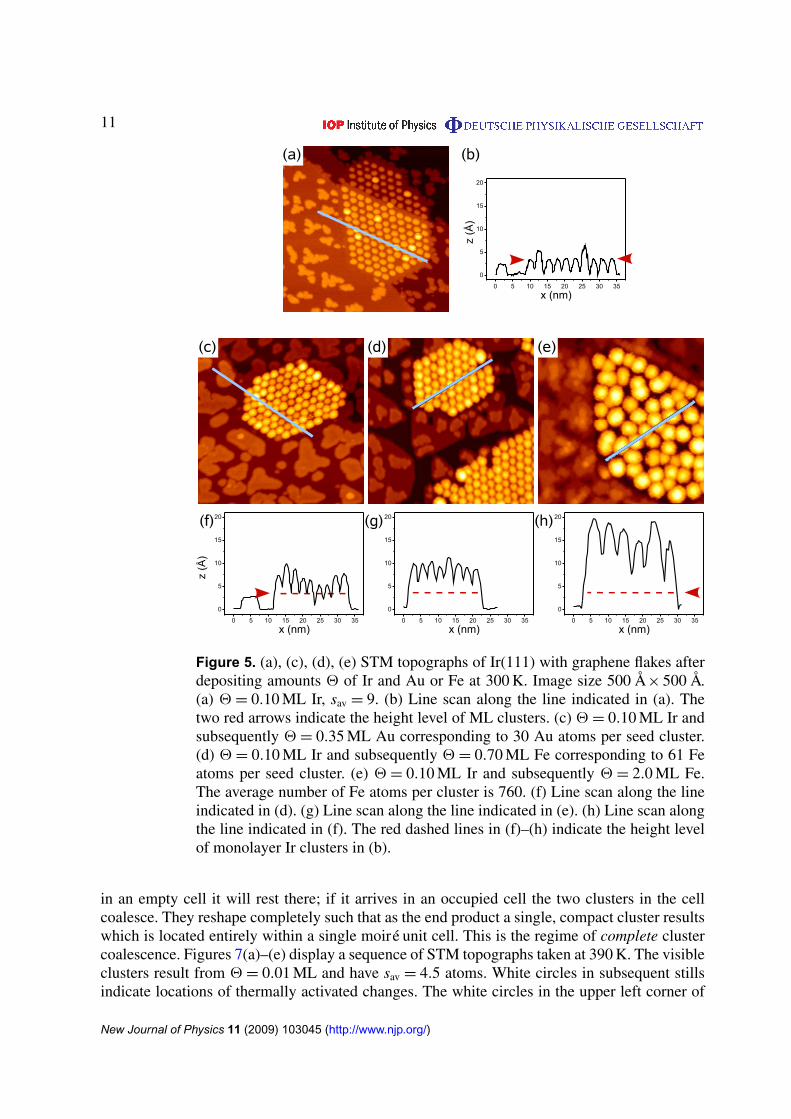
Low cohesive energy metals tend not to form cluster superlattices on the graphene moiré onIr(111), as tested by us for Au, Fe and Ni. Such metals wet high cohesive energy metals, due totheir lower surface-free energy. High cohesive energy metals mostly form rather perfect clustersuperlattices, tested here for Ir, Pt and W. It is thus natural to apply cluster seeding, i.e. to definethe positions of the clusters by a small 2 of a high cohesive energy metal and to grow these seedsby subsequent deposition of a low cohesive energy metal [11, 12]. The successful applicationof this method is visualized in figure 5. As shown in figure 5(a) first through deposition of0.1 ML Ir seed clusters are created in nearly all moiré unit cells. Subsequent deposition of Au(figure 5(b)) or Fe (figure 5(c)) at 300 K results in highly perfect Au and Fe cluster superlatticeswith Ir cores. Comparing figure 1(f) with figure 5(c) for Au and of figure 1(e) with figure 5(d) forFe makes the dramatic effect of seeding obvious. Even after deposition of amounts beyond thecoalescence threshold the seeding has beneficial effects on cluster uniformity and distribution.For deposition of 2 = 2 ML Fe still a high density of large, uniformly sized and spaced Feclusters grows. These Fe clusters contain 760 Fe atoms and have a height of 20 Å (comparefigure 5(h)). They are not more positioned on a superlattice, but span 4–5 moiré unit cells andcontain about 40 Ir atoms.
3.4. Temperature stability
For applications of cluster superlattices in nanomagnetism and nanocatalysis thermal stability ofthe cluster arrays and the absence of sintering at the temperature of use are of crucial importance.To provide data in this respect we investigated the thermal stability of the materials tested so farand display the results in figure 6. The example annealing sequence of figures 6(a)–(f) showsthe gradual decay of the cluster superlattice through isochronal annealing steps of 300 s up to650 K. The Pt cluster superlattice remains intact up to 400 K. Figure 6(g) quantifies annealing byplotting the temperature dependence of the moiré unit cell occupation probability n as a functionof temperature T . It is apparent that the Ir cluster superlattice is indeed the most stable one,decaying as the only one in two steps. Most cluster superlattices are stable up to 400 K, whichprovides a reasonable temperature window for nanocatalysis and nanomagnetism experiments.
The decay of all cluster superlattices occurs due to the thermally activated motion ofclusters. The clusters fluctuate around their equilibrium positions within the moiré unit cell. Themagnitude of cluster fluctuations depends on the cluster size and the internal cluster structure(the isomer). Upon encounter during their fluctuations the clusters merge immediately, on atimescale of less than a second. The outcome of the merging again depends on the cluster size.We distinguish two prototypical situations. (i) The clusters consist only out of a few atoms.Such clusters result from a very low deposited amount 2. For such a 2 also the moiré unit celloccupation probability n is typically well below 1. Through thermally activated fluctuations acluster may surmount the activation barrier Ea to leave its moiré unit cell. If the cluster arrives
New Journal of Physics 11 (2009) 103045 (http://www.njp.org/)
11
Figure 5. (a), (c), (d), (e) STM topographs of Ir(111) with graphene flakes afterdepositing amounts 2 of Ir and Au or Fe at 300 K. Image size 500 Å × 500 Å.(a) 2 = 0.10 ML Ir, sav = 9. (b) Line scan along the line indicated in (a). Thetwo red arrows indicate the height level of ML clusters. (c) 2 = 0.10 ML Ir andsubsequently 2 = 0.35 ML Au corresponding to 30 Au atoms per seed cluster.(d) 2 = 0.10 ML Ir and subsequently 2 = 0.70 ML Fe corresponding to 61 Featoms per seed cluster. (e) 2 = 0.10 ML Ir and subsequently 2 = 2.0 ML Fe.The average number of Fe atoms per cluster is 760. (f) Line scan along the lineindicated in (d). (g) Line scan along the line indicated in (e). (h) Line scan alongthe line indicated in (f). The red dashed lines in (f)–(h) indicate the height levelof monolayer Ir clusters in (b).
in an empty cell it will rest there; if it arrives in an occupied cell the two clusters in the cellcoalesce. They reshape completely such that as the end product a single, compact cluster resultswhich is located entirely within a single moiré unit cell. This is the regime of complete clustercoalescence. Figures 7(a)–(e) display a sequence of STM topographs taken at 390 K. The visibleclusters result from 2 = 0.01 ML and have sav = 4.5 atoms. White circles in subsequent stillsindicate locations of thermally activated changes. The white circles in the upper left corner of
New Journal of Physics 11 (2009) 103045 (http://www.njp.org/)

12
Figure 6. (a)–(f) Annealing sequence of a Pt cluster superlattice on a graphenemoiré on Ir(111) with 2 = 0.25 ML grown at (a) 300 K and subsequentlyannealed in 300 s time intervals to (b) 400 K, (c) 450 K (d) 500 K, (e) 550 Kand (f) 650 K. Image size 700 Å × 700 Å. (g) Occupation probability n of moiréunit cells with clusters as a function of annealing temperature T . (h) Arrheniusplot of cluster hopping rate ν(T ). Lines represent fits for the hopping rate withdiffusion parameters as shown in table 2. For Ir, two parts of dataset (I) and (II)are fitted independently.
figures 7(a)–(c) highlight a situation of thermally activated cluster motion resulting eventuallyin complete cluster coalescence. Note that the resulting cluster appears to be larger and higheras a consequence of complete coalescence. In the Pt annealing sequence of figure 6 in (d) aconsiderable number of larger and higher clusters appear, which are preferentially located nextto empty moiré cells. They are likely to be formed by complete coalescence. In addition, infigures 7(a)–(e) a number of thermally activated cluster jumps into empty cells are circled,
New Journal of Physics 11 (2009) 103045 (http://www.njp.org/)

13
(a)
(f) (g) (h) (i) (j)
(b) (c) (d) (e)
Figure 7. (a)–(e) STM topographs after deposition of 0.01 ML Ir at 350 K andsubsequent heating to 390 K, the time lapse sequence images the same surfacespot every 120 s at 390 K. Image size 250 Å × 250 Å, sav = 4.5 atoms. Circlesindicate where changes take place in successive images. (f)–(j) STM topographsafter deposition of 1.5 ML Ir at 350 K and subsequent heating to 470 K, the timelapse sequence images the same surface spot every 120 s at 470 K. Image size150 Å × 150 Å.
which consequently do not result in cluster coalescence. (ii) If the clusters are large, close tothe coalescence threshold, cluster merging proceeds differently. Still such clusters fluctuatearound the location of their potential energy minimum. According to their large mass andbetter internal stability the magnitude of fluctuations has diminished and one might ask howcluster merging takes place at all. However, only small fluctuations are necessary to initiatecluster merging, as due to their large size the cluster have only a small edge separation of afew Ångströms. For coalescence the clusters do not have to leave their moiré unit cell, butit is sufficient to move a little up their shallow potential energy depression to encounter aneighboring cluster. Due to their size and significant binding the resulting cluster spans twomoiré unit cells and does not reshape completely. This is the regime of cluster sintering orincomplete cluster coalescence. Figures 7(f)–(j) display a situation of cluster sintering imaged at470 K for clusters formed after deposition of 1.5 ML Ir (130 atoms per moiré unit cell) at 350 K.Two subsequent cluster sintering events of neighboring clusters result eventually in a new singlecluster extending over three moiré unit cells. The two scenarios depicted above are extremecases and intermediate situations occur. From what has been said above it appears that clustersuperlattice stability depends also on sav. It is expected that arrays of medium sized clusterswith diminished fluctuation amplitudes and still sufficient separation from their neighbors arethe most stable ones.
To obtain a quantitative estimate for parameters determining cluster superlattice decay wemodel it as follows. We assume the cluster superlattice to consist of clusters with a uniqueactivation energy Ea for cluster interaction with a neighboring cluster and an interactionfrequency ν = ν0e−Ea/kBT , where ν0 is an attempt frequency characterizing the frequency ofcluster fluctuations, kB the Boltzmann constant and T the temperature of the experiment. Theprobability that one cluster encounters another one is proportional to n. We assume completecoalescence, i.e. the final cluster to occupy only a single moiré unit cell. The number of these
New Journal of Physics 11 (2009) 103045 (http://www.njp.org/)

14
Table 2. Diffusion parameters and corresponding statistical errors as derivedfrom ν(T ), for the cases of Ir, Pt and W. The parameters have as well beendetermined separately for two sections (I) and (II) of the dataset as indicatedin figure 6(h). Attempt frequencies have an statistical asymmetric error, so thatnegative and positive ones are given. Systematic errors may be larger (see text).
Clusters Ea (eV) 1Ea (eV) ν0 (Hz) 1ν0,−(Hz) 1ν0,+(Hz)
Ir, 0.45 ML (I) 0.41 0.02 1.4 0.5 0.8Ir, 0.45 ML (II) 0.75 0.2 67 65 2700Ir, 0.45 ML 0.28 0.08 0.06 0.03 0.05Pt, 0.25 ML 0.60 0.08 500 430 3100Pt, 0.70 ML 0.38 0.02 6.2 2.3 3.7W, 0.44 ML 0.47 0.04 33 20 52
events is also proportional to n. Under these conditions the decrease of n with time t at a giventemperature is
dn
dt= −n2ν. (1)
Using integration by parts we solve this differential equation for the boundary of the clusterdensity n1 before, and n2 after an annealing step of a fixed time interval 1t resulting in
ν(T ) =1
1t
(1
n2−
1
n1
). (2)
We emphasize here that our crude approximation effectively averages over different size-dependent interaction frequencies ν for a given size distribution. However, using the annealingtime 1t and the annealing temperature T , this approach allows one to derive the temperaturedependence of ν from an annealing sequence as shown in figures 6(a)–(f).
The resulting Arrhenius plots are shown in figure 7(h). Activation energies are between0.38 and 0.75 eV. The resulting ν0 lie between 1.4 and 500 Hz. These attempt frequencies aremuch lower than a typical phonon frequency and also much lower than what is found for thediffusion of adatoms and small adclusters (compare e.g. [28]). According to transition statetheory the low ν0 point to exceptionally large differences of the partition function of clustersin the bound state versus clusters in the transition state. The diffusion parameters have to beviewed as effective diffusion parameters for an ensemble of clusters comprising all size effectsand not as the properties of an individual cluster. This is also illustrated by the large variationsin parameters for the observed cluster lattices from Pt with different average cluster size.
For the case of Ir as shown in figures 6(g) and (h), there is a distinct discontinuity inthe cluster density and consequently in the estimated interaction frequencies ν between 550and 650 K. Interestingly this transition coincides with all single-layered clusters dying out. Weinterpret the discontinuity as a result of different diffusion parameters for single-layered andmultilayered clusters.
This approach of effective diffusion parameters is checked for consistency with a kineticMonte Carlo simulation. The algorithm for the simulation is based on work by Bortzet al [29]. The cluster lattice is modeled as a hexagonal lattice with clusters, which can hopto adjacent sites with a frequency ν = ν0eEa/kBT based on ν0 and Ea as given in the last fourlines of table 2. The cluster lattice dwells at each annealing temperature for 300 s and is heated
New Journal of Physics 11 (2009) 103045 (http://www.njp.org/)

15
Figure 8. Cluster density n evolution with a Monte Carlo simulation usingaverage diffusion parameters. The temperature is increased every 300 scorresponding to figures 6(g) and (h). Cluster densities after the annealing stepsas in figure 6 are reshown for comparison.
successively to higher temperature annealing intervals. Time for cooling, imaging, and reheatingis omitted. The simulation reproduces the cluster densities well as shown in figure 8. Kinksoccur in the curve where the temperature changes. Not surprisingly, iridium is an exception tothe good match because one kind of clusters dies out rapidly and the approximation of effectivediffusion parameters breaks down for the examined temperature range.
3.5. Binding sites of clusters in the superlattice
Experimentally [17, 20] and by calculations [19] we find Ir clusters to adsorb preferentially inthe hcp regions of the moiré unit cells. These sites differ from the fcc regions only by the factthat instead of a threefold coordinated fcc hollow site, a threefold coordinated hcp hollow siteis centered in the carbon ring. They differ significantly from the atop-type area that has an atopsite centered in the carbon ring. At low growth temperature we find for Ir deposition also fccregions to be populated by small clusters, consistent with the similarity of the two areas [20].It is not at all evident that also other materials adsorb preferentially to hcp regions. Specificallyfor materials with a different crystal structure like W with its bcc structure or Re with the hcpcrystal structure we would not be surprised to find the clusters adsorbed preferentially to fccregions or to be even unspecific to the small difference caused by the second layer underneaththe Ir surface. To obtain cluster-binding sites experimentally we make use of the fact that thegraphene sheets on Ir form a jagged zigzag edge when in contact with a 〈110〉/{100} microfacetor A-step of the substrate. The step undulation of the graphene sheet has the moiré periodicity.The protrusions of the graphene flake’s edge are bowing out towards the Ir terrace at atop-typeareas. This fact does evidently not depend on the deposited material and allows us unambiguouscluster adsorption site assignment. In figure 9 for Ir, Pt, W and Re the corners of the moiré unitcell grids are fixed to these atop-type areas. We find that the clusters are always located in the
New Journal of Physics 11 (2009) 103045 (http://www.njp.org/)

16
Figure 9. Binding site determination for (a) Ir, (b) Pt, (c) W and (d) Re clusters.Deposition was performed at 300 K and (a) 2 = 0.10 ML, sav = 9 atoms;(b) 2 = 0.04 ML, sav = 6 atoms; (c) 2 = 0.04 ML, sav = 4 atoms; (d) 2 =
0.03 ML, sav = 10 atoms. Due to the moiré the graphene flakes form a jaggededge if in contact with a 〈110〉/{100} microfacet or A-step. The dark tips of thejagged graphene edge are atop site areas. Fixing the grid of moiré unit cells tothese positions enables a binding site assignment. The clusters always sit in thegreen triangular half-unit cells pointing away from the step (see text).
triangular half-unit cells pointing away from the one-dimensional graphene–Ir interface (greentriangles in figure 9). According to our unit cell assignment (compare figure 1 of [17]) these arehcp regions.
Let us point out that in figure 8 of [20] and in the accompanying text of section 8 thelabeling and use of the hcp region and the fcc region is erroneously interchanged.
3.6. Toward cluster superlattice materials
To probe the properties of cluster superlattices by averaging techniques and to investigatetheir suitability for potential applications it is necessary to cover a sample macroscopicallywith a cluster superlattice. This need is evident if one considers, e.g. the analysis of reactionproducts from a cluster superlattice in nanocatalysis. The presence of the bare metal wouldresult in additional peaks in thermal desorption spectra and certainly complicate the data
New Journal of Physics 11 (2009) 103045 (http://www.njp.org/)

17
Figure 10. Ir cluster superlattice grown at 300 K with 2 = 0.80 ML resulting insav = 70 on graphene prepared by TPG followed by CVD and extending over theentire sample. Image size 0.5 µm × 0.3 µm, inset 500 Å × 300 Å.
analysis. To establish a macroscopic cluster superlattice the graphene moiré must cover themetal substrate entirely, be of unique orientation with an as large as possible moiré supercellwhich displays upon deposition of suitable materials local rehybridization. While it is likelythat a number of graphene moirés on different metals fulfil all these conditions, so far theyhave been proven only for graphene moirés on Ir(111). Some optimization of the graphenegrowth procedure was necessary to achieve simultaneously full graphene coverage and a singleorientation of the graphene and the graphene moiré [23]–[25]. Figure 10 displays a large-scaleSTM topograph visualizing to a certain extent the quality of the available substrate. The clustersuperlattice is present in the entire topograph in unique orientation and even steps merely presentlocations where a line of clusters is missing, but without disturbing the overall alignment of thesuperlattice.
4. Conclusion
In conclusion, we have established that the graphene moiré on Ir(111) is a versatile andactive template for cluster superlattice growth of a great variety of materials and withmacroscopic lateral extension. If necessary, techniques like low-temperature growth or clusterseeding may permit cluster superlattice growth for cases, where simple room temperaturedeposition fails. The high thermal stability of the cluster superlattices and the ability to growthem on macroscopic areas opens new opportunities for fundamental cluster research andapplications.
New Journal of Physics 11 (2009) 103045 (http://www.njp.org/)

18
Acknowledgments
Work at Cologne University was supported by DFG through the project ‘Two DimensionalCluster Lattices on Graphene Moirés’. TM acknowledges useful discussion with Peter JFeibelman.
Note added in proof. During the preparation of this manuscript, the fabrication of regular clusterlattices of Pt on graphene on the graphene/Ru(0001) moiré was demonstrated; see [30].
References
[1] Khanna S N and Castleman A W (ed) 2003 Quantum Phenomena in Clusters and Nanostructures (Berlin:Springer)
[2] Haberland H, Kleinermanns K and Träger F 2005 Gase, Flüssigkeiten, Nanosysteme, Chapter: Cluster 2ndedn (Bergmann/Schäfer vol 5) (Berlin: de Gruyter)
[3] Kreibig U and Vollmer M (ed) 1995 Optical Properties of Metal Clusters (Berlin: Springer)[4] Heiz U and Landmann U (ed) 2006 Nanocatalysis (Berlin: Springer)[5] Meiwes-Broer K-H (ed) 2000 Metal Clusters at Surfaces (Berlin: Springer)[6] Becker C and Wandelt K 2008 Two-dimensional Templates (Topics in Current Chemistry vol 287) (Berlin:
Springer)[7] Repain V, Baudot G, Ellmer H and Rousset S 2002 Two-dimensional long-range-ordered growth of uniform
cobalt nanostructures on a Au(111) vicinal template Europhys. Lett. 58 730[8] Weiss N et al 2005 Uniform magnetic properties for an ultrahigh-density lattice of noninteracting co
nanostructures Phys. Rev. Lett. 95 157204[9] Rohart S, Girard Y, Nahas Y, Repain V, Rodary G, Tejeda A and Rousset S. Growth of iron on gold (788)
vicinal surface: from nanodots to step flow Surf. Sci. 602 28[10] Degen S, Becker C and Wandelt K 2004 Bimetallic Pd–Au nanocluster arrays grown on nanostructured
alumina templates Faraday Discuss. 125 343[11] Schmid M, Kresse G, Buchsbaum A, Napetschnig E, Gritschneder S, Reichling M and Varga P 2007
Nanotemplate with holes: ultrathin alumina on Ni3Al(111) Phys. Rev. Lett. 99 196104[12] Hamm G, Becker C and Henry C R 2006 Bimetallic Pd–Au nanocluster arrays grown on nanostructured
alumina templates Nanotechnology 170 1943[13] Lehnert A, Krupski A, Degen S, Franke K, Decker R, Rusponi S, Kralj M, Becker C, Brune H and
Wandelt K 2006 Nucleation of ordered Fe islands on Al2O3/Ni3Al(111) Surf. Sci. 600 1804[14] Zhang J, Sessi V, Michaelis C H, Brihuega I, Honolka J, Kern K, Skomski R, Chen X, Rojas G and
Enderse A 2008 Ordered layers of Co clusters on BN template layers Phys. Rev. B 78 165430[15] Varykhalov A, Rader O and Gudat W 2008 Origin of Au nanostructures on tungsten surface carbides Phys.
Rev. B 77 035412[16] Bachmann M, Gabl M, Deisl C, Memmel N and Bertel E 2009 Quasi-one-dimensional self-assembly of metal
nanoclusters on C/W(110) Phys. Rev. B 78 235410[17] N’Diaye A T, Bleikamp S, Feibelman P J and Michely T 2006 Two-dimensional Ir cluster lattices on a
graphene moiré on Ir(111) Phys. Rev. Lett. 97 215501[18] Pletikosic I, Kralj M, Brako R, Coraux J, N’Diaye A T, Busse C and Michely T 2009 Dirac cones and
minigaps for graphene on Ir(111) Phys. Rev. Lett. 102 056808[19] Feibelman P J 2008 Pinning of graphene to Ir(111) by flat Ir dots. Phys. Rev. B 77 165419[20] N’Diaye A T, Coraux J, Plasa T N, Busse C and Michely T 2008 Structure of epitaxial graphene on Ir(111)
New J. Phys. 10 043033[21] Aktrük O Ü and Tomak M 2009 AunPtn clusters adsorbed on graphene studied by first-principles calculations
Phys. Rev. B 80 085417
New Journal of Physics 11 (2009) 103045 (http://www.njp.org/)
19
[22] Mao Y, Yuan J and Zhong J 2008 Density functional calculation of transition metal adatom adsorption ongraphene J. Phys.: Condens. Matter 20 1152029
[23] Coraux J, N’Diaye A T, Engler M, Busse C, Wall D, Buckanie N, Meyer zu Heringdorf F-J, van Gastel R,Poelsema B and Michely T 2009 Growth of graphene on Ir(111) New J. Phys. 11 023006
[24] Coraux J, N’Diaye A T, Busse C and Michely T 2008 Structural coherency of graphene on Ir(111) Nano Lett.8 565–70
[25] van Gastel R, N’Diaye A T, Wall D, Coraux J, Busse C, Meyer zu Heringdorf F-J, Buckanie N, von HoegenM H, Michely T and Poelsema B 2009 Selecting a single orientation for millimeter sized graphene sheetsAppl. Phys. Lett. 95 121901
[26] Loginova E, Nie S, Thurmer K, Bartelt N C and McCarty K F 2009 Defects of graphene on Ir(111): Rotationaldomains and ridges Phys. Rev. B 80 085430
[27] Bardotti L, Jensen P, Hoareau A, Treilleux M and Cabaud B 1995 Experimental observation of fast diffusionof large Antimony cluster on graphite surfaces Phys. Rev. Lett. 74 4694
[28] Wang S C and Ehrlich G 1990 Structure, stability and surface diffusion of clusters:Irx on Ir(111) Surf. Sci.239 301–32
[29] Bortz A B, Kalos M H and Lebowitz J L 1975 New algorithm for Monte-Carlo simulation of Ising spinsystems J. Comput. Phys. 17 10–8
[30] Donner K and Jakob P 2009 Structural properties and site-specific interactions of Pt with thegraphene/Ru(0001) moiré overlayer J. Phys. Chem. in press
New Journal of Physics 11 (2009) 103045 (http://www.njp.org/)
![Download [3.72 MB]](https://static.fdocuments.net/doc/165x107/587892181a28aba5258b53fe/download-372-mb.jpg)