
PDF (1.37 MB) - IOPscience
11
Journal of Instrumentation FTK: a Fast Track Trigger for ATLAS To cite this article: J Anderson et al 2012 JINST 7 C10002 View the article online for updates and enhancements. You may also like Upper limits on the strength of periodic gravitational waves from PSR J1939+2134 B Allen, G Woan, (for the LIGO Scientific Collaboration) et al. - Experimental study of different silicon sensor options for the upgrade of the CMS Outer Tracker W. Adam, T. Bergauer, D. Blöch et al. - The CMS Phase-1 pixel detector upgrade W. Adam, T. Bergauer, D. Blöch et al. - Recent citations Field Programmable Gate Array Applications—A Scientometric Review Juan Ruiz-Rosero et al - Study of the retina algorithm on FPGA for fast tracking Zi-Xuan Song et al - Firmware development and testing of the ATLAS IBL Back Of Crate card M.E. Stramaglia - This content was downloaded from IP address 102.66.91.204 on 13/12/2021 at 08:12
Transcript of PDF (1.37 MB) - IOPscience
Journal of Instrumentation
FTK a Fast Track Trigger for ATLASTo cite this article J Anderson et al 2012 JINST 7 C10002
View the article online for updates and enhancements
You may also likeUpper limits on the strength of periodicgravitational waves from PSR J1939+2134B Allen G Woan (for the LIGO ScientificCollaboration) et al
-
Experimental study of different siliconsensor options for the upgrade of the CMSOuter TrackerW Adam T Bergauer D Bloumlch et al
-
The CMS Phase-1 pixel detector upgradeW Adam T Bergauer D Bloumlch et al
-
Recent citationsField Programmable Gate ArrayApplicationsmdashA Scientometric ReviewJuan Ruiz-Rosero et al
-
Study of the retina algorithm on FPGA forfast trackingZi-Xuan Song et al
-
Firmware development and testing of theATLAS IBL Back Of Crate cardME Stramaglia
-
This content was downloaded from IP address 1026691204 on 13122021 at 0812
2012 JINST 7 C10002
PUBLISHED BY IOP PUBLISHING FOR SISSA MEDIALAB
RECEIVED June 14 2012ACCEPTED August 22 2012
PUBLISHED October 10 2012
WIT2012 mdash WORKSHOP ON INTELLIGENT TRACKERS3ndash5 MAY 2012INFN PISA ITALY
FTK a Fast Track Trigger for ATLAS
J Anderson f A Andreanimn A Andreazzamn A Annovib M Atkinsone
B Auerbach f M Berettab V Bevacquaac R Blair f G Blazeyq M Bogdand
A Boveiad F Canellid j A Castegnarob V Cavalieree F Cervignir P Change
Y Chengd M Citteriom F Crescioliac M DellrsquoOrsoac G Drake f M Dunfordd
L Fabbriop A Favaretomn M Franchiniop S Geer j P Giannettia F Giannuzziop
F Giorgio S Gruenendahl j H-L Lid J Hoff j T Iizawah O Jamieson j A Kapliyd
M Kastene YK Kimd j N Kimurah A Lanzak F Lasagniop V Liberalimn T Liu j
D Magalottibr A McCarne C Melachrinosd C Meronim T Mitanih P Murat j
A Negrilk M Neubauere Y Okumurad j B Penningd j1 M Piendibeneac
J Proudfoot f C Rodaac I Saccot Y Sakuraih C Sbarrao M Shochetd
A Stabilemn J Tangd F Tangd L Tompkinsd R Tripiccioneg J Tuggled
S Valentinettiop V Vercesik M Verzocchi j M Villaop G Volpibd J Websterd
K Yoritah J Zhang f and A Zoccoliop
aSezione di Pisa INFN Pisa ItalybLaboratori Nazionali INFN Frascati ItalycDepartment of Physics University of Pisa Pisa ItalydDepartment of Physics and Enrico Fermi Institute University of Chicago Chicago Illinois USAeDepartment of Physics University of Illinois at Urbana-Champaign Urbana Illinois USAf Argonne National Laboratory Argonne Illinois USAgDepartment of Physics University of Ferrara Ferrara ItalyhDepartment of Physics Waseda University Waseda JapaniDepartment of Physics University of Harward Harvard Massachusetts USAjFermi National Accelerator Laboratory Fermilab Batavia Illinois USAkSezione di Pavia INFN Pavia ItalylDepartment of Physics University of Pavia Pavia Italy
mSezione di Milano INFN Milan ItalynDepartment of Physics University of Milan Milan Italy
1Corresponding author
ccopy 2012 IOP Publishing Ltd and Sissa Medialab srl doi1010881748-0221710C10002
2012 JINST 7 C10002
oSezione di Bologna INFN Bologna ItalypDepartment of Physics University of Bologna Bologna ItalyqNorthern Illinois University DeKalb Illinois USArDepartment of Physics University of Perugia Perugia ItalysUniversity of Copenhagen Copenhagen Denmarkt Institute of Computer Engineering University of Heidelberg Heidelberg Germany
E-mail penningcernch
ABSTRACT We describe the design and expected performance of a the Fast Tracker Trigger (FTK)system for the ATLAS detector at the Large Hadron Collider The FTK is a highly parallel hardwaresystem designed to operate at the Level 1 trigger output rate It is designed to provide global tracksreconstructed in the inner detector with resolution comparable to the full offline reconstruction asinput of the Level 2 trigger processing The hardware system is based on associative memories forpattern recognition and fast FPGAs for track reconstruction The FTK is expected to dramaticallyimprove the performance of track based isolation and b-tagging with little to no dependencies ofpile-up interactions
KEYWORDS Trigger concepts and systems (hardware and software) Trigger algorithms
2012 JINST 7 C10002
Contents
1 The FTK system 111 The ATLAS detector and trigger 1
2 Technical design 221 Overview 222 Pattern recognition and track fitting 323 Variable resolution patterns 4
3 Physics with the FTK 431 Simulated performance 5
4 Conclusion 5
1 The FTK system
The FTK [1] is a trigger upgrade for the ATLAS detector at the Large Hadron Collider (LHC)As the LHC luminosity approaches its design luminosity of 1034cm2s the combinatorial prob-lem arising from charged particle tracking becomes increasingly difficult resulting in lower signalefficiencies for constant fake rates for larger pile-up The FTK is a highly-parallel hardware sys-tem intended to provide high-quality reconstruction of all tracks with transverse momentum above1 GeV Its speed and physics performance have been estimated at simulated luminosities up to3times1034cm2s corresponding to 75 interactions per bunch crossing at a bunch crossing interval of25 ns An overview of the ATLAS detector and trigger system is given in the following sectionfollowed by details of pattern recognition track fitting and physics performance
11 The ATLAS detector and trigger
ATLAS is one of the two general-purpose detectors at the LHC [2] It is designed to detect parti-cles produced in proton-proton collisions at a center of mass energy of
radics = 14 TeV Particles are
detected (moving from the interaction point) by the inner tracking system followed by the electro-magnetic and the hadronic calorimeters and at the end by the muon system ATLAS collected inthe years 2010minus2011 53 fbminus1 of data with an energy of
radics = 7 TeV Peak luminosities of about
35times1033cms have been achieved In 2012 the LHC energy is increased toradic
s = 8 TeV with peakluminosities exceeding 6times1033cms The inner detector consists of the Pixel detector the Semi-conductor Tracker (SCT) and the Transition Radiation Tracker (TRT) The inner tracker is inside a2 T solenoidal magnetic field The Pixel detector system contains 80 M channels of 50x400 microm2
silicon pixels These are arranged in three cylindrical layers with radii of 5 9 and 12 cm with threedisks on each side located at distances of 495580 and 650mm in z and covering a radial region of9 and 15 cm Typically each track traverses three Pixel layers up to |η |lt 24 The ATLAS detector
ndash 1 ndash
2012 JINST 7 C10002
will be upgraded by installation of an additional Pixel Detector layer The new layer will be in-serted between the B-layer of the existing pixel detector and a new smaller radius beam-pipe TheSCT system consists of 4 double layer of silicon strip detectors Each double layer has an axial-and a stereo layer with 80 microm pitch oriented along the beam direction (axial) in one layer andtilted by 40 mrad angle (stereo) in the second one The entire SCT has 6M channels and consistsof cylinders at radii of 300 373 447 and 520 cm The end-cap modules are very similar inconstruction but use tapered strips aligned radially The FTK uses all 3 Pixel and 4 SCT doublelayers mapped into 11 logical layers Use of the insertable B-layer is anticipated too The rapiditycoverage extends up to |η |lt 25 Details regarding the inner detector are given in ref [2]
A three level trigger system [3] is used to select interesting events The first level is hardware-based operating at a maximum output rate of 100 kHz It provides regions of interest portionsof the detector in azimuth and pseudorapidity which causes the event to trigger Level 2 and theEvent Filter are build by using computing farms and are collectively known as the High Level Trig-ger (HLT) The HLT consists of several thousand CPUs Level 2 operates within regions of interestwith an output rate of 2 kHz while the Event Filter has access to all information in the event withan output rate of 200 Hz
2 Technical design
21 Overview
The FTK system core design is based on the experience of the Silicon Vertex Trigger at the CDF de-tector at Fermilab [7 8] The system is based on FPGAs and a highly-parallel Associative Memory(AM) chip [9] The system is divided into eight core crates each covering a 45 range in azimuthplus 10 overlap Each core crate is further divided into four regions of η and two regions in φ Thisyields 8 ηminusφ towers per crate and 64 trigger towers altogether A ηminusφ tower is served by two pro-cessing units containing the AM chips for pattern recognition Track Fitters (TF) Data Organizers(DO) to coordinate between pattern recognition and track fitting and a Hit Warrior (HW) to removeduplicate tracks from the output The processing units receive inputs from Data Formatter (DF)boards and pass their output to second stage boards which perform final full resolution track fittingand quality tests Each of these components are described below A sketch is given in figure 1
Dual output front end links (RODs in figure 1) from the silicon detectors direct a duplicate setof the output to the Data Formatter boards which perform hit clustering and formatting of the datato be mapped to the 11 logical layers of the FTK architecture Then it routes the clusters to therelevant processing units In each processing unit the Data Organizer reduces the cluster resolutionby a factor asymp 10 into superstrips used for pattern recognition while storing the full resolution clus-ters for track fitting The superstrips then are passed to the AM chips Those operate in parallelto compare the incoming superstrips to approximately 100 million precomputed patterns per corecrate Matched patterns are sent back to the DO which retrieves the full resolution hits and sendsthem to the Track Fitter The TF does linear calculations of the helix parameters and χ2 compo-nents using prestored constants and the location of the hit in each layer Every combination of hitswithin a given pattern is fitted those passing a fit-quality criteria are kept The last stage of eachprocessing unit is the Hit Warrior which removes duplicate tracks based on the number of sharedhits between various tracks and the χ2 of the fit
ndash 2 ndash
2012 JINST 7 C10002
Figure 1 Sketch of the FTK system [1]
22 Pattern recognition and track fitting
FTK tracking is performed in two stages to keep the combinatorics at a manageable level The firststage uses 8 out of 11 silicon layers for pattern recognition and track fitting while the second stagerefits the tracks found in the first stage using all 11 layers The first 8 layer stage uses 3 Pixel 4axial SCT and 1 stereo SCT layer At least seven of eight layers are required to have a hit Thepattern matching takes places in CAM-based custom built AM chips each containing 50k-100kpatterns each Hits entering the system are simultaneously compared to all stored patterns TheAM chips are grouped in sets of 32 chips on a local associative memory board (LAMB) EachAM board contains four LAMBs Once all matched patterns called roads in an event are foundthe information is sent back to the DO The DOs are located on an auxiliary (AUX) card attachedto the AM board Each AUX card has four instances of the Data Organizer Track Fitter and HitWarrior Upon receiving the roads from a LAMB the Data Organizer looks up the full resolutionhits within a road and sends them to the Track Fitter The TF unit is expected to fit one track pernanosecond This high rate is achieved by the large numbers of DSPs in the FPGA used to performa simple linear fit for each set of N hit coordinates x j
pi =N
sumj
ci jx j +qi (21)
The pi are the five helix parameters and the Nminus5 χ2 components all of which are determinedfrom the constants ci j and q j If a fit is above a given χ2 threshold and the candidate track hashits in all the detector layers a majority recovery is performed During this recovery the track isrefitted several times ignoring one of the hits each time to check whether a subset of hits will yielda good χ2 This allows a track to be recovered if one of the hits in the combination comes fromnoise or from a different track The second stage of fitting uses the good tracks from the first stageto look for expected hits in the remaining 3 layers using an inversion of eq (21) If at least 10 outof 11 hits are found the track is refit with all of the hits and subjected to a final fit quality test Thetracking process takes in average about 15 microsec
ndash 3 ndash
2012 JINST 7 C10002
23 Variable resolution patterns
One of the challenges in the design of the FTK is the large number of matched roads expected at3times1034cm2s Although the system is already segmented into independently operating ηminusφ tow-ers the number of matched roads out of the AM could still be a challenge for the Data Organizer atvery high instant luminosities and better pattern matching resolution could be necessary Variable-resolution patterns have been developed to obtain better resolutions with equal AM bank sizes orthe same resolution with much smaller banks [10] Finer-resolution patterns lead to a lower fakerate at the cost of more required AM space while coarse resolution maintains higher efficiencyat the cost of increased combinatorics in the Track Fitter The solution described here maintainsa balance between these considerations The logic of the AM chip design has been upgraded toinclude local subdivisions of each superstrip in a pattern
The ldquodonrsquot carerdquo feature of modern CAMs is implemented so that the width of each patterncan be varied layer by layer This allows the available hardware pattern space to be optimized tomaximize efficiency while minimizing the number of random hits that have to be fit
Simulation studying events with different pile-up conditions have been performed A standardAM bank produces roughly the same number of roads of a variable resolution pattern bank that is3ndash5 times smaller when using a single DC bit in the AM logic [10] At the level of 70 pile-up afairly uniform 900ndash1300 clusters are expected per layer and tower
3 Physics with the FTK
There is a variety of physics applications for the FTK One of the most prominent is the source ofelectroweak symmetry breaking which remains yet unknown The easiest explanation the Higgsmechanism [4ndash6] predicts the Higgs boson whose branching ratios to other particles are dependenton the their masses Therefore the production of heavy particles like b-quarks and τ leptons areof particular interest These couplings can be modified by new physics and their measurementis a crucial test for the Standard Model We will show that particuarly for these final states theFTK system leads to significant improvements In Standard Model measurements the FTK helpsto maintain high efficiencies while controlling background processes at high pile-up
Figure 2 left shows the isolated muon efficiency using the EM calorimeter isolation withtwo different cell energy thresholds as function of the number of pile-up interactions The selec-tion criteria are chosen such that the bb rejection factor is 10 The second plot of the same figuredemonstrates that by applying tracking isolation in contrast to calorimeter isolation the efficiencyimproves Considering only tracks from the muon vertex by applying a selection criteria on thedistance between muon and track at the beamline track the efficiency becomes largely independentof the pile-up These examples demonstrate that tracking can play an important role in identifica-tion of interesting events while maintaining high efficiency With increasing luminosity the use oftracking increases even more The FTK will operate at the Level 1 trigger output rate reconstruct-ing all tracks at near-offline quality for use in the HLT In addition this frees up CPU time in theHLT which can be used for other purposes
ndash 4 ndash
2012 JINST 7 C10002
Pythia Wrarrμν with 2middotnoise cut
0 5 10 15 20 25 30 35 40
0
02
04
06
08
1
12
EM isolation onlybb rejection = 100
Pythia Wrarrμν
1034 pile-up
NUMBER OF PILE-UP INTERACTIONS
SIG
NA
L E
FF
ICIE
NC
Y
0 5 10 15 20 25 30 35 40
0
02
04
06
08
1
12
Pythia WrarrμνPythia Wrarrμν with z0 cut
Tracking isolation onlybb rejection = 100
1034 pile-up
NUMBER OF PILE-UP INTERACTIONS
SIG
NA
L E
FF
ICIE
NC
YFigure 2 Left Isolated muon efficiency using the EM calorimeter isolation with two different cell energythresholds as a function of the number of pile-up interactions for a fixed bb rejection factor of 10 RightIsolated muon efficiency using track isolation with and without a cut on the distance between the track andthe muon at the beamline as a function of the number of pile-up interactions for a fixed bb rejection factorof 10 Signal efficiency here gives the efficiency to select isolated muons Figures from [1]
31 Simulated performance
The FTK system has been simulated in software to determine its expected performance [1] Tracksprovided by the FTK system are compared with tracks reconstructed using the ATLAS offlinetracking algorithm The resolution of track parameters is shown in figure 3 for tracks with |η |lt 1demonstrating that the FTK resolution is comparable to that of the offline tracking
The FTK configuration uses collections of pre-calculated pattern (pattern banks) and linearizedfitting constants suitable for up to 75 pile-up interactions Figure 4 shows the efficiency of the FTKand offline algorithm to reconstruct muons of pT gt 1 GeV The efficiency drops for FTK tracksaround pseudorapidity η = 1 are located at the transition region between barrel detector and for-ward disks These have been addressed by relaxing the number of hits required in these particularregions
The potential for heavy flavor identification (b-tagging) with the FTK tracks at high luminosi-ties is evaluated using an algorithm based on the transverse impact parameter d0 of tracks in jetsTemplate histograms of the impact parameter divided by its uncertainty are created for light jets andb jets These are combined to form a likelihood Figure 5 shows the expected b-quark efficiencyalong with typical light jet rejection factor for FTK and offline tracks Simulated event samples areWHrarr bb Typical b-tagging efficiencies used in analyses are sim 05ndash07
4 Conclusion
The Fast Track Trigger for ATLAS will be able to increase efficiency and control background pro-cesses for particularly interesting events containing b quarks τ leptons and isolated high pT elec-trons and muons This is achieved by using global high speed tracking at the beginning of the
ndash 5 ndash
2012 JINST 7 C10002
RECO - TRUTH CURVATURE (1GeV)00 02 04-02-04E
NT
RIE
S
BIN
000
002
004
006
008OFFLINEFTK
RECO d0 - TRUTH d0 (cm)0
001
002
003
004
0001 002002 001
OFFLINEFTK
EN
TR
IES
B
IN
EN
TR
IES
B
IN
RECO η - TRUTH η0 002 004-004 -002
0
01
02OFFLINEFTK
OFFLINEFTK
EN
TR
IES
B
IN
RECO φ0 - TRUTH φ0 (rad)
002
004
00 0004-0004 0008-0008
OFFLINEFTK
RECO z0 - TRUTH z0 (cm)
EN
TR
IES
B
IN
0
002
004
006
0-004 004 008-008
Figure 3 Comparison of the helix parameters for Offline track reconstruction (black) and FTK (red) Thetrackrsquos transverse momentum is required to exceed 1 GeV and its pseudorapidity is limited to the centralregion (|η |lt 1) A single muon sample is used Figure from [1]
TRUTH pT (GeV)2 4 6 8 10 12 14 16 18 20 22 24
EF
FIC
IEN
CY
0
01
02
03
04
05
06
07
08
09
10
OFFLINEFTK
-2 -15 -1 -05 0 05 1 15 252
EF
FIC
IEN
CY
0
01
02
03
04
05
06
07
08
09
10
TRUTH η
OFFLINEFTK
Figure 4 Comparison between single muon tracking efficiencies for FTK and offline algorithms vs pT
(left) and η (right) Figures from [1]
Level 2 trigger The challenges given by increased combinatorics in track reconstruction with in-creasing luminosity and simultaneously greater need for computational power are solved by usingprecomputed AM based patterns and fast FPGAs in a highly parallel system
A vertical slice test using collision data in summer 2012 is in preparation [11] The dual out-put silicon detector front end cards needed are already installed in ATLAS The full set of dualoutput cards for the final system is already produced A data formatter prototype board is currentlyunder design and will be ready by summer 2012 A prototype input mezzazine [12] is ready for
ndash 6 ndash
2012 JINST 7 C10002
04 05 06 07 08 09 1
LIG
HT
QU
AR
K R
EJE
CT
ION
B TAGGING EFFICIENCY
1
10
210
SIGNED D0 SIGNIFICANCE LIKELIHOODTAGGING PERFORMANCE
3 1034 PILEUPOFFLINEFTK 11L
Figure 5 Light-quark jet rejection vs b-quark jet efficiency for offline and FTK tracks at pile-up as expectedfor a luminosity of asymp 3times 1034 The FTK simulation uses as configuration of 11 layer (11L) Figure fromref [1]
the vertical slice test The AM chip prototype (AMchip04) is expected by early summer 2012 andthe design of the AM board (AMBFTK) is finished An existing board (AMBslim5) [13] will beused for the vertical slice test For the data organizer board a pre-prototype is available and will beused in high-speed testing The second stage board which performs the full 11 layer fit is currentlyundergoing conceptual design and firmware development We expect the system to be operationalin the data taking period following the 2013-2014 shutdown
Acknowledgments
The author thanks the organizers of the WIT2012 workshop for the invitation the FTK collabora-tion and TDAQ speakers committee for their advise preparing the presentation and these proceed-ings The Fast Tracker project receives support from Istituto Nazionale di Fisica Nucleare fromthe US Department of Energy and National Science Foundation from Grant-in-Aid for ScientificResearch by Japan Society for the Promotion of Science from European community FP7 (MarieCurie OIF Project 254410 - ARTLHCFE)
References
[1] A Andreani et al The fast tracker real time processor and its impact on muon isolation tau andb-jet online selections at ATLAS IEEE Trans Nucl Sci 59 (2012) 348
[2] ATLAS collaboration G Aad et al The ATLAS experiment at the CERN Large Hadron Collider2008 JINST 3 S08003
[3] ATLAS collaboration G Aad et al Expected performance of the ATLAS experiment mdash detectortrigger and physics arXiv09010512
[4] F Englert and R Brout Broken symmetry and the mass of gauge vector mesons Phys Rev Lett 13(1964) 321
[5] PW Higgs Broken symmetries and the masses of gauge bosons Phys Rev Lett 13 (1964) 508
ndash 7 ndash
2012 JINST 7 C10002
[6] G Guralnik C Hagen and T Kibble Global conservation laws and massless particles Phys RevLett 13 (1964) 585
[7] J Adelman et al The silicon vertex trigger upgrade at CDF Nucl Instrum Meth A 572 (2007) 361
[8] A Annovi et al A VLSI processor for fast track finding based on content addressable memoriesIEEE Trans Nucl Sci 53 (2006) 2428
[9] M DellrsquoOrso and L Ristori VLSI structures for track finding Nucl Instrum Meth A 278 (1989)436
[10] A Annovi et al A new variable-resolution associative memory for high energy physicsAdvancements in Nuclear Instrumentation Measurement Methods and their Applications (ANIMMA)2011 2nd International Conference on Digital Object Identifier ANIMMA (2011)
[11] A Annovi et al The EDRO board connected to the associative memory ldquobabyrdquo fasttrackerprocessor for the ATLAS experiment in 2nd International Conference on Technology andInstrumentation in Particle Physics Chicago IL USA 9ndash14 June 2011
[12] A Annovi and M Beretta A fast general-purpose clustering algorithm based on FPGAs forhigh-throughput data processing Nucl Instrum Meth A 617 (2010) 254 [arXiv09102572]
[13] A Annovi et al Associative memory design for the Fast Tracker Processor (FTK) at ATLAS IEEENucl Sci Symp Med Imag Conf (NSSMIC) (2011) 141
ndash 8 ndash
- The FTK system
-
- The ATLAS detector and trigger
-
- Technical design
-
- Overview
- Pattern recognition and track fitting
- Variable resolution patterns
-
- Physics with the FTK
-
- Simulated performance
-
- Conclusion
-
2012 JINST 7 C10002
Contents
1 The FTK system 111 The ATLAS detector and trigger 1
2 Technical design 221 Overview 222 Pattern recognition and track fitting 323 Variable resolution patterns 4
3 Physics with the FTK 431 Simulated performance 5
4 Conclusion 5
1 The FTK system
The FTK [1] is a trigger upgrade for the ATLAS detector at the Large Hadron Collider (LHC)As the LHC luminosity approaches its design luminosity of 1034cm2s the combinatorial prob-lem arising from charged particle tracking becomes increasingly difficult resulting in lower signalefficiencies for constant fake rates for larger pile-up The FTK is a highly-parallel hardware sys-tem intended to provide high-quality reconstruction of all tracks with transverse momentum above1 GeV Its speed and physics performance have been estimated at simulated luminosities up to3times1034cm2s corresponding to 75 interactions per bunch crossing at a bunch crossing interval of25 ns An overview of the ATLAS detector and trigger system is given in the following sectionfollowed by details of pattern recognition track fitting and physics performance
11 The ATLAS detector and trigger
ATLAS is one of the two general-purpose detectors at the LHC [2] It is designed to detect parti-cles produced in proton-proton collisions at a center of mass energy of
radics = 14 TeV Particles are
detected (moving from the interaction point) by the inner tracking system followed by the electro-magnetic and the hadronic calorimeters and at the end by the muon system ATLAS collected inthe years 2010minus2011 53 fbminus1 of data with an energy of
radics = 7 TeV Peak luminosities of about
35times1033cms have been achieved In 2012 the LHC energy is increased toradic
s = 8 TeV with peakluminosities exceeding 6times1033cms The inner detector consists of the Pixel detector the Semi-conductor Tracker (SCT) and the Transition Radiation Tracker (TRT) The inner tracker is inside a2 T solenoidal magnetic field The Pixel detector system contains 80 M channels of 50x400 microm2
silicon pixels These are arranged in three cylindrical layers with radii of 5 9 and 12 cm with threedisks on each side located at distances of 495580 and 650mm in z and covering a radial region of9 and 15 cm Typically each track traverses three Pixel layers up to |η |lt 24 The ATLAS detector
ndash 1 ndash
2012 JINST 7 C10002
will be upgraded by installation of an additional Pixel Detector layer The new layer will be in-serted between the B-layer of the existing pixel detector and a new smaller radius beam-pipe TheSCT system consists of 4 double layer of silicon strip detectors Each double layer has an axial-and a stereo layer with 80 microm pitch oriented along the beam direction (axial) in one layer andtilted by 40 mrad angle (stereo) in the second one The entire SCT has 6M channels and consistsof cylinders at radii of 300 373 447 and 520 cm The end-cap modules are very similar inconstruction but use tapered strips aligned radially The FTK uses all 3 Pixel and 4 SCT doublelayers mapped into 11 logical layers Use of the insertable B-layer is anticipated too The rapiditycoverage extends up to |η |lt 25 Details regarding the inner detector are given in ref [2]
A three level trigger system [3] is used to select interesting events The first level is hardware-based operating at a maximum output rate of 100 kHz It provides regions of interest portionsof the detector in azimuth and pseudorapidity which causes the event to trigger Level 2 and theEvent Filter are build by using computing farms and are collectively known as the High Level Trig-ger (HLT) The HLT consists of several thousand CPUs Level 2 operates within regions of interestwith an output rate of 2 kHz while the Event Filter has access to all information in the event withan output rate of 200 Hz
2 Technical design
21 Overview
The FTK system core design is based on the experience of the Silicon Vertex Trigger at the CDF de-tector at Fermilab [7 8] The system is based on FPGAs and a highly-parallel Associative Memory(AM) chip [9] The system is divided into eight core crates each covering a 45 range in azimuthplus 10 overlap Each core crate is further divided into four regions of η and two regions in φ Thisyields 8 ηminusφ towers per crate and 64 trigger towers altogether A ηminusφ tower is served by two pro-cessing units containing the AM chips for pattern recognition Track Fitters (TF) Data Organizers(DO) to coordinate between pattern recognition and track fitting and a Hit Warrior (HW) to removeduplicate tracks from the output The processing units receive inputs from Data Formatter (DF)boards and pass their output to second stage boards which perform final full resolution track fittingand quality tests Each of these components are described below A sketch is given in figure 1
Dual output front end links (RODs in figure 1) from the silicon detectors direct a duplicate setof the output to the Data Formatter boards which perform hit clustering and formatting of the datato be mapped to the 11 logical layers of the FTK architecture Then it routes the clusters to therelevant processing units In each processing unit the Data Organizer reduces the cluster resolutionby a factor asymp 10 into superstrips used for pattern recognition while storing the full resolution clus-ters for track fitting The superstrips then are passed to the AM chips Those operate in parallelto compare the incoming superstrips to approximately 100 million precomputed patterns per corecrate Matched patterns are sent back to the DO which retrieves the full resolution hits and sendsthem to the Track Fitter The TF does linear calculations of the helix parameters and χ2 compo-nents using prestored constants and the location of the hit in each layer Every combination of hitswithin a given pattern is fitted those passing a fit-quality criteria are kept The last stage of eachprocessing unit is the Hit Warrior which removes duplicate tracks based on the number of sharedhits between various tracks and the χ2 of the fit
ndash 2 ndash
2012 JINST 7 C10002
Figure 1 Sketch of the FTK system [1]
22 Pattern recognition and track fitting
FTK tracking is performed in two stages to keep the combinatorics at a manageable level The firststage uses 8 out of 11 silicon layers for pattern recognition and track fitting while the second stagerefits the tracks found in the first stage using all 11 layers The first 8 layer stage uses 3 Pixel 4axial SCT and 1 stereo SCT layer At least seven of eight layers are required to have a hit Thepattern matching takes places in CAM-based custom built AM chips each containing 50k-100kpatterns each Hits entering the system are simultaneously compared to all stored patterns TheAM chips are grouped in sets of 32 chips on a local associative memory board (LAMB) EachAM board contains four LAMBs Once all matched patterns called roads in an event are foundthe information is sent back to the DO The DOs are located on an auxiliary (AUX) card attachedto the AM board Each AUX card has four instances of the Data Organizer Track Fitter and HitWarrior Upon receiving the roads from a LAMB the Data Organizer looks up the full resolutionhits within a road and sends them to the Track Fitter The TF unit is expected to fit one track pernanosecond This high rate is achieved by the large numbers of DSPs in the FPGA used to performa simple linear fit for each set of N hit coordinates x j
pi =N
sumj
ci jx j +qi (21)
The pi are the five helix parameters and the Nminus5 χ2 components all of which are determinedfrom the constants ci j and q j If a fit is above a given χ2 threshold and the candidate track hashits in all the detector layers a majority recovery is performed During this recovery the track isrefitted several times ignoring one of the hits each time to check whether a subset of hits will yielda good χ2 This allows a track to be recovered if one of the hits in the combination comes fromnoise or from a different track The second stage of fitting uses the good tracks from the first stageto look for expected hits in the remaining 3 layers using an inversion of eq (21) If at least 10 outof 11 hits are found the track is refit with all of the hits and subjected to a final fit quality test Thetracking process takes in average about 15 microsec
ndash 3 ndash
2012 JINST 7 C10002
23 Variable resolution patterns
One of the challenges in the design of the FTK is the large number of matched roads expected at3times1034cm2s Although the system is already segmented into independently operating ηminusφ tow-ers the number of matched roads out of the AM could still be a challenge for the Data Organizer atvery high instant luminosities and better pattern matching resolution could be necessary Variable-resolution patterns have been developed to obtain better resolutions with equal AM bank sizes orthe same resolution with much smaller banks [10] Finer-resolution patterns lead to a lower fakerate at the cost of more required AM space while coarse resolution maintains higher efficiencyat the cost of increased combinatorics in the Track Fitter The solution described here maintainsa balance between these considerations The logic of the AM chip design has been upgraded toinclude local subdivisions of each superstrip in a pattern
The ldquodonrsquot carerdquo feature of modern CAMs is implemented so that the width of each patterncan be varied layer by layer This allows the available hardware pattern space to be optimized tomaximize efficiency while minimizing the number of random hits that have to be fit
Simulation studying events with different pile-up conditions have been performed A standardAM bank produces roughly the same number of roads of a variable resolution pattern bank that is3ndash5 times smaller when using a single DC bit in the AM logic [10] At the level of 70 pile-up afairly uniform 900ndash1300 clusters are expected per layer and tower
3 Physics with the FTK
There is a variety of physics applications for the FTK One of the most prominent is the source ofelectroweak symmetry breaking which remains yet unknown The easiest explanation the Higgsmechanism [4ndash6] predicts the Higgs boson whose branching ratios to other particles are dependenton the their masses Therefore the production of heavy particles like b-quarks and τ leptons areof particular interest These couplings can be modified by new physics and their measurementis a crucial test for the Standard Model We will show that particuarly for these final states theFTK system leads to significant improvements In Standard Model measurements the FTK helpsto maintain high efficiencies while controlling background processes at high pile-up
Figure 2 left shows the isolated muon efficiency using the EM calorimeter isolation withtwo different cell energy thresholds as function of the number of pile-up interactions The selec-tion criteria are chosen such that the bb rejection factor is 10 The second plot of the same figuredemonstrates that by applying tracking isolation in contrast to calorimeter isolation the efficiencyimproves Considering only tracks from the muon vertex by applying a selection criteria on thedistance between muon and track at the beamline track the efficiency becomes largely independentof the pile-up These examples demonstrate that tracking can play an important role in identifica-tion of interesting events while maintaining high efficiency With increasing luminosity the use oftracking increases even more The FTK will operate at the Level 1 trigger output rate reconstruct-ing all tracks at near-offline quality for use in the HLT In addition this frees up CPU time in theHLT which can be used for other purposes
ndash 4 ndash
2012 JINST 7 C10002
Pythia Wrarrμν with 2middotnoise cut
0 5 10 15 20 25 30 35 40
0
02
04
06
08
1
12
EM isolation onlybb rejection = 100
Pythia Wrarrμν
1034 pile-up
NUMBER OF PILE-UP INTERACTIONS
SIG
NA
L E
FF
ICIE
NC
Y
0 5 10 15 20 25 30 35 40
0
02
04
06
08
1
12
Pythia WrarrμνPythia Wrarrμν with z0 cut
Tracking isolation onlybb rejection = 100
1034 pile-up
NUMBER OF PILE-UP INTERACTIONS
SIG
NA
L E
FF
ICIE
NC
YFigure 2 Left Isolated muon efficiency using the EM calorimeter isolation with two different cell energythresholds as a function of the number of pile-up interactions for a fixed bb rejection factor of 10 RightIsolated muon efficiency using track isolation with and without a cut on the distance between the track andthe muon at the beamline as a function of the number of pile-up interactions for a fixed bb rejection factorof 10 Signal efficiency here gives the efficiency to select isolated muons Figures from [1]
31 Simulated performance
The FTK system has been simulated in software to determine its expected performance [1] Tracksprovided by the FTK system are compared with tracks reconstructed using the ATLAS offlinetracking algorithm The resolution of track parameters is shown in figure 3 for tracks with |η |lt 1demonstrating that the FTK resolution is comparable to that of the offline tracking
The FTK configuration uses collections of pre-calculated pattern (pattern banks) and linearizedfitting constants suitable for up to 75 pile-up interactions Figure 4 shows the efficiency of the FTKand offline algorithm to reconstruct muons of pT gt 1 GeV The efficiency drops for FTK tracksaround pseudorapidity η = 1 are located at the transition region between barrel detector and for-ward disks These have been addressed by relaxing the number of hits required in these particularregions
The potential for heavy flavor identification (b-tagging) with the FTK tracks at high luminosi-ties is evaluated using an algorithm based on the transverse impact parameter d0 of tracks in jetsTemplate histograms of the impact parameter divided by its uncertainty are created for light jets andb jets These are combined to form a likelihood Figure 5 shows the expected b-quark efficiencyalong with typical light jet rejection factor for FTK and offline tracks Simulated event samples areWHrarr bb Typical b-tagging efficiencies used in analyses are sim 05ndash07
4 Conclusion
The Fast Track Trigger for ATLAS will be able to increase efficiency and control background pro-cesses for particularly interesting events containing b quarks τ leptons and isolated high pT elec-trons and muons This is achieved by using global high speed tracking at the beginning of the
ndash 5 ndash
2012 JINST 7 C10002
RECO - TRUTH CURVATURE (1GeV)00 02 04-02-04E
NT
RIE
S
BIN
000
002
004
006
008OFFLINEFTK
RECO d0 - TRUTH d0 (cm)0
001
002
003
004
0001 002002 001
OFFLINEFTK
EN
TR
IES
B
IN
EN
TR
IES
B
IN
RECO η - TRUTH η0 002 004-004 -002
0
01
02OFFLINEFTK
OFFLINEFTK
EN
TR
IES
B
IN
RECO φ0 - TRUTH φ0 (rad)
002
004
00 0004-0004 0008-0008
OFFLINEFTK
RECO z0 - TRUTH z0 (cm)
EN
TR
IES
B
IN
0
002
004
006
0-004 004 008-008
Figure 3 Comparison of the helix parameters for Offline track reconstruction (black) and FTK (red) Thetrackrsquos transverse momentum is required to exceed 1 GeV and its pseudorapidity is limited to the centralregion (|η |lt 1) A single muon sample is used Figure from [1]
TRUTH pT (GeV)2 4 6 8 10 12 14 16 18 20 22 24
EF
FIC
IEN
CY
0
01
02
03
04
05
06
07
08
09
10
OFFLINEFTK
-2 -15 -1 -05 0 05 1 15 252
EF
FIC
IEN
CY
0
01
02
03
04
05
06
07
08
09
10
TRUTH η
OFFLINEFTK
Figure 4 Comparison between single muon tracking efficiencies for FTK and offline algorithms vs pT
(left) and η (right) Figures from [1]
Level 2 trigger The challenges given by increased combinatorics in track reconstruction with in-creasing luminosity and simultaneously greater need for computational power are solved by usingprecomputed AM based patterns and fast FPGAs in a highly parallel system
A vertical slice test using collision data in summer 2012 is in preparation [11] The dual out-put silicon detector front end cards needed are already installed in ATLAS The full set of dualoutput cards for the final system is already produced A data formatter prototype board is currentlyunder design and will be ready by summer 2012 A prototype input mezzazine [12] is ready for
ndash 6 ndash
2012 JINST 7 C10002
04 05 06 07 08 09 1
LIG
HT
QU
AR
K R
EJE
CT
ION
B TAGGING EFFICIENCY
1
10
210
SIGNED D0 SIGNIFICANCE LIKELIHOODTAGGING PERFORMANCE
3 1034 PILEUPOFFLINEFTK 11L
Figure 5 Light-quark jet rejection vs b-quark jet efficiency for offline and FTK tracks at pile-up as expectedfor a luminosity of asymp 3times 1034 The FTK simulation uses as configuration of 11 layer (11L) Figure fromref [1]
the vertical slice test The AM chip prototype (AMchip04) is expected by early summer 2012 andthe design of the AM board (AMBFTK) is finished An existing board (AMBslim5) [13] will beused for the vertical slice test For the data organizer board a pre-prototype is available and will beused in high-speed testing The second stage board which performs the full 11 layer fit is currentlyundergoing conceptual design and firmware development We expect the system to be operationalin the data taking period following the 2013-2014 shutdown
Acknowledgments
The author thanks the organizers of the WIT2012 workshop for the invitation the FTK collabora-tion and TDAQ speakers committee for their advise preparing the presentation and these proceed-ings The Fast Tracker project receives support from Istituto Nazionale di Fisica Nucleare fromthe US Department of Energy and National Science Foundation from Grant-in-Aid for ScientificResearch by Japan Society for the Promotion of Science from European community FP7 (MarieCurie OIF Project 254410 - ARTLHCFE)
References
[1] A Andreani et al The fast tracker real time processor and its impact on muon isolation tau andb-jet online selections at ATLAS IEEE Trans Nucl Sci 59 (2012) 348
[2] ATLAS collaboration G Aad et al The ATLAS experiment at the CERN Large Hadron Collider2008 JINST 3 S08003
[3] ATLAS collaboration G Aad et al Expected performance of the ATLAS experiment mdash detectortrigger and physics arXiv09010512
[4] F Englert and R Brout Broken symmetry and the mass of gauge vector mesons Phys Rev Lett 13(1964) 321
[5] PW Higgs Broken symmetries and the masses of gauge bosons Phys Rev Lett 13 (1964) 508
ndash 7 ndash
2012 JINST 7 C10002
[6] G Guralnik C Hagen and T Kibble Global conservation laws and massless particles Phys RevLett 13 (1964) 585
[7] J Adelman et al The silicon vertex trigger upgrade at CDF Nucl Instrum Meth A 572 (2007) 361
[8] A Annovi et al A VLSI processor for fast track finding based on content addressable memoriesIEEE Trans Nucl Sci 53 (2006) 2428
[9] M DellrsquoOrso and L Ristori VLSI structures for track finding Nucl Instrum Meth A 278 (1989)436
[10] A Annovi et al A new variable-resolution associative memory for high energy physicsAdvancements in Nuclear Instrumentation Measurement Methods and their Applications (ANIMMA)2011 2nd International Conference on Digital Object Identifier ANIMMA (2011)
[11] A Annovi et al The EDRO board connected to the associative memory ldquobabyrdquo fasttrackerprocessor for the ATLAS experiment in 2nd International Conference on Technology andInstrumentation in Particle Physics Chicago IL USA 9ndash14 June 2011
[12] A Annovi and M Beretta A fast general-purpose clustering algorithm based on FPGAs forhigh-throughput data processing Nucl Instrum Meth A 617 (2010) 254 [arXiv09102572]
[13] A Annovi et al Associative memory design for the Fast Tracker Processor (FTK) at ATLAS IEEENucl Sci Symp Med Imag Conf (NSSMIC) (2011) 141
ndash 8 ndash
- The FTK system
-
- The ATLAS detector and trigger
-
- Technical design
-
- Overview
- Pattern recognition and track fitting
- Variable resolution patterns
-
- Physics with the FTK
-
- Simulated performance
-
- Conclusion
-
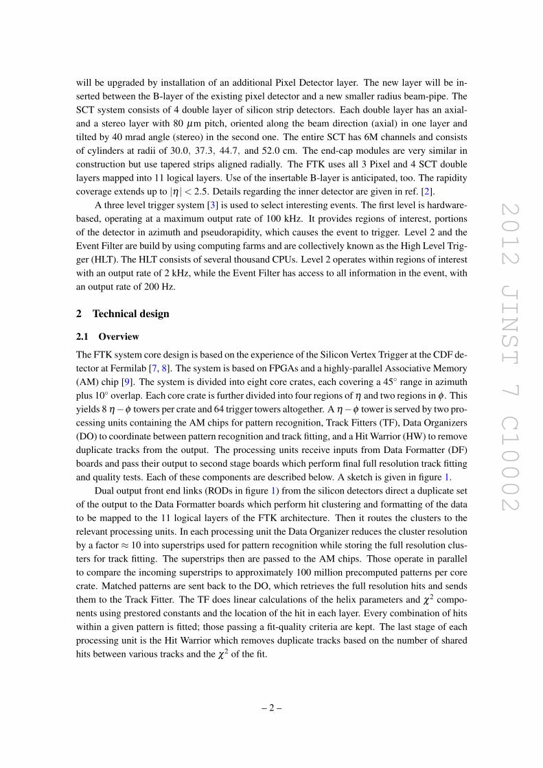
2012 JINST 7 C10002
will be upgraded by installation of an additional Pixel Detector layer The new layer will be in-serted between the B-layer of the existing pixel detector and a new smaller radius beam-pipe TheSCT system consists of 4 double layer of silicon strip detectors Each double layer has an axial-and a stereo layer with 80 microm pitch oriented along the beam direction (axial) in one layer andtilted by 40 mrad angle (stereo) in the second one The entire SCT has 6M channels and consistsof cylinders at radii of 300 373 447 and 520 cm The end-cap modules are very similar inconstruction but use tapered strips aligned radially The FTK uses all 3 Pixel and 4 SCT doublelayers mapped into 11 logical layers Use of the insertable B-layer is anticipated too The rapiditycoverage extends up to |η |lt 25 Details regarding the inner detector are given in ref [2]
A three level trigger system [3] is used to select interesting events The first level is hardware-based operating at a maximum output rate of 100 kHz It provides regions of interest portionsof the detector in azimuth and pseudorapidity which causes the event to trigger Level 2 and theEvent Filter are build by using computing farms and are collectively known as the High Level Trig-ger (HLT) The HLT consists of several thousand CPUs Level 2 operates within regions of interestwith an output rate of 2 kHz while the Event Filter has access to all information in the event withan output rate of 200 Hz
2 Technical design
21 Overview
The FTK system core design is based on the experience of the Silicon Vertex Trigger at the CDF de-tector at Fermilab [7 8] The system is based on FPGAs and a highly-parallel Associative Memory(AM) chip [9] The system is divided into eight core crates each covering a 45 range in azimuthplus 10 overlap Each core crate is further divided into four regions of η and two regions in φ Thisyields 8 ηminusφ towers per crate and 64 trigger towers altogether A ηminusφ tower is served by two pro-cessing units containing the AM chips for pattern recognition Track Fitters (TF) Data Organizers(DO) to coordinate between pattern recognition and track fitting and a Hit Warrior (HW) to removeduplicate tracks from the output The processing units receive inputs from Data Formatter (DF)boards and pass their output to second stage boards which perform final full resolution track fittingand quality tests Each of these components are described below A sketch is given in figure 1
Dual output front end links (RODs in figure 1) from the silicon detectors direct a duplicate setof the output to the Data Formatter boards which perform hit clustering and formatting of the datato be mapped to the 11 logical layers of the FTK architecture Then it routes the clusters to therelevant processing units In each processing unit the Data Organizer reduces the cluster resolutionby a factor asymp 10 into superstrips used for pattern recognition while storing the full resolution clus-ters for track fitting The superstrips then are passed to the AM chips Those operate in parallelto compare the incoming superstrips to approximately 100 million precomputed patterns per corecrate Matched patterns are sent back to the DO which retrieves the full resolution hits and sendsthem to the Track Fitter The TF does linear calculations of the helix parameters and χ2 compo-nents using prestored constants and the location of the hit in each layer Every combination of hitswithin a given pattern is fitted those passing a fit-quality criteria are kept The last stage of eachprocessing unit is the Hit Warrior which removes duplicate tracks based on the number of sharedhits between various tracks and the χ2 of the fit
ndash 2 ndash
2012 JINST 7 C10002
Figure 1 Sketch of the FTK system [1]
22 Pattern recognition and track fitting
FTK tracking is performed in two stages to keep the combinatorics at a manageable level The firststage uses 8 out of 11 silicon layers for pattern recognition and track fitting while the second stagerefits the tracks found in the first stage using all 11 layers The first 8 layer stage uses 3 Pixel 4axial SCT and 1 stereo SCT layer At least seven of eight layers are required to have a hit Thepattern matching takes places in CAM-based custom built AM chips each containing 50k-100kpatterns each Hits entering the system are simultaneously compared to all stored patterns TheAM chips are grouped in sets of 32 chips on a local associative memory board (LAMB) EachAM board contains four LAMBs Once all matched patterns called roads in an event are foundthe information is sent back to the DO The DOs are located on an auxiliary (AUX) card attachedto the AM board Each AUX card has four instances of the Data Organizer Track Fitter and HitWarrior Upon receiving the roads from a LAMB the Data Organizer looks up the full resolutionhits within a road and sends them to the Track Fitter The TF unit is expected to fit one track pernanosecond This high rate is achieved by the large numbers of DSPs in the FPGA used to performa simple linear fit for each set of N hit coordinates x j
pi =N
sumj
ci jx j +qi (21)
The pi are the five helix parameters and the Nminus5 χ2 components all of which are determinedfrom the constants ci j and q j If a fit is above a given χ2 threshold and the candidate track hashits in all the detector layers a majority recovery is performed During this recovery the track isrefitted several times ignoring one of the hits each time to check whether a subset of hits will yielda good χ2 This allows a track to be recovered if one of the hits in the combination comes fromnoise or from a different track The second stage of fitting uses the good tracks from the first stageto look for expected hits in the remaining 3 layers using an inversion of eq (21) If at least 10 outof 11 hits are found the track is refit with all of the hits and subjected to a final fit quality test Thetracking process takes in average about 15 microsec
ndash 3 ndash
2012 JINST 7 C10002
23 Variable resolution patterns
One of the challenges in the design of the FTK is the large number of matched roads expected at3times1034cm2s Although the system is already segmented into independently operating ηminusφ tow-ers the number of matched roads out of the AM could still be a challenge for the Data Organizer atvery high instant luminosities and better pattern matching resolution could be necessary Variable-resolution patterns have been developed to obtain better resolutions with equal AM bank sizes orthe same resolution with much smaller banks [10] Finer-resolution patterns lead to a lower fakerate at the cost of more required AM space while coarse resolution maintains higher efficiencyat the cost of increased combinatorics in the Track Fitter The solution described here maintainsa balance between these considerations The logic of the AM chip design has been upgraded toinclude local subdivisions of each superstrip in a pattern
The ldquodonrsquot carerdquo feature of modern CAMs is implemented so that the width of each patterncan be varied layer by layer This allows the available hardware pattern space to be optimized tomaximize efficiency while minimizing the number of random hits that have to be fit
Simulation studying events with different pile-up conditions have been performed A standardAM bank produces roughly the same number of roads of a variable resolution pattern bank that is3ndash5 times smaller when using a single DC bit in the AM logic [10] At the level of 70 pile-up afairly uniform 900ndash1300 clusters are expected per layer and tower
3 Physics with the FTK
There is a variety of physics applications for the FTK One of the most prominent is the source ofelectroweak symmetry breaking which remains yet unknown The easiest explanation the Higgsmechanism [4ndash6] predicts the Higgs boson whose branching ratios to other particles are dependenton the their masses Therefore the production of heavy particles like b-quarks and τ leptons areof particular interest These couplings can be modified by new physics and their measurementis a crucial test for the Standard Model We will show that particuarly for these final states theFTK system leads to significant improvements In Standard Model measurements the FTK helpsto maintain high efficiencies while controlling background processes at high pile-up
Figure 2 left shows the isolated muon efficiency using the EM calorimeter isolation withtwo different cell energy thresholds as function of the number of pile-up interactions The selec-tion criteria are chosen such that the bb rejection factor is 10 The second plot of the same figuredemonstrates that by applying tracking isolation in contrast to calorimeter isolation the efficiencyimproves Considering only tracks from the muon vertex by applying a selection criteria on thedistance between muon and track at the beamline track the efficiency becomes largely independentof the pile-up These examples demonstrate that tracking can play an important role in identifica-tion of interesting events while maintaining high efficiency With increasing luminosity the use oftracking increases even more The FTK will operate at the Level 1 trigger output rate reconstruct-ing all tracks at near-offline quality for use in the HLT In addition this frees up CPU time in theHLT which can be used for other purposes
ndash 4 ndash
2012 JINST 7 C10002
Pythia Wrarrμν with 2middotnoise cut
0 5 10 15 20 25 30 35 40
0
02
04
06
08
1
12
EM isolation onlybb rejection = 100
Pythia Wrarrμν
1034 pile-up
NUMBER OF PILE-UP INTERACTIONS
SIG
NA
L E
FF
ICIE
NC
Y
0 5 10 15 20 25 30 35 40
0
02
04
06
08
1
12
Pythia WrarrμνPythia Wrarrμν with z0 cut
Tracking isolation onlybb rejection = 100
1034 pile-up
NUMBER OF PILE-UP INTERACTIONS
SIG
NA
L E
FF
ICIE
NC
YFigure 2 Left Isolated muon efficiency using the EM calorimeter isolation with two different cell energythresholds as a function of the number of pile-up interactions for a fixed bb rejection factor of 10 RightIsolated muon efficiency using track isolation with and without a cut on the distance between the track andthe muon at the beamline as a function of the number of pile-up interactions for a fixed bb rejection factorof 10 Signal efficiency here gives the efficiency to select isolated muons Figures from [1]
31 Simulated performance
The FTK system has been simulated in software to determine its expected performance [1] Tracksprovided by the FTK system are compared with tracks reconstructed using the ATLAS offlinetracking algorithm The resolution of track parameters is shown in figure 3 for tracks with |η |lt 1demonstrating that the FTK resolution is comparable to that of the offline tracking
The FTK configuration uses collections of pre-calculated pattern (pattern banks) and linearizedfitting constants suitable for up to 75 pile-up interactions Figure 4 shows the efficiency of the FTKand offline algorithm to reconstruct muons of pT gt 1 GeV The efficiency drops for FTK tracksaround pseudorapidity η = 1 are located at the transition region between barrel detector and for-ward disks These have been addressed by relaxing the number of hits required in these particularregions
The potential for heavy flavor identification (b-tagging) with the FTK tracks at high luminosi-ties is evaluated using an algorithm based on the transverse impact parameter d0 of tracks in jetsTemplate histograms of the impact parameter divided by its uncertainty are created for light jets andb jets These are combined to form a likelihood Figure 5 shows the expected b-quark efficiencyalong with typical light jet rejection factor for FTK and offline tracks Simulated event samples areWHrarr bb Typical b-tagging efficiencies used in analyses are sim 05ndash07
4 Conclusion
The Fast Track Trigger for ATLAS will be able to increase efficiency and control background pro-cesses for particularly interesting events containing b quarks τ leptons and isolated high pT elec-trons and muons This is achieved by using global high speed tracking at the beginning of the
ndash 5 ndash
2012 JINST 7 C10002
RECO - TRUTH CURVATURE (1GeV)00 02 04-02-04E
NT
RIE
S
BIN
000
002
004
006
008OFFLINEFTK
RECO d0 - TRUTH d0 (cm)0
001
002
003
004
0001 002002 001
OFFLINEFTK
EN
TR
IES
B
IN
EN
TR
IES
B
IN
RECO η - TRUTH η0 002 004-004 -002
0
01
02OFFLINEFTK
OFFLINEFTK
EN
TR
IES
B
IN
RECO φ0 - TRUTH φ0 (rad)
002
004
00 0004-0004 0008-0008
OFFLINEFTK
RECO z0 - TRUTH z0 (cm)
EN
TR
IES
B
IN
0
002
004
006
0-004 004 008-008
Figure 3 Comparison of the helix parameters for Offline track reconstruction (black) and FTK (red) Thetrackrsquos transverse momentum is required to exceed 1 GeV and its pseudorapidity is limited to the centralregion (|η |lt 1) A single muon sample is used Figure from [1]
TRUTH pT (GeV)2 4 6 8 10 12 14 16 18 20 22 24
EF
FIC
IEN
CY
0
01
02
03
04
05
06
07
08
09
10
OFFLINEFTK
-2 -15 -1 -05 0 05 1 15 252
EF
FIC
IEN
CY
0
01
02
03
04
05
06
07
08
09
10
TRUTH η
OFFLINEFTK
Figure 4 Comparison between single muon tracking efficiencies for FTK and offline algorithms vs pT
(left) and η (right) Figures from [1]
Level 2 trigger The challenges given by increased combinatorics in track reconstruction with in-creasing luminosity and simultaneously greater need for computational power are solved by usingprecomputed AM based patterns and fast FPGAs in a highly parallel system
A vertical slice test using collision data in summer 2012 is in preparation [11] The dual out-put silicon detector front end cards needed are already installed in ATLAS The full set of dualoutput cards for the final system is already produced A data formatter prototype board is currentlyunder design and will be ready by summer 2012 A prototype input mezzazine [12] is ready for
ndash 6 ndash
2012 JINST 7 C10002
04 05 06 07 08 09 1
LIG
HT
QU
AR
K R
EJE
CT
ION
B TAGGING EFFICIENCY
1
10
210
SIGNED D0 SIGNIFICANCE LIKELIHOODTAGGING PERFORMANCE
3 1034 PILEUPOFFLINEFTK 11L
Figure 5 Light-quark jet rejection vs b-quark jet efficiency for offline and FTK tracks at pile-up as expectedfor a luminosity of asymp 3times 1034 The FTK simulation uses as configuration of 11 layer (11L) Figure fromref [1]
the vertical slice test The AM chip prototype (AMchip04) is expected by early summer 2012 andthe design of the AM board (AMBFTK) is finished An existing board (AMBslim5) [13] will beused for the vertical slice test For the data organizer board a pre-prototype is available and will beused in high-speed testing The second stage board which performs the full 11 layer fit is currentlyundergoing conceptual design and firmware development We expect the system to be operationalin the data taking period following the 2013-2014 shutdown
Acknowledgments
The author thanks the organizers of the WIT2012 workshop for the invitation the FTK collabora-tion and TDAQ speakers committee for their advise preparing the presentation and these proceed-ings The Fast Tracker project receives support from Istituto Nazionale di Fisica Nucleare fromthe US Department of Energy and National Science Foundation from Grant-in-Aid for ScientificResearch by Japan Society for the Promotion of Science from European community FP7 (MarieCurie OIF Project 254410 - ARTLHCFE)
References
[1] A Andreani et al The fast tracker real time processor and its impact on muon isolation tau andb-jet online selections at ATLAS IEEE Trans Nucl Sci 59 (2012) 348
[2] ATLAS collaboration G Aad et al The ATLAS experiment at the CERN Large Hadron Collider2008 JINST 3 S08003
[3] ATLAS collaboration G Aad et al Expected performance of the ATLAS experiment mdash detectortrigger and physics arXiv09010512
[4] F Englert and R Brout Broken symmetry and the mass of gauge vector mesons Phys Rev Lett 13(1964) 321
[5] PW Higgs Broken symmetries and the masses of gauge bosons Phys Rev Lett 13 (1964) 508
ndash 7 ndash
2012 JINST 7 C10002
[6] G Guralnik C Hagen and T Kibble Global conservation laws and massless particles Phys RevLett 13 (1964) 585
[7] J Adelman et al The silicon vertex trigger upgrade at CDF Nucl Instrum Meth A 572 (2007) 361
[8] A Annovi et al A VLSI processor for fast track finding based on content addressable memoriesIEEE Trans Nucl Sci 53 (2006) 2428
[9] M DellrsquoOrso and L Ristori VLSI structures for track finding Nucl Instrum Meth A 278 (1989)436
[10] A Annovi et al A new variable-resolution associative memory for high energy physicsAdvancements in Nuclear Instrumentation Measurement Methods and their Applications (ANIMMA)2011 2nd International Conference on Digital Object Identifier ANIMMA (2011)
[11] A Annovi et al The EDRO board connected to the associative memory ldquobabyrdquo fasttrackerprocessor for the ATLAS experiment in 2nd International Conference on Technology andInstrumentation in Particle Physics Chicago IL USA 9ndash14 June 2011
[12] A Annovi and M Beretta A fast general-purpose clustering algorithm based on FPGAs forhigh-throughput data processing Nucl Instrum Meth A 617 (2010) 254 [arXiv09102572]
[13] A Annovi et al Associative memory design for the Fast Tracker Processor (FTK) at ATLAS IEEENucl Sci Symp Med Imag Conf (NSSMIC) (2011) 141
ndash 8 ndash
- The FTK system
-
- The ATLAS detector and trigger
-
- Technical design
-
- Overview
- Pattern recognition and track fitting
- Variable resolution patterns
-
- Physics with the FTK
-
- Simulated performance
-
- Conclusion
-
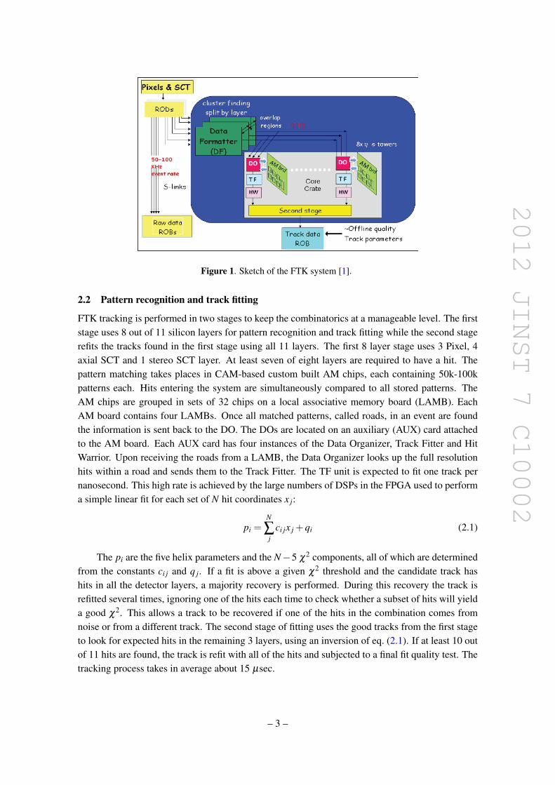
2012 JINST 7 C10002
Figure 1 Sketch of the FTK system [1]
22 Pattern recognition and track fitting
FTK tracking is performed in two stages to keep the combinatorics at a manageable level The firststage uses 8 out of 11 silicon layers for pattern recognition and track fitting while the second stagerefits the tracks found in the first stage using all 11 layers The first 8 layer stage uses 3 Pixel 4axial SCT and 1 stereo SCT layer At least seven of eight layers are required to have a hit Thepattern matching takes places in CAM-based custom built AM chips each containing 50k-100kpatterns each Hits entering the system are simultaneously compared to all stored patterns TheAM chips are grouped in sets of 32 chips on a local associative memory board (LAMB) EachAM board contains four LAMBs Once all matched patterns called roads in an event are foundthe information is sent back to the DO The DOs are located on an auxiliary (AUX) card attachedto the AM board Each AUX card has four instances of the Data Organizer Track Fitter and HitWarrior Upon receiving the roads from a LAMB the Data Organizer looks up the full resolutionhits within a road and sends them to the Track Fitter The TF unit is expected to fit one track pernanosecond This high rate is achieved by the large numbers of DSPs in the FPGA used to performa simple linear fit for each set of N hit coordinates x j
pi =N
sumj
ci jx j +qi (21)
The pi are the five helix parameters and the Nminus5 χ2 components all of which are determinedfrom the constants ci j and q j If a fit is above a given χ2 threshold and the candidate track hashits in all the detector layers a majority recovery is performed During this recovery the track isrefitted several times ignoring one of the hits each time to check whether a subset of hits will yielda good χ2 This allows a track to be recovered if one of the hits in the combination comes fromnoise or from a different track The second stage of fitting uses the good tracks from the first stageto look for expected hits in the remaining 3 layers using an inversion of eq (21) If at least 10 outof 11 hits are found the track is refit with all of the hits and subjected to a final fit quality test Thetracking process takes in average about 15 microsec
ndash 3 ndash
2012 JINST 7 C10002
23 Variable resolution patterns
One of the challenges in the design of the FTK is the large number of matched roads expected at3times1034cm2s Although the system is already segmented into independently operating ηminusφ tow-ers the number of matched roads out of the AM could still be a challenge for the Data Organizer atvery high instant luminosities and better pattern matching resolution could be necessary Variable-resolution patterns have been developed to obtain better resolutions with equal AM bank sizes orthe same resolution with much smaller banks [10] Finer-resolution patterns lead to a lower fakerate at the cost of more required AM space while coarse resolution maintains higher efficiencyat the cost of increased combinatorics in the Track Fitter The solution described here maintainsa balance between these considerations The logic of the AM chip design has been upgraded toinclude local subdivisions of each superstrip in a pattern
The ldquodonrsquot carerdquo feature of modern CAMs is implemented so that the width of each patterncan be varied layer by layer This allows the available hardware pattern space to be optimized tomaximize efficiency while minimizing the number of random hits that have to be fit
Simulation studying events with different pile-up conditions have been performed A standardAM bank produces roughly the same number of roads of a variable resolution pattern bank that is3ndash5 times smaller when using a single DC bit in the AM logic [10] At the level of 70 pile-up afairly uniform 900ndash1300 clusters are expected per layer and tower
3 Physics with the FTK
There is a variety of physics applications for the FTK One of the most prominent is the source ofelectroweak symmetry breaking which remains yet unknown The easiest explanation the Higgsmechanism [4ndash6] predicts the Higgs boson whose branching ratios to other particles are dependenton the their masses Therefore the production of heavy particles like b-quarks and τ leptons areof particular interest These couplings can be modified by new physics and their measurementis a crucial test for the Standard Model We will show that particuarly for these final states theFTK system leads to significant improvements In Standard Model measurements the FTK helpsto maintain high efficiencies while controlling background processes at high pile-up
Figure 2 left shows the isolated muon efficiency using the EM calorimeter isolation withtwo different cell energy thresholds as function of the number of pile-up interactions The selec-tion criteria are chosen such that the bb rejection factor is 10 The second plot of the same figuredemonstrates that by applying tracking isolation in contrast to calorimeter isolation the efficiencyimproves Considering only tracks from the muon vertex by applying a selection criteria on thedistance between muon and track at the beamline track the efficiency becomes largely independentof the pile-up These examples demonstrate that tracking can play an important role in identifica-tion of interesting events while maintaining high efficiency With increasing luminosity the use oftracking increases even more The FTK will operate at the Level 1 trigger output rate reconstruct-ing all tracks at near-offline quality for use in the HLT In addition this frees up CPU time in theHLT which can be used for other purposes
ndash 4 ndash
2012 JINST 7 C10002
Pythia Wrarrμν with 2middotnoise cut
0 5 10 15 20 25 30 35 40
0
02
04
06
08
1
12
EM isolation onlybb rejection = 100
Pythia Wrarrμν
1034 pile-up
NUMBER OF PILE-UP INTERACTIONS
SIG
NA
L E
FF
ICIE
NC
Y
0 5 10 15 20 25 30 35 40
0
02
04
06
08
1
12
Pythia WrarrμνPythia Wrarrμν with z0 cut
Tracking isolation onlybb rejection = 100
1034 pile-up
NUMBER OF PILE-UP INTERACTIONS
SIG
NA
L E
FF
ICIE
NC
YFigure 2 Left Isolated muon efficiency using the EM calorimeter isolation with two different cell energythresholds as a function of the number of pile-up interactions for a fixed bb rejection factor of 10 RightIsolated muon efficiency using track isolation with and without a cut on the distance between the track andthe muon at the beamline as a function of the number of pile-up interactions for a fixed bb rejection factorof 10 Signal efficiency here gives the efficiency to select isolated muons Figures from [1]
31 Simulated performance
The FTK system has been simulated in software to determine its expected performance [1] Tracksprovided by the FTK system are compared with tracks reconstructed using the ATLAS offlinetracking algorithm The resolution of track parameters is shown in figure 3 for tracks with |η |lt 1demonstrating that the FTK resolution is comparable to that of the offline tracking
The FTK configuration uses collections of pre-calculated pattern (pattern banks) and linearizedfitting constants suitable for up to 75 pile-up interactions Figure 4 shows the efficiency of the FTKand offline algorithm to reconstruct muons of pT gt 1 GeV The efficiency drops for FTK tracksaround pseudorapidity η = 1 are located at the transition region between barrel detector and for-ward disks These have been addressed by relaxing the number of hits required in these particularregions
The potential for heavy flavor identification (b-tagging) with the FTK tracks at high luminosi-ties is evaluated using an algorithm based on the transverse impact parameter d0 of tracks in jetsTemplate histograms of the impact parameter divided by its uncertainty are created for light jets andb jets These are combined to form a likelihood Figure 5 shows the expected b-quark efficiencyalong with typical light jet rejection factor for FTK and offline tracks Simulated event samples areWHrarr bb Typical b-tagging efficiencies used in analyses are sim 05ndash07
4 Conclusion
The Fast Track Trigger for ATLAS will be able to increase efficiency and control background pro-cesses for particularly interesting events containing b quarks τ leptons and isolated high pT elec-trons and muons This is achieved by using global high speed tracking at the beginning of the
ndash 5 ndash
2012 JINST 7 C10002
RECO - TRUTH CURVATURE (1GeV)00 02 04-02-04E
NT
RIE
S
BIN
000
002
004
006
008OFFLINEFTK
RECO d0 - TRUTH d0 (cm)0
001
002
003
004
0001 002002 001
OFFLINEFTK
EN
TR
IES
B
IN
EN
TR
IES
B
IN
RECO η - TRUTH η0 002 004-004 -002
0
01
02OFFLINEFTK
OFFLINEFTK
EN
TR
IES
B
IN
RECO φ0 - TRUTH φ0 (rad)
002
004
00 0004-0004 0008-0008
OFFLINEFTK
RECO z0 - TRUTH z0 (cm)
EN
TR
IES
B
IN
0
002
004
006
0-004 004 008-008
Figure 3 Comparison of the helix parameters for Offline track reconstruction (black) and FTK (red) Thetrackrsquos transverse momentum is required to exceed 1 GeV and its pseudorapidity is limited to the centralregion (|η |lt 1) A single muon sample is used Figure from [1]
TRUTH pT (GeV)2 4 6 8 10 12 14 16 18 20 22 24
EF
FIC
IEN
CY
0
01
02
03
04
05
06
07
08
09
10
OFFLINEFTK
-2 -15 -1 -05 0 05 1 15 252
EF
FIC
IEN
CY
0
01
02
03
04
05
06
07
08
09
10
TRUTH η
OFFLINEFTK
Figure 4 Comparison between single muon tracking efficiencies for FTK and offline algorithms vs pT
(left) and η (right) Figures from [1]
Level 2 trigger The challenges given by increased combinatorics in track reconstruction with in-creasing luminosity and simultaneously greater need for computational power are solved by usingprecomputed AM based patterns and fast FPGAs in a highly parallel system
A vertical slice test using collision data in summer 2012 is in preparation [11] The dual out-put silicon detector front end cards needed are already installed in ATLAS The full set of dualoutput cards for the final system is already produced A data formatter prototype board is currentlyunder design and will be ready by summer 2012 A prototype input mezzazine [12] is ready for
ndash 6 ndash
2012 JINST 7 C10002
04 05 06 07 08 09 1
LIG
HT
QU
AR
K R
EJE
CT
ION
B TAGGING EFFICIENCY
1
10
210
SIGNED D0 SIGNIFICANCE LIKELIHOODTAGGING PERFORMANCE
3 1034 PILEUPOFFLINEFTK 11L
Figure 5 Light-quark jet rejection vs b-quark jet efficiency for offline and FTK tracks at pile-up as expectedfor a luminosity of asymp 3times 1034 The FTK simulation uses as configuration of 11 layer (11L) Figure fromref [1]
the vertical slice test The AM chip prototype (AMchip04) is expected by early summer 2012 andthe design of the AM board (AMBFTK) is finished An existing board (AMBslim5) [13] will beused for the vertical slice test For the data organizer board a pre-prototype is available and will beused in high-speed testing The second stage board which performs the full 11 layer fit is currentlyundergoing conceptual design and firmware development We expect the system to be operationalin the data taking period following the 2013-2014 shutdown
Acknowledgments
The author thanks the organizers of the WIT2012 workshop for the invitation the FTK collabora-tion and TDAQ speakers committee for their advise preparing the presentation and these proceed-ings The Fast Tracker project receives support from Istituto Nazionale di Fisica Nucleare fromthe US Department of Energy and National Science Foundation from Grant-in-Aid for ScientificResearch by Japan Society for the Promotion of Science from European community FP7 (MarieCurie OIF Project 254410 - ARTLHCFE)
References
[1] A Andreani et al The fast tracker real time processor and its impact on muon isolation tau andb-jet online selections at ATLAS IEEE Trans Nucl Sci 59 (2012) 348
[2] ATLAS collaboration G Aad et al The ATLAS experiment at the CERN Large Hadron Collider2008 JINST 3 S08003
[3] ATLAS collaboration G Aad et al Expected performance of the ATLAS experiment mdash detectortrigger and physics arXiv09010512
[4] F Englert and R Brout Broken symmetry and the mass of gauge vector mesons Phys Rev Lett 13(1964) 321
[5] PW Higgs Broken symmetries and the masses of gauge bosons Phys Rev Lett 13 (1964) 508
ndash 7 ndash
2012 JINST 7 C10002
[6] G Guralnik C Hagen and T Kibble Global conservation laws and massless particles Phys RevLett 13 (1964) 585
[7] J Adelman et al The silicon vertex trigger upgrade at CDF Nucl Instrum Meth A 572 (2007) 361
[8] A Annovi et al A VLSI processor for fast track finding based on content addressable memoriesIEEE Trans Nucl Sci 53 (2006) 2428
[9] M DellrsquoOrso and L Ristori VLSI structures for track finding Nucl Instrum Meth A 278 (1989)436
[10] A Annovi et al A new variable-resolution associative memory for high energy physicsAdvancements in Nuclear Instrumentation Measurement Methods and their Applications (ANIMMA)2011 2nd International Conference on Digital Object Identifier ANIMMA (2011)
[11] A Annovi et al The EDRO board connected to the associative memory ldquobabyrdquo fasttrackerprocessor for the ATLAS experiment in 2nd International Conference on Technology andInstrumentation in Particle Physics Chicago IL USA 9ndash14 June 2011
[12] A Annovi and M Beretta A fast general-purpose clustering algorithm based on FPGAs forhigh-throughput data processing Nucl Instrum Meth A 617 (2010) 254 [arXiv09102572]
[13] A Annovi et al Associative memory design for the Fast Tracker Processor (FTK) at ATLAS IEEENucl Sci Symp Med Imag Conf (NSSMIC) (2011) 141
ndash 8 ndash
- The FTK system
-
- The ATLAS detector and trigger
-
- Technical design
-
- Overview
- Pattern recognition and track fitting
- Variable resolution patterns
-
- Physics with the FTK
-
- Simulated performance
-
- Conclusion
-
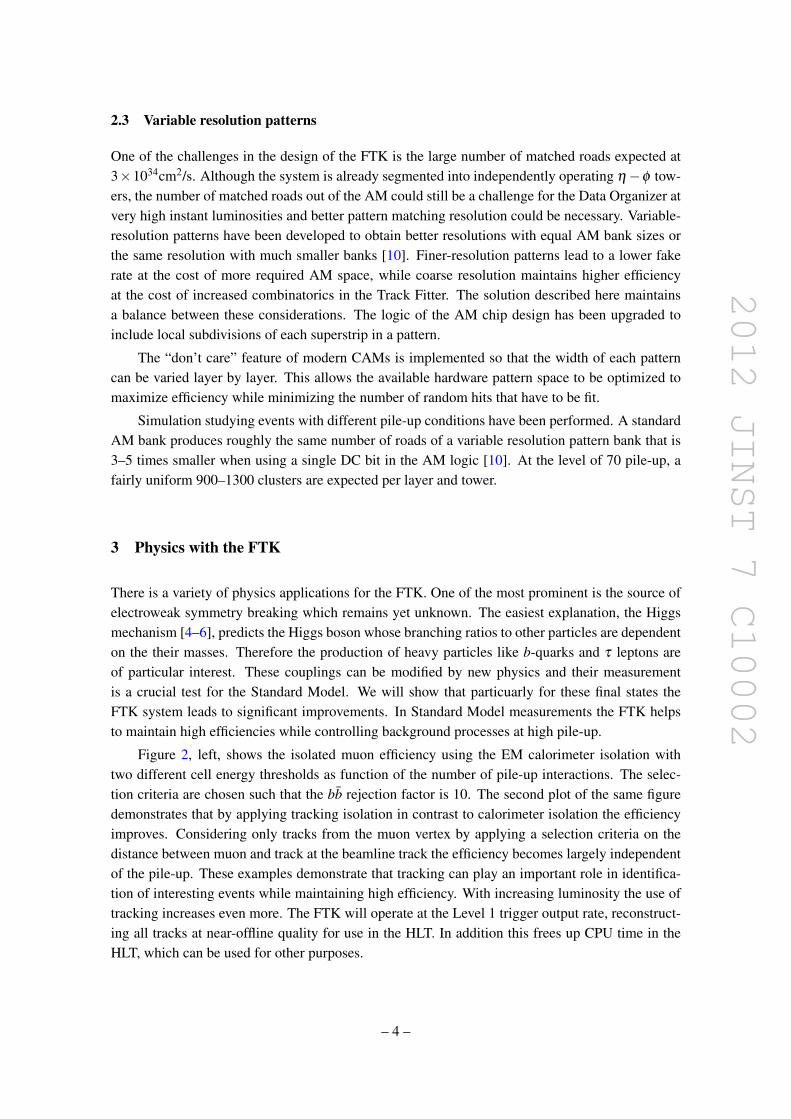
2012 JINST 7 C10002
23 Variable resolution patterns
One of the challenges in the design of the FTK is the large number of matched roads expected at3times1034cm2s Although the system is already segmented into independently operating ηminusφ tow-ers the number of matched roads out of the AM could still be a challenge for the Data Organizer atvery high instant luminosities and better pattern matching resolution could be necessary Variable-resolution patterns have been developed to obtain better resolutions with equal AM bank sizes orthe same resolution with much smaller banks [10] Finer-resolution patterns lead to a lower fakerate at the cost of more required AM space while coarse resolution maintains higher efficiencyat the cost of increased combinatorics in the Track Fitter The solution described here maintainsa balance between these considerations The logic of the AM chip design has been upgraded toinclude local subdivisions of each superstrip in a pattern
The ldquodonrsquot carerdquo feature of modern CAMs is implemented so that the width of each patterncan be varied layer by layer This allows the available hardware pattern space to be optimized tomaximize efficiency while minimizing the number of random hits that have to be fit
Simulation studying events with different pile-up conditions have been performed A standardAM bank produces roughly the same number of roads of a variable resolution pattern bank that is3ndash5 times smaller when using a single DC bit in the AM logic [10] At the level of 70 pile-up afairly uniform 900ndash1300 clusters are expected per layer and tower
3 Physics with the FTK
There is a variety of physics applications for the FTK One of the most prominent is the source ofelectroweak symmetry breaking which remains yet unknown The easiest explanation the Higgsmechanism [4ndash6] predicts the Higgs boson whose branching ratios to other particles are dependenton the their masses Therefore the production of heavy particles like b-quarks and τ leptons areof particular interest These couplings can be modified by new physics and their measurementis a crucial test for the Standard Model We will show that particuarly for these final states theFTK system leads to significant improvements In Standard Model measurements the FTK helpsto maintain high efficiencies while controlling background processes at high pile-up
Figure 2 left shows the isolated muon efficiency using the EM calorimeter isolation withtwo different cell energy thresholds as function of the number of pile-up interactions The selec-tion criteria are chosen such that the bb rejection factor is 10 The second plot of the same figuredemonstrates that by applying tracking isolation in contrast to calorimeter isolation the efficiencyimproves Considering only tracks from the muon vertex by applying a selection criteria on thedistance between muon and track at the beamline track the efficiency becomes largely independentof the pile-up These examples demonstrate that tracking can play an important role in identifica-tion of interesting events while maintaining high efficiency With increasing luminosity the use oftracking increases even more The FTK will operate at the Level 1 trigger output rate reconstruct-ing all tracks at near-offline quality for use in the HLT In addition this frees up CPU time in theHLT which can be used for other purposes
ndash 4 ndash
2012 JINST 7 C10002
Pythia Wrarrμν with 2middotnoise cut
0 5 10 15 20 25 30 35 40
0
02
04
06
08
1
12
EM isolation onlybb rejection = 100
Pythia Wrarrμν
1034 pile-up
NUMBER OF PILE-UP INTERACTIONS
SIG
NA
L E
FF
ICIE
NC
Y
0 5 10 15 20 25 30 35 40
0
02
04
06
08
1
12
Pythia WrarrμνPythia Wrarrμν with z0 cut
Tracking isolation onlybb rejection = 100
1034 pile-up
NUMBER OF PILE-UP INTERACTIONS
SIG
NA
L E
FF
ICIE
NC
YFigure 2 Left Isolated muon efficiency using the EM calorimeter isolation with two different cell energythresholds as a function of the number of pile-up interactions for a fixed bb rejection factor of 10 RightIsolated muon efficiency using track isolation with and without a cut on the distance between the track andthe muon at the beamline as a function of the number of pile-up interactions for a fixed bb rejection factorof 10 Signal efficiency here gives the efficiency to select isolated muons Figures from [1]
31 Simulated performance
The FTK system has been simulated in software to determine its expected performance [1] Tracksprovided by the FTK system are compared with tracks reconstructed using the ATLAS offlinetracking algorithm The resolution of track parameters is shown in figure 3 for tracks with |η |lt 1demonstrating that the FTK resolution is comparable to that of the offline tracking
The FTK configuration uses collections of pre-calculated pattern (pattern banks) and linearizedfitting constants suitable for up to 75 pile-up interactions Figure 4 shows the efficiency of the FTKand offline algorithm to reconstruct muons of pT gt 1 GeV The efficiency drops for FTK tracksaround pseudorapidity η = 1 are located at the transition region between barrel detector and for-ward disks These have been addressed by relaxing the number of hits required in these particularregions
The potential for heavy flavor identification (b-tagging) with the FTK tracks at high luminosi-ties is evaluated using an algorithm based on the transverse impact parameter d0 of tracks in jetsTemplate histograms of the impact parameter divided by its uncertainty are created for light jets andb jets These are combined to form a likelihood Figure 5 shows the expected b-quark efficiencyalong with typical light jet rejection factor for FTK and offline tracks Simulated event samples areWHrarr bb Typical b-tagging efficiencies used in analyses are sim 05ndash07
4 Conclusion
The Fast Track Trigger for ATLAS will be able to increase efficiency and control background pro-cesses for particularly interesting events containing b quarks τ leptons and isolated high pT elec-trons and muons This is achieved by using global high speed tracking at the beginning of the
ndash 5 ndash
2012 JINST 7 C10002
RECO - TRUTH CURVATURE (1GeV)00 02 04-02-04E
NT
RIE
S
BIN
000
002
004
006
008OFFLINEFTK
RECO d0 - TRUTH d0 (cm)0
001
002
003
004
0001 002002 001
OFFLINEFTK
EN
TR
IES
B
IN
EN
TR
IES
B
IN
RECO η - TRUTH η0 002 004-004 -002
0
01
02OFFLINEFTK
OFFLINEFTK
EN
TR
IES
B
IN
RECO φ0 - TRUTH φ0 (rad)
002
004
00 0004-0004 0008-0008
OFFLINEFTK
RECO z0 - TRUTH z0 (cm)
EN
TR
IES
B
IN
0
002
004
006
0-004 004 008-008
Figure 3 Comparison of the helix parameters for Offline track reconstruction (black) and FTK (red) Thetrackrsquos transverse momentum is required to exceed 1 GeV and its pseudorapidity is limited to the centralregion (|η |lt 1) A single muon sample is used Figure from [1]
TRUTH pT (GeV)2 4 6 8 10 12 14 16 18 20 22 24
EF
FIC
IEN
CY
0
01
02
03
04
05
06
07
08
09
10
OFFLINEFTK
-2 -15 -1 -05 0 05 1 15 252
EF
FIC
IEN
CY
0
01
02
03
04
05
06
07
08
09
10
TRUTH η
OFFLINEFTK
Figure 4 Comparison between single muon tracking efficiencies for FTK and offline algorithms vs pT
(left) and η (right) Figures from [1]
Level 2 trigger The challenges given by increased combinatorics in track reconstruction with in-creasing luminosity and simultaneously greater need for computational power are solved by usingprecomputed AM based patterns and fast FPGAs in a highly parallel system
A vertical slice test using collision data in summer 2012 is in preparation [11] The dual out-put silicon detector front end cards needed are already installed in ATLAS The full set of dualoutput cards for the final system is already produced A data formatter prototype board is currentlyunder design and will be ready by summer 2012 A prototype input mezzazine [12] is ready for
ndash 6 ndash
2012 JINST 7 C10002
04 05 06 07 08 09 1
LIG
HT
QU
AR
K R
EJE
CT
ION
B TAGGING EFFICIENCY
1
10
210
SIGNED D0 SIGNIFICANCE LIKELIHOODTAGGING PERFORMANCE
3 1034 PILEUPOFFLINEFTK 11L
Figure 5 Light-quark jet rejection vs b-quark jet efficiency for offline and FTK tracks at pile-up as expectedfor a luminosity of asymp 3times 1034 The FTK simulation uses as configuration of 11 layer (11L) Figure fromref [1]
the vertical slice test The AM chip prototype (AMchip04) is expected by early summer 2012 andthe design of the AM board (AMBFTK) is finished An existing board (AMBslim5) [13] will beused for the vertical slice test For the data organizer board a pre-prototype is available and will beused in high-speed testing The second stage board which performs the full 11 layer fit is currentlyundergoing conceptual design and firmware development We expect the system to be operationalin the data taking period following the 2013-2014 shutdown
Acknowledgments
The author thanks the organizers of the WIT2012 workshop for the invitation the FTK collabora-tion and TDAQ speakers committee for their advise preparing the presentation and these proceed-ings The Fast Tracker project receives support from Istituto Nazionale di Fisica Nucleare fromthe US Department of Energy and National Science Foundation from Grant-in-Aid for ScientificResearch by Japan Society for the Promotion of Science from European community FP7 (MarieCurie OIF Project 254410 - ARTLHCFE)
References
[1] A Andreani et al The fast tracker real time processor and its impact on muon isolation tau andb-jet online selections at ATLAS IEEE Trans Nucl Sci 59 (2012) 348
[2] ATLAS collaboration G Aad et al The ATLAS experiment at the CERN Large Hadron Collider2008 JINST 3 S08003
[3] ATLAS collaboration G Aad et al Expected performance of the ATLAS experiment mdash detectortrigger and physics arXiv09010512
[4] F Englert and R Brout Broken symmetry and the mass of gauge vector mesons Phys Rev Lett 13(1964) 321
[5] PW Higgs Broken symmetries and the masses of gauge bosons Phys Rev Lett 13 (1964) 508
ndash 7 ndash
2012 JINST 7 C10002
[6] G Guralnik C Hagen and T Kibble Global conservation laws and massless particles Phys RevLett 13 (1964) 585
[7] J Adelman et al The silicon vertex trigger upgrade at CDF Nucl Instrum Meth A 572 (2007) 361
[8] A Annovi et al A VLSI processor for fast track finding based on content addressable memoriesIEEE Trans Nucl Sci 53 (2006) 2428
[9] M DellrsquoOrso and L Ristori VLSI structures for track finding Nucl Instrum Meth A 278 (1989)436
[10] A Annovi et al A new variable-resolution associative memory for high energy physicsAdvancements in Nuclear Instrumentation Measurement Methods and their Applications (ANIMMA)2011 2nd International Conference on Digital Object Identifier ANIMMA (2011)
[11] A Annovi et al The EDRO board connected to the associative memory ldquobabyrdquo fasttrackerprocessor for the ATLAS experiment in 2nd International Conference on Technology andInstrumentation in Particle Physics Chicago IL USA 9ndash14 June 2011
[12] A Annovi and M Beretta A fast general-purpose clustering algorithm based on FPGAs forhigh-throughput data processing Nucl Instrum Meth A 617 (2010) 254 [arXiv09102572]
[13] A Annovi et al Associative memory design for the Fast Tracker Processor (FTK) at ATLAS IEEENucl Sci Symp Med Imag Conf (NSSMIC) (2011) 141
ndash 8 ndash
- The FTK system
-
- The ATLAS detector and trigger
-
- Technical design
-
- Overview
- Pattern recognition and track fitting
- Variable resolution patterns
-
- Physics with the FTK
-
- Simulated performance
-
- Conclusion
-
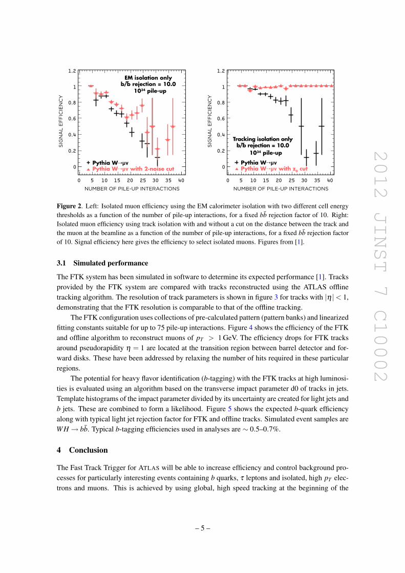
2012 JINST 7 C10002
Pythia Wrarrμν with 2middotnoise cut
0 5 10 15 20 25 30 35 40
0
02
04
06
08
1
12
EM isolation onlybb rejection = 100
Pythia Wrarrμν
1034 pile-up
NUMBER OF PILE-UP INTERACTIONS
SIG
NA
L E
FF
ICIE
NC
Y
0 5 10 15 20 25 30 35 40
0
02
04
06
08
1
12
Pythia WrarrμνPythia Wrarrμν with z0 cut
Tracking isolation onlybb rejection = 100
1034 pile-up
NUMBER OF PILE-UP INTERACTIONS
SIG
NA
L E
FF
ICIE
NC
YFigure 2 Left Isolated muon efficiency using the EM calorimeter isolation with two different cell energythresholds as a function of the number of pile-up interactions for a fixed bb rejection factor of 10 RightIsolated muon efficiency using track isolation with and without a cut on the distance between the track andthe muon at the beamline as a function of the number of pile-up interactions for a fixed bb rejection factorof 10 Signal efficiency here gives the efficiency to select isolated muons Figures from [1]
31 Simulated performance
The FTK system has been simulated in software to determine its expected performance [1] Tracksprovided by the FTK system are compared with tracks reconstructed using the ATLAS offlinetracking algorithm The resolution of track parameters is shown in figure 3 for tracks with |η |lt 1demonstrating that the FTK resolution is comparable to that of the offline tracking
The FTK configuration uses collections of pre-calculated pattern (pattern banks) and linearizedfitting constants suitable for up to 75 pile-up interactions Figure 4 shows the efficiency of the FTKand offline algorithm to reconstruct muons of pT gt 1 GeV The efficiency drops for FTK tracksaround pseudorapidity η = 1 are located at the transition region between barrel detector and for-ward disks These have been addressed by relaxing the number of hits required in these particularregions
The potential for heavy flavor identification (b-tagging) with the FTK tracks at high luminosi-ties is evaluated using an algorithm based on the transverse impact parameter d0 of tracks in jetsTemplate histograms of the impact parameter divided by its uncertainty are created for light jets andb jets These are combined to form a likelihood Figure 5 shows the expected b-quark efficiencyalong with typical light jet rejection factor for FTK and offline tracks Simulated event samples areWHrarr bb Typical b-tagging efficiencies used in analyses are sim 05ndash07
4 Conclusion
The Fast Track Trigger for ATLAS will be able to increase efficiency and control background pro-cesses for particularly interesting events containing b quarks τ leptons and isolated high pT elec-trons and muons This is achieved by using global high speed tracking at the beginning of the
ndash 5 ndash
2012 JINST 7 C10002
RECO - TRUTH CURVATURE (1GeV)00 02 04-02-04E
NT
RIE
S
BIN
000
002
004
006
008OFFLINEFTK
RECO d0 - TRUTH d0 (cm)0
001
002
003
004
0001 002002 001
OFFLINEFTK
EN
TR
IES
B
IN
EN
TR
IES
B
IN
RECO η - TRUTH η0 002 004-004 -002
0
01
02OFFLINEFTK
OFFLINEFTK
EN
TR
IES
B
IN
RECO φ0 - TRUTH φ0 (rad)
002
004
00 0004-0004 0008-0008
OFFLINEFTK
RECO z0 - TRUTH z0 (cm)
EN
TR
IES
B
IN
0
002
004
006
0-004 004 008-008
Figure 3 Comparison of the helix parameters for Offline track reconstruction (black) and FTK (red) Thetrackrsquos transverse momentum is required to exceed 1 GeV and its pseudorapidity is limited to the centralregion (|η |lt 1) A single muon sample is used Figure from [1]
TRUTH pT (GeV)2 4 6 8 10 12 14 16 18 20 22 24
EF
FIC
IEN
CY
0
01
02
03
04
05
06
07
08
09
10
OFFLINEFTK
-2 -15 -1 -05 0 05 1 15 252
EF
FIC
IEN
CY
0
01
02
03
04
05
06
07
08
09
10
TRUTH η
OFFLINEFTK
Figure 4 Comparison between single muon tracking efficiencies for FTK and offline algorithms vs pT
(left) and η (right) Figures from [1]
Level 2 trigger The challenges given by increased combinatorics in track reconstruction with in-creasing luminosity and simultaneously greater need for computational power are solved by usingprecomputed AM based patterns and fast FPGAs in a highly parallel system
A vertical slice test using collision data in summer 2012 is in preparation [11] The dual out-put silicon detector front end cards needed are already installed in ATLAS The full set of dualoutput cards for the final system is already produced A data formatter prototype board is currentlyunder design and will be ready by summer 2012 A prototype input mezzazine [12] is ready for
ndash 6 ndash
2012 JINST 7 C10002
04 05 06 07 08 09 1
LIG
HT
QU
AR
K R
EJE
CT
ION
B TAGGING EFFICIENCY
1
10
210
SIGNED D0 SIGNIFICANCE LIKELIHOODTAGGING PERFORMANCE
3 1034 PILEUPOFFLINEFTK 11L
Figure 5 Light-quark jet rejection vs b-quark jet efficiency for offline and FTK tracks at pile-up as expectedfor a luminosity of asymp 3times 1034 The FTK simulation uses as configuration of 11 layer (11L) Figure fromref [1]
the vertical slice test The AM chip prototype (AMchip04) is expected by early summer 2012 andthe design of the AM board (AMBFTK) is finished An existing board (AMBslim5) [13] will beused for the vertical slice test For the data organizer board a pre-prototype is available and will beused in high-speed testing The second stage board which performs the full 11 layer fit is currentlyundergoing conceptual design and firmware development We expect the system to be operationalin the data taking period following the 2013-2014 shutdown
Acknowledgments
The author thanks the organizers of the WIT2012 workshop for the invitation the FTK collabora-tion and TDAQ speakers committee for their advise preparing the presentation and these proceed-ings The Fast Tracker project receives support from Istituto Nazionale di Fisica Nucleare fromthe US Department of Energy and National Science Foundation from Grant-in-Aid for ScientificResearch by Japan Society for the Promotion of Science from European community FP7 (MarieCurie OIF Project 254410 - ARTLHCFE)
References
[1] A Andreani et al The fast tracker real time processor and its impact on muon isolation tau andb-jet online selections at ATLAS IEEE Trans Nucl Sci 59 (2012) 348
[2] ATLAS collaboration G Aad et al The ATLAS experiment at the CERN Large Hadron Collider2008 JINST 3 S08003
[3] ATLAS collaboration G Aad et al Expected performance of the ATLAS experiment mdash detectortrigger and physics arXiv09010512
[4] F Englert and R Brout Broken symmetry and the mass of gauge vector mesons Phys Rev Lett 13(1964) 321
[5] PW Higgs Broken symmetries and the masses of gauge bosons Phys Rev Lett 13 (1964) 508
ndash 7 ndash
2012 JINST 7 C10002
[6] G Guralnik C Hagen and T Kibble Global conservation laws and massless particles Phys RevLett 13 (1964) 585
[7] J Adelman et al The silicon vertex trigger upgrade at CDF Nucl Instrum Meth A 572 (2007) 361
[8] A Annovi et al A VLSI processor for fast track finding based on content addressable memoriesIEEE Trans Nucl Sci 53 (2006) 2428
[9] M DellrsquoOrso and L Ristori VLSI structures for track finding Nucl Instrum Meth A 278 (1989)436
[10] A Annovi et al A new variable-resolution associative memory for high energy physicsAdvancements in Nuclear Instrumentation Measurement Methods and their Applications (ANIMMA)2011 2nd International Conference on Digital Object Identifier ANIMMA (2011)
[11] A Annovi et al The EDRO board connected to the associative memory ldquobabyrdquo fasttrackerprocessor for the ATLAS experiment in 2nd International Conference on Technology andInstrumentation in Particle Physics Chicago IL USA 9ndash14 June 2011
[12] A Annovi and M Beretta A fast general-purpose clustering algorithm based on FPGAs forhigh-throughput data processing Nucl Instrum Meth A 617 (2010) 254 [arXiv09102572]
[13] A Annovi et al Associative memory design for the Fast Tracker Processor (FTK) at ATLAS IEEENucl Sci Symp Med Imag Conf (NSSMIC) (2011) 141
ndash 8 ndash
- The FTK system
-
- The ATLAS detector and trigger
-
- Technical design
-
- Overview
- Pattern recognition and track fitting
- Variable resolution patterns
-
- Physics with the FTK
-
- Simulated performance
-
- Conclusion
-
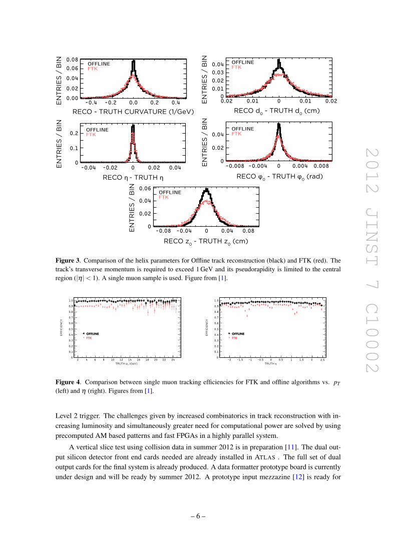
2012 JINST 7 C10002
RECO - TRUTH CURVATURE (1GeV)00 02 04-02-04E
NT
RIE
S
BIN
000
002
004
006
008OFFLINEFTK
RECO d0 - TRUTH d0 (cm)0
001
002
003
004
0001 002002 001
OFFLINEFTK
EN
TR
IES
B
IN
EN
TR
IES
B
IN
RECO η - TRUTH η0 002 004-004 -002
0
01
02OFFLINEFTK
OFFLINEFTK
EN
TR
IES
B
IN
RECO φ0 - TRUTH φ0 (rad)
002
004
00 0004-0004 0008-0008
OFFLINEFTK
RECO z0 - TRUTH z0 (cm)
EN
TR
IES
B
IN
0
002
004
006
0-004 004 008-008
Figure 3 Comparison of the helix parameters for Offline track reconstruction (black) and FTK (red) Thetrackrsquos transverse momentum is required to exceed 1 GeV and its pseudorapidity is limited to the centralregion (|η |lt 1) A single muon sample is used Figure from [1]
TRUTH pT (GeV)2 4 6 8 10 12 14 16 18 20 22 24
EF
FIC
IEN
CY
0
01
02
03
04
05
06
07
08
09
10
OFFLINEFTK
-2 -15 -1 -05 0 05 1 15 252
EF
FIC
IEN
CY
0
01
02
03
04
05
06
07
08
09
10
TRUTH η
OFFLINEFTK
Figure 4 Comparison between single muon tracking efficiencies for FTK and offline algorithms vs pT
(left) and η (right) Figures from [1]
Level 2 trigger The challenges given by increased combinatorics in track reconstruction with in-creasing luminosity and simultaneously greater need for computational power are solved by usingprecomputed AM based patterns and fast FPGAs in a highly parallel system
A vertical slice test using collision data in summer 2012 is in preparation [11] The dual out-put silicon detector front end cards needed are already installed in ATLAS The full set of dualoutput cards for the final system is already produced A data formatter prototype board is currentlyunder design and will be ready by summer 2012 A prototype input mezzazine [12] is ready for
ndash 6 ndash
2012 JINST 7 C10002
04 05 06 07 08 09 1
LIG
HT
QU
AR
K R
EJE
CT
ION
B TAGGING EFFICIENCY
1
10
210
SIGNED D0 SIGNIFICANCE LIKELIHOODTAGGING PERFORMANCE
3 1034 PILEUPOFFLINEFTK 11L
Figure 5 Light-quark jet rejection vs b-quark jet efficiency for offline and FTK tracks at pile-up as expectedfor a luminosity of asymp 3times 1034 The FTK simulation uses as configuration of 11 layer (11L) Figure fromref [1]
the vertical slice test The AM chip prototype (AMchip04) is expected by early summer 2012 andthe design of the AM board (AMBFTK) is finished An existing board (AMBslim5) [13] will beused for the vertical slice test For the data organizer board a pre-prototype is available and will beused in high-speed testing The second stage board which performs the full 11 layer fit is currentlyundergoing conceptual design and firmware development We expect the system to be operationalin the data taking period following the 2013-2014 shutdown
Acknowledgments
The author thanks the organizers of the WIT2012 workshop for the invitation the FTK collabora-tion and TDAQ speakers committee for their advise preparing the presentation and these proceed-ings The Fast Tracker project receives support from Istituto Nazionale di Fisica Nucleare fromthe US Department of Energy and National Science Foundation from Grant-in-Aid for ScientificResearch by Japan Society for the Promotion of Science from European community FP7 (MarieCurie OIF Project 254410 - ARTLHCFE)
References
[1] A Andreani et al The fast tracker real time processor and its impact on muon isolation tau andb-jet online selections at ATLAS IEEE Trans Nucl Sci 59 (2012) 348
[2] ATLAS collaboration G Aad et al The ATLAS experiment at the CERN Large Hadron Collider2008 JINST 3 S08003
[3] ATLAS collaboration G Aad et al Expected performance of the ATLAS experiment mdash detectortrigger and physics arXiv09010512
[4] F Englert and R Brout Broken symmetry and the mass of gauge vector mesons Phys Rev Lett 13(1964) 321
[5] PW Higgs Broken symmetries and the masses of gauge bosons Phys Rev Lett 13 (1964) 508
ndash 7 ndash
2012 JINST 7 C10002
[6] G Guralnik C Hagen and T Kibble Global conservation laws and massless particles Phys RevLett 13 (1964) 585
[7] J Adelman et al The silicon vertex trigger upgrade at CDF Nucl Instrum Meth A 572 (2007) 361
[8] A Annovi et al A VLSI processor for fast track finding based on content addressable memoriesIEEE Trans Nucl Sci 53 (2006) 2428
[9] M DellrsquoOrso and L Ristori VLSI structures for track finding Nucl Instrum Meth A 278 (1989)436
[10] A Annovi et al A new variable-resolution associative memory for high energy physicsAdvancements in Nuclear Instrumentation Measurement Methods and their Applications (ANIMMA)2011 2nd International Conference on Digital Object Identifier ANIMMA (2011)
[11] A Annovi et al The EDRO board connected to the associative memory ldquobabyrdquo fasttrackerprocessor for the ATLAS experiment in 2nd International Conference on Technology andInstrumentation in Particle Physics Chicago IL USA 9ndash14 June 2011
[12] A Annovi and M Beretta A fast general-purpose clustering algorithm based on FPGAs forhigh-throughput data processing Nucl Instrum Meth A 617 (2010) 254 [arXiv09102572]
[13] A Annovi et al Associative memory design for the Fast Tracker Processor (FTK) at ATLAS IEEENucl Sci Symp Med Imag Conf (NSSMIC) (2011) 141
ndash 8 ndash
- The FTK system
-
- The ATLAS detector and trigger
-
- Technical design
-
- Overview
- Pattern recognition and track fitting
- Variable resolution patterns
-
- Physics with the FTK
-
- Simulated performance
-
- Conclusion
-
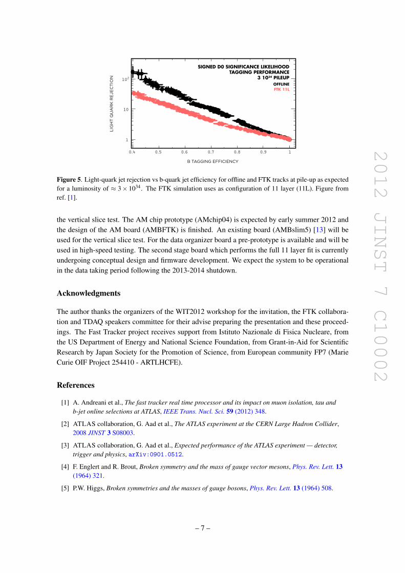
2012 JINST 7 C10002
04 05 06 07 08 09 1
LIG
HT
QU
AR
K R
EJE
CT
ION
B TAGGING EFFICIENCY
1
10
210
SIGNED D0 SIGNIFICANCE LIKELIHOODTAGGING PERFORMANCE
3 1034 PILEUPOFFLINEFTK 11L
Figure 5 Light-quark jet rejection vs b-quark jet efficiency for offline and FTK tracks at pile-up as expectedfor a luminosity of asymp 3times 1034 The FTK simulation uses as configuration of 11 layer (11L) Figure fromref [1]
the vertical slice test The AM chip prototype (AMchip04) is expected by early summer 2012 andthe design of the AM board (AMBFTK) is finished An existing board (AMBslim5) [13] will beused for the vertical slice test For the data organizer board a pre-prototype is available and will beused in high-speed testing The second stage board which performs the full 11 layer fit is currentlyundergoing conceptual design and firmware development We expect the system to be operationalin the data taking period following the 2013-2014 shutdown
Acknowledgments
The author thanks the organizers of the WIT2012 workshop for the invitation the FTK collabora-tion and TDAQ speakers committee for their advise preparing the presentation and these proceed-ings The Fast Tracker project receives support from Istituto Nazionale di Fisica Nucleare fromthe US Department of Energy and National Science Foundation from Grant-in-Aid for ScientificResearch by Japan Society for the Promotion of Science from European community FP7 (MarieCurie OIF Project 254410 - ARTLHCFE)
References
[1] A Andreani et al The fast tracker real time processor and its impact on muon isolation tau andb-jet online selections at ATLAS IEEE Trans Nucl Sci 59 (2012) 348
[2] ATLAS collaboration G Aad et al The ATLAS experiment at the CERN Large Hadron Collider2008 JINST 3 S08003
[3] ATLAS collaboration G Aad et al Expected performance of the ATLAS experiment mdash detectortrigger and physics arXiv09010512
[4] F Englert and R Brout Broken symmetry and the mass of gauge vector mesons Phys Rev Lett 13(1964) 321
[5] PW Higgs Broken symmetries and the masses of gauge bosons Phys Rev Lett 13 (1964) 508
ndash 7 ndash
2012 JINST 7 C10002
[6] G Guralnik C Hagen and T Kibble Global conservation laws and massless particles Phys RevLett 13 (1964) 585
[7] J Adelman et al The silicon vertex trigger upgrade at CDF Nucl Instrum Meth A 572 (2007) 361
[8] A Annovi et al A VLSI processor for fast track finding based on content addressable memoriesIEEE Trans Nucl Sci 53 (2006) 2428
[9] M DellrsquoOrso and L Ristori VLSI structures for track finding Nucl Instrum Meth A 278 (1989)436
[10] A Annovi et al A new variable-resolution associative memory for high energy physicsAdvancements in Nuclear Instrumentation Measurement Methods and their Applications (ANIMMA)2011 2nd International Conference on Digital Object Identifier ANIMMA (2011)
[11] A Annovi et al The EDRO board connected to the associative memory ldquobabyrdquo fasttrackerprocessor for the ATLAS experiment in 2nd International Conference on Technology andInstrumentation in Particle Physics Chicago IL USA 9ndash14 June 2011
[12] A Annovi and M Beretta A fast general-purpose clustering algorithm based on FPGAs forhigh-throughput data processing Nucl Instrum Meth A 617 (2010) 254 [arXiv09102572]
[13] A Annovi et al Associative memory design for the Fast Tracker Processor (FTK) at ATLAS IEEENucl Sci Symp Med Imag Conf (NSSMIC) (2011) 141
ndash 8 ndash
- The FTK system
-
- The ATLAS detector and trigger
-
- Technical design
-
- Overview
- Pattern recognition and track fitting
- Variable resolution patterns
-
- Physics with the FTK
-
- Simulated performance
-
- Conclusion
-