
PCSR – Sub-chapter 14.7 – Fault and Protection...
61
Title: PCSR – Sub-chapter 14.7 – Fault and Protection Schedule UKEPR-0002-149 Issue 03 Total number of pages: 61 Page No.: I / III Chapter Pilot: F. CERRU Name/Initials Date 26-11-2012 Approved for EDF by: A. MARECHAL Approved for AREVA by: G. CRAIG Name/Initials Date 26-11-2012 Name/Initials Date 26-11-2012 REVISION HISTORY Issue Description Date 00 First issue. 27-06-2009 01 Removal of RESTRICTED classification 11-06-2010 02 Consolidated Step 4 PCSR update: - Minor editorial changes - Update and addition of references - Consistency with UK classification approach - New section 4 added, “Adequacy of design to protect the plant against faults – ALARP discussion” added 29-03-2011 03 Consolidated PCSR update: - References listed under each numbered section or sub-section heading numbered [Ref-1], [Ref-2], [Ref-3], etc - Minor editorial changes - Update of Fault Schedule (Table 1) to reflect changes in classification, new PCC events, diversity analyses - Update of Appendix 1 to cover diverse means available to reach a long- term safe shutdown state 26-11-2012
Transcript of PCSR – Sub-chapter 14.7 – Fault and Protection...

Title: PCSR – Sub-chapter 14.7 – Fault and Protection
Schedule
UKEPR-0002-149 Issue 03
Total number of pages: 61 Page No.: I / III
Chapter Pilot: F. CERRU
Name/Initials
Date 26-11-2012
Approved for EDF by: A. MARECHAL Approved for AREVA by: G. CRAIG
Name/Initials Date 26-11-2012 Name/Initials
Date 26-11-2012
REVISION HISTORY
Issue Description Date
00 First issue. 27-06-2009
01 Removal of RESTRICTED classification 11-06-2010
02 Consolidated Step 4 PCSR update:
- Minor editorial changes
- Update and addition of references
- Consistency with UK classification approach
- New section 4 added, “Adequacy of design to protect the plant against faults – ALARP discussion” added
29-03-2011
03 Consolidated PCSR update: - References listed under each numbered section or sub-section heading
numbered [Ref-1], [Ref-2], [Ref-3], etc - Minor editorial changes - Update of Fault Schedule (Table 1) to reflect changes in classification,
new PCC events, diversity analyses - Update of Appendix 1 to cover diverse means available to reach a long-
term safe shutdown state
26-11-2012

Title: PCSR – Sub-chapter 14.7 – Fault and Protection Schedule
UKEPR-0002-149 Issue 03 Page No.:
II / III
Copyright © 2012
AREVA NP & EDF All Rights Reserved
This document has been prepared by or on behalf of AREVA NP and EDF SA in connection with their request for generic design assessment of the EPRTM design by the UK nuclear regulatory authorities. This document is the property of AREVA NP and EDF SA. Although due care has been taken in compiling the content of this document, neither AREVA NP, EDF SA nor any of their respective affiliates accept any reliability in respect to any errors, omissions or inaccuracies contained or referred to in it. All intellectual property rights in the content of this document are owned by AREVA NP, EDF SA, their respective affiliates and their respective licensors. You are permitted to download and print content from this document solely for your own internal purposes and/or personal use. The document content must not be copied or reproduced, used or otherwise dealt with for any other reason. You are not entitled to modify or redistribute the content of this document without the express written permission of AREVA NP and EDF SA. This document and any copies that have been made of it must be returned to AREVA NP or EDF SA on their request. Trade marks, logos and brand names used in this document are owned by AREVA NP, EDF SA, their respective affiliates or other licensors. No rights are granted to use any of them without the prior written permission of the owner.
Trade Mark EPRTM is an AREVA Trade Mark.
For information address:
AREVA NP SAS
Tour AREVA 92084 Paris La Défense Cedex
France
EDF Division Ingénierie Nucléaire
Centre National d'Equipement Nucléaire 165-173, avenue Pierre Brossolette
BP900 92542 Montrouge
France

Title: PCSR – Sub-chapter 14.7 – Fault and Protection Schedule
UKEPR-0002-149 Issue 03 Page No.:
III / III
TABLE OF CONTENTS
1. LIST OF INITIATING EVENTS
1.1. INTRODUCTION
1.2. NSSS DESIGN CONDITIONS (PCC EVENTS)
1.3. CORE MELT RISK REDUCTION CATEGORY (RRC-A EVENTS)
1.4. SEVERE ACCIDENTS (RRC-B EVENTS)
1.5. CONCLUSIONS
2. JUSTIFICATION OF THE COMPREHENSIVENESS OF FAULT PROTECTION
2.1. INTRODUCTION
2.2. DEFENCE IN DEPTH
2.3. DEFENCE LINES
3. PROTECTION SYSTEM I&C ARCHITECTURE
3.1. SAFETY FUNCTIONS
3.2. TYPES OF I&C FUNCTIONS
3.3. BASIS FOR THE DEFINITION OF AN I&C FUNCTION
3.4. SET OF I&C FUNCTIONS
3.5. RESET OF AUTOMATIC PROTECTION FUNCTIONS
3.6. PERMISSIVE SIGNALS
4. ADEQUACY OF DESIGN TO PROTECT THE PLANT AGAINST FAULTS – ALARP DISCUSSION
4.1. OVERVIEW OF PLANT PROTECTION
4.2. ANALYSIS OF FUNCTIONAL DIVERSITY
4.3. RADIOLOGICAL CONSEQUENCES
5. CONCLUSION
APPENDIX 1: DIVERSITY IN EMERGENCY OPERATING PROCEDURE
PRE-CONSTRUCTION SAFETY REPORT
CHAPTER 14: DESIGN BASIS ANALYSIS
SUB-CHAPTER : 14.7
PAGE : 1 / 58
Document ID.No. UKEPR-0002-149 Issue 03
SUB-CHAPTER 14.7 – FAULT AND PROTECTION SCHEDULE
This sub-chapter provides a summary of the fault and protection schedule for the UK EPR. It also gives an insight into the principles used to define the protection system set-points and those applied to modify or deactivate settings during changes in the reactor state. Sections 1 and 2 of this sub-chapter describe the fault and protection schedule, which illustrates two main features of the EPR design:
• the rationale and justification for the initiating events considered within the EPR design of protection and mitigation provisions due to their potentially unacceptable consequences (section 1);
• the different defence lines provided by the EPR design. Section 2 provides a justification of the comprehensiveness of the fault protection. The fault and protection schedule is given in Sub-chapter 14.7 – Table 1, which includes the initiating events and sequences, their frequencies, the classified safety systems that protect against them and the overall protection claims.
The fault schedule focuses on risks to the public; therefore, the fault schedule is based on the accidents described in Chapters 14 and 16. It also includes the analysis of the functional diversity of Sub-chapter 16.5.
Section 3 of the present sub-chapter provides information on the protection system settings and the principles applied to the deactivation or resetting of protection settings at low power states.
Section 4 of this sub-chapter provides information on the ALARP discussion regarding the adequacy of the UK EPR design to protect the plant against faults.
Section 5 of this sub-chapter provides an overall conclusion.
PRE-CONSTRUCTION SAFETY REPORT
CHAPTER 14: DESIGN BASIS ANALYSIS
SUB-CHAPTER : 14.7
PAGE : 2 / 58
Document ID.No. UKEPR-0002-149 Issue 03
1. LIST OF INITIATING EVENTS
1.1. INTRODUCTION
As an evolutionary reactor, the list of design basis faults considered within the EPR design basis is based on an initial list of design basis faults considered in early PWRs and additions arising from 30 years of operational feedback from international PWR fleet (studies, operations and interaction with safety authorities). Incorporation of experience feedback has provided the list of design basis faults considered with some additional robustness.
With regard to NSSS internal events (fault studies) a review of the initial basis for the fault schedule, and the main subsequent additions, are provided below.
1.2. NSSS DESIGN CONDITIONS (PCC EVENTS)
The initial approach to the PCC event list was an implementation of the principles set out by the committee N-18 of the American Standards Institute (ANSI N-18, 1973). Based on the defence in depth concept (three levels at that time), it introduced a categorisation of internal events based on a rough concept of “anticipated frequency” (based on the frequency expected in operation during plant life and from consideration of bounding hypothetical events).
FRATEC 01 (1979) [Ref-1] presents the FRAMATOME methodology for the definition of the initiating events list and the basis for its claim to provide an exhaustive list of faults. A comparison is also made to the application of the ANSI N-18 for US PWRs. After defining normal operating parameters, events which could cause them to vary outside of normal bounding values are identified, without trying to enumerate all the failures liable to adversely affect the nuclear steam supply system. These events are arranged into several families regarding the operating parameter they first affect. The more significant transient of each family with respect to challenges to the protection system and engineered safety feature is finally considered as a design basis event or accident.
It should be noted that the aim of PCC analysis is to define the design requirements for safety systems (protection systems for category 2 events and main safeguard systems for category 3 and 4 events), which are designed subject to specific stringent rules such as the Single Failure Criterion (SFC), and the assumption of bounding consequences. This is why the consideration of additional scenarios, that were not included in the initial list, has not led systematically to a change in the list, since the additional design provisions required to reach an acceptable level of consequences may not impact on the performance of main systems or the bounding consequences of the event.
For example, the interface Loss Of Coolant Accident (LOCA) did not challenge the initial design of the Safety Injection System (RIS [SIS]) based on “normal” LOCA, or the definition of bounding bypass consequences via Steam Generator Tube Rupture (SGTR), and consequently it was not added to the PCC list. Similarly when, with the introduction of the EPR, the definition of PCCs was extended to introduce the concept of a frequency range, no significant update of the list of PCC events analysis was required.

PRE-CONSTRUCTION SAFETY REPORT
CHAPTER 14: DESIGN BASIS ANALYSIS
SUB-CHAPTER : 14.7
PAGE : 3 / 58
Document ID.No. UKEPR-0002-149 Issue 03
The main subsequent additions to the FRATEC 01 approach were linked to changes in “design rules” (e.g. SFC, i.e. redundancy requirement at the component level) shifting to “safety analysis rules” (e.g. the requirement to assume an “aggravating failure” i.e. a redundancy requirement at the function level). Other examples were extension of the scenario duration through the operator action phase, and the introduction of additional event combinations involving Loss Of Offsite Power (LOOP).
Changes to the list of events were made related to the experience feedback and changes in system design options.
EPR specific options led to transients being added or excluded from the Design Basis Assessment (DBA) list that was used for in service French Nuclear Power Plants (NPP). The changes were in three main categories as follows:
1) Changes resulting from EPR constitutive options, such as:
• consideration of transients occurring in the different plant states led to PCC events for outages being introduced as design basis accidents (these were considered as beyond design basis accidents in previous French NPPs, and consequently analysed using less stringent rules);
• consideration of transients in auxiliary buildings, which led to the introduction of fuel pool transients, and transients in the effluent treatment building and the nuclear auxiliary building.
2) Changes due to design improvements in the EPR that had a direct impact on the list of design basis faults. An example was application of the break preclusion principle that led to the exclusion of 2-A LOCA from the PCC list. LOCA outside the containment was added to the DBA list to address the specific EPR design of the residual heat removal system function, which is provided by the safety injection system.
3) Changes due to the application of PSA early in the design process, which impacted on the justification of the list itself and on the way transients were arranged into the different PCC categories.
The use of PSA also impacted the list of RRC-A events considered, as mentioned below.
1.3. CORE-MELT RISK REDUCTION CATEGORY (RRC-A EVENTS)
The origin of the list of scenarios involving multiple failures (called RRC-A sequences in the EPR approach) was a French Safety Authority (ASN) request for consideration of design extension conditions representative of the total loss of main redundant systems (power supply, heat sink, SG feedwater, long term RIS [SIS] and reactor trip through Anticipated Transients Without Scram). PCC-4 criteria were imposed, but less stringent rules were accepted.
Later on, other scenarios were added at the request of the ASN, generally to illustrate the robustness of the defence in the EPR design (drainage of two SGs, initially corresponding to the SFC exception on main steam isolation valves; multiple SGTRs combined with Main Steam Line Break).
PRE-CONSTRUCTION SAFETY REPORT
CHAPTER 14: DESIGN BASIS ANALYSIS
SUB-CHAPTER : 14.7
PAGE : 4 / 58
Document ID.No. UKEPR-0002-149 Issue 03
Eventually, a connection was made with the probabilistic analysis, and with the periodic safety review process, by considering the main PSA level 1 sequences (see PCSR Sub-chapter 15.1). The concept of an RRC-A feature was introduced to give assurance that any system making a significant contribution to reduction in the core melt risk would be safety classified. The corresponding RRC-A list has thus become a self-evolving list, on the basis of the PSA revisions issued for the purpose of periodic safety reviews. The current status of this EPR list is a combination of the initial deterministic approach and of an early implementation of the probabilistic definition. The justification for the claim that the initiating event list used in the Level 1 PSA is comprehensive is presented in section 4 of Sub-chapter 15.1 (NSSS internal events).
1.4. SEVERE ACCIDENTS (RRC-B EVENTS)
The main characteristics of the EPR design approach to severe accidents are:
• postulated low-pressure core melt scenarios are defined to support the design of dedicated mitigation systems (RRC-B features list);
• “Practical elimination” (IAEA terminology) of large early releases is sought via design measures introduced to prevent direct containment heating, prompt criticality, steam and hydrogen explosions, containment bypass, fuel melting in the fuel building. Probabilistic calculations are may be used to justify design measures, but cannot be used in isolation, without corresponding design measure being introduced;
• specific stringent radiological criteria are associated with severe accidents consequences (limited need for sheltering or food restrictions, no need for emergency evacuation or permanent relocation in the vicinity of the site);
• global design effectiveness is confirmed via a level 2 PSA.
1.5. CONCLUSIONS
The list of PCC and RRC events considered in the EPR safety approach arises from two objectives: compliance with design rules (main protection and safeguard systems) and demonstration by safety analyses. An absolute claim on the exhaustiveness of the event lists considered is not possible. However the extensive review and development of the event lists over many years, and the recent use of PSA analyses, give confidence that this mainly deterministic design approach has captured the potential consequences of all significant initiating events that could occur.
PRE-CONSTRUCTION SAFETY REPORT
CHAPTER 14: DESIGN BASIS ANALYSIS
SUB-CHAPTER : 14.7
PAGE : 5 / 58
Document ID.No. UKEPR-0002-149 Issue 03
2. JUSTIFICATION OF THE COMPREHENSIVENESS OF FAULT PROTECTION
2.1. INTRODUCTION
In this section, the safety measures are identified and justified and their consistency with defence in depth concept is explained.
This chapter identifies the safety functional requirements applicable to the safety measures, the categorisation of the functions, and the classification of the systems, structures or components that contribute to the safety measure. A distinction is made between the lines of defence (first line consisting of preventive measures, main line consisting of protective measures and back up line consisting of back-up safety measures).
The safety measures described in this chapter are illustrated and detailed for each transient considered, in Sub-chapter 14.7 – Tables 1 and 2. For each initiating event, the fault schedule table gives the associated Plant Condition Category (PCC) or Risk Reduction Category (RRC) which bounds the resulting fault transient. It also identifies the PCSR section where the fault transient is considered, and, for each phase of the transient, the protection systems which perform the different required safety functions in the different defence lines.
2.2. DEFENCE IN DEPTH
A defence in depth concept, described in Sub-chapter 3.1, is applied at the design stage of the EPR. It leads to the implementation of five levels of defence in the engineered safety systems and components, as follows:
• level 1 is a combination of conservative design, quality assurance, high quality of fabrication and high level of surveillance activities (controls, monitoring) to prevent departures from normal plant operation;
• level 2 consists of the implementation of protection devices which make it possible to detect and correct the effects of deviations from normal operation or the effects of system failures. This defence level is aimed at ensuring the integrity of the fuel cladding and that of the primary cooling system so as to prevent anticipated operational occurrences from escalating to accident conditions;
• level 3 consist of safeguard systems, protection devices and operating procedures which make it possible to control the consequences of accidents that may occur so as to contain radioactive material and prevent occurrence of severe accidents;
• level 4 comprises measures aimed at preserving containment integrity and controlling severe accidents;
• level 5 includes, in the event of the failure of previous levels of defence, all measures for protecting the public against the effects of significant radiological discharges.

PRE-CONSTRUCTION SAFETY REPORT
CHAPTER 14: DESIGN BASIS ANALYSIS
SUB-CHAPTER : 14.7
PAGE : 6 / 58
Document ID.No. UKEPR-0002-149 Issue 03
Defence levels 2 and 3 are the only ones relevant to the lines of defence considered in the fault analysis. The preventive line of defence, as described below, is associated with level 2, while both the main and back-up lines of defence are associated with level 3. Note that it is not the purpose of the present sub-chapter to consider mitigation of severe accidents, radiological consequences or containment integrity (third barrier) issues.
2.3. DEFENCE LINES
2.3.1. First line of defence (prevention)
As defined in Sub-chapter 3.1, the second level of defence in depth involves detecting and correcting the effects of deviations from normal operation and the effects of systems failures. For that purpose the following are implemented in normal operation:
• core and RCP [RCS] automatic control functions;,
• monitoring of limiting conditions of operation (LCOs)
• automatic limitation functions for core and RCP [RCS] parameters.
The core and reactor control functions implement corrective action by activation of safety or non-safety systems whenever a perturbed situation is detected. For example, in the following actions could be implemented:
• opening of the Main Steam Bypass GCT [MSB] following a secondary pressure disturbance;
• triggering of the pressuriser spray system or the pressuriser heaters following a primary pressure disturbance;
• house-load operation following a loss of external power supply;
Additionally, LCO surveillance functions are implemented. An LCO surveillance function indicates or limits the variation of a process parameter such that the initial conditions of operation at the onset of a postulated initiating event are maintained as pre-supposed in the safety analyses. The LCO therefore bounds the operating range.
After exceeding the LCO, an alarm is displayed and automatic "passive" countermeasures that do not induce a power decrease are actuated (blockage of rod withdrawal, blockage of turbine load increase …). In case these passive countermeasures and the operator actions that follow the alarm display do not enable the restoration of the authorised operating condition, automatic "active" countermeasures are actuated (partial trip1
These countermeasures are actuated with a time delay to allow fast operating transients, such as power level steps and load rejections, to succeed.
, dilution stop, turbine load reduction …).
The analysis of design basis events does not take into account the beneficial aspects of functions ensured by systems involved in the preventive line (as they are generally not safety classified for that purpose).
1 Fast power reduction achieved by the dropping of a certain number of RCCAs and consistently adjusting the
turbine setpoint to reduce generator power on secondary side

PRE-CONSTRUCTION SAFETY REPORT
CHAPTER 14: DESIGN BASIS ANALYSIS
SUB-CHAPTER : 14.7
PAGE : 7 / 58
Document ID.No. UKEPR-0002-149 Issue 03
2.3.2. Main defence line (protection)
If the effect of systems comprising the preventive line is insufficient to control the deviation, and to return the core to safe conditions, a Reactor Trip (RT) is initiated by the Protection System (RPR [PS]) [Ref-1] and engineered safety systems may be actuated.
As defined in Sub-chapter 3.2, three physical states are defined corresponding to shutdown conditions to be attained in design basis events (PCC) and RRC-A sequences.
These make it possible to establish a hierarchy of the functions used to attain shutdown conditions:
• controlled state: the core is subcritical (a return to short-term criticality before operator actions leading simply to low nuclear power may acceptable on a case by case basis for a few events), heat removal is assured on a short-term basis, for example via steam generators, core water inventory is stable, radioactive discharges remain acceptable,
• safe shutdown state: the core is subcritical, residual heat is being removed on a long-term basis, radioactive discharges remain acceptable,
• final state: the core is subcritical, residual heat is being removed via primary or secondary systems, radioactive discharges remain acceptable.
Note that controlled and safe shutdown states are applicable to PCC conditions while the final state is used only in RRC-A analyses.
As a general rule for the design basis events, only the action of safety classified systems is assumed when demonstrating compliance with the PCC or RRC-A acceptance criteria as indicated in the criteria for Structure, Systems and Components classification provided in Sub-chapter 3.2.
In order to introduce redundancy within the line of protection, the RPR [PS] is divided into two sub-systems, A and B.
For reactor trip signals processed in the RPR [PS], the following design rules are applied:
• for any PCC-2 condition which initiates an RT, if the main initiation signal is processed in one sub-system, a second initiating signal is processed in the opposite sub-system2
• a sensor used for a main initiation signal for RT in a sub-system cannot be used by the second initiating signal in the opposite sub-system.
,
It may be necessary to inhibit an automatic signal to cancel actions initiated by the signal, for example to shut down a pump after automatic start-up by the RPR [PS]. This can be done by resetting or by using permissives.
2 With the exception of the partial loss of core coolant flow where no additional RT is required.

PRE-CONSTRUCTION SAFETY REPORT
CHAPTER 14: DESIGN BASIS ANALYSIS
SUB-CHAPTER : 14.7
PAGE : 8 / 58
Document ID.No. UKEPR-0002-149 Issue 03
A reset is an operator action to clear the memory of a stored automatic signal. In most cases, a reset does not imply any automatic action but only allows manual control of the system. For actuators that receive commands from the protection system, these commands have priority over post-accident manual actions. In this case, the reset of the protection system command is necessary to allow manual operation of the actuators in the control room in a post-accident situation on the safe path. In some specific cases, a permissive instead of a reset is used to inhibit signals coming from the protection system. A description of resets is given in section 3.5 of this sub-chapter.
Permissives can also be introduced to authorise the activation or deactivation of certain protection signals depending on the current status of the reactor. A permissive is a condition to be satisfied, based on the information given by a set of sensors. A permissive is produced as soon as its associated condition is satisfied.
There are two types of permissives, depending on whether the associated actions are performed automatically or manually:
• if the permissive is of the "automatic action" type, its validation (or invalidation) leads to automatic performance of the related actions,
• if the permissive is of the "manual action" type, its validation (or invalidation) does not lead to any automatic action, but allows the operator to perform the related actions manually.
A given permissive can be of the manual type with respect to activation, and of the automatic type with respect to deactivation, or vice versa.
Permissive signals have the same safety classification as the protective actions they inhibit. A description of permissives is given in section 3.6 of this sub-chapter.
2.3.3. Back-up line of defence
In accordance with the defence in depth principles and the HSE SAPs (notably FA.15), additional safety measures are introduced that aim to further reduce the risk of core melt, which could be caused typically by multiple failures such as total loss of a safeguard system.
To achieve such goal, the approach adopted is to ensure that a diverse means can be used as a back-up whenever the total failure of a safeguard system induces a significant risk of core melt. The event sequences that fall into this category are identified by Probabilistic Safety Assessment. Depending on the type of sequence, the diverse system may be another, already existing system, or an additional system specifically introduced to prevent the risk of core melt. For the additional systems, due to the low probability of the event sequences considered, it is acceptable to apply less stringent design requirements than for the normal safeguard systems and a safety classification consistent with the principles described in Sub-chapter 3.2 is adopted.
The deterministic analysis of the Risk Reduction Category A (RRC-A) event sequences provides the basis for the specification of the required characteristics and performance of the diverse systems.
Diversity can be provided between the trains of a redundant system or by another system, diverse from the system it has to back up. Both solutions are adopted for the EPR. Safety systems and functions have been designed applying functional diversity: the intention is to provide, whenever possible, a diverse system which can perform the desired function and bring the plant back to a safe condition in the highly unlikely event of all the redundant trains of a system becoming totally unavailable.

PRE-CONSTRUCTION SAFETY REPORT
CHAPTER 14: DESIGN BASIS ANALYSIS
SUB-CHAPTER : 14.7
PAGE : 9 / 58
Document ID.No. UKEPR-0002-149 Issue 03
For frequent events (PCC-2) for which no back-up line has been identified, arguments are given in Sub-chapter 14.7 – Table 1 for why this situation is still acceptable from a safety point of view.

PRE-CONSTRUCTION SAFETY REPORT
CHAPTER 14: DESIGN BASIS ANALYSIS
SUB-CHAPTER : 14.7
PAGE : 10 / 58
Document ID.No. UKEPR-0002-149 Issue 03
3. PROTECTION SYSTEM I&C ARCHITECTURE
This section describes the basic architecture of the I&C systems used to actuate the EPR control and protection functions, and explains the principles used to define protection system settings, and to modify or deactivate settings during changes in the reactor state.
3.1. SAFETY FUNCTIONS
To structure the Primary/Secondary (P/S) I&C functions, a hierarchy is used.
It is based on the objective of preventing or minimising the release of radioactivity to the environment during transients, by ensuring the integrity of the three barriers:
• the fuel cladding;
• the reactor coolant system;
• the containment.
The safety functions to be achieved to ensure a safe control of the plant can be divided into the five following basic safety functions or “control modes” [Ref-1].
• Reactivity control;
• Reactor heat removal;
• RCP [RCS] integrity;
• RCP [RCS] inventory control;
• Containment of radioactivity.
3.2. TYPES OF I&C FUNCTIONS
The I&C functions are divided into six hierarchical categories:
• Level 1 : Control I&C functions;
• Level 2 : Limiting Conditions of Operation (LCO) surveillance I&C functions;
• Level 3 : Limitations I&C functions;
• Level 4 : Protection I&C functions;
• Level 5 : Post Accident Management I&C functions;
• Level 6: RRC I&C functions.

PRE-CONSTRUCTION SAFETY REPORT
CHAPTER 14: DESIGN BASIS ANALYSIS
SUB-CHAPTER : 14.7
PAGE : 11 / 58
Document ID.No. UKEPR-0002-149 Issue 03
3.2.1. Control I&C functions
The control I&C functions are those functions, which act on controlled parameters in order to follow control setpoints in all plant conditions.
Control I&C functions are Non-Classified (NC)
3.2.2. LCO surveillance I&C functions
The LCO surveillance I&C functions are those functions which are implemented to initiate (manually or automatically) in cases of violation of LCO. The functions contribute to maintaining the initial conditions within the limits adopted in the safety analyses.
3.2.3. Limitation I&C functions
The limitation I&C functions are functions which are implemented to initiate corrective measures (manually or automatically) in case the operating point comes too close to the protection system thresholds (avoidance of protection action).
The main objective of these functions is to improve the plant availability by terminating abnormal transients at an early stage in order to avoid actuation of a protection action.
The beneficial effect of limitation functions is not taken into account in safety analyses, under the rules applied in accident analysis. However credit for their role can be taken in probabilistic studies of certain transients.
3.2.4. Protection I&C functions
The protection I&C functions are functions which are implemented to mitigate the consequences of a Postulated Initiating Event (PIE) automatically after its detection. They include automatic actuation of protection actions and safety-grade systems, and automatic control of these actions during the short term accident phase. This phase is considered to last for 30 minutes after the occurrence of the first significant alarm following detection of the PIE.
The short term phase is the time period where the protection actions must be automatic. The EPR design is that automation of the protection actions should enable the controlled state to be reached after an accident, and to be maintained as long as it is required for safety purposes. Therefore there is no reliance on operator action to bring the plant to a safe stable state, manual actions being required to transfer the plant from the controlled state to the safe shutdown state.
The above requirements ensure automation of protection functions in the short term post-accident phase, but do not mean that beneficial operator actions are precluded: beneficial manual actions either to anticipate automatic actions, or to improve the mitigation level, are desirable, and these are permitted when they are in accordance with emergency operating guidelines.
3.2.5. Post accident management I&C functions
The post-accident I&C functions are the functions required to bring the plant from the controlled state to the safe shutdown state and to maintain it.
In the safety analyses, a manual action from the main control room cannot be credited within the 30 minutes after the first significant information given to the operator.
PRE-CONSTRUCTION SAFETY REPORT
CHAPTER 14: DESIGN BASIS ANALYSIS
SUB-CHAPTER : 14.7
PAGE : 12 / 58
Document ID.No. UKEPR-0002-149 Issue 03
Thus, if actions to bring the plant to the safe shutdown have to be undertaken before 30 minutes, the required post-accident I&C functions must be automatic. Otherwise, manual post-accident functions are considered sufficient..
3.2.6. RRC I&C functions
The RRC I&C functions are those functions, which are implemented to mitigate the consequences of an RRC event (an RRC event could be either a PIE combined with a common cause failure or an event involving multiple coincident PIEs). The RRC I&C functions include either manual or automatic actuation of reactor trip and/or the safeguard systems, the control of these actions, or the simple detection of an accident which requires manual intervention from the operator more than 30 minutes after the first significant alarm.
3.3. BASIS FOR THE DEFINITION OF AN I&C FUNCTION
The concept of I&C functions is used to structure I&C tasks into small functional units such that each unit:
• gives a complete representation of a functional objective (safety objective or operational objective);
• can be classified according to its degree of safety importance;
• comprises the smallest entity form sensor to actuator to achieve its functional objective;
• is as far as possible independent from other units and therefore easily exchangeable.
The full set of I&C functions provides a modular functional structure for the I&C which forms the basis of the overall I&C architecture and enables process engineers to verify whether the postulated events are controlled and mitigated in the expected manner.
An I&C function must be as simple as possible.
It must rely on parameters as close as possible to:
• the physical phenomenon under control,
• a symptom-based approach.
An I&C function must rely on an event-based approach, when required.
An I&C function must be designed to avoid Non-unequivocally Safety Oriented (NUSO) I&C functions as far as possible. The NUSO definition is given in section 3.4.1

PRE-CONSTRUCTION SAFETY REPORT
CHAPTER 14: DESIGN BASIS ANALYSIS
SUB-CHAPTER : 14.7
PAGE : 13 / 58
Document ID.No. UKEPR-0002-149 Issue 03
3.4. SET OF I&C FUNCTIONS
3.4.1. NUSO functions
When two I&C functions, with the same classification, perform opposing actions within the same safety system, the one which has priority over the other one is called Non-unequivocally Safety Oriented (NUSO). All other I&C functions are called Unequivocally Safety Oriented (USO).
The faulty actuation of NUSO, during many events, significantly lessens or impairs the actual plant safety level, because it prevents from the action of an other I&C function which is needed to mitigate the accident.
Due to their potential negative impact on safety when spuriously actuated, the NUSO I&C functions shall be designed in a way to minimise the probability of spurious action.
3.4.2. Setpoints scales
Setpoints result from the hierarchical organisation of I&C functions described above.
The overall I&C design approach to ensure a high level of plant safety is based on:
• consideration of the channel accuracy,
• consideration of the response time of the I&C function,
• the threshold margin to ensure plant reliability in case of failure of the dedicated I&C function,
• application of the single failure criterion to I&C systems,
• priority requirements between different I&C functions.
In Sub-chapter 14.7 - Figures 1 and 2, examples of setpoint scales with the corresponding actions are shown.
3.5. RESET OF AUTOMATIC PROTECTION FUNCTIONS
3.5.1. Definition
A reset is an operator action to clear the memory of a stored automatic signal. It may be necessary to inhibit an automatic signal to cancel actions initiated by the signal. In most cases, a reset does not imply any automatic action but only allows a manual control of the system. When actuators receive commands from the protection system, these commands have priority over manual actions. In this case, the reset of the protection system command is necessary to allow manual operation of the actuators in the control room in a post-accident situation on the safe path.
As mentioned above, in general there is priority of automatic commands generated in PS over manual commands performed by the operator.
Note

PRE-CONSTRUCTION SAFETY REPORT
CHAPTER 14: DESIGN BASIS ANALYSIS
SUB-CHAPTER : 14.7
PAGE : 14 / 58
Document ID.No. UKEPR-0002-149 Issue 03
Most memories used are of two types:
• “reset priority” memories, for which the reset inhibits a signal if the conditions that govern signal activation are met at the time of actuation of the reset.
• “priority set” memories, for which the reset does not inhibit the signal, but inhibits storage of the signal if the conditions that determine signal activation are not met at the time of actuation of the reset.
3.5.2. Principles
Reset requirements with respect to protection system commands are defined in accordance with two basic hypotheses:
• the protection system issues non-reversible commands. This means that an initiated action is not ended even if the initiating conditions are no longer present.
• signals originated from the protection system are not stored as routine. Conditions for storage have to be defined individually for each signal.
3.5.3. Reset description
Resets (and associated memories) are analysed with respect to two types of initiating signals:
• Non-spurious commands
A reset must be configured only if the protection command is stored, since it must be possible to cancel the protection system command to return to normal operation once the required conditions are met. This reset will be of the non-priority type, except in special cases.
• Spurious commands.
There are two kinds of spurious commands: pulse-type and permanent: the approach for the first kind of command is the same as for non-spurious commands and permanent ones have a very low probability.
The concept of single failure is incorporated into the design of resets required on the safe path in a post-accident situation.
A 2 fold redundancy is chosen for resets that are configured for actions on the safe path in a post-accident situation. No redundancy is necessary for resets that are configured for actions not on the safe path in a post-accident situation (except in special cases).
In some specific cases, a permissive instead of a reset is used to inhibit signals coming from the protection system.
PRE-CONSTRUCTION SAFETY REPORT
CHAPTER 14: DESIGN BASIS ANALYSIS
SUB-CHAPTER : 14.7
PAGE : 15 / 58
Document ID.No. UKEPR-0002-149 Issue 03
3.6. PERMISSIVE SIGNALS
3.6.1. Definitions
Permissives are introduced to authorise the activation or deactivation of certain protection signals, according to the current operating status of the plant unit. Consequently, certain manual or automatic actions, related to the permissive, are authorised or not.
As these deactivations are detrimental to safety when the reactor is at power, they are authorised only in certain conditions, called permissives.
Each permissive is associated with a key. The permissive corresponds to the condition to be satisfied, and the key launches the actions authorised by the permissive. There are two types of permissives, depending on whether the key triggers automatic or manual actions. A given permissive can be of the manual type with respect to activation, and be automatic with respect to deactivation, or vice versa.
Permissives are identified by the letter P followed by a suffix. Permissives related to PS protection functions are for example: P12, P14, P15... Keys are identified by the word KEY (upper cases) followed by the same suffix as the associated permissive (e.g. KEY12 for P12).
3.6.2. Principles
It must be possible to perform the actions associated with the permissives in normal operating conditions and in post-accident phases. Therefore, validation of permissives and KEY actuation by the operator is possible from both the PICS (Process Information and Control System) and the SICS (Safety Information and Control System). The PICS and SICS are the systems which allow the display of information from the different I&C automation systems in the main control room.
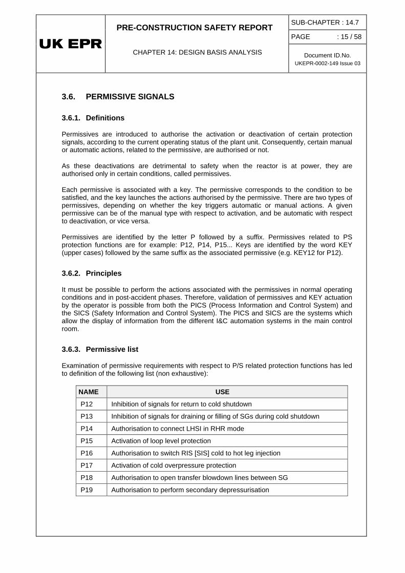
3.6.3. Permissive list
Examination of permissive requirements with respect to P/S related protection functions has led to definition of the following list (non exhaustive):
NAME USE
P12 Inhibition of signals for return to cold shutdown
P13 Inhibition of signals for draining or filling of SGs during cold shutdown
P14 Authorisation to connect LHSI in RHR mode
P15 Activation of loop level protection
P16 Authorisation to switch RIS [SIS] cold to hot leg injection
P17 Activation of cold overpressure protection
P18 Authorisation to open transfer blowdown lines between SG
P19 Authorisation to perform secondary depressurisation

PRE-CONSTRUCTION SAFETY REPORT
CHAPTER 14: DESIGN BASIS ANALYSIS
SUB-CHAPTER : 14.7
PAGE : 16 / 58
Document ID.No. UKEPR-0002-149 Issue 03
4. ADEQUACY OF DESIGN TO PROTECT THE PLANT AGAINST FAULTS – ALARP DISCUSSION
4.1. OVERVIEW OF PLANT PROTECTION
As described in section 2, several lines of defence are implemented in the design of the EPR. Deterministic protection aims at preventing any core damage and limits the radioactive release outside the containment. The main line of defence is designed on the basis of the fault studies in Sub-chapters 14.3 to 14.5. The overview of plant protection is then provided in the fault and protection schedule.
4.2. ANALYSIS OF FUNCTIONAL DIVERSITY
In order to ensure a high level of plant safety, the main line of defence is completed by a diverse line of protection which results from the RRC-A approach and the functional diversity analyses presented in Sub-chapters 16.1 and 16.5. These analyses ensure that two diverse lines of protection are sufficient to protect the plant for each frequent fault considered in the fault studies in Sub-chapters 14.3 and 14.4.
The results of these functional analyses are also provided in the fault and protection schedule.
4.3. RADIOLOGICAL CONSEQUENCES
The radiological consequences study presented in Sub-chapter 14.6 allows comparison with the SAP requirements. It demonstrates the adequacy of the design to protect the environment and people from radiation exposure consistent with the UK regulations for effective dose.
In addition to these studies, a Probabilistic Safety Assessment of the radiological releases and consequences allows an assessment of the plant protection by comparing the resulting doses and the frequency of releases (Sub-chapter 15.5). Demonstration, using a PSA model, that the nuclear safety risk from an EPR meets the BSO risk targets is considered to be an important element in the overall demonstration that the ALARP principle is met by the EPR (see Sub-chapter 17.4).

PRE-CONSTRUCTION SAFETY REPORT
CHAPTER 14: DESIGN BASIS ANALYSIS
SUB-CHAPTER : 14.7
PAGE : 17 / 58
Document ID.No. UKEPR-0002-149 Issue 03
5. CONCLUSION
The safety measures described in this sub-chapter are illustrated and detailed for each transient considered in the fault schedule. This fault schedule illustrates that the plant is protected by two diverse lines of protection for the most frequent events as detailed in the analyses of functional diversity provided in Sub-chapter 16.5. The efficiency of the plant to protect people and the environment from radiation exposure is highlighted in the deterministic radiological consequences analyses provided in Sub-chapter 14.6 and the probabilistic analyses provided in Sub-chapter 15.5. These two contributions form an important element in the demonstration that the ALARP principle is met by the UK EPR.

PRE-CONSTRUCTION SAFETY REPORT
CHAPTER 14: DESIGN BASIS ANALYSIS
SUB-CHAPTER : 14.7
PAGE : 18 / 58
Document ID.No. UKEPR-0002-149 Issue 03
SUB-CHAPTER 14.7 - TABLE 1: FAULT AND PROTECTION SCHEDULE TABLE: FAULTS AT FULL POWER (1/29)

PRE-CONSTRUCTION SAFETY REPORT
CHAPTER 14: DESIGN BASIS ANALYSIS
SUB-CHAPTER : 14.7
PAGE : 19 / 58
Document ID.No. UKEPR-0002-149 Issue 03
SUB-CHAPTER 14.7 - TABLE 1: FAULT AND PROTECTION SCHEDULE TABLE: FAULTS AT FULL POWER (2/29)
PRE-CONSTRUCTION SAFETY REPORT
CHAPTER 14: DESIGN BASIS ANALYSIS
SUB-CHAPTER : 14.7
PAGE : 20 / 58
Document ID.No. UKEPR-0002-149 Issue 03
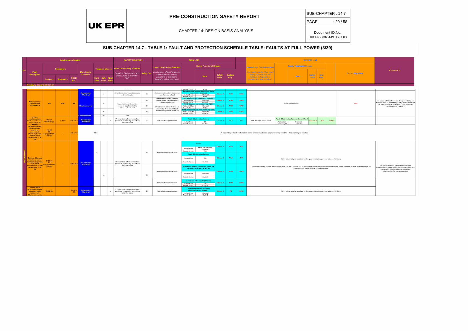
SUB-CHAPTER 14.7 - TABLE 1: FAULT AND PROTECTION SCHEDULE TABLE: FAULTS AT FULL POWER (3/29)
Category Frequency PCSRRef.
Cont. state
Safe state
Final state
Supporting studyItem
No.
Input to classification SAFETY FUNCTION MAIN LINE
Safety Functional Groups
System Req.
Safety class
CommentsFault
description
ReferencesMain Safety
Function
Transient phases Plant Level Safety Function
Based on EPR process and international practice for
PWR
Safety Cat.
Lower Level Safety Function
Combination of the Plant Level Safety Function and the conditions of operations
(normal, incident, accident)
Lower Level Safety Function
Combination of the Plant Level Safety Function and the conditions of operations
(normal, incident, accident)
DIVERSE LINE
Reactivity power distribution
Safety class
Syst Req.Item
Safety Functional Groups

PRE-CONSTRUCTION SAFETY REPORT
CHAPTER 14: DESIGN BASIS ANALYSIS
SUB-CHAPTER : 14.7
PAGE : 21 / 58
Document ID.No. UKEPR-0002-149 Issue 03
SUB-CHAPTER 14.7 - TABLE 1: FAULT AND PROTECTION SCHEDULE TABLE: FAULTS AT FULL POWER (4/29)

PRE-CONSTRUCTION SAFETY REPORT
CHAPTER 14: DESIGN BASIS ANALYSIS
SUB-CHAPTER : 14.7
PAGE : 22 / 58
Document ID.No. UKEPR-0002-149 Issue 03
SUB-CHAPTER 14.7 - TABLE 1: FAULT AND PROTECTION SCHEDULE TABLE: FAULTS AT FULL POWER (5/29)
C&I platform
Category Frequency PCSRRef.
Cont. state
Safe state
Final state
ActuationPZR LDNBRHL P
Actuation ATWS signal ( N-3 rod drop)
Front. Syst. CRDM Front. Syst. EBS
Actuation HL P
Front. Syst. CRDM
Actuation RT checkback Actuation SG P
Front. Syst. Turbine admission valves Front. Syst. MSIV
Actuation RT checkback Actuation RT checkback
Front. Syst. Full load MFW isolation valves Front. Syst. Full load MFW
isolation valves
Actuation SIS signal [PZR P] Actuation Manual
Front. Syst. MSRT Front. Syst. MSRT
Actuation SIS signal [PZR P ] Actuation ManualFront. Syst. MHSI Front. Syst. LHSI
Actuation SIS signal [PZR P ] Actuation Manual
Front. Syst. CVCS letdown valve Front. Syst. CVCS letdown valve
Actuation SG P Actuation ManualFront. Syst. MSRT Front. Syst. PDS
Actuation SG L Actuation Manual
Front. Syst. EFWS injection lines & storages Front. Syst. MHSI + LHSI
Activ. & Elec ManualFront. Syst. RCP
Actuation SG P Actuation PassiveFront. Syst. MSRT Front. Syst. MSSV
Actuation SIS signal [PZR P ]
Front. Syst. Containment isolation valves
Inadvertent opening of a pressurizer safety valve
PCC-310-4/(r.y)<f<10-
2/(r.y) 1.68.10-3 14.4.3
A
Essential component protection -Class 1
Shutdown and maintain core sub-criticality
SG safety valves opening
No need for diversity in case of CVCS malfunction - there is no direct release into the containment
SAS
SAS
SAS
SAS
PS
SAS
SAS
SAS
PS
PS
PS
PS
F1B
F1A
F1A
F2
F1B
F1B
F1B
F2
F1B
F1A
F1A
F1A
F1A
PS
PS
PS
SG Pressure Control - Overpressure protection
Isolation of CVCS letdown line (RCS isolation SI sequence)
F1AClass 1
PS
PS
Safety Functional Groups
Class 2
Isolation of CVCS letdown line
Negative reactivity fast insertion
Prevention of RCS drainage through auxiliary lines
Safety class
System Req.
Safety class
Syst Req.Item
A Water injection into the RCS
Class 1
Class 2
MSIV closure
Class 1
Class 1
Class 1
F1A
F1A
Sequences of primary bleed and feed detailed in case of Total Loss Of FeedWater
RRC-A
-
Secondary overpressure studies of Sub-chapter 3.4.1.5 illustrateEssential component protection
Heat removal by Low Head Emergency Core Cooling
System (ECCS)
Class 1
Containment building isolation
EFW actuation (1 train) + SG Blowdown Isolation
F1A PS
A diversified way to control the SG pressure could use the fact that the 4 MSRTs are
independent and that the PS is working or the manual opening of the MSRTsWater injection into the RCS
Covered by LOCA (BREAK SIZE UP TO 20 CM2) WITH FAILURE OF THE PARTIAL
COOL-DOWN SIGNAL (STATE A) - PCSR Sub-chapter 16.1.3.3.6
Covered by LOCA (BREAK SIZE UP TO 20 CM2) WITHOUT MHSI (STATE A) - PCSR
Sub-chapter 16.1.3.3.7
MHSI injection - Auto
SG Pressure Control - Cooling - Auto (MSRT)
SG Pressure Control - Cooling - Manu
LHSI in cold leg
Class 2
A RCS overcooling protection RCS overcooling protection
Excessive increase in steam flow study
SAS order in case of ATWS following PS failure
Class 1
Class 2
Full load MFW isolation (4SG)
A Negative reactivity fast insertion High concentrated and high pressure boron injection
ATWS SB provided in technical report about diversityClass 1 Class 2
Emergency boron injection into the core - diversified
F1A PSF2
Input to classification SAFETY FUNCTION
Item
Fault description
ReferencesMain Safety
Function
Transient phases
MAIN LINE
Safety Functional Groups
CommentsPlant Level Safety Function
Based on EPR process and international practice for
PWR
Safety Cat.
Lower Level Safety Function
Combination of the Plant Level Safety Function and the conditions of operations
(normal, incident, accident)
DIVERSE LINE
Lower Level Safety Function
Combination of the Plant Level Safety Function and the conditions of operations
(normal, incident, accident)
Question remains about SB-LOCA with break on EBS (capacity of the EBS tanks).
Prevent the failure or limit the consequences of failure of a
structure, system or component whose failure
could cause the impairment of
AOther
A
Decrease in RCS water inventory
14.3.14
Heat removal
Reactivity Control
x
Confinement x
x
x
x
x
x
x
x
Supporting study
x
x
Shutdown and maintain core sub-criticality
Prevention of uncontrolled positive reactivity insertion
into the core
Reactor trip - auto
Turbine Trip
Maintain sufficient Reactor Coolant System water
inventory for core cooling
Full load MFW isolation (4SG)
A
SG Pressure Control - Cooling
A
Prevention of RCS drainage through auxiliary lines
Heat removal by Steam Generators - Emergency
shutdown mode
Class 1
Class 1
Class 2
Class 2
Class 2
RCP stop - Manu
Opening of severe accident discharge line
SIS [RIS] in cold leg
F1A
CVCS malfunction
causing decrease in
reactor coolant inventory (state
A)
PCC-2f>10-2/(r.y) 7.10-3
Transfer heat from the reactor coolant to the ultimate heat
sink
Containment isolation stage 1 /
Class 1Limit the release of
radioactive material from the reactor containment
N/A This transient is fully covered by the SB LOCA in state A.
SAS
Reactor trip - auto
Class 2 F2

PRE-CONSTRUCTION SAFETY REPORT
CHAPTER 14: DESIGN BASIS ANALYSIS
SUB-CHAPTER : 14.7
PAGE : 23 / 58
Document ID.No. UKEPR-0002-149 Issue 03
SUB-CHAPTER 14.7 - TABLE 1: FAULT AND PROTECTION SCHEDULE TABLE: FAULTS AT FULL POWER (6/29)
C&I platform
Category Frequency PCSRRef.
Cont. state
Safe state
Final state
Supporting study
Decrease in RCS water inventory
CommentsPlant Level Safety Function
Based on EPR process and international practice for
PWR
Safety Cat.
Lower Level Safety Function
Combination of the Plant Level Safety Function and the conditions of operations
(normal, incident, accident)
DIVERSE LINE
Lower Level Safety Function
Combination of the Plant Level Safety Function and the conditions of operations
(normal, incident, accident)
Input to classification SAFETY FUNCTION
Item
Fault description
ReferencesMain Safety
Function
Transient phases
MAIN LINE
Safety Functional Groups
Safety class
System Req.
Safety class
Syst Req.Item
Safety Functional Groups
Actuation PZR PHL P Actuation ATWS signal
( N-3 rod drop)
Front. Syst. CRDM Front. Syst. EBS
Actuation HL P
Front. Syst. CRDM
Actuation RT checkback Actuation SG P
Front. Syst. Turbine admission valves Front. Syst. MSIV
Actuation RT checkback Actuation RT checkback
Front. Syst. Full load MFW isolation valves Front. Syst. Full load MFW
isolation valves
Actuation SIS signal [PZR P] Actuation ManualFront. Syst. MSRT Front. Syst. MSRT
Actuation SIS signal [PZR P ] Actuation ManualFront. Syst. MHSI Front. Syst. LHSI
Actuation SIS signal [PZR P ] Actuation Manual
Front. Syst. CVCS letdown valve Front. Syst. CVCS letdown valve
Actuation SG P Actuation ManualFront. Syst. MSRT Front. Syst. PDS
Actuation SG L Actuation Manual
Front. Syst. EFWS injection lines & storages Front. Syst. MHSI + LHSI
Activ. & Elec ManualFront. Syst. RCP
Actuation SG P Actuation PassiveFront. Syst. MSRT Front. Syst. MSSV
Actuation SIS signal [PZR P ] Actuation Manual
Front. Syst. Containment isolation valves Front. Syst. Containment
isolation valves
Loss of primary coolant outside the containment
PCC-310-4/(r.y)<f<10-
2/(r.y)- 14.4.11 Confinement x
Limitation of radioactive release outside containment
from radioactive auxiliary systems
A
SAS
SAS
SAS
F2
F1B
RCS overcooling protection
Negative reactivity fast insertion
PS
PS
PS
PS
F1A
SG Pressure Control - Cooling
Class 1
F1A
PS
F1B
F1A
F1B
Secondary overpressure studies of Sub-chapter 3.4.1.5 illustrate
SG safety valves opening
PS
PS
PS
PS
PS
F1A
F1A
F1A
F1A
Class 1 Prevention of RCS drainage through auxiliary lines
Isolation of CVCS letdown line
Opening of severe accident Class 2
Class 2
F1B
Sequences of primary bleed and feed detailed in case of Total Loss Of FeedWater
RRC-A
x
-Class 2
Covered by LOCA (BREAK SIZE UP TO 20 CM2) WITH FAILURE OF THE PARTIAL
COOL-DOWN SIGNAL (STATE A) - PCSR Sub-chapter 16.1.3.3.6
RCS overcooling protection
Class 1
Water injection into the RCS
Excessive increase in steam flow study
PCC-310-4/(r.y)<f<10-
2/(r.y)
Small break (not greater than
DN50) including a break
occuring on the Extra Boration
System injection line
(State A)
Prevent the failure or limit the consequences of failure of a
structure, system or xOther
x
Covered by LOCA (BREAK SIZE UP TO 20 CM2) WITHOUT MHSI (STATE A) - PCSR
Sub-chapter 16.1.3.3.7
SG Pressure Control - Cooling - Manu Class 2
F1BLHSI in cold leg
Class 2
SAS
SAS
Class 1 SAS order in case of ATWS following PS failure
MSIV closure
Class 1
Full load MFW isolation (4SG)
Class 2
F1A
SAS
PSPrevention of uncontrolled positive reactivity insertion
into the corex
Containment isolation stage 2 is not considered since the containment pressure
does not increase sufficiently
Due to the numerous events possible, the fault schedule does not present them. The leaks are terminated after detection by alarms in Fuel Building or Nuclear Auxiliary Buildings. The operator isolates the corresponding pipes from the Main Control Room.
Class 1
Isolation of CVCS letdown line (RCS isolation SI sequence)
Class 1
Heat removal by Low Head Emergency Core Cooling
System (ECCS)
Turbine Trip
Class 1
Negative reactivity fast insertion
Reactor trip - auto
Class 1Shutdown and maintain core sub-criticality
A diversified way to control the SG pressure could use the fact that the 4 MSRTs are
independent and that the PS is working or the manual opening of the MSRTs
Emergency boron injection into the core - diversified
Class 2High concentrated and high pressure boron injection ATWS cover Question remains about SB-LOCA with
break on EBS (capacity of the EBS tanks).
A Full load MFW isolation (4SG)
Water injection into the RCS
SG Pressure Control - Cooling - Auto (MSRT)
MHSI injection - Auto
F1A
Class 1 F1A
Heat removal
A
6.10-4
A
Essential component protection
Prevention of RCS drainage through auxiliary lines
Transfer heat from the reactor coolant to the ultimate heat
sinkAx
Reactivity Control
14.4.5
x
x
x
F2
F1B
Essential component protection
Class 1
SIS [RIS] in cold leg
x A
Maintain sufficient Reactor Coolant System water
inventory for core cooling
A
x
Class 2
RCP stop - Manu
SG Pressure Control -
EFW actuation (1 train) + SG Heat removal by Steam Generators - Emergency
shutdown mode
Class 1 F1A
F1AConfinement x Containment building isolation
Containment isolation
Class 2Limit the release of
radioactive material from the reactor containment
A Containment building isolation
Containment isolation stage 1 /
SAS
SAS
-
Reactor trip - auto
Class 2 F2 SAS
PSF2
Shutdown and maintain core sub-criticality Ax

PRE-CONSTRUCTION SAFETY REPORT
CHAPTER 14: DESIGN BASIS ANALYSIS
SUB-CHAPTER : 14.7
PAGE : 24 / 58
Document ID.No. UKEPR-0002-149 Issue 03
SUB-CHAPTER 14.7 - TABLE 1: FAULT AND PROTECTION SCHEDULE TABLE: FAULTS AT FULL POWER (7/29)
C&I platform
Category Frequency PCSRRef.
Cont. state
Safe state
Final state
Supporting study
Decrease in RCS water inventory
CommentsPlant Level Safety Function
Based on EPR process and international practice for
PWR
Safety Cat.
Lower Level Safety Function
Combination of the Plant Level Safety Function and the conditions of operations
(normal, incident, accident)
DIVERSE LINE
Lower Level Safety Function
Combination of the Plant Level Safety Function and the conditions of operations
(normal, incident, accident)
Input to classification SAFETY FUNCTION
Item
Fault description
ReferencesMain Safety
Function
Transient phases
MAIN LINE
Safety Functional Groups
Safety class
System Req.
Safety class
Syst Req.Item
Safety Functional Groups
Actuation PZR P
HL PFront. Syst. CRDM
Actuation RT checkback
Front. Syst. Turbine admission valves
Actuation RT checkback
Front. Syst. Full load MFW isolation valves
Actuation SIS signal [PZR P]
Front. Syst. MSRT
Actuation SIS signal [PZR P ]Front. Syst. MHSI
Actuation PassiveFront. Syst. IRWST systems
Actuation PassiveFront. Syst. IRWST systems
Actuation SIS signal [PZR P ]Front. Syst. LHSI
Actuation PassiveFront. Syst. Accumulators
Actuation SIS signal [PZR P ]
Front. Syst. CVCS letdown valve
Actuation SG PFront. Syst. MSRT
Actuation SG L
Front. Syst. EFWS injection lines & storages
Actuation SG PFront. Syst. MSRT
Actuation DP over RCP + SIS signal
Front. Syst. RCP
Actuation SIS [PZR P]Passive
Front. Syst. Containment isolation valves
Actuation SIS signal [PZR P ]
Front. Syst. Containment isolation valves
PS
PS
PS
PS
PS
PS
PS
PS
PS
PS
PS
PS
PS
PS
PS
N/A - diversity is applied to frequent initiating event above 10-3/r.y
F1A
F1A
F1A
F1A
F1A
F1A
F1A
F1A
F1A
F1A
F1A
F1A
F1A
Class 1
Class 1
Containment isolation stage 2
A
AHeat removal by Steam Generators - Emergency
shutdown mode
RCP stop - AutoEssential component protection
EFW actuation (1 train) + SG Blowdown Isolation
Maintain sufficient Reactor Coolant System water
inventory for core cooling
Water injection into the RCSA
Prevent the failure or limit the consequences of failure of a
structure, system or component whose failure
could cause the impairment of a safety function
x
Limit the release of radioactive material from the
reactor containment
Shutdown and maintain core sub-criticality
Turbine Trip
x
Negative reactivity fast insertion
Reactivity Control
x
Class 1
Class 1
Class 1
Transfer heat from the reactor coolant to the ultimate heat
sink
Prevention of RCS drainage through auxiliary lines
SG Pressure Control - Cooling
A
Class 1
Class 1
Class 1
Class 1
Prevention of uncontrolled positive reactivity insertion
into the core Full load MFW isolation (4SG)A
F1A
PS
RCS overcooling protection
Isolation of CVCS letdown line (RCS isolation SI sequence)
Accumulators injection
SG Pressure Control - Cooling - Auto (MSRT)
IRWST borated water storage, collect, filtration
LHSI injection in cold leg - Auto
MHSI injection - Auto
IRWST cooling
Other
Class 1
F1A
F1AClass 1
A
Reactor trip - auto
Confinement
x
x
Heat removal
x
x
Intermediate and large break LOCA (up to the surge linebreak, in states A and
B)
PCC-410-6/(r.y)<f<10-
4/(r.y)
6.10-4
(20-45cm²)
1.6.10-5
(45-180cm²)
1.3.10-6
(180-830cm²)
14.5.6
In case of IB/LB LOCA, the Safety Injection plays a role in reactivity control by providing borated water. Depending on the size of the
break, the LHSI and accumulators will empty more or less rapidly
x
Containment isolation stage 1 / RCPB isolation
x
A Containment building isolation
Class 1
Class 1
Class 1
Class 1
Class 1
SG Pressure Control - Overpressure protection

PRE-CONSTRUCTION SAFETY REPORT
CHAPTER 14: DESIGN BASIS ANALYSIS
SUB-CHAPTER : 14.7
PAGE : 25 / 58
Document ID.No. UKEPR-0002-149 Issue 03
SUB-CHAPTER 14.7 - TABLE 1: FAULT AND PROTECTION SCHEDULE TABLE: FAULTS AT FULL POWER (8/29)
C&I platform
Category Frequency PCSRRef.
Cont. state
Safe state
Final state
Supporting study
Decrease in RCS water inventory
CommentsPlant Level Safety Function
Based on EPR process and international practice for
PWR
Safety Cat.
Lower Level Safety Function
Combination of the Plant Level Safety Function and the conditions of operations
(normal, incident, accident)
DIVERSE LINE
Lower Level Safety Function
Combination of the Plant Level Safety Function and the conditions of operations
(normal, incident, accident)
Input to classification SAFETY FUNCTION
Item
Fault description
ReferencesMain Safety
Function
Transient phases
MAIN LINE
Safety Functional Groups
Safety class
System Req.
Safety class
Syst Req.Item
Safety Functional Groups
Actuation ManualFront. Syst. EBS
Actuation ManualFront. Syst. LHSI
Actuation ManualFront. Syst. MSRT
Actuation ManualFront. Syst. MHSI
Actuation Manual
Front. Syst. MHSI
Activ. & Elec ManualFront. Syst. RHRS
Confinement x N/A B
Actuation PZR PHL P
Front. Syst. CRDM
Actuation RT checkback
Front. Syst. Turbine admission valves
Actuation RT checkback
Front. Syst. Full load MFW isolation valves
Actuation ManualFront. Syst. MSRT
Actuation SIS signal [PZR P ]Front. Syst. MHSI
Actuation SIS signal [PZR P ]
Front. Syst. CVCS letdown valve
Actuation SG PFront. Syst. MSRT
Activ. & Elec ManualFront. Syst. RHRS
Actuation SIS signal [PZR P]Front. Syst. RHRS
Actuation PassiveFront. Syst. Accumulators
Actuation SIS signal [PZR P]Front. Syst. LHSI
Actuation PassiveFront. Syst. IRWST systems
Actuation SG L
Front. Syst. EFWS injection lines & storages
Actuation SG PFront. Syst. MSRT
Actuation DP over RCP + SIS signal
Front. Syst. RCP
Actuation SIS signal [PZR P ]
Front. Syst. Containment isolation valves
PS
PS
PS
PS
PS
PS
PS
PS
SAS
PS
SAS
SAS
SAS
SAS
SAS
SAS
PS
F1A
F1A
F1A
F1B
F1A
F1B
F1A
F1A
F1B
F1A
F1A
F1A
F1B
F1B
F1B
x B
F1A
F1A
F1A
LOCA up to 20 cm2 with loss of
partial cooldown signal
(at power)
Limit the release of radioactive material from the
reactor containmentB Containment building isolation
Prevent the failure or limit the consequences of failure of a
structure, system or component whose failure
could cause the impairment of a safety function
The EOP followed by the operator is similar to the one presented for PCC event in such
case
x
N/A - diversity is applied to frequent initiating event above 10-3/r.y
Containment isolation stage 1 /
EFW actuation (1 train) + SG
B Essential component protection
Class 1
RCP stop - Auto
SG Pressure Control - Overpressure protection
x
Emergency Operating Procedure All N/A All
Reactivity Control x
MHSI stop (1 train) is indicated combinated to RHRS actuation since it is one of the
condition to connect RHRS in such case.
LHSI injection in HL is only used in case of LB LOCA.
Class 2
Class 2
Water injection into the RCS
Heat removal by Steam Generators - Emergency
shutdown mode
LHSI injection in HL
Compensation for shutdown moderator effect
Emergency boron injection into the core - Manual
MHSI injection on large miniflow
See Appendix A
B
B
x
Maintain sufficient Reactor Coolant System water
inventory for core cooling
Shutdown and maintain core sub-criticality
MHSI stop (1 train)
Heat removal
x
xLHSI switch to RHR mode (1 train)
Heat removal in shutdown mode by Residual Heat
Removal system (RHRS)
Bx
RRC-A - 16.1.3.6
Reactivity Control
Heat removal
Other
Confinement
x Shutdown and maintain core sub-criticality B
Transfer heat from the reactor coolant to the ultimate heat
sink
B
B
Negative reactivity fast insertion
Reactor trip - auto
Class 1
Class 2
SG Pressure Control - Cooling
Containement isolation are already effective due to automatic actuation. In case of such automatic actuation failed, the operator can perform the containment isolation
F1B
F1B
F1B
Class 2
x
Class 1
Class 1
Class 1
xPrevention of uncontrolled positive reactivity insertion
into the coreB
x
Full load MFW isolation (4SG)RCS overcooling protection
Turbine Trip
x
Isolation of CVCS Low Pressure letdown line (RCS isolation SI
sequence)
Class 1
Class 1
Class 1
Class 2
MHSI injection - AutoClass 1
SG Pressure Control - Cooling
Class 1
Maintain sufficient Reactor Coolant System water
inventory for core cooling
B
B
x
x
PS
PS
SAS
Class 1 F1A PS
PS
x
Class 1
Class 1
x
IRWST borated water storage, collect, filtration
Heat removal in shutdown mode by Residual Heat
Removal system (RHRS)
LHSI switch to RHR mode (1 train)x
xIRWST cooling
Transfer heat from the reactor coolant to the ultimate heat
sink
x
xAccumulators injectionB
Heat removal by Steam Generators - Emergency
shutdown mode
Heat removal by Steam Generators - Emergency
shutdown mode
SG Pressure Control - Cooling
LHSI injection in CLClass 2
Class 2
Class 2
Class 2
Prevention of RCS drainage through auxiliary lines
Water injection into the RCS

PRE-CONSTRUCTION SAFETY REPORT
CHAPTER 14: DESIGN BASIS ANALYSIS
SUB-CHAPTER : 14.7
PAGE : 26 / 58
Document ID.No. UKEPR-0002-149 Issue 03
SUB-CHAPTER 14.7 - TABLE 1: FAULT AND PROTECTION SCHEDULE TABLE: FAULTS AT FULL POWER (9/29)
C&I platform
Category Frequency PCSRRef.
Cont. state
Safe state
Final state
Supporting study
Decrease in RCS water inventory
CommentsPlant Level Safety Function
Based on EPR process and international practice for
PWR
Safety Cat.
Lower Level Safety Function
Combination of the Plant Level Safety Function and the conditions of operations
(normal, incident, accident)
DIVERSE LINE
Lower Level Safety Function
Combination of the Plant Level Safety Function and the conditions of operations
(normal, incident, accident)
Input to classification SAFETY FUNCTION
Item
Fault description
ReferencesMain Safety
Function
Transient phases
MAIN LINE
Safety Functional Groups
Safety class
System Req.
Safety class
Syst Req.Item
Safety Functional Groups
Actuation PZR PHL P
Front. Syst. CRDM
Actuation RT checkback
Front. Syst. Turbine admission valves
Actuation RT checkback
Front. Syst. Full load MFW isolation valves
Actuation SIS signal [PZR P ]Front. Syst. MSRT
Actuation ManualFront. Syst. MSRT
Actuation SIS signal [PZR P ]Front. Syst. LHSI
Actuation SIS signal [PZR P ]
Front. Syst. CVCS letdown valve
Actuation SG PFront. Syst. MSRT
Activ. & Elec ManualFront. Syst. RHRS
Actuation SIS signal [PZR P]Front. Syst. RHRS
Actuation PassiveFront. Syst. Accumulators
Actuation SIS signal [PZR P]Front. Syst. LHSI
Actuation PassiveFront. Syst. IRWST systems
Actuation SG L
Front. Syst. EFWS injection lines & storages
Actuation SG PFront. Syst. MSRT
Actuation DP over RCP + SIS signal
Front. Syst. RCP
Actuation SIS signal [PZR P ]
Front. Syst. Containment isolation valves
PS
PS
PS
PS
SAS
PS
PS
PS
PS
PS
PS
PS
PS
PS
SAS
PS
PS
F1A
F1A
F1A
F1A
F1A
F1B
F1A
F1A
F1A
F1B
F1A
F1B
F1A
F1A
F1A
F1A
F1A
LOCA up to 20 cm2 without
MHSI (at power)
SG Pressure Control - CoolingClass 2x
Limit the release of radioactive material from the
reactor containmentB Containment building isolation
B Negative reactivity fast insertion
Reactor trip - auto
RRC-A - 16.1.3.7
Reactivity Control
x Shutdown and maintain core sub-criticality
Containment isolation stage 1 /
N/A - diversity is applied to frequent initiating event above 10-3/r.yThe EOP followed by the operator is similar to the one presented for PCC event in such
case without MHSI isolation
B RCS overcooling protection
Turbine Trip
Class 1
Full load MFW isolation (4SG)
Class 1
xPrevention of uncontrolled positive reactivity insertion
into the corex
Heat removal
LHSI injection in CLMaintain sufficient Reactor
Coolant System water inventory for core cooling
Water injection into the RCS
SG Pressure Control - Cooling
B Prevention of RCS drainage through auxiliary lines
Isolation of CVCS letdown line (RCS isolation SI sequence)
B
x
x
x
x
Prevent the failure or limit the consequences of failure of a
structure, system or component whose failure
could cause the impairment of a safety function
x
Other x Essential component protection
SG Pressure Control - Overpressure protection
RCP stop - Auto
Heat removal by Steam Generators - Emergency
shutdown mode
LHSI switch to RHR mode (1 train)
Class 1
Class 1
Class 2
Class 1
Class 1
Class 1
Class 1
Class 1
Confinement x
x
x
Class 1
Class 1
Class 1
Class 1
EFW actuation (1 train) + SG
B
SG Pressure Control - Cooling
Class 2
Accumulators injection
Class 1
IRWST borated water storage, collect, filtration
Transfer heat from the reactor coolant to the ultimate heat
sink
LHSI injection in CL
IRWST cooling
x
x
x
Heat removal in shutdown mode by Residual Heat
Removal system (RHRS)
Heat removal by Steam Generators - Emergency
shutdown mode
B

PRE-CONSTRUCTION SAFETY REPORT
CHAPTER 14: DESIGN BASIS ANALYSIS
SUB-CHAPTER : 14.7
PAGE : 27 / 58
Document ID.No. UKEPR-0002-149 Issue 03
SUB-CHAPTER 14.7 - TABLE 1: FAULT AND PROTECTION SCHEDULE TABLE: FAULTS AT FULL POWER (10/29)
C&I platform
Category Frequency PCSRRef.
Cont. state
Safe state
Final state
Supporting study
Decrease in RCS water inventory
CommentsPlant Level Safety Function
Based on EPR process and international practice for
PWR
Safety Cat.
Lower Level Safety Function
Combination of the Plant Level Safety Function and the conditions of operations
(normal, incident, accident)
DIVERSE LINE
Lower Level Safety Function
Combination of the Plant Level Safety Function and the conditions of operations
(normal, incident, accident)
Input to classification SAFETY FUNCTION
Item
Fault description
ReferencesMain Safety
Function
Transient phases
MAIN LINE
Safety Functional Groups
Safety class
System Req.
Safety class
Syst Req.Item
Safety Functional Groups
Actuation PZR PHL P
Front. Syst. CRDM
Actuation RT checkback
Front. Syst. Turbine admission valves
Actuation RT checkback
Front. Syst. Full load MFW isolation valves
Actuation ManualFront. Syst. MSRT
Actuation SIS signal [PZR P ]Front. Syst. MHSI
Actuation SIS signal [PZR P ]
Front. Syst. CVCS letdown valve
Actuation SG PFront. Syst. MSRT
Activ. & Elec ManualFront. Syst. RHRS
Actuation SIS signal [PZR P]Front. Syst. RHRS
Actuation PassiveFront. Syst. Accumulators
Actuation SIS signal [PZR P]Front. Syst. LHSI
Actuation PassiveFront. Syst. IRWST systems
Actuation SG L
Front. Syst. EFWS injection lines & storages
Actuation SG PFront. Syst. MSRT
Actuation DP over RCP + SIS signal
Front. Syst. RCP
Actuation SIS signal [PZR P ]
Front. Syst. Containment isolation valves
PS
PS
PS
PS
PS
PS
SAS
PS
PS
PS
SAS
PS
PS
F1A
F1A
F1A
F1A
F1A
F1B
F1A
F1B
F1A
F1A
F1A
F1A
RCP stop - Auto
B Containment building isolation
Containment isolation stage 1 / RCPB isolation
Class 1
B Essential component protection
SG Pressure Control - Overpressure protection
LOCA up to 20 cm2 without
LHSI (at power)
xLimit the release of
radioactive material from the reactor containment
x
Prevent the failure or limit the consequences of failure of a
structure, system or component whose failure
could cause the impairment of a safety function
B
SG Pressure Control - Cooling
B
Class 1
EFW actuation (1 train) + SG
Class 1
Class 2
IRWST borated water storage, collect, filtration
Accumulators injection
LHSI injection in CL
x
Transfer heat from the reactor coolant to the ultimate heat
sink
x
x
Isolation of CVCS letdown line (RCS isolation SI sequence)
x Prevention of RCS drainage through auxiliary lines
MHSI injection - AutoClass 1
B
x
Maintain sufficient Reactor Coolant System water
inventory for core cooling
Water injection into the RCS
SG Pressure Control - Cooling
Class 1
x
x
Full load MFW isolation (4SG)
Class 1
In such case, due to the loss of LHSI, the cooling is made by the CHRS [EVU] with a
cooling of the IRWST. The MHSI are switched to large min flow lines. The cooling is then ensured by a circulation between the cooled IRWST, the MHSI injection and the
break.
xPrevention of uncontrolled positive reactivity insertion
into the coreB RCS overcooling protection
Turbine Trip
Class 1
B Negative reactivity fast insertion
Reactor trip - auto
x Shutdown and maintain core sub-criticality
RRC-A - 16.1.3.8
Reactivity Control
Heat removal
Confinement
Other
N/A - diversity is applied to frequent initiating event above 10-3/r.y
Class 1 F1A PS
Class 1
Class 1 F1A
Class 1 F1A
PS
Class 2 F1B PS
Class 1
x
x
x
x
IRWST cooling
Heat removal by Steam Generators - Emergency
shutdown mode
Class 1
LHSI switch to RHR mode (1 train)
Class 2
Heat removal by Steam Generators - Emergency
shutdown mode
Heat removal in shutdown mode by Residual Heat
Removal system (RHRS)

PRE-CONSTRUCTION SAFETY REPORT
CHAPTER 14: DESIGN BASIS ANALYSIS
SUB-CHAPTER : 14.7
PAGE : 28 / 58
Document ID.No. UKEPR-0002-149 Issue 03
SUB-CHAPTER 14.7 - TABLE 1: FAULT AND PROTECTION SCHEDULE TABLE: FAULTS AT FULL POWER (11/29)
C&I platform
Category Frequency PCSRRef.
Cont. state
Safe state
Final state
Supporting study
Decrease in RCS water inventory
CommentsPlant Level Safety Function
Based on EPR process and international practice for
PWR
Safety Cat.
Lower Level Safety Function
Combination of the Plant Level Safety Function and the conditions of operations
(normal, incident, accident)
DIVERSE LINE
Lower Level Safety Function
Combination of the Plant Level Safety Function and the conditions of operations
(normal, incident, accident)
Input to classification SAFETY FUNCTION
Item
Fault description
ReferencesMain Safety
Function
Transient phases
MAIN LINE
Safety Functional Groups
Safety class
System Req.
Safety class
Syst Req.Item
Safety Functional Groups
Actuation SIS signal [RCS L]SIS signal [ΔPsat ] Actuation Diversified RCS L
Front. Syst. MHSI Front. Syst. MHSI
Actuation SIS signal [RCS L]SIS signal [ΔPsat ] Actuation Diversified RCS L
Front. Syst. CVCS letdown valve Front. Syst. CVCS letdown valve
Actuation SIS signal [ΔPsat ] Actuation ManualFront. Syst. MHSI Front. Syst. MHSI
Actuation SIS signal [ΔPsat ] Actuation Manual
Front. Syst. CVCS letdown valve Front. Syst. CVCS letdown valve
Actuation DP over RCP + SIS signal Activ. & Elec Manual
Front. Syst. RCP Front. Syst. RCP
Actuation SIS signal [ΔPsat ] Actuation Manual
Front. Syst. Containment isolation valves Front. Syst. Containment
isolation valves
Small break LOCA (not
greater than DN 50) including a
break in the EBS injection
line (states C1, C2)
PCC-410-6/(r.y)<f<10-
4/(r.y)- 14.5.7
Actuation SIS signal [RCS L]SIS signal [ΔPsat ]
Front. Syst. MHSI
Actuation SIS signal [RCS L]SIS signal [ΔPsat ]
Front. Syst. CVCS letdown valve
Actuation ManualFront. Syst. CHRS
Actuation SIS signal [RCS L]SIS signal [ΔPsat ]
Front. Syst. Containment isolation valves
Actuation RCS L
Front. Syst. CVCS letdown valve
PS
PS
PS
PS
F1B
F1B
F2
Prevention of RCS drainage through auxiliary lines
F1A
F1A
F1A
F1A
This transient is similar to the SB LOCA in state B, in terms of systems actuation. One MHSI pump is sufficient to manage the sequence.
Containment isolation
Only the main features of the mitigation are presented. The heat removal is ensured
thanks ot the other RHRS trains. Reactivity control is not impaired.
There is no specific EOP since the transient occur in shutdown state.
Containment isolation stage 1 /
F1A
F1B
Isolation of CVCS letdown line
N/A
Confinement
N/A - diversity is applied to frequent initiating event above 10-3/r.y
Class 1
N/A - diversity is applied to frequent initiating event above 10-3/r.y
Water injection into the RCS
F1A
F2 PS
PS
PS
PS
Only the main features of the mitigation are presented. The heat removal is ensured
thanks ot the RHRS trains. Reactivity control is not impaired.
There is no specific EOP since the transient occur in shutdown state.
SHU
TDO
WN
MO
DE
Isolation of CVCS letdown line
Class 3Heat removal x B Prevention of RCS drainage through auxiliary lines
PCC-410-6/(r.y)<f<10-
4/(r.y)
A Containment building isolation
x
Confinement x
A
Isolable Safety Injection
System break (≤ DN 250) in
residual heat removal mode (states C, D)
Maintain sufficient Reactor Coolant System water
inventory for core cooling16.1.3.9-RRC-A
Uncontrolled RCS level drop
without SI signal from PS (in shutdown
state)
Limit the release of radioactive material from the
reactor containment
14.5.14-
A Prevention of RCS drainage through auxiliary lines
Isolation of CVCS letdown line (RCS isolation SI sequence)
Class 1
x
RCP stop - Auto
Other
Small break (not greater than DN 50) including a break occurring
on the Extra Boration System
injection line (state B)
PCC310-4/(r.y)<f<10-
2/(r.y)- 14.4.5
Class 1Containment building isolation
Containment isolation stage 1 /
A
Heat removal
Heat removal
Water injection into the RCS
x
MHSI injection - Auto
Maintain sufficient Reactor Coolant System water
inventory for core cooling
MHSI injection - auto
Class 1 Water injection into the RCS
Class 2
MHSI injection
MHSI injection - auto
Class 2 -
No challenge of reactivity control function
Class 2
-
Class 2Class 1
Limit the release of radioactive material from the
reactor containment
Prevention of RCS drainage through auxiliary lines
Isolation of CVCS letdown line (RCS isolation SI sequence)
Class 1
Water injection into the RCSA
A
Prevention of RCS drainage through auxiliary lines
Maintain sufficient Reactor Coolant System water
inventory for core cooling
Maintain sufficient Reactor Coolant System water
inventory for core coolingA
Water injection into the RCSx A
Containment building isolation SAS
SAS
SAS
SAS
SAS
SAS
Heat removal x
Uncontrolled RCS level drop (states C3, D)
PCC2f>10-2/(r.y)
1.10-2 14.3.16
Class 2 F2Class 1 F1A Prevention of RCS drainage through auxiliary lines
Isolation of CVCS letdown line (RCS isolation SI sequence)
PSF1A
Isolation of CVCS letdown line (RCS isolation SI sequence)
Prevent the failure or limit the consequences of failure of a
structure, system or component whose failure
could cause the impairment of a safety function
A Essential component protection Class 2 F1BClass 1 F1A PS Essential component protection
RCP stop - Manu
Heat removal
Class 2 F2 SAS
Maintain sufficient Reactor Coolant System water
inventory for core cooling
AHeat removal from containment by Containment Heat Removal
system (CHRS)
Start-up of IRWST pool cooling by
MHSI injection - Auto
Class 1
x
X

PRE-CONSTRUCTION SAFETY REPORT
CHAPTER 14: DESIGN BASIS ANALYSIS
SUB-CHAPTER : 14.7
PAGE : 29 / 58
Document ID.No. UKEPR-0002-149 Issue 03
SUB-CHAPTER 14.7 - TABLE 1: FAULT AND PROTECTION SCHEDULE TABLE: FAULTS AT FULL POWER (12/29)
Category Frequency PCSRRef.
Cont. state
Safe state
Final state
Actuation PZR PManual Actuation ATWS signal
( N-3 rod drop)
Front. Syst. CRDM Front. Syst. EBS
Actuation HL P
Front. Syst. CRDM
Actuation RT checkback Actuation SG P
Front. Syst. Turbine admission valves Front. Syst. MSIV
Actuation RT checkback Actuation RT checkback
Front. Syst. Full load MFW isolation valves Front. Syst. Full load MFW
isolation valves
Actuation SIS signal [PZR P] Actuation Manual
Front. Syst. MSRT Front. Syst. MSRT
Actuation SIS signal [PZR P ] Actuation ManualFront. Syst. MHSI Front. Syst. LHSI
Actuation SIS signal [PZR P ] Actuation Manual
Front. Syst. CVCS letdown valve Front. Syst. CVCS letdown valve
Actuation SG P Actuation ManualFront. Syst. MSRT Front. Syst. MSRT
Actuation SG L Actuation Manual
Front. Syst. EFWS injection lines & storages Front. Syst. EFWS
Actuation SG P Actuation PassiveFront. Syst. MSRT Front. Syst. MSSV
Actuation SG L + PCD finished Actuation Manual
Front. Syst. MSIV Front. Syst. MSIV
Actuation SG L + PCD finished Actuation Manual
Front. Syst. CVCS Front. Syst. CVCS
Actuation SG L + PCD finished Actuation Manual
Front. Syst. MSRT Front. Syst. MSRT
Actuation ManualFront. Syst. EBS
Actuation ManualFront. Syst. MSRT
Actuation SIS signal [PZR P ]Front. Syst. MHSI
Actuation ManualFront. Syst. MSRTa
Activ. & Elec ManualFront. Syst. RHRS
Actuation ManualFront. Syst. MSIV
Actuation ManualFront. Syst. MSRT
Actuation Manual
Front. Syst. EFWS injection lines & storages
Actuation Manual
Front. Syst. EFWS injection lines & storages
Shutdown and maintain core sub-criticality A Negative reactivity fast
insertion
Reactor trip - auto
F1B
PS
PS
PS
PS
PS
PS
PS
PS
F1B
F1A
F1B
F1B
F2
F1A
F2
F1B
F2
F1B
F1B
F1B
F1A
F1A
Safety Functional Groups
Safety class
System Req.
Safety class
Syst Req.
Class 2x
Class 1
Class 1
Steam line isolation (1SG)
MSRT setpoint increase - Auto MSRT setpoint increase - Manu
Steam line isolation (1SG)
Isolation of CVCS charging line
Class 1
A Water injection into the RCS
SG Pressure Control - Cooling - Auto (MSRT)
Turbine Trip
Class 1
Full load MFW isolation (4SG)
Class 1
SG Pressure Control - Cooling - Manu
F1A
F1A
F1A
Class 2
MSIV closure
Class 1
Class 2
Class 2
MHSI injection - AutoClass 1
LHSI in cold legClass 2
Covered by LOCA (BREAK SIZE UP TO 20 CM2) WITHOUT MHSI (STATE A) - PCSR
Sub-chapter 16.1.3.3.7
Class 1
Water injection into the RCS
Class 2
F1A
Covered by LOCA (BREAK SIZE UP TO 20 CM2) WITH FAILURE OF THE PARTIAL
COOL-DOWN SIGNAL (STATE A) - PCSR Sub-chapter 16.1.3.3.6
F1A
F1A
F1B
F1BPrevention of RCS drainage through auxiliary lines
Isolation of CVCS letdown line (RCS isolation SI sequence)
Class 1
F1Ax
Transfer heat from the reactor coolant to the ultimate heat
sinkA
Heat removal by Steam Generators - Emergency
shutdown mode
SG Pressure Control - CoolingClass 1
Heat removal by Low Head Emergency Core Cooling
System (ECCS)
SG Pressure Control - Overpressure protection Class 1
-
The operator may perform a fast cooldown with the 3 unaffected SGs to cool down the plant. This action will be performed locally
after 1 hour.
The combination of SGTR + failure of all MSRT leads to a transient enough
unfrequent to limit the requirements in terms of diversity.
Class 2
EFW actuation (1 train) + SG Blowdown Isolation
SG Pressure Control - Cooling
Class 1
EFW actuation (1 train)
Class 2
Essential component protectionSG safety valves opening
F1A
Class 2PS
PS
Emergency Operating Procedure All N/A All
Reactivity Control x
Isolation of CVCS charging line
B Compensation for shutdown moderator effect
Emergency boron injection into the core - Manual Class 2
PS
PS
Class 2F1A
F1B
See Appendix A
F1B
SAS
SAS
SAS
SAS
SAS
BHeat removal by Steam Generators - Emergency
shutdown mode
SG Pressure Control - Cooling
MHSI stop (1 train) is indicated combined with RHRS actuation since it is one of the conditions to connect RHRS in such case.
The same reasoning is applied for the opening of MSRT of the SGa to perform the depressurization of both RCS and SGa in
the end of the transient.
LHSI injection in HL is only used in case of LB LOCA.
Class 2
Class 2
F1B
F1B
F1B
F1B
Heat removal
x
x
x
Confinement
x
x
B
Heat removal in shutdown mode by Residual Heat
Removal system (RHRS)
MHSI stop (1 train)
BLHSI switch to RHR mode (1 train)
SG Pressure Control - Cooling
BLimitation of radioactive release
outside containment from radioactive Steam Generator
Steam line isolation (1SG)
MSRT setpoint increase
x
Limit the release of waste and airborne radioactive material
x
Transfer heat from the reactor coolant to the ultimate heat
sink
Shutdown and maintain core sub-criticality
Limit the release of waste and airborne radioactive material
Essential component protection
B
Confinement
Other x
Prevent the failure or limit the consequences of failure of a
structure, system or component whose failure
could cause the impairment of
x
Class 2
Class 2
Class 2
Class 2
DIVERSE LINE
Supporting study
Maintain sufficient Reactor Coolant System water
inventory for core cooling
Prevention of RCS drainage through auxiliary lines
Isolation of CVCS letdown line
Class 2 -A
A
POW
ER O
PER
ATI
ON
S
Steam Generator Tube Rupture
-
In case of failure of MSRTa setpoint increase and SGa isolation, the operator can also isolate the unaffected SGs by closing the other MSIV in case of single
failure of the MSIV of SGa
Limitation of radioactive release outside containment
from radioactive Steam Generator
Class 1 Secondary overpressure studies of Sub-chapter 3.4.1.5 illustrate
The occurrence of SG level as RT depends on the level of power of the plant is
operated.
Manual RT of main line is actuated by operator on KRT VVP detecors which are
class 1 (F1A).
Prevention of uncontrolled positive reactivity insertion
into the coreA RCS overcooling protection RCS overcooling protection
Excessive increase in steam flow study
SAS order in case of ATWS following PS failure
A ATWS cover
Reactivity Control
x
x
Full load MFW isolation (4SG)
x
Steam Generator tube rupture (1 tube)
Steam Generator tube rupture (2 tubes in 1 SG) (State
A)
PCC-310-4/(r.y)<f<10-
2/(r.y)
PCC-410-6/(r.y)<f<10-
4/(r.y)
14.4.6
14.5.10x
9.8.10-4
2.10-4
Heat removal
x
CommentsFault
description
ReferencesMain Safety
Function
Transient phases Plant Level Safety Function
Based on EPR process and international practice for
PWR
Safety Cat.
Lower Level Safety Function
Combination of the Plant Level Safety Function and the conditions of operations
(normal, incident, accident)
MAIN LINE
Safety Functional Groups
No.
Input to classification SAFETY FUNCTION
Item
Shutdown and maintain core sub-criticality
Lower Level Safety Function
Combination of the Plant Level Safety Function and the conditions of operations
(normal, incident, accident)Item
Negative reactivity fast insertion High concentrated and high pressure boron injection
Emergency boron injection into the core - diversifiedReactor trip
Class 1 F1A PS
PS
SAS
SAS
SAS
SAS
SAS
SAS
SAS
SAS
-
SAS
F1B
Essential component protectionB
SAS
SAS
SAS
SAS
SAS
ALimitation of radioactive release
outside containment from radioactive Steam Generator
Other
Prevent the failure or limit the consequences of failure of a
structure, system or component whose failure
could cause the impairment of a safety function
EFWS isolation (1 train)
Class 2
Transfer line opening between two
Class 2
X
x
x
x

PRE-CONSTRUCTION SAFETY REPORT
CHAPTER 14: DESIGN BASIS ANALYSIS
SUB-CHAPTER : 14.7
PAGE : 30 / 58
Document ID.No. UKEPR-0002-149 Issue 03
SUB-CHAPTER 14.7 - TABLE 1: FAULT AND PROTECTION SCHEDULE TABLE: FAULTS AT FULL POWER (13/29)
Category Frequency PCSRRef.
Cont. state
Safe state
Final state
Feedwater malfunction -
Tmfws decrease
PCC-2f>10-2/(r.y) > 1.10-2 14.3.1
Feedwater malfunction -
Qmfws increase
PCC-2f>10-2/(r.y) > 1.10-2
14.3.2
Actuation DNBR or HCPL Actuation ATWS signal ( N-3 rod drop)
Front. Syst. CRDM Front. Syst. EBS
Actuation SG L
Front. Syst. CRDM
Actuation RT checkback Actuation SG P
Front. Syst. Turbine admission valves Front. Syst. MSIV
Actuation RT checkback Actuation RT checkback
Front. Syst. Full load MFW isolation valves Front. Syst. Full load MFW
isolation valves
Actuation SG P Actuation Manual
Front. Syst. Low load MFW isolation valves Front. Syst. Low load isolation
valves
Activ. & Elec SG P Activ. & Elec ManualFront. Syst. MSIV Front. Syst. MSIV
Actuation SG P Actuation ManualFront. Syst. MSRT Front. Syst. PDS
Actuation SG L Actuation Manual
Front. Syst. EFWS injection lines & storages Front. Syst. MHSI + LHSI
Activ. & Elec ManualFront. Syst. RCP
Actuation SG P Actuation PassiveFront. Syst. MSRT Front. Syst. MSSV
Actuation Passive Activ. & Elec PassiveFront. Syst. PSV Front. Syst. PSV
F1B
F1A
SAS
F1A
SAS
SAS
Class 2 F2
F2
F1B
RCS overpressure protection
Shutdown and maintain core sub-criticality A Negative reactivity fast
insertion
F2
F1A
F2
F1B
Fault description
References
DIVERSE LINE
ItemItem
MAIN LINE
Safety Functional Groups
Safety class
System Req.
A
Class 1
CommentsLower Level Safety Function
Combination of the Plant Level Safety Function and the conditions of operations
(normal, incident, accident)
Safety class
Syst Req.
F1A
Reactor trip - auto
Reactor trip - auto
Class 1
Excessive increase in secondary steam flow
Small steam system piping failure to SG
PCC-2f>10-2/(r.y)
PCC-310-4/(r.y)<f<10-
2/(r.y)
7.5.10-2
2.10-3
AMaintain integrity of the
Reactor Coolant Pressure Boundary
Class 1
Secondary overpressure studies of Sub-chapter 3.4.1.5 illustrate
Emergency boron injection into the core - diversified
Class 1 F1A
F1A
F1A
Class 1
RCS overpressure protection
F1ASG safety valves openingSG Pressure Control -
Overpressure protection
Heat removal by Low Head Emergency Core Cooling
System (ECCS)
Opening of severe accident
RCP stop - Manu
Class 1
Class 1 F1A
Essential component protection
EFW actuation (1 train) + SG
Class 1Hot overpressure protection
F1A -
Transfer heat from the reactor coolant to the ultimate heat
sink
Class 2
Prevent the failure or limit the consequences of failure of a
structure, system or component whose failure
could cause the impairment of
AHeat removal by Steam Generators - Emergency
shutdown mode
A Essential component protection
RCS overcooling protection
MSIV closure
Full load MFW isolation (4SG)
Steam line isolation (1SG)
x
RCS overcooling protection
Turbine Trip
Steam line isolation (1SG)
Low load MFW isolation (1SG)
Full load MFW isolation (4SG)
x
Negative reactivity fast insertion High concentrated and high pressure boron injection
x
x Shutdown and maintain core sub-criticality
A
14.3.3
14.4.1
Confinement
Other
Heat removal
Reactivity Control
x
x
x
x
Class 2
x
Excessive increase in steam flow studyClass 1
SIS [RIS] in cold leg
x
Prevention of uncontrolled positive reactivity insertion
into the core
Transient not studied in the PCSR - part of Site Licensing
Class 1
Class 1
-
SAS order in case of ATWS following PS failure
Class 2
Class 2
Class 2
Primary overpressure studies of Sub-chapter 3.4.1.5 illustrate
Sequences of primary bleed and feed detailed in case of Total Loss Of FeedWater
RRC-A
PS Class 2
Lower Level Safety Function
Combination of the Plant Level Safety Function and the conditions of operations
(normal, incident, accident)
Supporting study
PCSR Sub-chapter 16.1.3.3.1 - ATWS Excessive increase in steam flow by rod
drop failure
Safety Functional Groups
Increase in Heat Removal
N/A
N/A
Transient not studied in the PCSR - part of Site Licensing
Hot overpressure protection
Input to classification SAFETY FUNCTION
Main Safety Function
Transient phases Plant Level Safety Function
Based on EPR process and international practice for
PWR
Safety Cat.
F1A
SG Pressure Control - Cooling
PS
PS
PS
PS
-
-
PS
PS
SAS
SAS
SAS
SAS
Class 1 F1A
x
Class 2 F2PS
Low load MFW isolation (1SG)
PS
PS

PRE-CONSTRUCTION SAFETY REPORT
CHAPTER 14: DESIGN BASIS ANALYSIS
SUB-CHAPTER : 14.7
PAGE : 31 / 58
Document ID.No. UKEPR-0002-149 Issue 03
SUB-CHAPTER 14.7 - TABLE 1: FAULT AND PROTECTION SCHEDULE TABLE: FAULTS AT FULL POWER (14/29)
Category Frequency PCSRRef.
Cont. state
Safe state
Final state
Input to classification SAFETY FUNCTION
Main Safety Function
Transient phases Plant Level Safety Function
Based on EPR process and international practice for
PWR
Safety Cat.
Lower Level Safety Function
Combination of the Plant Level Safety Function and the conditions of operations
(normal, incident, accident)
Supporting study
Safety Functional Groups
Increase in Heat Removal
CommentsLower Level Safety Function
Combination of the Plant Level Safety Function and the conditions of operations
(normal, incident, accident)
Safety class
Syst Req.
Fault description
References
DIVERSE LINE
ItemItem
MAIN LINE
Safety Functional Groups
Safety class
System Req.
Actuation DNBR or HCPL Actuation ATWS signal ( N-3 rod drop)
Front. Syst. CRDM Front. Syst. EBS
Activ. & Elec SG P Actuation Manual
Front. Syst. EBS Front. Syst. EBS
Actuation RT checkback Actuation SG P
Front. Syst. Turbine admission valves Front. Syst. MSIV
Actuation RT checkback Actuation RT checkback
Front. Syst. Full load MFW isolation valves Front. Syst. Full load MFW
isolation valves
Actuation SG P Actuation Manual
Front. Syst. Low load MFW isolation valves Front. Syst. Low load isolation
valves
Activ. & Elec SG P Activ. & Elec ManualFront. Syst. MSIV Front. Syst. MSIV
Activ. & Elec SG P Activ. & Elec ManualFront. Syst. MSRT Front. Syst. MSRT
Actuation SIS signal [PZR P] Actuation ManualFront. Syst. MSRT Front. Syst. MSRT
Actuation SIS signal [PZR P ] Actuation ManualFront. Syst. MHSI Front. Syst. LHSI
Actuation SG P Actuation ManualFront. Syst. MSRT Front. Syst. PDS
Actuation SG L Actuation Manual
Front. Syst. EFWS injection lines & storages Front. Syst. MHSI + LHSI
Activ. & Elec ManualFront. Syst. RCP
Actuation SG P Actuation PassiveFront. Syst. MSRT Front. Syst. MSSV
F1B
F1B
PCSR Sub-chapter 16.1.3.3.1 - ATWS Excessive increase in steam flow by rod
drop failure
SAS
PS
F2
F1A
F2
x
Negative reactivity fast insertion
Shutdown and maintain core sub-criticality
A
PS
SG Pressure Control - Cooling
Steam line isolation (1SG)Class 1
PS
PS
> 10-3
Inadvertent opening of a SG relief train or of a Safety valve
(state A)
PCC-310-4/(r.y)<f<10-
2/(r.y)
F1A
F1A
F1A
Class 1
Class 1
High concentrated boron injection
Water injection into the RCS
Heat removal by Steam Generators - Emergency
shutdown mode
SG Pressure Control - Cooling - Auto (MSRT)
MHSI injection - Auto
Maintain sufficient Reactor Coolant System water
inventory for core coolingA
A
Prevention of uncontrolled positive reactivity insertion
into the coreA
Transfer heat from the reactor coolant to the ultimate heat
sinkA
F1Ax
x
x
x
RCS overcooling protection
MSRT isolation (1 SG isolation Class 1
Class 1
Reactor trip - auto
F1A
Class 1 High concentrated and high pressure boron injectionF1A PS
Secondary overpressure studies of Sub-chapter 3.4.1.5 illustrate
14.4.4
Reactivity Control
x
x
x
Heat removal
Other x
x
MSIV closure
Excessive increase in steam flow study
SAS order in case of ATWS following PS failure
-
-
-
-
Sequences of primary bleed and feed detailed in case of Total Loss Of FeedWater
RRC-A
RCS overcooling protection
Turbine Trip
Class 1
Full load MFW isolation (4SG)
Low load MFW isolation (1SG)
Class 1
x
SG Pressure Control - Cooling - Manu Class 2
Class 1LHSI in cold leg
Class 2
Water injection into the RCS
F1A
F1A
Class 1
PS
Essential component protection
SG Pressure Control - Overpressure protection
Class 2
x
EFW actuation (1 train) + SG
Class 1
SIS [RIS] in cold leg
Class 2
Prevent the failure or limit the consequences of failure of a
structure, system or component whose failure
could cause the impairment of
A Essential component protectionSG safety valves opening
Class 1 -F1A
RCP stop - ManuClass 2
Heat removal by Low Head Emergency Core Cooling
System (ECCS)
PS
PS
Low load MFW isolation (1SG)
Class 2
Class 2
MSRT isolation (1 SG isolation
Opening of severe accident discharge line
F1A PS
F1A
PS
F1A PS
PS
SAS
SAS
PS
PS
SAS
SAS
F2
SAS
SAS
SAS
SAS
F1B
F1B
F2
F1B
F1B
Emergency boron injection into the core - diversified
Class 2
Class 1
Full load MFW isolation (4SG)
Class 2
Steam line isolation (1SG)
Class 2
x High concentrated and high pressure boron injection
Emergency boron injection into the core - Auto
Class 1 F1A PS
Emergency boron injection into the core - manu
Class 2 F2
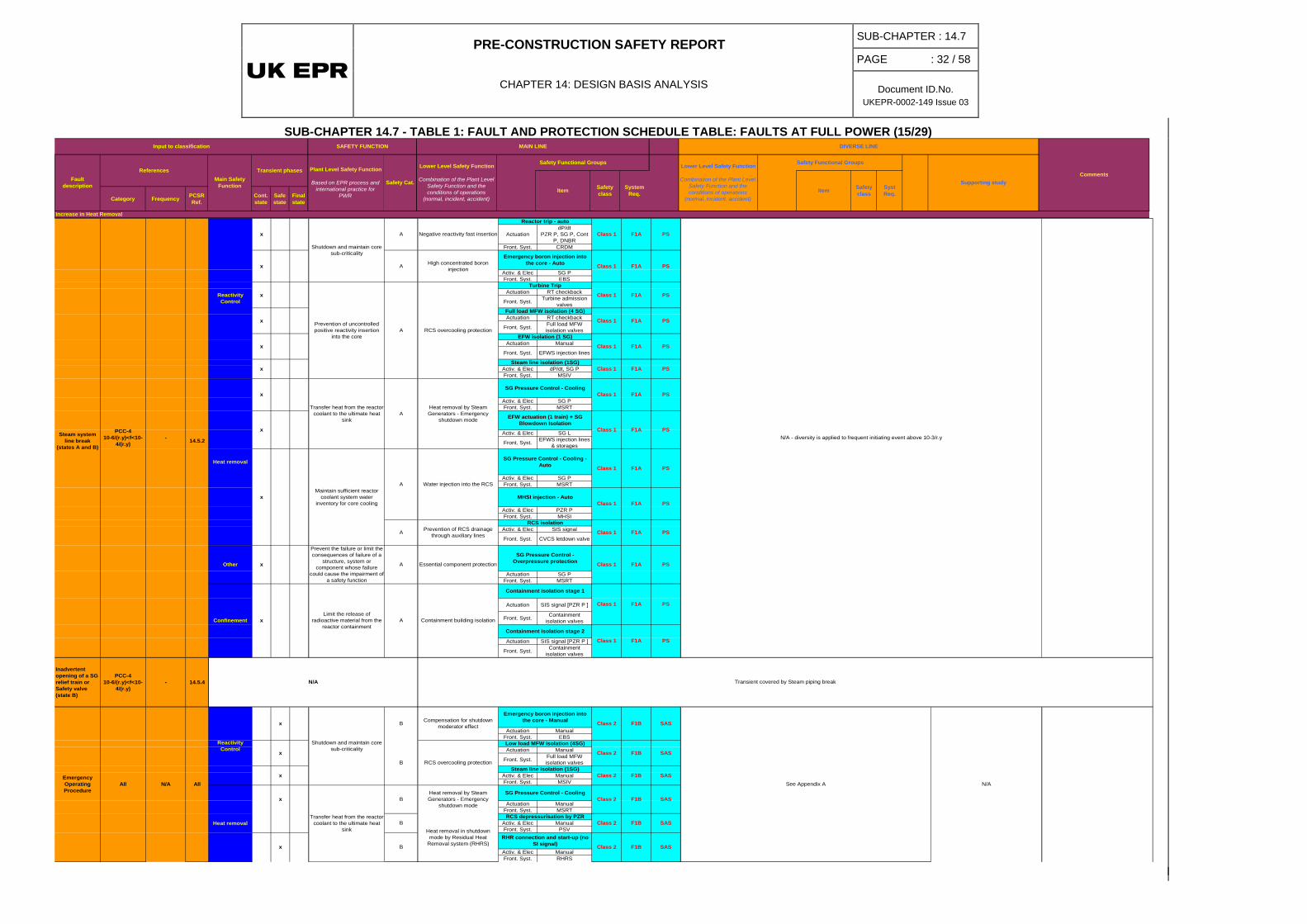
PRE-CONSTRUCTION SAFETY REPORT
CHAPTER 14: DESIGN BASIS ANALYSIS
SUB-CHAPTER : 14.7
PAGE : 32 / 58
Document ID.No. UKEPR-0002-149 Issue 03
SUB-CHAPTER 14.7 - TABLE 1: FAULT AND PROTECTION SCHEDULE TABLE: FAULTS AT FULL POWER (15/29)
Category Frequency PCSRRef.
Cont. state
Safe state
Final state
Input to classification SAFETY FUNCTION
Main Safety Function
Transient phases Plant Level Safety Function
Based on EPR process and international practice for
PWR
Safety Cat.
Lower Level Safety Function
Combination of the Plant Level Safety Function and the conditions of operations
(normal, incident, accident)
Supporting study
Safety Functional Groups
Increase in Heat Removal
CommentsLower Level Safety Function
Combination of the Plant Level Safety Function and the conditions of operations
(normal, incident, accident)
Safety class
Syst Req.
Fault description
References
DIVERSE LINE
ItemItem
MAIN LINE
Safety Functional Groups
Safety class
System Req.
ActuationdP/dt
PZR P, SG P, Cont P, DNBR
Front. Syst. CRDM
Activ. & Elec SG PFront. Syst. EBS
Actuation RT checkback
Front. Syst. Turbine admission valves
Actuation RT checkback
Front. Syst. Full load MFW isolation valves
Actuation Manual
Front. Syst. EFWS injection lines
Activ. & Elec dP/dt, SG PFront. Syst. MSIV
Activ. & Elec SG PFront. Syst. MSRT
Activ. & Elec SG L
Front. Syst. EFWS injection lines & storages
Activ. & Elec SG P Front. Syst. MSRT
Activ. & Elec PZR P Front. Syst. MHSI
Activ. & Elec SIS signal
Front. Syst. CVCS letdown valve
Actuation SG PFront. Syst. MSRT
Actuation SIS signal [PZR P ]
Front. Syst. Containment isolation valves
Actuation SIS signal [PZR P ]
Front. Syst. Containment isolation valves
Inadvertent opening of a SG relief train or Safety valve (state B)
PCC-410-6/(r.y)<f<10-
4/(r.y)- 14.5.4
Actuation ManualFront. Syst. EBS
Actuation Manual
Front. Syst. Full load MFW isolation valves
Activ. & Elec ManualFront. Syst. MSIV
Actuation ManualFront. Syst. MSRT
Activ. & Elec ManualFront. Syst. PSV
Activ. & Elec ManualFront. Syst. RHRS
F1B
F1B
F1A
F1B
F1B
F1B
F1A
F1A
F1A
Emergency Operating Procedure
Class 1
B
Heat removal
Reactivity Control
Confinement
Class 1
Class 2
-Steam system line break
(states A and B)
PCC-410-6/(r.y)<f<10-
4/(r.y)
All N/A
14.5.2
All
Heat removal
x
Other
x
x
x
Class 1
F1A
F1A
Class 1A Negative reactivity fast insertion
Emergency boron injection into the core - AutoA High concentrated boron
injection
Shutdown and maintain core sub-criticality
Reactor trip - auto
N/A - diversity is applied to frequent initiating event above 10-3/r.y
EFW isolation (1 SG)
F1A
F1A
F1A
F1A
F1A
Class 1
Class 1
Class 2
Class 1
Compensation for shutdown moderator effect
Low load MFW isolation (4SG)
Transient covered by Steam piping break
Class 1 F1A
See Appendix A
Class 2
RCS overcooling protectionSteam line isolation (1SG)
Class 2
SG Pressure Control - Cooling
Containment building isolation
SG Pressure Control - Overpressure protection
Prevention of RCS drainage through auxiliary lines
RCS isolation
SG Pressure Control - Cooling - Auto
EFW actuation (1 train) + SG Blowdown Isolation
N/A
A
Reactivity Control
x
B
Shutdown and maintain core sub-criticality
x
Limit the release of radioactive material from the
reactor containment
Transfer heat from the reactor coolant to the ultimate heat
sink
SG Pressure Control - Cooling
RHR connection and start-up (no SI signal)
Emergency boron injection into the core - Manual
Containment isolation stage 1
Class 1
Full load MFW isolation (4 SG)
Class 1
MHSI injection - AutoClass 1
Steam line isolation (1SG)
Class 1
Class 1
Class 1
Turbine Trip
N/A
Water injection into the RCS
A
Maintain sufficient reactor coolant system water
inventory for core cooling
Prevent the failure or limit the consequences of failure of a
structure, system or component whose failure
could cause the impairment of a safety function
A
A
Essential component protection
Heat removal by Steam Generators - Emergency
shutdown mode
B
x
x
B
Transfer heat from the reactor coolant to the ultimate heat
sink
B
x
x
x
x
Class 2
Containment isolation stage 2
x
AHeat removal by Steam Generators - Emergency
shutdown mode
x
x
RCS overcooling protection
x
APrevention of uncontrolled positive reactivity insertion
into the core
PS
PS
PS
PS
F1A
F1A
Heat removal in shutdown mode by Residual Heat
Removal system (RHRS)
RCS depressurisation by PZR Class 2 F1B SAS
SAS
SAS
PS
PS
PS
SAS
PS
SAS
SAS
PS
PS
PS
PS
PS
PS

PRE-CONSTRUCTION SAFETY REPORT
CHAPTER 14: DESIGN BASIS ANALYSIS
SUB-CHAPTER : 14.7
PAGE : 33 / 58
Document ID.No. UKEPR-0002-149 Issue 03
SUB-CHAPTER 14.7 - TABLE 1: FAULT AND PROTECTION SCHEDULE TABLE: FAULTS AT FULL POWER (16/29)
Category Frequency PCSRRef.
Cont. state
Safe state
Final state
Actuation PZR PSG P Actuation ATWS signal
( N-3 rod drop)
Front. Syst. CRDM Front. Syst. EBS
Actuation HL P
Front. Syst. CRDM
Actuation RT checkback Actuation SG P
Front. Syst. Turbine admission valves Front. Syst. MSIV
Actuation RT checkback Actuation RT checkbackSG L
Front. Syst. Full load MFW isolation valves Front. Syst. Full load MFW
isolation valves
Activ. & Elec SG P Activ. & Elec ManualFront. Syst. MSIV Front. Syst. MSIV
Activ. & Elec SG P Activ. & Elec ManualFront. Syst. MSRT Front. Syst. MSRT
Actuation SG P Actuation ManualFront. Syst. MSRT Front. Syst. PDS
Actuation SG L Actuation Manual
Front. Syst. EFWS injection lines & storages Front. Syst. MHSI + LHSI
Activ. & Elec ManualFront. Syst. RCP
Actuation SG P Actuation Passive
Front. Syst. MSRT Front. Syst. MSSV
Actuation Passive Activ. & Elec PassiveFront. Syst. PSV Front. Syst. PSV
Actuation SG LPZR P Actuation ATWS signal
( N-3 rod drop)
Front. Syst. CRDM Front. Syst. EBS
Actuation RT checkback Actuation SG P
Front. Syst. Turbine admission valves Front. Syst. MSIV
Actuation SG P Actuation ManualFront. Syst. MSRT Front. Syst. PDS
Actuation SG L Actuation Manual
Front. Syst. EFWS injection lines & storages Front. Syst. MHSI + LHSI
Activ. & Elec ManualFront. Syst. RCP
Actuation SG P Actuation PassiveFront. Syst. MSRT Front. Syst. MSSV
Actuation Passive Activ. & Elec PassiveFront. Syst. PSV Front. Syst. PSV
x Shutdown and maintain core sub-criticality A Negative reactivity fast
insertion
-
SAS
SAS
-
PS
PS
SAS
SAS
SAS
-
-
PSF2
F1A
F1B
F1B
F1A
SAS
SAS
SAS
SAS
F1B
F2
F2
F1B
Emergency boron injection into the core - diversified
F2
Class 2
PS
PS
PS
PS
Full load MFW isolation (4SG)
Class 2
RCS overcooling protection
MSIV closure
Syst Req.Item
Emergency boron injection into the core - diversified
Safety Functional Groups
Safety class
Class 1
F2
F1A
Class 2
Class 1
F1A
F2
Reactor trip - auto
Class 2
MAIN LINE
Safety Functional Groups
High concentrated and high pressure boron injection
Reactor trip - auto
Lower Level Safety Function
Combination of the Plant Level Safety Function and the conditions of operations
(normal, incident, accident)
PS
DIVERSE LINE
Supporting study
F1A
F1A
Safety class
System Req.
Class 1
F1A
F1A
RCS overcooling protection
Full load MFW isolation (4SG)
Turbine Trip
Class 1
Steam line isolation (1SG)
MSRT isolation (1 SG isolation valve closure)
Class 1
Class 1
Sequences of primary bleed and feed detailed in case of Total Loss Of FeedWater
RRC-A
Secondary overpressure studies of Sub-chapter 3.4.1.5 illustrate
Primary overpressure studies of Sub-chapter 3.4.1.5 illustrateF1A
F1B
MSIV closure
Class 2
SASF1B
PS
2.5.10-1
1.5.10-1
6.25.10-3
Reactivity Control
Reactor trip - auto
EFW actuation (1 train) + SG
Maintain integrity of the Reactor Coolant Pressure
BoundaryA RCS overpressure protectionConfinement x
Prevent the failure or limit the consequences of failure of a
structure, system or component whose failure
could cause the impairment of a safety function
Essential component protectionA Essential component protection
SG Pressure Control - Overpressure protection
Class 1 F1A
SG safety valves opening
Hot overpressure protectionRCS overpressure protection
PS Class 1
Class 1
Class 1
RCP stop - ManuClass 2
EFW actuation (1 train) + SG Heat removal by Low Head Emergency Core Cooling
System (ECCS)
Opening of severe accident discharge line Class 2
SIS [RIS] in cold leg
Class 2
Class 2
MSRT isolation (1 SG isolation valve closure)
Steam line isolation (1SG)
Class 2
Maintain integrity of the Reactor Coolant Pressure
Boundary
Ax
Prevent the failure or limit the consequences of failure of a
structure, system or component whose failure
could cause the impairment of a safety function
x
Class 2x
Heat removal by Low Head Emergency Core Cooling
System (ECCS)PS
F1A
Transfer heat from the reactor coolant to the ultimate heat
sink
x
Class 1F1A F1A
RCP stop - ManuClass 2
AHeat removal by Steam Generators - Emergency
shutdown mode
SG Pressure Control - Cooling
Class 1
SG safety valves opening
SIS [RIS] in cold leg
Opening of severe accident discharge line
F1A
Essential component protection Essential component protection
SG Pressure Control - Overpressure protection Class 1 PS
x
x
x
SG Pressure Control - Cooling
Transfer heat from the reactor coolant to the ultimate heat
sinkA
Heat removal by Steam Generators - Emergency
shutdown mode
A
Plant Level Safety Function
Based on EPR process and international practice for
PWR
Safety Cat.
Lower Level Safety Function
Combination of the Plant Level Safety Function and the conditions of operations
(normal, incident, accident)
Negative reactivity fast insertionShutdown and maintain core sub-criticality
Loss of normal feedwater flow
PCC-2f>10-2/(r.y) 14.3.7
Heat removal
Confinement
Other
A RCS overpressure protection RCS overpressure protectionHot overpressure protection
Class 1 F1A -
PS
RCS overcooling protection
PS
PS
High concentrated and high pressure boron injection
F1A
F1A PS
F1A
F1A
-
Class 1
F1A PS
Turbine Trip
Shutdown and maintain core sub-criticality
Prevention of uncontrolled positive reactivity insertion
into the coreClass 1
Hot overpressure protection
A Negative reactivity fast insertion
Class 1
Class 1
A RCS overcooling protection
A
x
Class 1
TT initiating event
-
Excessive increase in steam flow study
SAS order in case of ATWS following PS failure
-
Only in case of loss of condenser (1) due to the single failure on MSRIV and small feedwater system piping (3) due to the
break.
Class 1
Prevention of uncontrolled positive reactivity insertion
into the core
Heat removal
x
x
x
x
Fault description
Input to classification
References Transient phasesMain Safety
Function
SAFETY FUNCTION
Turbine Trip
Loss of condenser
vacuum
PCC-2f>10-2/(r.y)
14.3.4
14.3.5
x
x
Other x
x
Reactivity Control
Hot overpressure protectionClass 1
Comments
ATWS are not postulated for PCC-3 and PCC-4 events
PCSR Sub-chapter 16.1.3.3.1 - ATWS LOFW by rod drop failure covers the ATWS
LOCV
Decrease in Heat Removal
Item
F1A
Primary overpressure studies of Sub-chapter 3.4.1.5 illustrate
Only in case of loss of condenser (1), due to the single failure on MSRIV
Sequences of primary bleed and feed detailed in case of Total Loss Of FeedWater
RRC-A
PCSR Sub-chapter 16.1.3.3.1 - ATWS LOMFW
A partial trip may occur before actuation of the RT on loss of normal feedwater. See
Total Loss of FeedWater sequence below
Excessive increase in steam flow study
Secondary overpressure studies of Sub-chapter 3.4.1.5 illustrate

PRE-CONSTRUCTION SAFETY REPORT
CHAPTER 14: DESIGN BASIS ANALYSIS
SUB-CHAPTER : 14.7
PAGE : 34 / 58
Document ID.No. UKEPR-0002-149 Issue 03
SUB-CHAPTER 14.7 - TABLE 1: FAULT AND PROTECTION SCHEDULE TABLE: FAULTS AT FULL POWER (17/29)
Category Frequency PCSRRef.
Cont. state
Safe state
Final state
Input to classification SAFETY FUNCTION
Main Safety Function
Transient phases Plant Level Safety Function
Based on EPR process and international practice for
PWR
Safety Cat.
Lower Level Safety Function
Combination of the Plant Level Safety Function and the conditions of operations
(normal, incident, accident)
Supporting study
Safety Functional Groups
Increase in Heat Removal
CommentsLower Level Safety Function
Combination of the Plant Level Safety Function and the conditions of operations
(normal, incident, accident)
Safety class
Syst Req.
Fault description
References
DIVERSE LINE
ItemItem
MAIN LINE
Safety Functional Groups
Safety class
System Req.
Actuation HCPL / DNBRSG P Actuation ATWS signal
( N-3 rod drop)Front. Syst. CRDM Front. Syst. EBS
Actuation high neutron fluxHL P
Front. Syst. CRDM
Actuation RT checkback Actuation SG P
Front. Syst. Turbine admission valves Front. Syst. MSIV
Actuation RT checkback Actuation RT checkback
Front. Syst. Full load MFW isolation valves Front. Syst. Full load MFW
isolation valves
Activ. & Elec SG P Activ. & Elec ManualFront. Syst. MSIV Front. Syst. MSIV
Actuation SG P Actuation ManualFront. Syst. MSRT Front. Syst. PDS
Actuation SG L Actuation Manual
Front. Syst. EFWS injection lines & storages Front. Syst. MHSI + LHSI
Activ. & Elec ManualFront. Syst. RCP
Actuation SG P Actuation PassiveFront. Syst. MSRT Front. Syst. MSSV
Actuation Passive Activ. & Elec PassiveFront. Syst. PSV Front. Syst. PSV
Actuation PZR PSG P Actuation ATWS signal
( N-3 rod drop)Front. Syst. CRDM Front. Syst. EBS
Actuation RT checkback Actuation SG P
Front. Syst. Turbine admission valves Front. Syst. MSIV
Actuation RT checkback Actuation RT checkback
Front. Syst. Full load MFW isolation valves Front. Syst. Full load MFW
isolation valves
Actuation SG P Actuation ManualFront. Syst. MSRT Front. Syst. PDS
Actuation SG L Actuation Manual
Front. Syst. EFWS injection lines & storages Front. Syst. MHSI + LHSI
Activ. & Elec ManualFront. Syst. RCP
Actuation SG P Actuation PassiveFront. Syst. MSRT Front. Syst. MSSV
Actuation Passive Activ. & Elec PassiveFront. Syst. PSV Front. Syst. PSV
x Class 2 F2 SAS
F2
F1B
Reactor trip - auto
F1B
F1A
F1B
F1A
Transfer heat from the reactor coolant to the ultimate heat
sink
F2
F1B
Shutdown and maintain core sub-criticality A Negative reactivity fast
insertion
Opening of severe accident discharge lineF1A
Opening of severe accident discharge line
-
SAS
SAS
SAS
-
PS
-
PS
PS
SAS
SAS
SAS
SAS
F2
SG safety valves openingClass 1
Class 2
SIS [RIS] in cold leg
Class 2
Class 1
F1A
F1A
F1A
Class 1 F1A
Class 1
F2
Turbine Trip
Class 2SG Pressure Control - Cooling
Class 1
MSIV closure
F1A
F1A
F1A
x
x
x
Class 2
xMaintain integrity of the
Reactor Coolant Pressure Boundary
x
Prevent the failure or limit the consequences of failure of a
structure, system or component whose failure
could cause the impairment of a safety function
A Essential component protection Essential component protection
SG Pressure Control - Overpressure protection Class 1 F1A PS
x
x
xA
Heat removal by Steam Generators - Emergency
shutdown mode
Heat removal by Low Head Emergency Core Cooling
System (ECCS)
EFW actuation (1 train) + SG
Class 1 F1A
PS
PS
Class 1
Sequences of primary bleed and feed detailed in case of Total Loss Of FeedWater
RRC-A
Hot overpressure protectionClass 1
Hot overpressure protection
Class 2
Secondary overpressure studies of Sub-chapter 3.4.1.5 illustrate
SG safety valves opening
RCP stop - Manu
Class 1
SIS [RIS] in cold leg
-
A RCS overcooling protection RCS overcooling protection
Excessive increase in steam flow study
Full load MFW isolation (4SG)
Class 1
Full load MFW isolation (4SG)
Class 1
Class 2
xPrevention of uncontrolled positive reactivity insertion
into the core
x
A Negative reactivity fast insertion High concentrated and high pressure boron injection
PCSR Sub-chapter 16.1.3.3.1 - ATWS LOFW
Reactor trip - auto
Class 1
Emergency boron injection into the core - diversified
Class 2F1A F2x Shutdown and maintain core sub-criticality
Inadvertent closure of one / all main steam isolation valves
PCC-310-4/(r.y)<f<10-
2/(r.y) 14.4.7
Reactivity Control
Confinement
Other
Heat removal
1 MSIV:1.8.10-2
All MSIV:2.10-3
Primary overpressure studies of Sub-chapter 3.4.1.5 illustrate
Hot overpressure protectionClass 1
Hot overpressure protectionClass 1F1A F1A --A RCS overpressure protection RCS overpressure protection
Essential component protection
SG Pressure Control - Overpressure protectionA
xMaintain integrity of the
Reactor Coolant Pressure Boundary
Secondary overpressure studies of Sub-chapter 3.4.1.5 illustrate
RCP stop - Manu
x
Prevent the failure or limit the consequences of failure of a
structure, system or component whose failure
could cause the impairment of a safety function
Essential component protectionF1A
Sequences of primary bleed and feed detailed in case of Total Loss Of FeedWater
RRC-A
F1A
EFW actuation (1 train) + SG Heat removal by Low Head Emergency Core Cooling
System (ECCS)
Class 1SG Pressure Control - Cooling
Transfer heat from the reactor coolant to the ultimate heat
sinkA
Heat removal by Steam Generators - Emergency
shutdown mode
A RCS overcooling protection
Negative reactivity fast insertion
SAS
Class 1
F1B
High concentrated and high pressure boron injection
Reactor trip - auto
PS
PS SAS order in case of ATWS following PS failure
MSIV closure
PS
SASF2Class 2
x
Prevention of uncontrolled positive reactivity insertion
into the corex
x
Full load MFW isolation (4SG)
Steam line isolation (1SG)
F1A
Steam line isolation (1SG)
Emergency boron injection into the core - diversified
F1A PS
RCS overcooling protection
Shutdown and maintain core sub-criticality
Small feedwater system piping
failure
PCC-310-4/(r.y)<f<10-
2/(r.y) 14.4.1
Reactivity Control
Confinement
2.10-3
Other
Heat removal
x A
-
ATWS are not postulated for PCC-3 and PCC-4 events
Class 2
Class 2
PCSR Sub-chapter 16.1.3.3.1 - ATWS LOFW
Excessive increase in steam flow study
Class 2
The overpressure protection is ensured thnaks to the 3 PSVs. It can be
demonstrated that no CCF will impair the
A RCS overpressure protection RCS overpressure protection Primary overpressure studies of Sub-chapter 3.4.1.5 illustrateClass 1F1A - F1A
Class 1
Full load MFW isolation (4SG)
Turbine Trip
Class 1
Class 1
PS
PS
PS
PS
PS
PS
PS

PRE-CONSTRUCTION SAFETY REPORT
CHAPTER 14: DESIGN BASIS ANALYSIS
SUB-CHAPTER : 14.7
PAGE : 35 / 58
Document ID.No. UKEPR-0002-149 Issue 03
SUB-CHAPTER 14.7 - TABLE 1: FAULT AND PROTECTION SCHEDULE TABLE: FAULTS AT FULL POWER (18/29)
Category Frequency PCSRRef.
Cont. state
Safe state
Final state
Input to classification SAFETY FUNCTION
Main Safety Function
Transient phases Plant Level Safety Function
Based on EPR process and international practice for
PWR
Safety Cat.
Lower Level Safety Function
Combination of the Plant Level Safety Function and the conditions of operations
(normal, incident, accident)
Supporting study
Safety Functional Groups
Increase in Heat Removal
CommentsLower Level Safety Function
Combination of the Plant Level Safety Function and the conditions of operations
(normal, incident, accident)
Safety class
Syst Req.
Fault description
References
DIVERSE LINE
ItemItem
MAIN LINE
Safety Functional Groups
Safety class
System Req.
Actuation dP/dtSG L
Front. Syst. CRDM
Actuation RT checkback
Front. Syst. Turbine admission valves
Activ. & Elec dP/dtFront. Syst. MSIV
Actuation SG PFront. Syst. MSRT
Actuation SG L
Front. Syst. EFWS injection lines & storages
Actuation Manual
Front. Syst. EFWS injection lines & storages
Actuation SG PFront. Syst. MSRT
Actuation PassiveFront. Syst. PSV
Actuation ManualFront. Syst. EBS
Actuation ManualFront. Syst. MSRT
Actuation Manual
Front. Syst. EFWS injection lines
Actuation ManualFront. Syst. PSV
Activ. & Elec ManualFront. Syst. RHRS
Confinement x N/A
x Class 2 F1B SAS
F1A
F1A
F1A
F1A
F1A
F1A
N/A - diversity is applied to frequent initiating event above 10-3/r.y
F1A
F1A
Class 1
Class 1
* Only the EFWS of the SG affected by the FeedWater Line Break is isolated - whatever
the size of the break.F1A See Appendix A
F1B
RCS depressurisation by PZR safety valves
PS
SAS
F1B
F1B
Emergency Operating Procedure B
B
BHeat removal in shutdown
mode by Residual Heat Removal system (RHRS)
B
Transfer heat from the reactor coolant to the ultimate heat
sink
x
x
Compensation for shutdown moderator effect
Emergency boron injection into the core - Manual Class 2
RHR connection and start-up (no SI signal)
Class 2SG Pressure Control - Cooling
Class 1
Class 2
EFW isolation*
Heat removal by Steam Generators - Emergency
shutdown mode
x
x
x
Heat removal
All N/A All
Reactivity Control
Heat removal
Turbine Trip
x Shutdown and maintain core sub-criticality B
x
Class 1
Class 1
Class 1
Essential component protection
SG Pressure Control - Overpressure protection Class 1
Hot overpressure protectionClass 1RCS overpressure protection
Prevent the failure or limit the consequences of failure of a
structure, system or component whose failure
could cause the impairment of
AMaintain integrity of the
Reactor Coolant Pressure Boundary
A
AHeat removal by Steam Generators - Emergency
shutdown mode
SG Pressure Control - Cooling
EFW actuation (1 train) + SG
Re-alignment of EFWS pump discharge & suction
Steam line isolation (1SG)
x Transfer heat from the reactor coolant to the ultimate heat
sink
x
A RCS overcooling protection
A Negative reactivity fast insertion
x Prevention of uncontrolled positive reactivity insertion
into the core
x
Reactor trip - auto
Class 1x Shutdown and maintain core sub-criticality
Feedwater line break
PCC-410-6/(r.y)<f<10-
4/(r.y)14.5.3
Reactivity Control
Other
Confinement
-
PS
PS
PS
PS
PS
-
PS
-
SAS
SAS

PRE-CONSTRUCTION SAFETY REPORT
CHAPTER 14: DESIGN BASIS ANALYSIS
SUB-CHAPTER : 14.7
PAGE : 36 / 58
Document ID.No. UKEPR-0002-149 Issue 03
SUB-CHAPTER 14.7 - TABLE 1: FAULT AND PROTECTION SCHEDULE TABLE: FAULTS AT FULL POWER (19/29)
Category Frequency PCSRRef.
Cont. state
Safe state
Final state
Input to classification SAFETY FUNCTION
Main Safety Function
Transient phases Plant Level Safety Function
Based on EPR process and international practice for
PWR
Safety Cat.
Lower Level Safety Function
Combination of the Plant Level Safety Function and the conditions of operations
(normal, incident, accident)
Supporting study
Safety Functional Groups
Increase in Heat Removal
CommentsLower Level Safety Function
Combination of the Plant Level Safety Function and the conditions of operations
(normal, incident, accident)
Safety class
Syst Req.
Fault description
References
DIVERSE LINE
ItemItem
MAIN LINE
Safety Functional Groups
Safety class
System Req.
ActuationLow RCP speedLow RCS loop
flowrateFront. Syst. CRDM
Actuation RT checkback
Front. Syst. Turbine admission valves
Actuation RT checkback
Front. Syst. Full load MFW isolation valves
Actuation ManualFront. Syst. MSRT
Actuation SIS signal [PZR P ]Front. Syst. MHSI
Actuation SIS signal [PZR P ]Front. Syst. MSRT
Actuation ManualFront. Syst. LHSI
Actuation SIS signal [PZR P ]
Front. Syst. CVCS letdown valve
Actuation SG PFront. Syst. MSRT
Actuation SG L
Front. Syst. EFWS injection lines & storages
Actuation Manual
Front. Syst. CHRS
Actuation Manual
Front. Syst. Containment isolation valves
Loss of one cooling train of the SIS / RHRS in RHR mode (states C & D)
PCC-2f>10-2/(r.y) > 1.10-2 14.3.17 Heat removal x
Transfer heat from the reactor coolant to the ultimate heat
sinkA
Heat removal in shutdown mode by Residual Heat
Removal System (RHRS)
B F1BContainment building isolation
Containment isolation
xLimit the release of
radioactive material from the reactor containment
SG Pressure Control - Cooling
Turbine Trip
SAS
PS
Reactor trip - auto
PS
MHSI injection - Auto
LHSI injection diversified
Transient without any consequences as 2 LHSI / RHRS in operation are sufficient to guarantee heat removal - the operator can actuate another
RHR train - Class 2
F1B
F1A
F1A
F2
PS
PS
Class 1 F1A
x
EFW actuation (1 train) + SG Transfer heat from the reactor
coolant to the ultimate heat sink
SG Pressure Control - Cooling
B
x
Heat removal from containment by Containment Heat Removal
system (CHRS)
Total Loss Of the Cooling
Chain leading to a leakage on RCP [RCS]
pumps seals (state A)
TLOCC in state D
RRC-A -16.3.5
16.3.11
Reactivity Control
Confinement
x
The diversity can be illustrated by the Total Loss of Cooling Chain sequences
SG Pressure Control - Cooling
PS
PS
B
Water injection into the RCSB
B Negative reactivity fast insertionShutdown and maintain core sub-criticality
See Appendix A
F1AClass 1
F1A
Class 1
PS
Class 2
F1A
F1A
SAS
This part of transient is valid as long as the cooling of MHSI pumps is efficient (~5
minutes). Later the MHSI are lost and the end of the transient is similar to the RRC-A
sequences SB LOCA with loss of MHSI. However, in case of TLOCC, there is a need
to consider a diverse cooling chaing constituted by the 2 LHSI trains connected to the diverse cooling chain with EVU/SRU.
TLOCC in state D relies on the CHRS [EVU] capacities to remove heat with the same features as the one of TLOCC in state A.
Class 1
Class 1
Class 1
Class 2
Class 1
Class 2
PS
SAS
Heat removal
x
Heat removal by Steam Generators - Emergency
shutdown mode
Maintain sufficient Reactor Coolant System water
inventory for core cooling
x
x
Start-up of IRWST pool cooling by CHRS
Class 2 F2
x
SAS
Full load MFW isolation (4SG)RCS overcooling protection
Prevention of RCS drainage through auxiliary lines
Isolation of CVCS letdown line
F1A
B
Class 1
Prevention of uncontrolled positive reactivity insertion
into the core
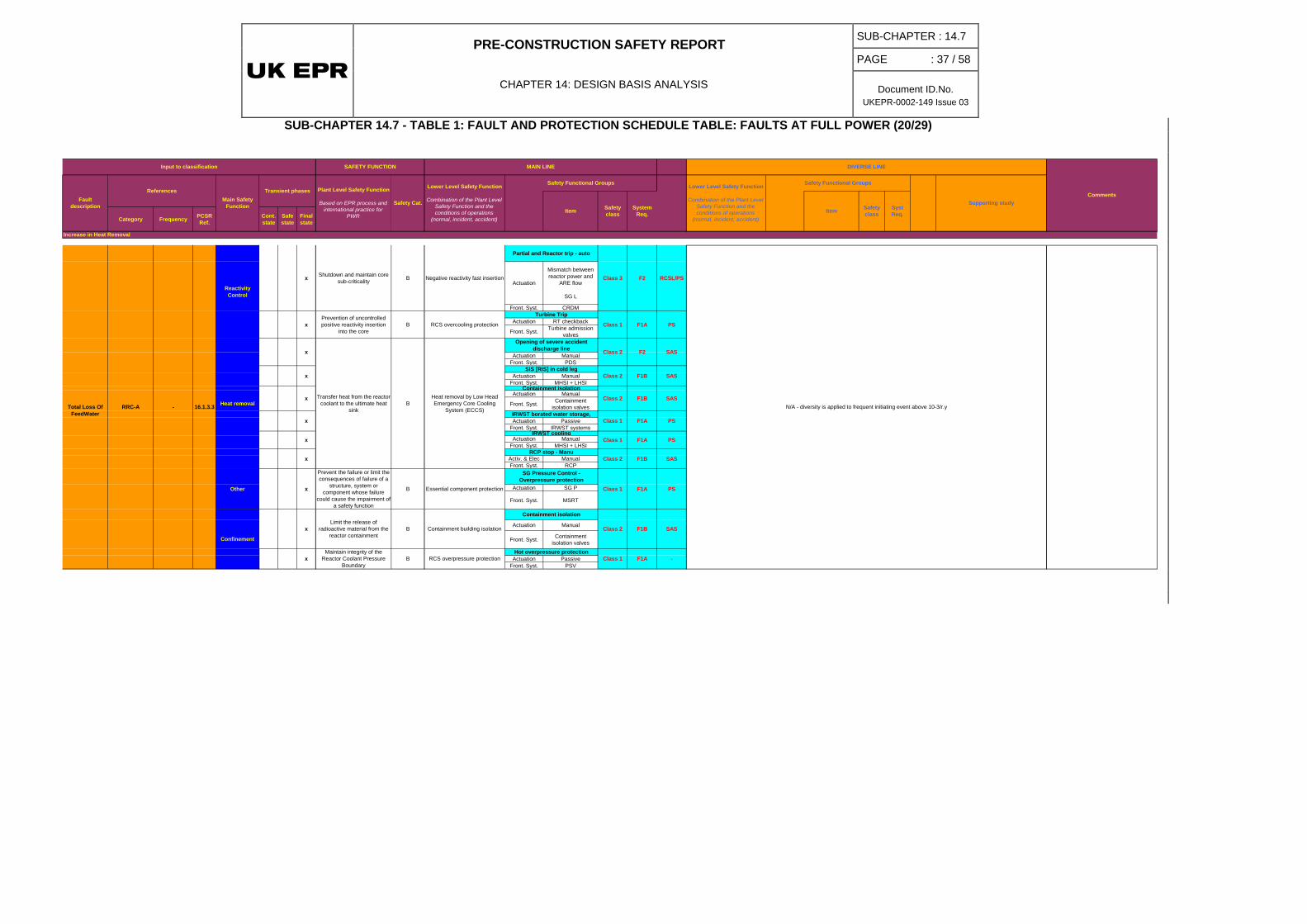
PRE-CONSTRUCTION SAFETY REPORT
CHAPTER 14: DESIGN BASIS ANALYSIS
SUB-CHAPTER : 14.7
PAGE : 37 / 58
Document ID.No. UKEPR-0002-149 Issue 03
SUB-CHAPTER 14.7 - TABLE 1: FAULT AND PROTECTION SCHEDULE TABLE: FAULTS AT FULL POWER (20/29)
Category Frequency PCSRRef.
Cont. state
Safe state
Final state
Input to classification SAFETY FUNCTION
Main Safety Function
Transient phases Plant Level Safety Function
Based on EPR process and international practice for
PWR
Safety Cat.
Lower Level Safety Function
Combination of the Plant Level Safety Function and the conditions of operations
(normal, incident, accident)
Supporting study
Safety Functional Groups
Increase in Heat Removal
CommentsLower Level Safety Function
Combination of the Plant Level Safety Function and the conditions of operations
(normal, incident, accident)
Safety class
Syst Req.
Fault description
References
DIVERSE LINE
ItemItem
MAIN LINE
Safety Functional Groups
Safety class
System Req.
Actuation
Mismatch between reactor power and
ARE flow
SG L
Front. Syst. CRDM
Actuation RT checkback
Front. Syst. Turbine admission valves
Actuation ManualFront. Syst. PDS
Actuation ManualFront. Syst. MHSI + LHSI
Actuation Manual
Front. Syst. Containment isolation valves
Actuation PassiveFront. Syst. IRWST systems
Actuation ManualFront. Syst. MHSI + LHSI
Activ. & Elec ManualFront. Syst. RCP
Actuation SG P
Front. Syst. MSRT
Actuation Manual
Front. Syst. Containment isolation valves
Actuation PassiveFront. Syst. PSV
Class 1
Confinement
F1A
Class 2
B
F1B
Maintain integrity of the Reactor Coolant Pressure
Boundary
x Containment building isolation
Class 1
BLimit the release of
radioactive material from the reactor containment
Class 2
Essential component protection
SG Pressure Control - Overpressure protection
Class 1
x Class 2 F1B SAS
F2
F1A
F2Class 2
F1A PS
PS
N/A - diversity is applied to frequent initiating event above 10-3/r.y
Class 2
Class 1
Class 3
Transfer heat from the reactor coolant to the ultimate heat
sinkB
RCSL/PS
SAS
Heat removal by Low Head Emergency Core Cooling
System (ECCS)
Class 1
RCS overcooling protection
Partial and Reactor trip - auto
SIS [RIS] in cold leg
F1A
F1A
F1B SAS
SAS
PS
-
F1B SAS
RCS overpressure protection
RCP stop - Manu
Hot overpressure protection
Containment isolation
IRWST cooling
Containment isolation
Turbine Trip
Opening of severe accident discharge line
IRWST borated water storage,
x
x
x
Shutdown and maintain core sub-criticality B Negative reactivity fast insertion
Reactivity Control
x
Total Loss Of FeedWater
RRC-A - 16.1.3.3
x
B
x
x
Prevention of uncontrolled positive reactivity insertion
into the core
x
Other
Heat removal
x
Prevent the failure or limit the consequences of failure of a
structure, system or component whose failure
could cause the impairment of a safety function
B
PS

PRE-CONSTRUCTION SAFETY REPORT
CHAPTER 14: DESIGN BASIS ANALYSIS
SUB-CHAPTER : 14.7
PAGE : 38 / 58
Document ID.No. UKEPR-0002-149 Issue 03
SUB-CHAPTER 14.7 - TABLE 1: FAULT AND PROTECTION SCHEDULE TABLE: FAULTS AT FULL POWER (21/29)
Category Frequency PCSRRef.
Cont. state
Safe state
Final state
Input to classification SAFETY FUNCTION
Main Safety Function
Transient phases Plant Level Safety Function
Based on EPR process and international practice for
PWR
Safety Cat.
Lower Level Safety Function
Combination of the Plant Level Safety Function and the conditions of operations
(normal, incident, accident)
Supporting study
Safety Functional Groups
Increase in Heat Removal
CommentsLower Level Safety Function
Combination of the Plant Level Safety Function and the conditions of operations
(normal, incident, accident)
Safety class
Syst Req.
Fault description
References
DIVERSE LINE
ItemItem
MAIN LINE
Safety Functional Groups
Safety class
System Req.
ActuationLow RCP speedLow RCS loop
flowrateFront. Syst. CRDM
Actuation RT checkback
Front. Syst. Turbine admission valves
Actuation RT checkback
Front. Syst. Full load MFW isolation valves
Actuation ManualFront. Syst. MSRT
Actuation SIS signal [PZR P ]Front. Syst. MHSI
Actuation SIS signal [PZR P ]Front. Syst. MSRT
Actuation ManualFront. Syst. LHSI
Actuation SIS signal [PZR P ]
Front. Syst. CVCS letdown valve
Actuation SG PFront. Syst. MSRT
Actuation SG L
Front. Syst. EFWS injection lines & storages
Actuation Manual
Front. Syst. CHRS
Actuation Manual
Front. Syst. Containment isolation valves
Loss of one cooling train of the SIS / RHRS in RHR mode (states C & D)
PCC-2f>10-2/(r.y) > 1.10-2 14.3.17 Heat removal x
Transfer heat from the reactor coolant to the ultimate heat
sinkA
Heat removal in shutdown mode by Residual Heat
Removal System (RHRS)
B F1BContainment building isolation
Containment isolation
xLimit the release of
radioactive material from the reactor containment
SG Pressure Control - Cooling
Turbine Trip
SAS
PS
Reactor trip - auto
PS
MHSI injection - Auto
LHSI injection diversified
Transient without any consequences as 2 LHSI / RHRS in operation are sufficient to guarantee heat removal - the operator can actuate another
RHR train - Class 2
F1B
F1A
F1A
F2
PS
PS
Class 1 F1A
x
EFW actuation (1 train) + SG Transfer heat from the reactor
coolant to the ultimate heat sink
SG Pressure Control - Cooling
B
x
Heat removal from containment by Containment Heat Removal
system (CHRS)
Total Loss Of the Cooling
Chain leading to a leakage on RCP [RCS]
pumps seals (state A)
TLOCC in state D
RRC-A -16.3.5
16.3.11
Reactivity Control
Confinement
x
The diversity can be illustrated by the Total Loss of Cooling Chain sequences
SG Pressure Control - Cooling
PS
PS
B
Water injection into the RCSB
B Negative reactivity fast insertionShutdown and maintain core sub-criticality
See Appendix A
F1AClass 1
F1A
Class 1
PS
Class 2
F1A
F1A
SAS
This part of transient is valid as long as the cooling of MHSI pumps is efficient (~5
minutes). Later the MHSI are lost and the end of the transient is similar to the RRC-A
sequences SB LOCA with loss of MHSI. However, in case of TLOCC, there is a need
to consider a diverse cooling chaing constituted by the 2 LHSI trains connected to the diverse cooling chain with EVU/SRU.
TLOCC in state D relies on the CHRS [EVU] capacities to remove heat with the same features as the one of TLOCC in state A.
Class 1
Class 1
Class 1
Class 2
Class 1
Class 2
PS
SAS
Heat removal
x
Heat removal by Steam Generators - Emergency
shutdown mode
Maintain sufficient Reactor Coolant System water
inventory for core cooling
x
x
Start-up of IRWST pool cooling by CHRS
Class 2 F2
x
SAS
Full load MFW isolation (4SG)RCS overcooling protection
Prevention of RCS drainage through auxiliary lines
Isolation of CVCS letdown line
F1A
B
Class 1
Prevention of uncontrolled positive reactivity insertion
into the core

PRE-CONSTRUCTION SAFETY REPORT
CHAPTER 14: DESIGN BASIS ANALYSIS
SUB-CHAPTER : 14.7
PAGE : 39 / 58
Document ID.No. UKEPR-0002-149 Issue 03
SUB-CHAPTER 14.7 - TABLE 1: FAULT AND PROTECTION SCHEDULE TABLE: FAULTS AT FULL POWER (22/29)
Category Frequency PCSRRef.
Cont. state
Safe state
Final state
ActuationLow RCP speedLow RCS loop
flowrateActuation ATWS signal
( N-3 rod drop)
Front. Syst. CRDM Front. Syst. EBS
Actuation Low RCP speed
Front. Syst. CRDM
Actuation RT checkback Actuation SG P
Front. Syst. Turbine admission valves Front. Syst. MSIV
Actuation SG P Actuation ManualFront. Syst. MSRT Front. Syst. PDS
Actuation SG L Actuation Manual
Front. Syst. EFWS injection lines & storages Front. Syst. MHSI + LHSI
Activ. & Elec ManualFront. Syst. RCP
Actuation LOOP Actuation ManualFront. Syst. UDG-DG Front. Syst. UDG-DG
Actuation SG P Actuation PassiveFront. Syst. MSRT Front. Syst. MSSV
Actuation Passive Activ. & Elec PassiveFront. Syst. PSV Front. Syst. PSV
Actuation ManualFront. Syst. EBS
Actuation ManualFront. Syst. MSRT
Actuation ManualFront. Syst. PSV
Activ. & Elec ManualFront. Syst. RHRS
ActuationLow RCP speedLow RCS loop
flowrateFront. Syst. CRDM
Actuation RT checkback
Front. Syst. Turbine admission valves
Actuation ManualFront. Syst. MSRT
Actuation Manual
Front. Syst. EFWS injection lines & storages
Actuation Manual
Front. Syst. EFWS injection lines & storages
Actuation ManualFront. Syst. UDG diesels
Actuation RCP TFront. Syst. SSSS
Actuation SG PFront. Syst. MSRT
Actuation PassiveFront. Syst. PSV
SHU
TDO
WN
MO
DE
Long-term LOOP in state C
(>2 hours)
PCC-410-6/(r.y)<f<10-
4/(r.y)- 14.5.1 Heat removal x
Transfer heat from the reactor coolant to the ultimate heat
sinkA
Heat removal in shutdown mode by Residual Heat
Removal System (RHRS)
The automatic start-up of the EDGs ensure the heat removal with the LHSI/RHRS trains
This heat removal is ensured once the EDGs have been automatically started - this automatic start is Class 1
Heat removal
Class 1EDG start-up
Transfer heat from the reactor coolant to the ultimate heat
sink
x
PS
-
PCSR Sub-chapter 16.1.3.3.4 or 16.1.3.3.3 for electrical supply diversity (see below
RRC-A Station Black-out)
The electrical supply of the systems is made by the 2h batteries and the 4 EDGs. In case of failureof the 4 EDGs there are 2 Station
Black-out diesels starting the EFWS pumps of trains 1 and 4.
Heat removal by Low Head Emergency Core Cooling
System (ECCS)
Heat removal by Steam Generators - Emergency
shutdown mode
F1A PSUDG-DG start-up
Class 2 F2 -
Negative reactivity fast insertion
Shutdown and maintain core sub-criticality A
PSClass 1
Reactor trip - auto
Class 2 F2 SAS
PS
PS
SAS
SAS
SAS
-
-
-
F1B
F1A
F1AHot overpressure protection
Reactor trip - auto
SAS
PAS
SAS
PS
PS
SAS
F1B
-
SAS
SAS
SAS
SAS
F1A
F1B
F1B
F1A
F1B
F1B
F1B
F1B
F2
F1A
F2
F1B
Turbine Trip
F2
F1A
F1A
SG Pressure Control - Overpressure protection Class 1
Hot overpressure protection
SG Pressure Control - Overpressure protection
F1A
Class 1
MAIN LINE
Safety Functional Groups Safety Functional Groups
Safety class
System Req.
Safety class
Syst Req.
MSIV closure
Class 1
Hot overpressure protectionClass 1
PS
PS
PS
F1A
F1A
F1A
All
Reactivity Control
x
xHeat removal
B
xMaintain integrity of the
Reactor Coolant Pressure Boundary
A
x
POW
ER O
PER
ATI
ON
S
Emergency Operating Procedure All N/A
Short-term LOOP (<2
hours)
Long-term LOOP (>2
hours)
PCC-2f>10-2/(r.y)
PCC-310-4/(r.y)<f<10-
2/(r.y)
Station Black-out in state A RRC-A -
6.10-2
1.10-3
16.1.3.3
Reactivity Control
Confinement
Other
F1A
RCS overpressure protection
A Essential component protection
Prevent the failure or limit the consequences of failure of a
structure, system or component whose failure
could cause the impairment of a safety function
Shutdown and maintain core sub-criticality
Primary overpressure studies of Sub-chapter 3.4.1.5 illustrateClass 1
The overpressure protection is ensured thanks to the 3 PSVs. It can be
demonstrated that no CCF will impair the operation of the 3 PSVs at the same time.
RCS overpressure protection
Whatever the length of the LOOP, the safety systems actuated are supported by batteries
and EDGs allowing
RHR connection and start-up (no
Secondary overpressure studies of Sub-chapter 3.4.1.5 illustrate
Confinement
xOther PS
x
Comments
ATWS are not postulated for PCC-3 and PCC-4 events
Item
Lower Level Safety Function
Combination of the Plant Level Safety Function and the conditions of operations
(normal, incident, accident)
PCSR Sub-chapter 16.1.3.3.1 - ATWS LOOP
DIVERSE LINE
Item
F1A
Electrical power supply
14.3.6
14.4.2
x
Reactivity Control
x
x
x
x
No.Fault
description
Input to classification
References Transient phasesMain Safety
Function
Class 2
Class 2
EFW actuation (1 train) + SG Blowdown Isolation
Class 1
SIS [RIS] in cold leg
Class 2
Class 1
RCS overcooling protection
SG Pressure Control - Cooling
Class 1RCS overcooling protectionPrevention of uncontrolled positive reactivity insertion
into the coreA
A
Supporting study
Reactor trip - auto
SAFETY FUNCTION
High concentrated and high pressure boron injection
Plant Level Safety Function
Based on EPR process and international practice for
PWR
Safety Cat.
Lower Level Safety Function
Combination of the Plant Level Safety Function and the conditions of operations
(normal, incident, accident)
Negative reactivity fast insertion
Emergency boron injection into the core - diversified
Compensation for shutdown moderator effect
Emergency boron injection into the core - Manual Class 2
See Appendix A
Heat removal by Steam Generators - Emergency
shutdown mode
SG Pressure Control - CoolingClass 2
Class 2
Class 2
RCS depressurisation by PRZ safety valves
Excessive increase in steam flow study MFWS is lost due to the initiating event - no isolation is required.
Class 1SG safety valves opening
Class 1Essential component protection
Opening of severe accident discharge line
RCP stop - ManuClass 2
Class 1
Transfer heat from the reactor coolant to the ultimate heat
sink
B
BHeat removal in shutdown
mode by Residual Heat Removal system (RHRS)
BRCS pressure decrease by
Energy discharge from pressurizer
B RCS overpressure protection
SSSS [DEA] actuation
EFW actuation (1 train) + SG Blowdown Isolation
BUDG Diesel start-up
Heat removal by Steam Generators - Emergency
shutdown mode
B Essential component protection
SG Pressure Control - Cooling - manual
x Prevent the failure or limit the consequences of failure of a
structure, system or component whose failure
could cause the impairment of a safety function
x
Class 2
Class 2
N/A - diversity is applied to frequent initiating event above 10-3/r.y
Class 3
The electrical supply of the systems is made by the 2h batteries and the 2 Station Black-
out diesels starting the EFWS pumps of trains 1 and 4.
This heat removal is performed with only two SG after 30 minutes.
Class 1
Class 2 F2
x
Class 2
Shutdown and maintain core sub-criticality B
x
Negative reactivity fast insertion
B RCS overcooling protection
Transfer heat from the reactor coolant to the ultimate heat
sink
Turbine Trip
EFW header opening
B
x
xPrevention of uncontrolled positive reactivity insertion
into the core
Maintain integrity of the Reactor Coolant Pressure
Boundary
Heat removal
x
x
x

PRE-CONSTRUCTION SAFETY REPORT
CHAPTER 14: DESIGN BASIS ANALYSIS
SUB-CHAPTER : 14.7
PAGE : 40 / 58
Document ID.No. UKEPR-0002-149 Issue 03
SUB-CHAPTER 14.7 - TABLE 1: FAULT AND PROTECTION SCHEDULE TABLE: FAULTS AT FULL POWER (23/29)
Category Frequency PCSRRef.
Cont. state
Safe state
Final state
Actuation SG dP/dtFront. Syst. CRDM BLOCKAGE
Actuation ATWS signal ( N-3 rod drop)
Front. Syst. EBS
Actuation ATWS signalFront. Syst. CVCS tank
Actuation RT checkback
Front. Syst. Turbine admission valves
Actuation RT checkback
Front. Syst. Full load MFW isolation valves
Actuation SG PFront. Syst. MSRT
Actuation SG L
Front. Syst. EFWS injection lines & storages
Activ. & Elec ATWS + SG LFront. Syst. RCP
Actuation SG PFront. Syst. MSSV
Actuation SG PFront. Syst. MSRT
Confinement
Actuation PassiveFront. Syst. PSV
ATWS rod failure - Loss Of Main FeedWater
RRC-A - 16.1.3.1.2
ATWS rod failure - Loss Of
Offsite PowerRRC-A - 16.1.3.1
.3
ATWS rod failure - RCV
[CVCS] malfunction that
leads to a decrease in the
boronconcentration of
the primary coolant
RRC-A - 16.1.3.1.4
ATWS rod failure -
Uncontrolled RCCA bank withdrawal
RRC-A - 16.1.3.1.5
ATWS PS - Excessive increase in steam flow
RRC-A - 16.1.3.2.1
ATWS PS - Loss Of Main
FeedWaterRRC-A - 16.1.3.2
.2
ATWS PS - Loss Of Offsite Power RRC-A - 16.1.3.2
.3
ATWS PS - RCV [CVCS]
malfunction that leads to a
decrease in the boron
concentration of the primary
coolant
RRC-A - 16.1.3.2.4
ATWS PS - Uncontrolled RCCA bank withdrawal
RRC-A - 16.1.3.2.5
-
PSF2
F1A
PS
PS
PS
PS
PS
PS
PS
F2
F2
F1A
F1A
F1A
Despite some differences in the thermal hydraulic transient, the systems involved in the mitigation of the accident are similar to the ATWS Excessive increase in steam flow
Despite some differences in the thermal hydraulic transient, the systems involved in the mitigation of the accident are similar to the ATWS Excessive increase in steam flow
Class 1B
SG Pressure Control - Overpressure protection
PS
-
MAIN LINE
Safety Functional Groups
Safety class
System Req.
Lower Level Safety Function
Combination of the Plant Level Safety Function and the conditions of operations
(normal, incident, accident)Item
N/A - diversity is applied to frequent initiating event above 10-3/r.y
16.1.3.1.1
Reactivity Control
F1A
Class 1Hot overpressure protection
Isolation of CVCS tank
Emergency boron injection into
ATW
S B
Y R
PR [P
S] F
AIL
UR
E [S
TATE
A]
F1A
Class 2
BTransfer heat from the reactor
coolant to the ultimate heat sink
Class 1
F1ARCS overpressure protection
ATWS
ATWS rod failure -
Excessive increase in steam flow
RRC-A
Class 2Negative reactivity fast insertionReactor trip - auto
Class 2
F2
-
No.
Input to classification SAFETY FUNCTION
Fault description
ReferencesMain Safety
Function
Transient phases Plant Level Safety Function
Based on EPR process and international practice for
PWR
Safety Cat.
Class 1
Full load MFW isolation (4SG)
Turbine Trip
Prevention of uncontrolled positive reactivity insertion
into the coreB
Heat removal
x
x
Class 1
Class 1Heat removal by Steam Generators - Emergency
shutdown mode
SG Pressure Control - Overpressure protection
Class 2
SG Pressure Control - Cooling
EFW actuation (1 train) + SG Blowdown Isolation
Class 1
RCP stop - auto
Essential component protection
x
x
x
x
x
x
x
ATW
S FO
LLO
WIN
G R
OD
FA
ILU
RE
High concentrated and high pressure boron injection
Other
x
RCS overcooling protection
Shutdown and maintain core sub-criticality B
x
CommentsSupporting study
Item
Safety Functional Groups
Safety class
Syst Req.
Despite some differences in the thermal hydraulic transient, the systems involved in the mitigation of the accident are similar to the ATWS Excessive increase in steam flow
Despite some differences in the thermal hydraulic transient, the systems involved in the mitigation of the accident are similar to the ATWS Excessive increase in steam flow
Such ATWS are managed by diversified RT in the PAS. The systems involved in the mitigation of the sequences are similar to the ones involved in the mitigation of the related PCC events described in the fault schedule
DIVERSE LINE
Lower Level Safety Function
Combination of the Plant Level Safety Function and the conditions of operations
(normal, incident, accident)
Prevent the failure or limit the consequences of failure of a
structure, system or component whose failure
could cause the impairment of a safety function
B
Maintain integrity of the Reactor Coolant Pressure
BoundaryB

PRE-CONSTRUCTION SAFETY REPORT
CHAPTER 14: DESIGN BASIS ANALYSIS
SUB-CHAPTER : 14.7
PAGE : 41 / 58
Document ID.No. UKEPR-0002-149 Issue 03
SUB-CHAPTER 14.7 - TABLE 1: FAULT AND PROTECTION SCHEDULE TABLE: FAULTS AT FULL POWER (24/29)
Category Frequency PCSRRef.
Cont. state
Safe state
Final state
Actuation Manual Actuation Manual
Front. Syst. FPCS Front. Syst. FPCS
Actuation Manual Actuation Manual
Front. Syst. FPCS Front. Syst. FPCS
Actuation Manual
Front. Syst. FPCS
Actuation Manual ActuationWater level in thereactor building
transfer compartment
Front. Syst. CVCS Front. Syst. SIS/RHR
Actuation Spent fuel pool water level Actuation Manual
Front. Syst. FPCS Front. Syst.Classified Fire Fighting Water Supply System
Actuation Manual
Front. Syst. FPCS
Actuation Manual ActuationWater level in the
spent fuel pool with a setpoint of +18.60 m
Front. Syst. FPCS Front. Syst. FPCS
ActuationWater level in the
spent fuel pool with a setpoint of +18.40 m
ActuationWater level in the
spent fuel pool with a setpoint of +18.60 m
Front. Syst. FPCS Front. Syst. FPCS
ActuationWater level in the
spent fuel pool with a setpoint of +18.40 m
Front. Syst. FPCS
Actuation PassiveFront. Syst. FPCS
PS
PS
PS
F2Fuel pool heat removal
FPCS purification pumps switch-off (F2)
N/A - diversity is applied to frequent initiating event above 10-3/r.y
Automatic isolation of SIS/RHR suction line (only one valve
automatically closed isolating the erroneous lining)
Fuel pool heat removal
Manual start-up of the FPCS 3rd train
F2
F1A
F1B
F1A
Start-up of a FPCS main train
Fuel pool heat removal
F1A
F1A
F1A
F1A
x A
Maintain heat removal from fuel stored outside the reactorcoolant system but within the
site
A
N/A - diversity is applied to frequent initiating event above 10-3/r.y
-
F1A
-
PS
-
Fuel pool heat removal
FB pool drain lines isolation valves automatic closing
Fuel pool heat removal
Siphon-breakers on suction & drainage pipes of FB pool
purification lines
Two other diverse lines:A) Analogical measurement of water level in the spent fuel pool (class 2)+Manual FPCS purification pump switch-off (class 3)
B)Analogical measurement of water level in the spent fuel pool (class 2)+ Water make up to the fuel pool by
Piping failure on a purification line in the fuel building
(state A to F)
PCC-3 10-4/(r.y)<f<10-2/(r.y) 14.4.16 Heat removal
x
Fuel pool heat removal
FPCS purification pumps switch-off (F2)
Class 2
FB pool drain lines isolation valves automatic closing
Class 1 Fuel pool heat removalF1A F2PSx
Maintain heat removal from fuel stored outside the reactorcoolant system but within the
site
B
Another diverse line:Analogical measurement of water level in the spent fuel pool (class 2)+[ Manual FPCS purification pumps switch-off (class 3) orManual closing of the transfer tube isolation valve (class 1 but no redundancy)]
Class 2
Inadequately prepared transfer
between theloading pit and the
fuel building transfercompartment (state
A)
PSA initiatorRO 40
reconciliation1.5.10-3/(r.y)
Spent Fuel Pool PSA
Heat removal
Water make-up to the fuel pool by Classified Fire Fighting Water
Supply System
Class 1 F1AFuel pool heat removal
Manual start-up of a FPCS main train
Fuel pool heat removal
Class 1
RB pool drain lines isolation valves manual closing
-
PS
Class 1
Class 1
Another diverse line:Analogical measurement of water level in the spent fuel pool (class 2)+Manual isolation of SIS/CVCS erroneous lining (class 1)
Class 2Draining via the RCV [CVCS] draining line
(state E)
PSA initiatorRO 40
reconciliation
f = 1.8.10-3/(r.y)
Spent Fuel Pool PSA
Heat removal x x
Maintain heat removal from fuel stored outside the reactorcoolant system but within the
site
B Fuel pool heat removal Class 1Heat removal x
Loss of one train of the fuel pool cooling system (FPCS] or of a supporting system
(state F)
PCC-3 10-4/(r.y)<f<10-2/(r.y) 14.4.15
Class 2 F2
DIVERSE LINE
CommentsLower Level Safety Function
Combination of the Plant Level Safety Function and the conditions of operations
(normal, incident, accident)
Supporting studyItem
Safety Functional Groups
Safety class
Syst Req.
MAIN LINE
Safety Functional Groups
Input to classification SAFETY FUNCTION
Safety Cat.Safety class
System Req.
Heat removal
Maintain heat removal from fuel stored outside the reactorcoolant system but within the
site
ReferencesMain Safety
Function
Plant Level Safety Function
Based on EPR process and international practice for
PWR
x
Transient phases
Fuel pool transients
14.4.14
Start-up of a FPCS main train
Start-up of a FPCS main train
Heat removal x
Maintain heat removal from fuel stored outside the reactorcoolant system but within the
site
B Fuel pool heat removalLong term LOOP, fuel pool cooling aspects (state A)
PCC-3 10-4/(r.y)<f<10-2/(r.y)
Loss of one train of the fuel pool cooling system (FPCS) or of a supporting system
(state A)
PCC-2 14.3.18f>10-2/(r.y) Fuel pool heat removal
Manual start-up of the FPCS 3rd train
SASF1A
Class 1
Class 2
Fault descriptionItem
Class 1B
Lower Level Safety Function
Combination of the Plant Level Safety Function and the conditions of operations
(normal, incident, accident)
Voluntary draining of the reactor building
pool,Spent Fuel Pool not
isolated (state D or F)
PSA initiatorRO 40
reconciliation3.0.10-3/(r.y) A + B
Spent Fuel Pool PSA
Heat removal x x
Maintain heat removal from fuel stored outside the reactorcoolant system but within the
site
Maintain heat removal from fuel stored outside the reactorcoolant system but within the
site
A + B
Fuel pool heat removalAutomatic detection of water level
in the spent fuel pool with a setpoint of +18.90 m
Manual isolation of the CVCS unloading line
PS
Class 1
Class 1

PRE-CONSTRUCTION SAFETY REPORT
CHAPTER 14: DESIGN BASIS ANALYSIS
SUB-CHAPTER : 14.7
PAGE : 42 / 58
Document ID.No. UKEPR-0002-149 Issue 03
SUB-CHAPTER 14.7 - TABLE 1: FAULT AND PROTECTION SCHEDULE TABLE: FAULTS AT FULL POWER (25/29)
Category Frequency PCSRRef.
Cont. state
Safe state
Final state
Fault descriptionItem
Lower Level Safety Function
Combination of the Plant Level Safety Function and the conditions of operations
(normal, incident, accident)
ReferencesMain Safety
Function
Plant Level Safety Function
Based on EPR process and international practice for
PWR
Transient phases
Fuel pool transients
MAIN LINE
Safety Functional Groups
Input to classification SAFETY FUNCTION
Safety Cat.Safety class
System Req.
DIVERSE LINE
CommentsLower Level Safety Function
Combination of the Plant Level Safety Function and the conditions of operations
(normal, incident, accident)
Supporting studyItem
Safety Functional Groups
Safety class
Syst Req.
Actuation
Water level in thereactor building
transfert compartment with a setpoint of +17.90 m
Front. Syst. FPCS
Actuation PassiveFront. Syst. FPCS
Actuation Passive
Front. Syst. FPCS
Actuation Passive
Front. Syst. FPCS
Actuation Manual
Front. Syst. FPCS
Actuation PassiveFront. Syst. FPCS
ActuationWater level in the
spent fuel pool with a setpoint of +18.0 m
Front. Syst. FPCS
Actuation ManualFront. Syst. FPCS
Actuation ManualFront. Syst. FPCS
Actuation ManualFront. Syst. MHSI
Actuation Manual
Front. Syst.Classified Fire Fighting Water Supply System
Actuation ManualFront. Syst. FPCS
Actuation PassiveFront. Syst. FPCS
ActuationWater level in the
spent fuel pool with a setpoint of +18.0 m
Front. Syst. FPCS
Actuation ManualFront. Syst. FPCS
Actuation Manual
Front. Syst.Classified Fire Fighting Water Supply System
Actuation ManualFront. Syst. FPCS
F1A
F1B
F1A
F1B
F1B
F1B
F1B
F1A
F1A
-
-
-
Drainage stop at the suction & drainage pipes low level of the
skimming line
14.4.16 Heat removal
x
B
x B
x B Fuel pool heat removal
Main FPCS operating pump automatic trip
Class 2
Drainage stop at the suction pipe low level of the FPCS third train -
N/A - diversity is applied to frequent initiating event above 10-3/r.y3rd train suction line isolationClass 2
Fuel pool water make-up
Class 2
Start-up of a FPCS main trainClass 1
-
F1B
Maintain heat removal from fuel stored outside the reactorcoolant system but within the
site
A Fuel pool heat removal
Fuel pool heat removal
Fuel pool heat removal
B Fuel pool heat removalx
x
Piping failure on the third FPCS train
(state A)PCC-3 10-4/(r.y)<f<10-
2/(r.y)
B
Class 1
Fuel pool water make-up
Class 2
Fuel pool heat removal
Siphon-breakers on suction & drainage pipes of FPCS train
Main FPCS operating pump automatic trip
Broken FPCS train suction line isolation
Class 1
B
x B
B
x B
Class 2
Class 2
Class 1
x B
Maintain heat removal from fuel stored outside the reactorcoolant system but within the
site
A
Instrumentation lances compartment draining to the
IRWST
MHSI injection
Start-up of a FPCS main train
Floating device removal
- N/A - diversity is applied to frequent initiating event above 10-3/r.y
-
N/A - diversity is applied to frequent initiating event above 10-3/r.yPiping failure on a main cooling train
(states A to F)PCC-3 10-4/(r.y)<f<10-
2/(r.y) 14.4.16 Heat removal
x
x
x
x
Maintain heat removal from fuel stored outside the reactorcoolant system but within the
site
A Fuel pool heat removal14.4.16 Heat removal x
Piping failure on a skimming line in the
reactor building (state E)
PCC-3 10-4/(r.y)<f<10-2/(r.y)
N/A - diversity is applied to frequent initiating event above 10-3/r.y
Maintain heat removal from fuel stored outside the reactorcoolant system but within the
site
A Fuel pool heat removal
Drainage stop at the makeup pipe low level
- -
Piping failure on a fuel pool water
makeup line in the fuel building (states
A to F)
PCC-3 10-4/(r.y)<f<10-2/(r.y) 14.4.16 Heat removal x
N/A - diversity is applied to frequent initiating event above 10-3/r.y
Maintain heat removal from fuel stored outside the reactorcoolant system but within the
site
A Fuel pool heat removal - -14.4.16 Heat removal x
Piping failure on a skimming line in the fuel building (states
A to F)
PCC-3 10-4/(r.y)<f<10-2/(r.y)
x A Fuel pool heat removal
Siphon-breakers on drainage pipes of FB pool purification lines
-
RB pool drain lines isolation valves manual closing
Class 1
N/A - diversity is applied to frequent initiating event above 10-3/r.y
Maintain heat removal from fuel stored outside the reactorcoolant system but within the
site
A Fuel pool heat removal F1A
-
PS
-
14.4.16 Heat removal
xPiping failure on a purification line in
the reactor building (state E)
PCC-3 10-4/(r.y)<f<10-2/(r.y)
-
-
-
SAS
-
PS
PS
SAS + local actions
PS
-
SAS
-
SAS + local actions
PS

PRE-CONSTRUCTION SAFETY REPORT
CHAPTER 14: DESIGN BASIS ANALYSIS
SUB-CHAPTER : 14.7
PAGE : 43 / 58
Document ID.No. UKEPR-0002-149 Issue 03
SUB-CHAPTER 14.7 - TABLE 1: FAULT AND PROTECTION SCHEDULE TABLE: FAULTS AT FULL POWER (26/29)
Category Frequency PCSRRef.
Cont. state
Safe state
Final state
Fault descriptionItem
Lower Level Safety Function
Combination of the Plant Level Safety Function and the conditions of operations
(normal, incident, accident)
ReferencesMain Safety
Function
Plant Level Safety Function
Based on EPR process and international practice for
PWR
Transient phases
Fuel pool transients
MAIN LINE
Safety Functional Groups
Input to classification SAFETY FUNCTION
Safety Cat.Safety class
System Req.
DIVERSE LINE
CommentsLower Level Safety Function
Combination of the Plant Level Safety Function and the conditions of operations
(normal, incident, accident)
Supporting studyItem
Safety Functional Groups
Safety class
Syst Req.
Actuation
Water level in thereactor building
transfert compartment with a setpoint of +17.90 m
Front. Syst. SIS
ActuationWater level in the
spent fuel pool with a setpoint of +18.0 m
Front. Syst. FPCS
Actuation Manual
Front. Syst.Classified Fire Fighting Water Supply System
Actuation ManualFront. Syst. FPCS
Actuation ManualFront. Syst. MHSI
Actuation ManualFront. Syst. FPCS
Actuation ManualFront. Syst. FPCS
ActuationWater level in the
spent fuel pool with a setpoint of +18.9 m
Front. Syst. RPE
ActuationWater level in the
spent fuel pool with a setpoint of +18.0 m
Front. Syst. FPCS
Actuation Manual
Front. Syst.Classified Fire Fighting Water Supply System
Actuation ManualFront. Syst. FPCS
Actuation Manual
Front. Syst. FPCS
Actuation ManualFront. Syst. FPCS
Actuation ManualFront. Syst. UDG-DG
F2
F2
F1A
F1B
F1B
F1A
F1A
F1A
F1A
F1A
F1A
F1B
F1B
x BUDG-DG start-up
Class 2
Manual start-up of the 3rd trainClass 3
N/A - diversity is applied to frequent initiating event above 10-3/r.y16.1.3.13 Heat removal
x Maintain heat removal from fuel stored outside the reactorcoolant system but within the
site
B
Fuel pool heat removal Station Blackout -
FPCS aspects (States E & F)
RRC-A -
x N/A - diversity is applied to frequent initiating event above 10-3/r.y
Maintain heat removal from fuel stored outside the reactorcoolant system but within the
site
B Fuel pool heat removal
Manual start-up of the 3rd train
Class 2 F2 SAS16.1.3.13 Heat removal
Loss of the two main trains of the Fuel
Pool Cooling System during shutdown for refuelling (state F)
RRC-A -
BStart-up of a FPCS main train
Main FPCS operating pump automatic trip
x B
x ARB pool overflow lines opening
Class 1
x
MHSI injectionClass 1
N/A - diversity is applied to frequent initiating event above 10-3/r.y
Instrumentation lances compartment draining to the
IRWST Class 1
Reactor building floor drain exhaust lines 1 and 2 automatic
isolated
Class 1
Class 2
Fuel pool water make-up
Class 2
Class 1
Maintain heat removal from fuel stored outside the reactorcoolant system but within the
site
A
Fuel pool heat removal
A
A
B
14.5.15 Heat removal
x
x
x
x
Non isolatable small break(<50mm) on a
line connected to the primary cooling
(state E)
PCC-4 10-6/(r.y)<f<10-4/(r.y)
Class 1x B
B
Fuel pool heat removalStart-up of a FPCS main train
N/A - diversity is applied to frequent initiating event above 10-3/r.yx B Fuel pool heat removal
Main FPCS operating pump automatic trip
Class 2
Fuel pool heat removal
SIS/RHR suction pipe isolation valve automatic closing
Class 1
Maintain heat removal from fuel stored outside the reactorcoolant system but within the
site
A
Fuel pool heat removal
Fuel pool water make-up
Class 2x
14.5.15 Heat removal
x
Isolatable SIS break (<250 mm) in RHR
mode (state E)PCC-4 10-6/(r.y)<f<10-
4/(r.y)
PS
SAS
SAS + local actions
PS
PS
PS
PS
PS
SAS
-
PS
SAS
SAS + local actions

PRE-CONSTRUCTION SAFETY REPORT
CHAPTER 14: DESIGN BASIS ANALYSIS
SUB-CHAPTER : 14.7
PAGE : 44 / 58
Document ID.No. UKEPR-0002-149 Issue 03
SUB-CHAPTER 14.7 - TABLE 1: FAULT AND PROTECTION SCHEDULE TABLE: FAULTS AT FULL POWER (27/29)
Category Frequency PCSRRef.
Cont. state
Safe state
Final state
Actuation PZR PDNBR Actuation ATWS signal
( N-3 rod drop)
Front. Syst. CRDM Front. Syst. EBS
Actuation HL P
Front. Syst. CRDM
Actuation RT checkback Actuation SG P
Front. Syst. Turbine admission valves Front. Syst. MSIV
Actuation RT checkback Actuation RT checkback
Front. Syst. Full load MFW isolation valves Front. Syst. Full load MFW
isolation valves
Actuation SG P Actuation ManualFront. Syst. MSRT Front. Syst. PDS
Actuation SG L Actuation Manual
Front. Syst. EFWS injection lines & storages Front. Syst. MHSI + LHSI
Activ. & Elec ManualFront. Syst. RCP
Actuation SG P Actuation PassiveFront. Syst. MSRT Front. Syst. MSSV
Actuation PZR P Actuation Manual
Front. Syst. Normal spray valves Front. Syst. Normal spray valves
Actuation PZR PPZR L Actuation ATWS signal
( N-3 rod drop)
Front. Syst. CRDM Front. Syst. EBS
Actuation HL P
Front. Syst. CRDM
Actuation RT checkback Actuation SG P
Front. Syst. Turbine admission valves Front. Syst. MSIV
Actuation RT checkback Actuation RT checkback
Front. Syst. Full load MFW isolation valves Front. Syst. Full load MFW
isolation valves
Actuation SG P Actuation ManualFront. Syst. MSRT Front. Syst. PDS
Actuation SG L Actuation Manual
Front. Syst. EFWS injection lines & storages Front. Syst. MHSI + LHSI
Activ. & Elec ManualFront. Syst. RCP
Actuation SG P Actuation PassiveFront. Syst. MSRT Front. Syst. MSSV
Actuation Passive Activ. & Elec PassiveFront. Syst. PSV Front. Syst. PSV
Leak in the gaseous waste processing system
PCC310-4/(r.y)<f<10-
2/(r.y)3.10-4 14.4.10
Fuel handling accident
PCC-410-6/(r.y)<f<10-
4/(r.y)1.10-4 14.5.11
Rupture of radioactivity-containing systems in the Nuclear Auxiliary Building
PCC-410-6/(r.y)<f<10-
4/(r.y)< 1.10-4 14.5.13
F2 SASNegative reactivity fast insertion
Reactor trip - auto
Class 2
SAS
PS
Reactor trip - auto
Class 2 F2
SAS
PS
-
-
PS
SAS
SAS
SAS
PS
PS
-
PS
PS
SAS
SAS
SAS
SAS
-
F1B
F1A
F1A
F1A
F2
F2
F1B
F1A
F2
F1A
F2
F2
F1B
F1B
F1A
F1B
F2F1A
F1A
F1A
F1A
MAIN LINE
Safety Functional Groups Safety Functional Groups
Safety class
System Req.
Safety class
Syst Req.
DIVERSE LINE
Item
Hot overpressure protectionx
Hot overpressure protectionClass 1 PCSR Sub-chapter 3.4.1.5.2.2RCS overpressure protectionRCS overpressure protection
A Essential component protection
These transients are not detailed from a thermal hydraulic point of view. There are discussed in the frame of radiological consequences Sub-chapter 14.6
Class 1
Class 1Maintain integrity of the
Reactor Coolant Pressure Boundary
AConfinement
SG safety valves openingPrevent the failure or limit the consequences of failure of a
structure, system or component whose failure
could cause the impairment of
SG Pressure Control - Overpressure protection Class 1 Essential component protectionOther x F1A PS
Class 1
Heat removal by Low Head Emergency Core Cooling
System (ECCS)
Opening of severe accident discharge line
Class 1
SIS [RIS] in cold leg
RCP stop - Manu
F1A
PS
PS
Transfer heat from the reactor coolant to the ultimate heat
sinkA
Heat removal by Steam Generators - Emergency
shutdown mode
SG Pressure Control - Cooling
EFW actuation (1 train) + SG Heat removal
x
x
x
Full load MFW isolation (4SG)
Prevention of uncontrolled positive reactivity insertion
into the coreA RCS overcooling protection
Turbine Trip
Confinement x Maintain integrity of the fuel cladding A Prevention of unacceptable
core power distribution
Normal spray isolation
Class 1 Prevention of unacceptable core power distribution
Normal spray isolation
Class 2F1A PS
Class 1
Class 2
Class 2
Class 2
Class 2
Class 1
Class 2
Secondary overpressure studies of Sub-chapter 3.4.1.5 illustrate
Spurious actuation of PZR heaters leading to an
increase in RCS pressure
PCC-2f>10-2/(r.y) 9.8.10-4 14.3.15
Reactivity Control
x
x
x
Negative reactivity fast insertion
Reactor trip - auto
Shutdown and maintain core sub-criticality A
Secondary overpressure studies of Sub-chapter 3.4.1.5 illustrate
Class 1 High concentrated and high pressure boron injection
Emergency boron injection into the core - diversified
Class 2
Class 1
Full load MFW isolation (4SG)RCS overcooling protection
MSIV closure
Class 1
ATWS cover
Excessive increase in steam flow study
SAS order in case of ATWS following PS failure
Sequences of primary bleed and feed detailed in case of Total Loss Of FeedWater
RRC-A
Class 2
Class 2
Class 2
Class 1
Class 2
SG safety valves openingOther x
Prevent the failure or limit the consequences of failure of a
structure, system or component whose failure
could cause the impairment of
A Essential component protection
SG Pressure Control - Overpressure protection PS
EFW actuation (1 train) + SG Transfer heat from the reactor coolant to the ultimate heat
sinkA
Heat removal by Steam Generators - Emergency
shutdown mode
SG Pressure Control - Cooling
F1A
Class 1
Heat removal by Low Head Emergency Core Cooling
System (ECCS)
Class 1
Class 1
Essential component protection
RCP stop - Manu
F1A
PS
PS
F1A
Heat removal
x
x
x
Full load MFW isolation (4SG)A RCS overcooling protection
Turbine Trip
Class 1
RCS overcooling protection
MSIV closure
F1A
F1A
PS
PS
F1A PS
x
Prevention of uncontrolled positive reactivity insertion
into the core
x Class 1
A
Negative reactivity fast insertion
x
Shutdown and maintain core sub-criticality
Class 1 High concentrated and high pressure boron injectionNegative reactivity fast insertion
Reactor trip - auto
POW
ER O
PER
ATI
ON
S
No.
Input to classification SAFETY FUNCTION
MISCELLANEOUS
Spurious actuation of PZR spray
leading to a decrease in RCS
pressure
PCC-2f>10-2/(r.y) 4.2.10-3 14.3.15
Reactivity Control
CommentsFault
description
ReferencesMain Safety
Function
Transient phases Plant Level Safety Function
Based on EPR process and international practice for
PWR
Safety Cat.
Lower Level Safety Function
Combination of the Plant Level Safety Function and the conditions of operations
(normal, incident, accident)
Lower Level Safety Function
Combination of the Plant Level Safety Function and the conditions of operations
(normal, incident, accident)
Supporting study
Sequences of primary bleed and feed detailed in case of Total Loss Of FeedWater
RRC-A
Item
ATWS cover
Excessive increase in steam flow study
SAS order in case of ATWS following PS failure
SIS [RIS] in cold leg
SAS
Emergency boron injection into the core - diversified
Full load MFW isolation (4SG)
Opening of severe accident discharge line

PRE-CONSTRUCTION SAFETY REPORT
CHAPTER 14: DESIGN BASIS ANALYSIS
SUB-CHAPTER : 14.7
PAGE : 45 / 58
Document ID.No. UKEPR-0002-149 Issue 03
SUB-CHAPTER 14.7 - TABLE 1: FAULT AND PROTECTION SCHEDULE TABLE: FAULTS AT FULL POWER (28/29)
Category Frequency PCSRRef.
Cont. state
Safe state
Final state
Fault descriptionItem
Lower Level Safety Function
Combination of the Plant Level Safety Function and the conditions of operations
(normal, incident, accident)
ReferencesMain Safety
Function
Plant Level Safety Function
Based on EPR process and international practice for
PWR
Transient phases
Fuel pool transients
MAIN LINE
Safety Functional Groups
Input to classification SAFETY FUNCTION
Safety Cat.Safety class
System Req.
DIVERSE LINE
CommentsLower Level Safety Function
Combination of the Plant Level Safety Function and the conditions of operations
(normal, incident, accident)
Supporting studyItem
Safety Functional Groups
Safety class
Syst Req.
Actuation
Water level in thereactor building
transfert compartment with a setpoint of +17.90 m
Front. Syst. SIS
ActuationWater level in the
spent fuel pool with a setpoint of +18.0 m
Front. Syst. FPCS
Actuation Manual
Front. Syst.Classified Fire Fighting Water Supply System
Actuation ManualFront. Syst. FPCS
Actuation ManualFront. Syst. MHSI
Actuation ManualFront. Syst. FPCS
Actuation ManualFront. Syst. FPCS
ActuationWater level in the
spent fuel pool with a setpoint of +18.9 m
Front. Syst. RPE
ActuationWater level in the
spent fuel pool with a setpoint of +18.0 m
Front. Syst. FPCS
Actuation Manual
Front. Syst.Classified Fire Fighting Water Supply System
Actuation ManualFront. Syst. FPCS
Actuation Manual
Front. Syst. FPCS
Actuation ManualFront. Syst. FPCS
Actuation ManualFront. Syst. UDG-DG
F2
F2
F1A
F1B
F1B
F1A
F1A
F1A
F1A
F1A
F1A
F1B
F1B
x BUDG-DG start-up
Class 2
Manual start-up of the 3rd trainClass 3
N/A - diversity is applied to frequent initiating event above 10-3/r.y16.1.3.13 Heat removal
x Maintain heat removal from fuel stored outside the reactorcoolant system but within the
site
B
Fuel pool heat removal Station Blackout -
FPCS aspects (States E & F)
RRC-A -
x N/A - diversity is applied to frequent initiating event above 10-3/r.y
Maintain heat removal from fuel stored outside the reactorcoolant system but within the
site
B Fuel pool heat removal
Manual start-up of the 3rd train
Class 2 F2 SAS16.1.3.13 Heat removal
Loss of the two main trains of the Fuel
Pool Cooling System during shutdown for refuelling (state F)
RRC-A -
BStart-up of a FPCS main train
Main FPCS operating pump automatic trip
x B
x ARB pool overflow lines opening
Class 1
x
MHSI injectionClass 1
N/A - diversity is applied to frequent initiating event above 10-3/r.y
Instrumentation lances compartment draining to the
IRWST Class 1
Reactor building floor drain exhaust lines 1 and 2 automatic
isolated
Class 1
Class 2
Fuel pool water make-up
Class 2
Class 1
Maintain heat removal from fuel stored outside the reactorcoolant system but within the
site
A
Fuel pool heat removal
A
A
B
14.5.15 Heat removal
x
x
x
x
Non isolatable small break(<50mm) on a
line connected to the primary cooling
(state E)
PCC-4 10-6/(r.y)<f<10-4/(r.y)
Class 1x B
B
Fuel pool heat removalStart-up of a FPCS main train
N/A - diversity is applied to frequent initiating event above 10-3/r.yx B Fuel pool heat removal
Main FPCS operating pump automatic trip
Class 2
Fuel pool heat removal
SIS/RHR suction pipe isolation valve automatic closing
Class 1
Maintain heat removal from fuel stored outside the reactorcoolant system but within the
site
A
Fuel pool heat removal
Fuel pool water make-up
Class 2x
14.5.15 Heat removal
x
Isolatable SIS break (<250 mm) in RHR
mode (state E)PCC-4 10-6/(r.y)<f<10-
4/(r.y)
PS
SAS
SAS + local actions
PS
PS
PS
PS
PS
SAS
-
PS
SAS
SAS + local actions
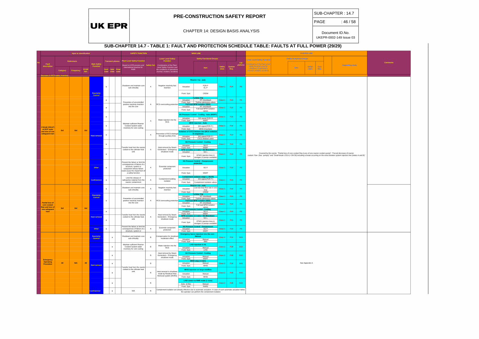
PRE-CONSTRUCTION SAFETY REPORT
CHAPTER 14: DESIGN BASIS ANALYSIS
SUB-CHAPTER : 14.7
PAGE : 46 / 58
Document ID.No. UKEPR-0002-149 Issue 03
SUB-CHAPTER 14.7 - TABLE 1: FAULT AND PROTECTION SCHEDULE TABLE: FAULTS AT FULL POWER (29/29)
C&I platform
Category Frequency PCSRRef.
Cont. state
Safe state
Final state
Actuation PZR PHL P
Front. Syst. CRDM
Actuation RT checkbackFront. Syst. Turbine admission valves
Actuation RT checkback
Front. Syst. Full load MFW isolation valves
Actuation SIS signal [PZR P]Front. Syst. MSRT
Actuation SIS signal [PZR P ]Front. Syst. MHSI (3 pumps)
Actuation SIS signal [PZR P ]Front. Syst. CVCS letdown valve
Actuation SG PFront. Syst. MSRT
Actuation SG L
Front. Syst. EFWS injection lines & storages (3 pumps available)
Actuation SG P
Front. Syst. MSRT
Actuation SIS signal [PZR P ]
Front. Syst. Containment isolation valves
Actuation Low-low loop flow rate in one loop
Front. Syst. CRDM
Actuation RT checkbackFront. Syst. Turbine admission valves
Actuation RT checkback
Front. Syst. Full load MFW isolation valves
Actuation SG PFront. Syst. MSRT
Actuation SG L
Front. Syst. EFWS injection lines & storages (3 pumps available)
Actuation SG PFront. Syst. MSRT
Actuation ManualFront. Syst. EBS
Actuation ManualFront. Syst. LHSI
Actuation ManualFront. Syst. MSRT
Actuation ManualFront. Syst. MHSI
Actuation Manual
Front. Syst. MHSI
Activ. & Elec ManualFront. Syst. RHRS
Confinement x N/A B
Isolation of CVCS letdown line (RCS isolation SI sequence)
Class 1
Class 1 F1A
F1A
F1A
F1A
x
SG Pressure Control - Cooling
Transfer heat from the reactor coolant to the ultimate heat
sinkA
Heat removal by Steam Generators - Emergency
shutdown mode
EFW actuation (1 train) + SG Blowdown
Prevention of uncontrolled positive reactivity insertion
into the core F1A PS
Heat removal
x
Class 1 F1A PS
Turbine TripClass 1
Full load MFW isolation (4SG)
Class 1
SG Pressure Control - Cooling
Class 1
Containment isolation stage 1 / RCPB
Class 1
SG Pressure Control - Overpressure protection
EFW actuation (1 train) + SG Blowdown
Class 1
Transfer heat from the reactor coolant to the ultimate heat
sink
PS
Shutdown and maintain core sub-criticality
Negative reactivity fast insertion
Reactor trip - auto
Containment building isolation
A RCS overcooling protection
PS
SAS
SAS
SAS
Syst Req.Item
PS
PS
PS
PS
Covered by the events “Partial loss of core coolant flow (Loss of one reactor coolant pump)”, “Forced decrease of reactor coolant flow (four pumps)” and “Small break LOCA (< DN 50) including a break occurring on the extra boration system injection line (states A and B)”
PS
PS
F1A
F1A
F1A
Emergency Operating Procedure All N/A
F1B
Prevention of RCS drainage through auxiliary lines
A
x
PS
PS
PS
PS
PS
Essential component protection
Heat removal by Steam Generators - Emergency
shutdown mode
A
All
Reactivity Control x
x
x
SAS
SAS
Class 2
Class 2
See Appendix A
SAS
Maintain sufficient Reactor Coolant System water
inventory for core cooling
Transfer heat from the reactor coolant to the ultimate heat
sink
Containment isolation are already effective due to automatic actuation. In case of such automatic actuation failed, the operator can perform the containment isolation
B
MHSI stop (1 train)
Heat removal in shutdown mode by Residual Heat
Removal system (RHRS)
F1B
F1B
F1B
B
B
SG Pressure Control - Cooling
MHSI injection on large miniflow
B
B
Water injection into the RCS
Heat removal by Steam Generators - Emergency
shutdown mode
LHSI injection in HL
LHSI switch to RHR mode (1 train)
SG Pressure Control - Cooling - Auto (MSRT)
MHSI injection - Auto
Turbine Trip
Shutdown and maintain core sub-criticality A
4 break (10cm²) at RCP seals
and loss of one safeguard train
Prevent the failure or limit the consequences of failure of a
structure, system or component whose failure
could cause the impairment of a safety function
xPrevention of uncontrolled positive reactivity insertion
into the corex
x
F1A
F1A
Class 1
PS
Class 1
Class 1
Class 1
No.
Input to classification SAFETY FUNCTION
Item
Fault description
ReferencesMain Safety
Function
Transient phases
MAIN LINE
Safety Functional Groups
CommentsPlant Level Safety Function
Based on EPR process and international practice for
PWR
Safety Cat.
Lower Level Safety Function
Combination of the Plant Level Safety Function and
the conditions of operations (normal, incident, accident)
DIVERSE LINE
Lower Level Safety Function
Combination of the Plant Level Safety Function and the conditions of operations
(normal, incident, accident)
Safety Functional Groups
Supporting study
tbd tbd tbd
Heat removal
tbd
Reactivity Control
tbd
Other
Heat removal
x
x
x
Other x
x
Confinement x
x
x
Decrease in RCS water inventory
Reactivity Control
tbd
Class 2
x
x
Shutdown and maintain core sub-criticality F1A
Essential component protection
SG Pressure Control - Overpressure Class 1 F1A
Class 2B Compensation for shutdown moderator effect
Emergency boron injection into the core - Manual
A
Safety class
System Req.
Safety class
A Full load MFW isolation (4SG)RCS overcooling protection
Negative reactivity fast insertion
Reactor trip - auto
Water injection into the RCS
A
F1A
Class 2
Class 2
Class 1 F1A
F1A
F1B
Class 1
Class 1
F1A
Maintain sufficient Reactor Coolant System water
inventory for core cooling
A
Partial loss of core coolant
flow and loss of one safeguard
train
Limit the release of radioactive material from the
reactor containmentA
Prevent the failure or limit the consequences of failure of a
structure, system or A
x
x
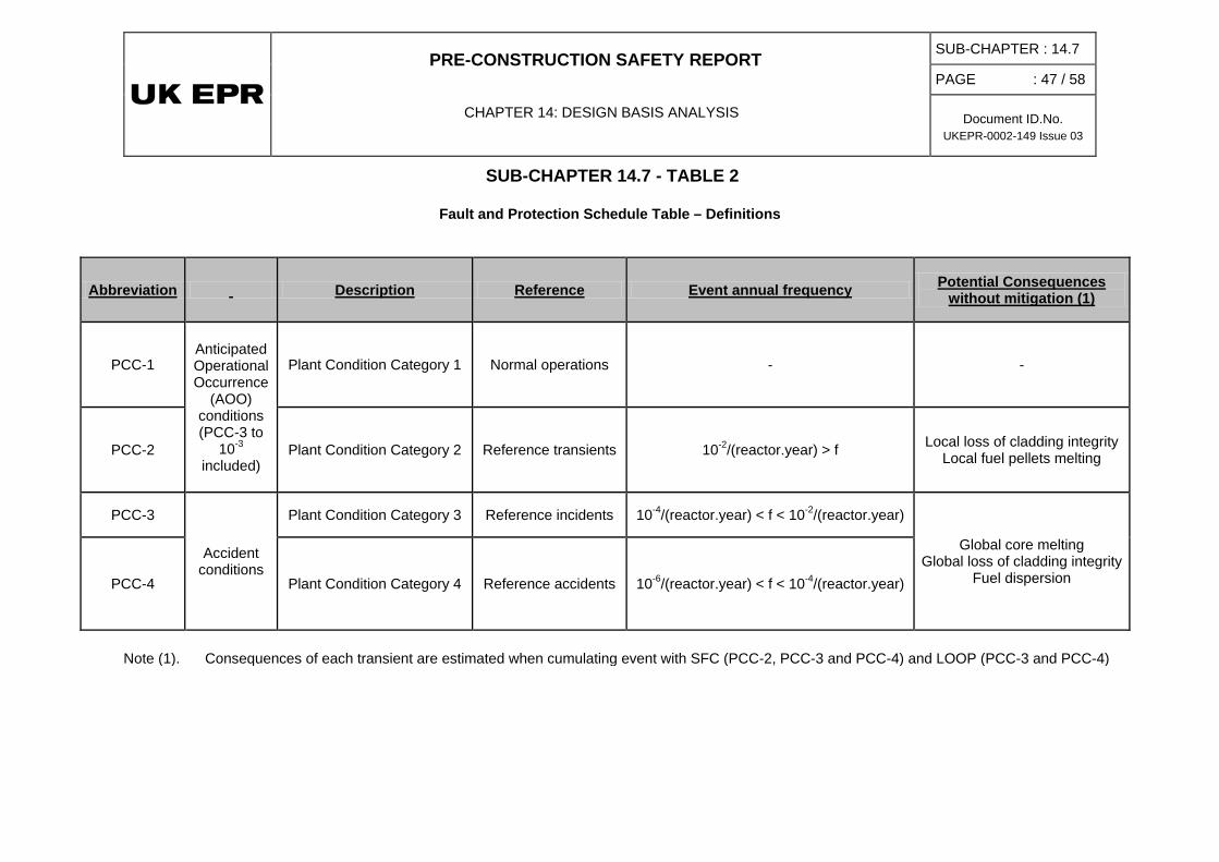
PRE-CONSTRUCTION SAFETY REPORT
CHAPTER 14: DESIGN BASIS ANALYSIS
SUB-CHAPTER : 14.7
PAGE : 47 / 58
Document ID.No. UKEPR-0002-149 Issue 03
SUB-CHAPTER 14.7 - TABLE 2
Fault and Protection Schedule Table – Definitions
Abbreviation Description Reference Event annual frequency Potential Consequences without mitigation (1)
PCC-1 Anticipated Operational Occurrence
(AOO) conditions (PCC-3 to
10-3 included)
Plant Condition Category 1 Normal operations - -
PCC-2 Plant Condition Category 2 Reference transients 10-2/(reactor.year) > f Local loss of cladding integrity Local fuel pellets melting
PCC-3
Accident conditions
Plant Condition Category 3 Reference incidents 10-4/(reactor.year) < f < 10-2/(reactor.year)
Global core melting Global loss of cladding integrity
Fuel dispersion PCC-4 Plant Condition Category 4 Reference accidents 10-6/(reactor.year) < f < 10-4/(reactor.year)
Note (1). Consequences of each transient are estimated when cumulating event with SFC (PCC-2, PCC-3 and PCC-4) and LOOP (PCC-3 and PCC-4)

PRE-CONSTRUCTION SAFETY REPORT
CHAPTER 14: DESIGN BASIS ANALYSIS
SUB-CHAPTER : 14.7
PAGE : 48 / 58
Document ID.No. UKEPR-0002-149 Issue 03
SUB-CHAPTER 14.7 - TABLE 3
Fault and Protection Schedule Table (Abbreviations)
Abbreviation Description ECS code
ACCU AccumulatorAO Axial OffsetATWS Anticipated Transient Whithout ScramCHRS Containment Heat Removal System EVUCont P High containment pressureCVCS Chemical And Volume Control System RCVDNBR Departure of Nucleate Boiling RatioEBS Extra Borating System RBSEDG Emergency Diesel Generator LHP/Q/R/SEFWS Emergency FeedWater System ASGFB Fuel BuildingFCD Fast CooldownFPCS Fuel Pool Cooling System PTRHCPL High Core Power LevelHL P Hot Leg PressureHLPD High Linear Power DensityLCO Limiting Condition of OperationLHSI Low Head Safety InjectionMFWS Main FeedWater System AREMFWS LL Main FeedWater System Low LoadMHSI Medium Head Safety InjectionMSB Main Steam Bypass GCTMSIV Main Steam Isolation ValveMSRIV Main Steam Relief Isolation ValveMSRT Main Steam Relief Train VDAMSSV Main Steam Safety ValveNF Neutron FluxPAS Process Automation SystemPCD Partial CooldownPDS Primary Depressurisation SystemPSV Pressuriser Safety ValvePT Partial TripPZR PresuriserPZR L Pressuriser LevelPZR P Pressuriser PressureRB Reactor BuildingRCP Reactor Coolant PumpRCS Reactor Coolant System RCPRT Reactor trip - autoSAS Safety Automation SystemSBO - DG Station BlackOut Diesel Generator LJP/SSG Steam GeneratorSG L Steam Generator LevelSG P Steam Generator PressureSIS Safety Injection System RISSSS Start-up and Shutdown System AADSSSS Stand Still Seal System DEATT Turbine Trip

PRE-CONSTRUCTION SAFETY REPORT
CHAPTER 14: DESIGN BASIS ANALYSIS
SUB-CHAPTER : 14.7
PAGE : 49 / 58
Document ID.No. UKEPR-0002-149 Issue 03
SUB-CHAPTER 14.7 - FIGURE 1
Primary pressure scale
MAX2
LCO
Nominal
RT → PROTECTION
Sequential rod drop → LIMITATION
PZR normal spray ON → CONTROL
Alarm
Control
LCO Alarm
ON-OFF heaters ON → CONTROL
RT → PROTECTION
RIS [SIS] actuation signal → PROTECTION
MIN2
MIN2
Opening of the 1st PSV → PROTECTION
Opening of the 2nd PSV → PROTECTION
Opening of the 3rd PSV → PROTECTION
MIN3
MIN3 RIS [SIS] actuation signal → RRC
RT → RRC
primary pressure

PRE-CONSTRUCTION SAFETY REPORT
CHAPTER 14: DESIGN BASIS ANALYSIS
SUB-CHAPTER : 14.7
PAGE : 50 / 58
Document ID.No. UKEPR-0002-149 Issue 03
SUB-CHAPTER 14.7 - FIGURE 2
SG level scale
MAX2
MAX1
LCO
PC → PROTECTION
RT ARE/AAD [MFWS/SSS] isolation in SGi
Alarm
Nominal Control
LCO Alarm
RT → PROTECTION
MIN1
MIN2 ASG [EFWS] actuation in SGi → PROTECTION
MIN2
MIN3
ASG [EFWS] actuation in SGi → RRC
RT → RRC
MAX2 VIV [MSIV] closure VDA [MSRT] setpoint increase in SGi
MAX1 ASG [EFWS] isolation in SGi → PROTECTION
SG level
MIN4 Reactor coolant pumps OFF → RRC
PROTECTION
PROTECTION
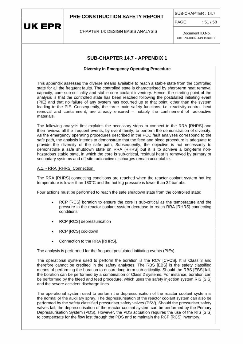
PRE-CONSTRUCTION SAFETY REPORT
CHAPTER 14: DESIGN BASIS ANALYSIS
SUB-CHAPTER : 14.7
PAGE : 51 / 58
Document ID.No. UKEPR-0002-149 Issue 03
SUB-CHAPTER 14.7 - APPENDIX 1
Diversity in Emergency Operating Procedure
This appendix assesses the diverse means available to reach a stable state from the controlled state for all the frequent faults. The controlled state is characterised by short-term heat removal capacity, core sub-criticality and stable core coolant inventory. Hence, the starting point of the analysis is that the controlled state has been reached following the postulated initiating event (PIE) and that no failure of any system has occurred up to that point, other than the system leading to the PIE. Consequently, the three main safety functions, i.e. reactivity control, heat removal and containment, are already ensured – notably the confinement of radioactive materials.
The following analysis first explains the necessary steps to connect to the RRA [RHRS] and then reviews all the frequent events, by event family, to perform the demonstration of diversity. As the emergency operating procedures described in the PCC fault analyses correspond to the safe path, the analysis intends to demonstrate that the feed and bleed procedure is adequate to provide the diversity of the safe path. Subsequently, the objective is not necessarily to demonstrate a safe shutdown state on RRA [RHRS] but it is to achieve a long-term non-hazardous stable state, in which the core is sub-critical, residual heat is removed by primary or secondary systems and off-site radioactive discharges remain acceptable.
The RRA [RHRS] connecting conditions are reached when the reactor coolant system hot leg temperature is lower than 180°C and the hot leg pressure is lower than 32 bar abs.
A.1. - RRA [RHRS] Connection
Four actions must be performed to reach the safe shutdown state from the controlled state:
• RCP [RCS] boration to ensure the core is sub-critical as the temperature and the pressure in the reactor coolant system decrease to reach RRA [RHRS] connecting conditions
• RCP [RCS] depressurisation
• RCP [RCS] cooldown
• Connection to the RRA [RHRS].
The analysis is performed for the frequent postulated initiating events (PIEs).
The operational system used to perform the boration is the RCV [CVCS]. It is Class 3 and therefore cannot be credited in the safety analyses. The RBS [EBS] is the safety classified means of performing the boration to ensure long-term sub-criticality. Should the RBS [EBS] fail, the boration can be performed by a combination of Class 2 systems. For instance, boration can be performed by the bleed and feed procedure, which uses the safety injection system RIS [SIS] and the severe accident discharge lines.
The operational system used to perform the depressurisation of the reactor coolant system is the normal or the auxiliary spray. The depressurisation of the reactor coolant system can also be performed by the safety classified pressuriser safety valves (PSV). Should the pressuriser safety valves fail, the depressurisation of the reactor coolant system can be performed by the Primary Depressurisation System (PDS). However, the PDS actuation requires the use of the RIS [SIS] to compensate for the flow lost through the PDS and to maintain the RCP [RCS] inventory.

PRE-CONSTRUCTION SAFETY REPORT
CHAPTER 14: DESIGN BASIS ANALYSIS
SUB-CHAPTER : 14.7
PAGE : 52 / 58
Document ID.No. UKEPR-0002-149 Issue 03
The cooldown of the reactor coolant system is performed during normal operation by the main steam bypass. The safety classified means to cooldown the reactor coolant system are the VDAs [MSRT]s. Should they fail, the bleed and feed procedure is actuated if the plant situation cannot be stabilised without the VDA [MSRT]s.
The connection to RRA [RHRS] can be performed only if the LHSI pumps are available, as one LHSI train is necessary to ensure the residual heat removal. Should the LHSI pumps not be available, the residual heat can be removed via the steam generators fed by the ASG [EFWS] and using the VDA [MSRT]s. MHSI may be required to maintain the reactor coolant system inventory.
The use of a diverse line may not always be necessary as the plant can be maintained in a controlled state. In particular, this is true in cases where:
• the automatic actions mitigate the PIE, or
• the integrity of the reactor coolant system and the secondary side are not impaired so that their inventories can be maintained after a controlled state is reached.
In these cases, the residual heat is removed by the secondary side in the long term because the steam generator water inventory is high and the reactor coolant system inventory is stable. Typically, the case of a spurious reactor trip falls into this category and is not analysed here any further.
The water volume in the ASG [EFWS] tanks provide sufficient inventory to ensure heat removal for 24 hours at hot shutdown. The ASG [EFWS] tanks can be refilled with water during that time, via the JAC (fire fighting water supply) system.
Frequent PIEs are analysed in the following sections in the light of the arguments provided above to demonstrate that a suitably classified diverse line exists to bring the plant to a long-term non-hazardous stable state.
A.2. - Frequent postulated initiating events
The postulated initiating event considered is:
A.2.1. - Increase in RCP [RCS] inventory
• RCV [CVCS] malfunction causing an increase in reactor coolant inventory
For this event, the diverse line is not necessary as the plant is in a stable state after mitigation of the initiating event by automatic actions, such as isolation of the RCV [CVCS] charging line on high pressuriser level.
In a similar manner to the situation after a reactor trip, the plant is stabilised and can subsequently be maintained in a long-term stable state.
The postulated initiating events considered are:
A.2.2. - Decrease in RCS inventory
• RCV [CVCS] malfunction causing decrease in reactor coolant inventory (state A)
• Inadvertent opening of a pressuriser safety valve

PRE-CONSTRUCTION SAFETY REPORT
CHAPTER 14: DESIGN BASIS ANALYSIS
SUB-CHAPTER : 14.7
PAGE : 53 / 58
Document ID.No. UKEPR-0002-149 Issue 03
• Small break (not greater than DN 50) including a break occurring on the Extra Boration System injection line (State A)
In the case of the RCV [CVCS] malfunction, the initiating event is mitigated by automatic actions, such as letdown isolation. The plant can remain in the hot shutdown condition in the long term, even in the event of failure of a system needed to reach the safe shutdown state. Moreover, reaching the RRA [RHRS] connecting conditions under these conditions is bounded by the SB LOCA case.
The case of the inadvertent opening of a pressuriser safety valve is similar to that of the SB LOCA in the phase from the controlled state to the safe shutdown state since at that stage, the PSV opening discharges steam in a similar manner to the SB LOCA case.
Therefore, the analysis is carried out for the case of the SB LOCA. The controlled state is reached when the MHSI flow compensates for the break flow rate and the RCP [RCS] inventory is stable. This ensures sufficient boration in the reactor coolant system. The table below presents the main and diverse lines of the different stages necessary to reach the safe shutdown state.
Main line Diverse line RCP [RCS] boration Emergency boron injection into
the core – Manual RIS [SIS] + PDS
RCP [RCS] cooldown SG Pressure Control – Cooling (VDA [MSRT])
Not necessary
RRA [RHRS] connection Stop MHSI (1 train) - manual No diversity RRA [RHRS] connection LHSI switch to RHR mode
(1 train) MHSI + EVU [CHRS] + VDA [MSRT] + ASG [EFWS]
Main and Diverse Lines to Reach Safe Shutdown State
The postulated initiating events considered are:
A.2.3. - Increase in heat removal
• Feedwater malfunction – causing a reduction in feedwater temperature
• Feedwater malfunction – causing an increase in feedwater temperature
• Excessive increase in steam flow
• Inadvertent opening of a SG relief train (state A)
For the feedwater malfunction events, as soon as the initiating event is mitigated, by reactor trip and full load main feedwater isolation, the plant is stabilised. The transfer to the safe shutdown state is bounded by the excessive increase in steam flow event.
The inadvertent opening of a SG relief train is mitigated by the closure of the main steam relief train control valve. The plant is then stabilised and heat can be removed by the remaining VDA [MSRT]s. The transfer to the safe shutdown state is performed in the same way as other events in which the integrity of the reactor coolant system or the steam lines is not impaired.
The table below presents the main and diverse lines used to reach a safe shutdown state.
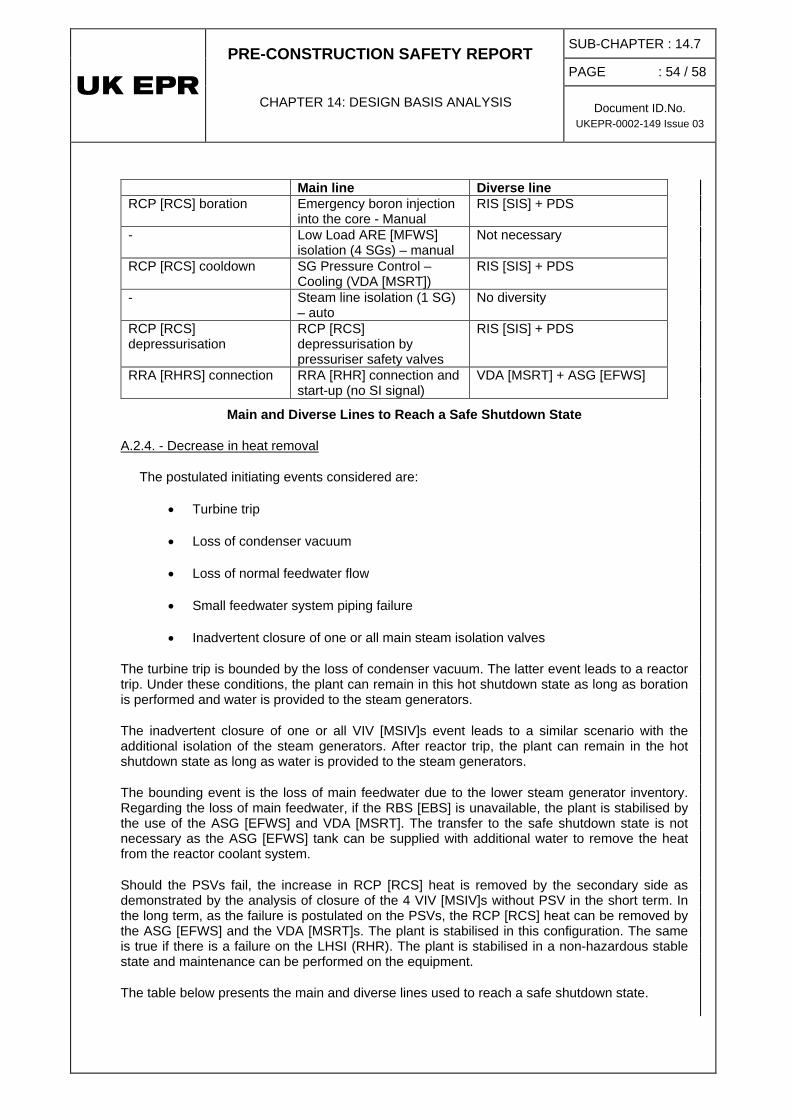
PRE-CONSTRUCTION SAFETY REPORT
CHAPTER 14: DESIGN BASIS ANALYSIS
SUB-CHAPTER : 14.7
PAGE : 54 / 58
Document ID.No. UKEPR-0002-149 Issue 03
Main line Diverse line RCP [RCS] boration Emergency boron injection
into the core - Manual RIS [SIS] + PDS
- Low Load ARE [MFWS] isolation (4 SGs) – manual
Not necessary
RCP [RCS] cooldown SG Pressure Control – Cooling (VDA [MSRT])
RIS [SIS] + PDS
- Steam line isolation (1 SG) – auto
No diversity
RCP [RCS] depressurisation
RCP [RCS] depressurisation by pressuriser safety valves
RIS [SIS] + PDS
RRA [RHRS] connection RRA [RHR] connection and start-up (no SI signal)
VDA [MSRT] + ASG [EFWS]
Main and Diverse Lines to Reach a Safe Shutdown State
The postulated initiating events considered are:
A.2.4. - Decrease in heat removal
• Turbine trip
• Loss of condenser vacuum
• Loss of normal feedwater flow
• Small feedwater system piping failure
• Inadvertent closure of one or all main steam isolation valves
The turbine trip is bounded by the loss of condenser vacuum. The latter event leads to a reactor trip. Under these conditions, the plant can remain in this hot shutdown state as long as boration is performed and water is provided to the steam generators.
The inadvertent closure of one or all VIV [MSIV]s event leads to a similar scenario with the additional isolation of the steam generators. After reactor trip, the plant can remain in the hot shutdown state as long as water is provided to the steam generators.
The bounding event is the loss of main feedwater due to the lower steam generator inventory. Regarding the loss of main feedwater, if the RBS [EBS] is unavailable, the plant is stabilised by the use of the ASG [EFWS] and VDA [MSRT]. The transfer to the safe shutdown state is not necessary as the ASG [EFWS] tank can be supplied with additional water to remove the heat from the reactor coolant system.
Should the PSVs fail, the increase in RCP [RCS] heat is removed by the secondary side as demonstrated by the analysis of closure of the 4 VIV [MSIV]s without PSV in the short term. In the long term, as the failure is postulated on the PSVs, the RCP [RCS] heat can be removed by the ASG [EFWS] and the VDA [MSRT]s. The plant is stabilised in this configuration. The same is true if there is a failure on the LHSI (RHR). The plant is stabilised in a non-hazardous stable state and maintenance can be performed on the equipment.
The table below presents the main and diverse lines used to reach a safe shutdown state.
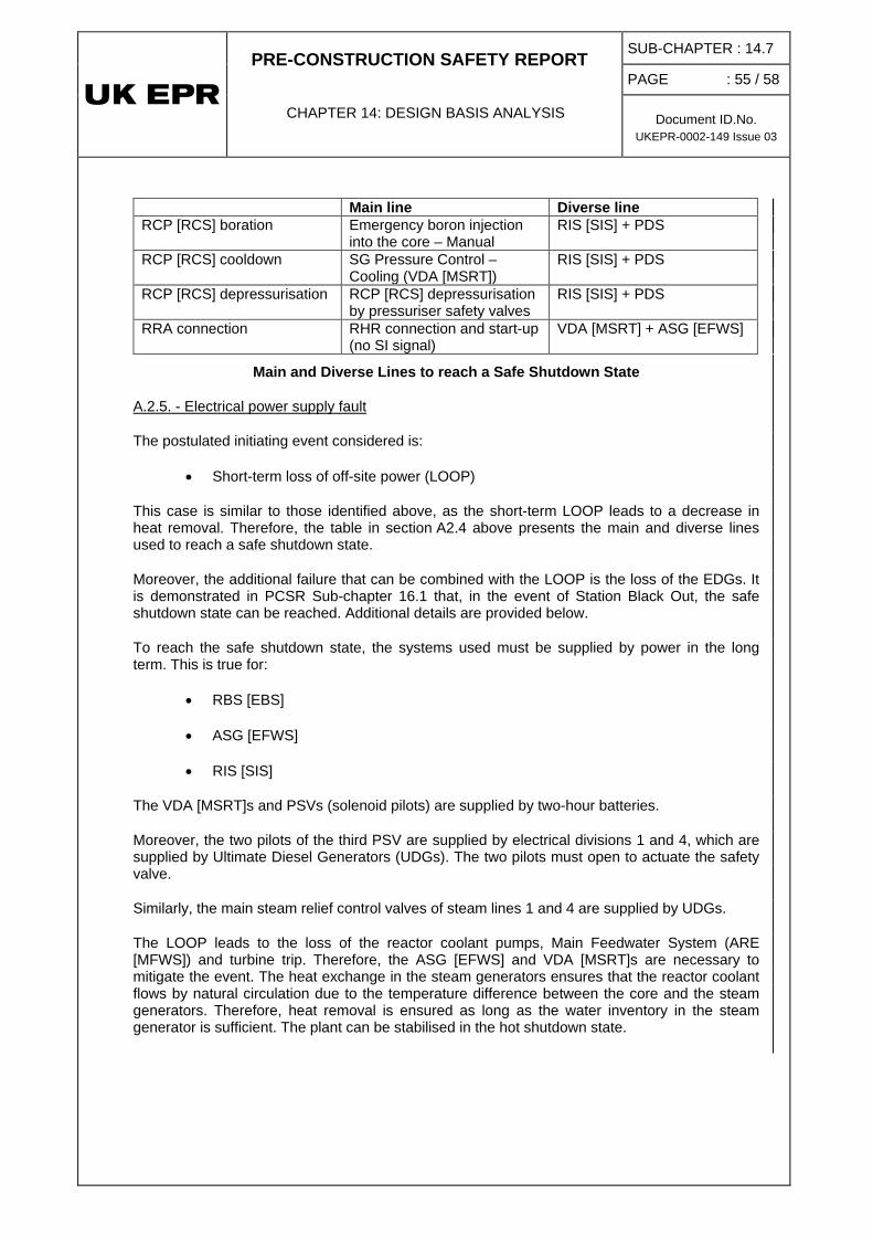
PRE-CONSTRUCTION SAFETY REPORT
CHAPTER 14: DESIGN BASIS ANALYSIS
SUB-CHAPTER : 14.7
PAGE : 55 / 58
Document ID.No. UKEPR-0002-149 Issue 03
Main line Diverse line RCP [RCS] boration Emergency boron injection
into the core – Manual RIS [SIS] + PDS
RCP [RCS] cooldown SG Pressure Control – Cooling (VDA [MSRT])
RIS [SIS] + PDS
RCP [RCS] depressurisation RCP [RCS] depressurisation by pressuriser safety valves
RIS [SIS] + PDS
RRA connection RHR connection and start-up (no SI signal)
VDA [MSRT] + ASG [EFWS]
Main and Diverse Lines to reach a Safe Shutdown State
The postulated initiating event considered is:
A.2.5. - Electrical power supply fault
• Short-term loss of off-site power (LOOP)
This case is similar to those identified above, as the short-term LOOP leads to a decrease in heat removal. Therefore, the table in section A2.4 above presents the main and diverse lines used to reach a safe shutdown state.
Moreover, the additional failure that can be combined with the LOOP is the loss of the EDGs. It is demonstrated in PCSR Sub-chapter 16.1 that, in the event of Station Black Out, the safe shutdown state can be reached. Additional details are provided below.
To reach the safe shutdown state, the systems used must be supplied by power in the long term. This is true for:
• RBS [EBS]
• ASG [EFWS]
• RIS [SIS]
The VDA [MSRT]s and PSVs (solenoid pilots) are supplied by two-hour batteries.
Moreover, the two pilots of the third PSV are supplied by electrical divisions 1 and 4, which are supplied by Ultimate Diesel Generators (UDGs). The two pilots must open to actuate the safety valve.
Similarly, the main steam relief control valves of steam lines 1 and 4 are supplied by UDGs.
The LOOP leads to the loss of the reactor coolant pumps, Main Feedwater System (ARE [MFWS]) and turbine trip. Therefore, the ASG [EFWS] and VDA [MSRT]s are necessary to mitigate the event. The heat exchange in the steam generators ensures that the reactor coolant flows by natural circulation due to the temperature difference between the core and the steam generators. Therefore, heat removal is ensured as long as the water inventory in the steam generator is sufficient. The plant can be stabilised in the hot shutdown state.

PRE-CONSTRUCTION SAFETY REPORT
CHAPTER 14: DESIGN BASIS ANALYSIS
SUB-CHAPTER : 14.7
PAGE : 56 / 58
Document ID.No. UKEPR-0002-149 Issue 03
In the case of steam generator tube rupture, the controlled state is reached when the leak is compensated by RCP [RCS] water make-up. In the fault studies, SGTR scenarios are demonstrated up to the end of the short-term phase where the SGTR leak flowrate is terminated by establishing a pressure balance between the RCP [RCS] and the affected SG (SGa).
A.2.6. - Steam generator tube rupture
The plant can remain in this condition in the long term, without further actions. Boration has been performed by the RIS [SIS], or the RCV [CVCS] if it is operational, which is more onerous because it prevents RIS [SIS] actuation.
The reactor coolant system inventory is stable due to the RCV [CVCS] or the RIS [SIS] and three steam generators contribute to the residual heat removal.
Radioactive releases are stabilised by isolation of the affected steam generator. If operational systems are available, they can be used to perform their functions. Therefore, the plant can remain in a long-term stable state. Cooldown occurs without intervention in the steam generators due to heat losses and causes the temperature of the reactor coolant system to reduce naturally, allowing the possibility of repairing the impaired systems.
The postulated initiating events considered are:
A.2.7. - Reactivity transients
• Uncontrolled RCCA bank withdrawal at power
• Uncontrolled RCCA bank withdrawal from Hot Zero Power (HZP)
• RCCA misalignment up to control rod drop
• Start-up of an inactive reactor coolant loop at an incorrect temperature
• RCV [CVCS] malfunction that results in a decrease in boron concentration in the reactor coolant
• Uncontrolled single RCCA withdrawal
These events lead to a reactor trip and do not impair the integrity of the reactor coolant system and the secondary side so that their inventories can be maintained after the controlled state is reached. Therefore, the non-hazardous stable state can be maintained in the long term.
The use of diverse means to reach the long-term non-hazardous stable state has been demonstrated, when necessary, for all the frequent initiating events. The feed and bleed procedure is used in most cases to ensure depressurisation, cooldown and boration. In the other cases, the plant can remain in a long-term non-hazardous stable state.
A.3. - Conclusions
Note: Class 1 manual actions with F1A architecture requirements are not required to reach the safe shutdown state. If they are provided to reach the safe shutdown state, it is due to their implementation in order to reach the controlled state in the following PCCs: steam line break, feedwater line break, piping failure on a main cooling train (states A to F).

PRE-CONSTRUCTION SAFETY REPORT
CHAPTER 14: DESIGN BASIS ANALYSIS
SUB-CHAPTER : 14.7
PAGE : 57 / 58
Document ID.No. UKEPR-0002-149 Issue 03
Note
: Since the initiating event frequencies for the "loss of support systems" events have not yet been determined, the diverse line for the Emergency Operating Procedures is not analysed in this revision of the Fault Schedule.
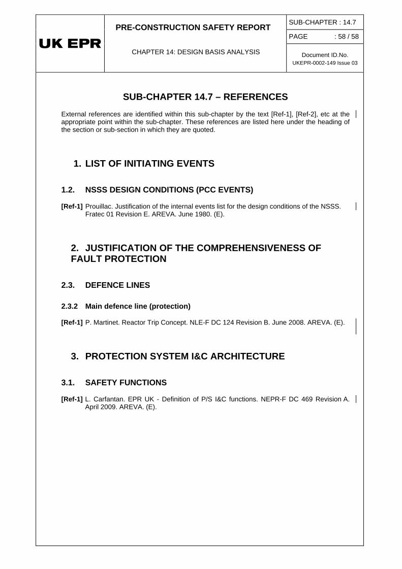
PRE-CONSTRUCTION SAFETY REPORT
CHAPTER 14: DESIGN BASIS ANALYSIS
SUB-CHAPTER : 14.7
PAGE : 58 / 58
Document ID.No. UKEPR-0002-149 Issue 03
SUB-CHAPTER 14.7 – REFERENCES
External references are identified within this sub-chapter by the text [Ref-1], [Ref-2], etc at the appropriate point within the sub-chapter. These references are listed here under the heading of the section or sub-section in which they are quoted.
1. LIST OF INITIATING EVENTS
1.2. NSSS DESIGN CONDITIONS (PCC EVENTS)
[Ref-1] Prouillac. Justification of the internal events list for the design conditions of the NSSS. Fratec 01 Revision E. AREVA. June 1980. (E).
2. JUSTIFICATION OF THE COMPREHENSIVENESS OF FAULT PROTECTION
2.3. DEFENCE LINES
2.3.2 Main defence line (protection)
[Ref-1] P. Martinet. Reactor Trip Concept. NLE-F DC 124 Revision B. June 2008. AREVA. (E).
3. PROTECTION SYSTEM I&C ARCHITECTURE
3.1. SAFETY FUNCTIONS
[Ref-1] L. Carfantan. EPR UK - Definition of P/S I&C functions. NEPR-F DC 469 Revision A. April 2009. AREVA. (E).


![PCSR – Sub-chapter 7.7 – I&C tools, development process ...epr-reactor.co.uk/ssmod/liblocal/docs/PCSR/Chapter 7...RRC-B SASand Process Information and Control System (MCP [PICS]).](https://static.fdocuments.net/doc/165x107/6120260e89bb271b4759af47/pcsr-a-sub-chapter-77-a-ic-tools-development-process-epr-7-rrc-b.jpg)