PCS Ferguson Opti-Flow Gas Lift System Gas Lift Troubleshooting Guide...
20
PCS Ferguson Opti-Flow ® Gas Lift System Gas Lift Troubleshooting Guide
Transcript of PCS Ferguson Opti-Flow Gas Lift System Gas Lift Troubleshooting Guide...

PCS Ferguson Opti-Flow® Gas Lift System
Gas Lift Troubleshooting Guide
2 Gas Lift Troubleshooting Guide
Table of Contents General Gas Lift System Problems ....................................................... 3 Inlet Problems ....................................................................................... 4 Outlet Problems .................................................................................... 5 Downhole Problems .............................................................................. 6 Tuning In the Well ................................................................................. 8 Troubleshooting Diagnostic Tools ....................................................... 10 Bottom Hole Pressure Test Procedure................................................ 11 Gas Lift Troubleshooting Check List ................................................... 12 Where to Install a 2-Pen Recorder ...................................................... 13 Interpretation of Pen Recorder Charts ................................................ 13 Continuous Flow Problems and Solutions ........................................... 14 Intermittent Flow Problems and Solutions ........................................... 17 Gas Lift Equipment Components ........................................................ 20
2

3 Gas Lift Troubleshooting Guide
General Gas Lift System Problems Problems with your gas lift system are often associated with three areas:
1. Inlet (surface) 2. Outlet (surface) 3. Downhole
More often than not, the problem can be found at the surface. Thoroughly explore all potential surface problems before incurring the expense of a wireline rig to investigate downhole causes. Also, keep in mind that poor optimization is most often caused by inaccurate gauge readings that can occur due to gauge malfunction or blockage. Always troubleshoot your well at the surface before you call a rig!
3

4 Gas Lift Troubleshooting Guide
Inlet Problems Low Casing Pressure Check the choke to see if it is plugged, frozen or too small. Also, verify the gauge readings to be sure the problem is real. A check of gas volume being injected will help you rule out low casing pressure due to a hole in the tubing or cutout valve. If the choke is frozen, the problem can often be remedied by continuous injection of methanol in the gas lift gas. High Casing Pressure Check the gas injection volume. If high casing pressure is accompanied by high injection gas volumes, the choke may be too large, causing the upper valves to re-open. If high casing pressure is accompanied by low injection gas volumes, the operating valve may be partially plugged. This may also indicate that higher than anticipated temperatures are raising the set pressures of pressure operated valves. Also, high tubing pressure may be reducing the differential between the tubing and casing. In this case, remove the flowline choke or restriction. Low Gas Usage Ensure the gas lift line valve is fully open and that the casing choke is not too small, frozen or plugged. Verify the available operating pressure is in the range required for valve operation. Also, determine if the gas volume is being delivered to the desired well or if nearby wells—particularly intermittent wells—may be robbing the system. A higher than anticipated production rate and the resulting higher temperature may also cause the valve set pressure increase and consequently restrict the gas input. Excessive Gas Usage Check the casing pressure. The casing choke may be too large or the casing pressure too excessive. Both may cause upper pressure valves to re-open. If excessive gas volume is accompanied by low casing pressure, a tubing leak or cut-out valve may be to blame. Intermitter Problems Ensure the intermitter has not stopped, whether it is a manual (wind-up) or battery-operated model. Intermitter cycle time should be set to achieve maximum fluid volume from the minimum number of cycles. Injection duration should then be adjusted to minimize “tail gas.” Avoid choking an intermitter unless absolutely necessary. In most gas lift systems, opening the intermitter reduces the system pressure. In this case, it may be possible to reduce the pressure fluctuation by placing a small choke in parallel with the intermitter or using the annular space of nearby dead wells as volume chambers. Wells intermitting in excess of 200 BFPD should be evaluated for constant flow application. Less than one barrel per cycle is probably an indication that the well is cycling too rapidly. Choke Sizing The design gas liquid ratio can often give an indication of the choke size to use as a starting point. Faulty Gauges Check the wellhead casing and tubing pressures with a calibrated gauge. Inaccurate gauges can cause false indications of high or low casing pressures.
Changes in casing pressure and gas volume typically indicate a problem with the inlet.
4
5 Gas Lift Troubleshooting Guide
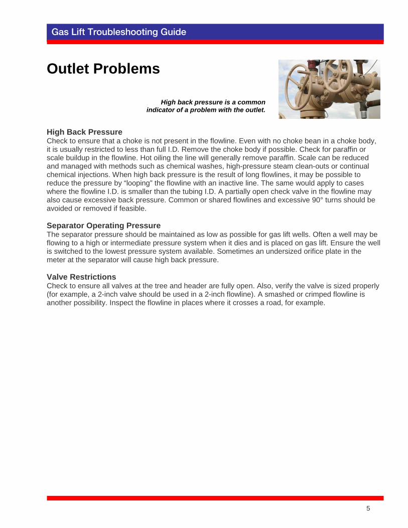
Outlet Problems High Back Pressure Check to ensure that a choke is not present in the flowline. Even with no choke bean in a choke body, it is usually restricted to less than full I.D. Remove the choke body if possible. Check for paraffin or scale buildup in the flowline. Hot oiling the line will generally remove paraffin. Scale can be reduced and managed with methods such as chemical washes, high-pressure steam clean-outs or continual chemical injections. When high back pressure is the result of long flowlines, it may be possible to reduce the pressure by “looping” the flowline with an inactive line. The same would apply to cases where the flowline I.D. is smaller than the tubing I.D. A partially open check valve in the flowline may also cause excessive back pressure. Common or shared flowlines and excessive 90° turns should be avoided or removed if feasible. Separator Operating Pressure The separator pressure should be maintained as low as possible for gas lift wells. Often a well may be flowing to a high or intermediate pressure system when it dies and is placed on gas lift. Ensure the well is switched to the lowest pressure system available. Sometimes an undersized orifice plate in the meter at the separator will cause high back pressure. Valve Restrictions Check to ensure all valves at the tree and header are fully open. Also, verify the valve is sized properly (for example, a 2-inch valve should be used in a 2-inch flowline). A smashed or crimped flowline is another possibility. Inspect the flowline in places where it crosses a road, for example.
High back pressure is a common indicator of a problem with the outlet.
5
6 Gas Lift Troubleshooting Guide
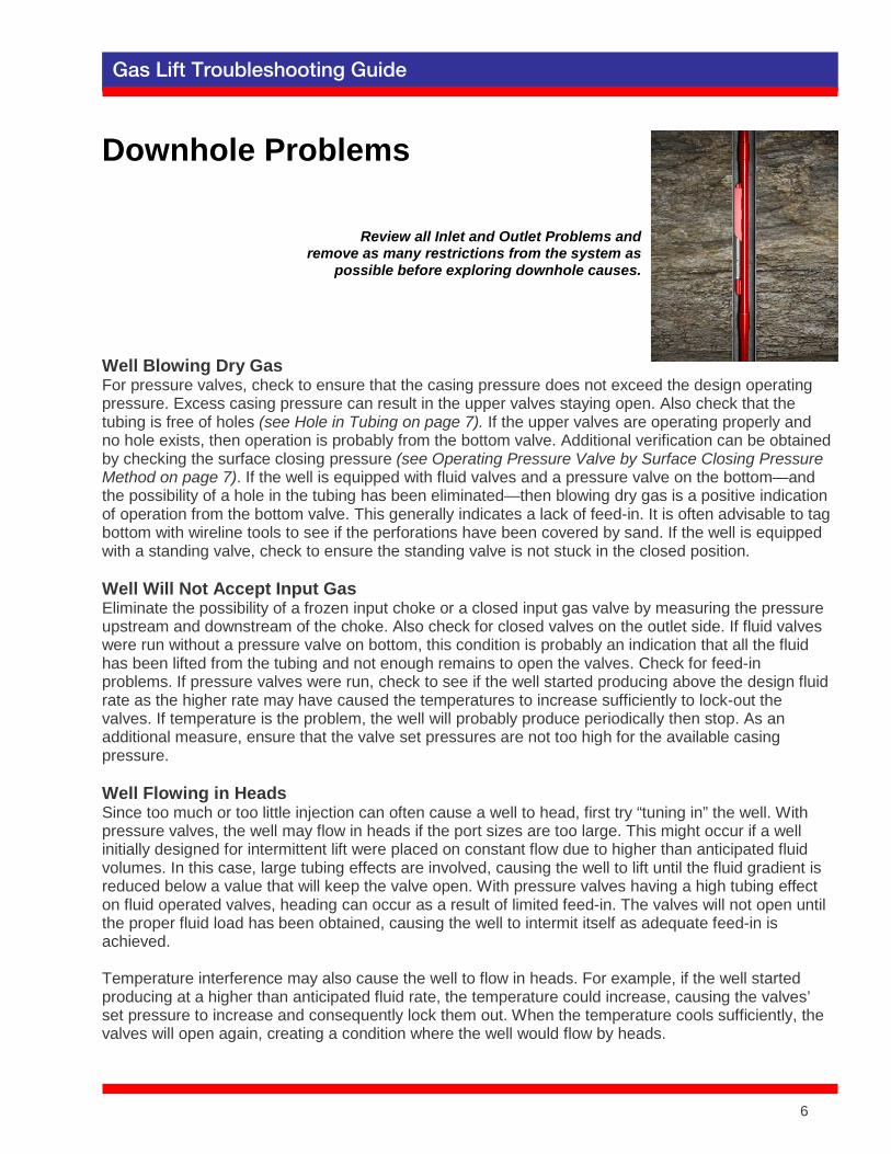
Downhole Problems Well Blowing Dry Gas For pressure valves, check to ensure that the casing pressure does not exceed the design operating pressure. Excess casing pressure can result in the upper valves staying open. Also check that the tubing is free of holes (see Hole in Tubing on page 7). If the upper valves are operating properly and no hole exists, then operation is probably from the bottom valve. Additional verification can be obtained by checking the surface closing pressure (see Operating Pressure Valve by Surface Closing Pressure Method on page 7). If the well is equipped with fluid valves and a pressure valve on the bottom—and the possibility of a hole in the tubing has been eliminated—then blowing dry gas is a positive indication of operation from the bottom valve. This generally indicates a lack of feed-in. It is often advisable to tag bottom with wireline tools to see if the perforations have been covered by sand. If the well is equipped with a standing valve, check to ensure the standing valve is not stuck in the closed position. Well Will Not Accept Input Gas Eliminate the possibility of a frozen input choke or a closed input gas valve by measuring the pressure upstream and downstream of the choke. Also check for closed valves on the outlet side. If fluid valves were run without a pressure valve on bottom, this condition is probably an indication that all the fluid has been lifted from the tubing and not enough remains to open the valves. Check for feed-in problems. If pressure valves were run, check to see if the well started producing above the design fluid rate as the higher rate may have caused the temperatures to increase sufficiently to lock-out the valves. If temperature is the problem, the well will probably produce periodically then stop. As an additional measure, ensure that the valve set pressures are not too high for the available casing pressure. Well Flowing in Heads Since too much or too little injection can often cause a well to head, first try “tuning in” the well. With pressure valves, the well may flow in heads if the port sizes are too large. This might occur if a well initially designed for intermittent lift were placed on constant flow due to higher than anticipated fluid volumes. In this case, large tubing effects are involved, causing the well to lift until the fluid gradient is reduced below a value that will keep the valve open. With pressure valves having a high tubing effect on fluid operated valves, heading can occur as a result of limited feed-in. The valves will not open until the proper fluid load has been obtained, causing the well to intermit itself as adequate feed-in is achieved. Temperature interference may also cause the well to flow in heads. For example, if the well started producing at a higher than anticipated fluid rate, the temperature could increase, causing the valves’ set pressure to increase and consequently lock them out. When the temperature cools sufficiently, the valves will open again, creating a condition where the well would flow by heads.
Review all Inlet and Outlet Problems and remove as many restrictions from the system as
possible before exploring downhole causes.
6
7 Gas Lift Troubleshooting Guide
Downhole Problems continued… Installation Stymied and Well Will Not Unload Try applying injection gas pressure to the top of the fluid column (usually with a jumper line). Often, this will drive some of the fluid column back into the formation, reducing the height of the fluid column being lifted and allowing unloading with the available lift pressure. This condition generally occurs when the fluid column is heavier than the available lift pressure. The check valves prevent this fluid from being displaced back into the casing. For fluid operated valves, “rocking” the well in this fashion will often open an upper valve and permit the unloading operation to continue. Sometimes, a well can be “swabbed” to allow unloading to a deeper valve. Also ensure that the wellhead back pressure is not excessive, or that the fluid used to kill the well for workover was not too heavy for the design. Hole in Tubing Indicators of a hole in the tubing include abnormally low casing pressure and excessively high gas usage. A hole in the tubing can be confirmed by the following procedure: Equalize the tubing pressure and casing pressure by closing the wing valve with the gas lift gas on. After the pressures are equalized, shut off the gas input valve and rapidly bleed-off the casing
pressure. If the tubing pressure bleeds as the casing pressure drops, then a hole is indicated. The tubing pressure will hold if no hole is present since both the check valves and gas lift valves will be in the closed position as the casing pressure bleeds to zero. A packer leak may also cause symptoms similar to a hole in the tubing. Operating Pressure Valve by Surface Closing Pressure Method A pressure operated valve will inject gas until the casing pressure drops to the closing pressure of the valve. As such, the operating valve’s surface closing pressure can often be estimated by shutting off the input gas and noting the pressure at which the casing holds. This pressure is the same as the closing pressure of the valve. Closing pressure analysis assumes two things: 1) the tubing pressure to be zero and 2) there is single point injection. These assumptions limit the accuracy of this method since the tubing pressure at each valve is never zero, and multipoint injection may be occurring. Nonetheless, this method can be helpful when used in combination with other data to bracket the operating valve. Valve Hung Open This case can be identified when casing pressure bleeds below the surface closing pressure of any valve in the hole, and it has been determined that a hole in the tubing is not the cause. Try shutting the wing valve and allowing the casing pressure to build up as high as possible, then open the wing valve rapidly. This action will create high differential pressures across the valve seat, removing any matter that may be holding it open. Repeat the process several times if required. In some cases, valves are held open by salt deposition. Pumping several barrels of fresh water into the casing will solve the problem. If all other potential causes have been eliminated, a cut out or flat valve may be the cause. Valve Spacing Too Wide Try “rocking” the well as indicated when the well will not unload. This may allow injection to work down to lower valves. If a high pressure gas well is nearby, using the pressure from this well may facilitate unloading. If the problem is severe, you may need to re-space the valves, install a pack off gas lift valve, or shoot an orifice into the tubing to achieve a new point of injection.
7
8 Gas Lift Troubleshooting Guide
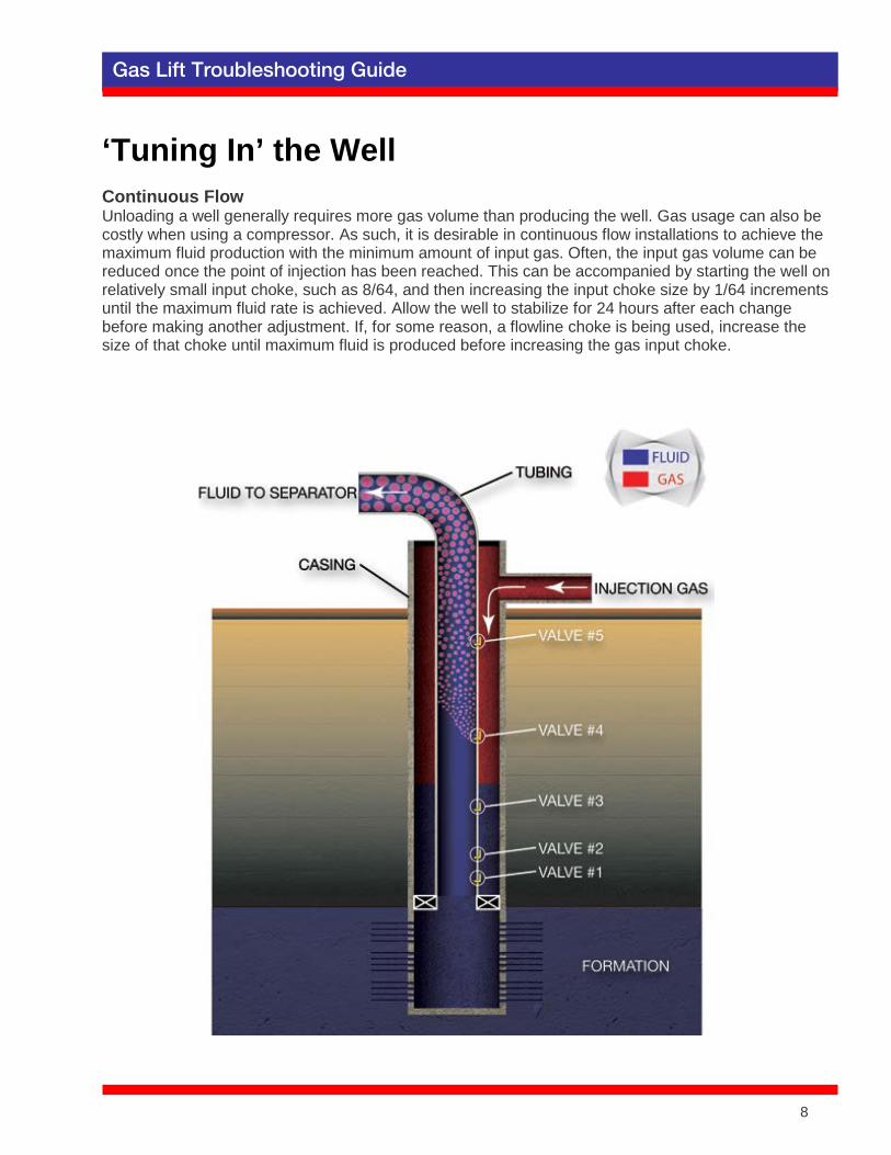
‘Tuning In’ the Well Continuous Flow Unloading a well generally requires more gas volume than producing the well. Gas usage can also be costly when using a compressor. As such, it is desirable in continuous flow installations to achieve the maximum fluid production with the minimum amount of input gas. Often, the input gas volume can be reduced once the point of injection has been reached. This can be accompanied by starting the well on relatively small input choke, such as 8/64, and then increasing the input choke size by 1/64 increments until the maximum fluid rate is achieved. Allow the well to stabilize for 24 hours after each change before making another adjustment. If, for some reason, a flowline choke is being used, increase the size of that choke until maximum fluid is produced before increasing the gas input choke.
8
9 Gas Lift Troubleshooting Guide
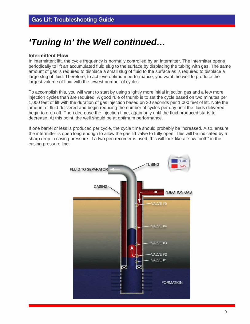
‘Tuning In’ the Well continued… Intermittent Flow In intermittent lift, the cycle frequency is normally controlled by an intermitter. The intermitter opens periodically to lift an accumulated fluid slug to the surface by displacing the tubing with gas. The same amount of gas is required to displace a small slug of fluid to the surface as is required to displace a large slug of fluid. Therefore, to achieve optimum performance, you want the well to produce the largest volume of fluid with the fewest number of cycles. To accomplish this, you will want to start by using slightly more initial injection gas and a few more injection cycles than are required. A good rule of thumb is to set the cycle based on two minutes per 1,000 feet of lift with the duration of gas injection based on 30 seconds per 1,000 feet of lift. Note the amount of fluid delivered and begin reducing the number of cycles per day until the fluids delivered begin to drop off. Then decrease the injection time, again only until the fluid produced starts to decrease. At this point, the well should be at optimum performance. If one barrel or less is produced per cycle, the cycle time should probably be increased. Also, ensure the intermitter is open long enough to allow the gas lift valve to fully open. This will be indicated by a sharp drop in casing pressure. If a two pen recorder is used, this will look like a “saw tooth” in the casing pressure line.
9

10 Gas Lift Troubleshooting Guide
Troubleshooting Diagnostic Tools Calculations Determining the operating valve is one method of checking gas lift performance. You can do this by calculating the surface closing pressure or comparing the valve opening pressures with the opening forces that exist at each downhole valve given the operating, tubing and casing pressures, the temperatures, etc. Because of the data used, this method may not be as accurate as a flowing pressure survey. However, it can still be a valuable tool in determining the need for more expensive diagnostics. Flowing Pressure Survey A pressure bomb is run in the well under flowing conditions. A no-blow tool is run with the pressure bomb tools to prevent them from being “blown up the hole.” The no-blow tool is equipped with “dogs” or slips which are activated by sudden movement up the hole. The bomb is stopped at each gas lift valve for a period of time, and records the pressures at each valve. From this information, the exact point of injection can be determined, as well as the actual flowing bottom hole pressure. A flowing pressure survey is the most accurate way to determine a gas lift well’s performance, provided that an accurate well test is run in conjunction with the survey. Well Sounding Devices The fluid level in the annulus of a gas lift well may give an indication of the depth of lift. This method utilizes the principle of sound waves to determine the depth of the fluid level in the annulus. Acoustic devices are fairly inexpensive when compared to flowing pressure surveys. It should be noted that for wells with packers, it is possible for injection to occur through a deeper valve while unloading, then return to a higher valve up the tubing. In this case, the resulting fluid level in the annulus will be below the actual point of operation. Tagging Fluid Level Tagging the fluid level in a well with wireline tools may give an estimation of the operating valve, but it is a questionable method and subject to several limitations. Fluid feed-in will often raise the fluid level before the wireline tools can get down the hole. In addition, fluid fallback will always occur after the gas lift gas has been shut off. Both of these factors will cause the observed fluid level to be above the operating valve. Care should be taken to ensure that the input gas valve was closed prior to closing the wing valve or the gas pressure will drive the fluid back down the hole and below the point of operation. Two Pen Recorder Charts To calculate the operating valve, it is necessary to have accurate tubing and casing pressure data. Two pen recorder charts give a continuous recording of these pressures and can be quite useful if accompanied by an accurate well test. The two pen recorder charts can be used to optimize surface controls and locate surface problems, as well as identify downhole problems.
10
11 Gas Lift Troubleshooting Guide
Bottom Hole Pressure Test Procedure The following details how to conduct flowing bottom hole pressure tests in cases where the well is equipped with gas lift valves. A. Intermitting Gas Lift Wells
1. Install crown valve on well if necessary and flow the well to the test separator for 24 hours so a
stabilized production rate is known. (Test facilities should duplicate as nearly as possible normal production facilities).
2. Put well on test before running bottom hole pressure. Test should run a minimum of 6 hours.
Test information, two pen recorder charts and separator chart should be sent in with pressure traverse.
3. Pressure bomb must be equipped with one, preferably two “No-Blow” tools. Use a small
diameter bomb. 4. Install lubricator and pressure recording bomb. Let well cycle one time with the bomb just below
the lubricator to record the wellhead pressure and to ensure that the “No-Blow” tools are working. Run bomb, making stops 15 feet below each gas lift valve. Be sure to record a maximum and minimum pressure at each gas lift valve. Do not shut well in while rigging up or recording flowing pressures in tubing.
5. Leave bomb on bottom for at least two complete intermitting cycles.
B. Continuous Flow Gas Lift Wells
1. Install crown valve on well if necessary and flow the well to the test separator for 24 hours so a
stabilized production rate is known. (Test facilities should duplicate as nearly as possible normal production facilities).
2. Put well on test before running bottom hole pressure. Test should run a minimum of 6 hours.
Gas and fluid test, two pen recorder chart and separator chart should be sent in with pressure traverse.
3. Pressure bomb must be equipped with one, preferably two “No-Blow” tools. Use a small
diameter bomb. 4. Install lubricator and pressure recording bomb. Make first stop in lubricator to record wellhead
pressure. Run bomb, making stops 15 feet below each gas lift valve for 3 minutes. (Do not shut well in while rigging up or recording flowing pressures in tubing).
5. Leave bomb on bottom for at least 30 minutes, preferably at the same depth that the last static
bottom hole pressure was taken. 6. Casing pressure should be measured with a dead weight tester or recently calibrated two pen
recorder.
11
12 Gas Lift Troubleshooting Guide
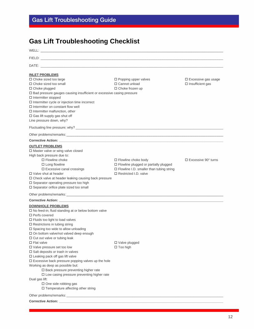
Gas Lift Troubleshooting Checklist WELL: ___________________________________________________________________________________________________
FIELD: ___________________________________________________________________________________________________
DATE: ___________________________________________________________________________________________________ INLET PROBLEMS Choke sized too large Popping upper valves Excessive gas usage Choke sized too small Cannot unload Insufficient gas Choke plugged Choke frozen up Bad pressure gauges causing insufficient or excessive casing pressure Intermitter stopped Intermitter cycle or injection time incorrect Intermitter on constant flow well Intermitter malfunction, other Gas lift supply gas shut off Line pressure down, why?
Fluctuating line pressure; why? ________________________________________________________________________________
Other problems/remarks: _____________________________________________________________________________________
Corrective Action: _________________________________________________________________________________________ OUTLET PROBLEMS Master valve or wing valve closed High back pressure due to: Flowline choke Flowline choke body Excessive 90° turns Long flowline Flowline plugged or partially plugged Excessive canal crossings Flowline I.D. smaller than tubing string Valve shut at header Restricted I.D. valve Check valve at header leaking causing back pressure Separator operating pressure too high Separator orifice plate sized too small
Other problems/remarks: _____________________________________________________________________________________
Corrective Action: _________________________________________________________________________________________ DOWNHOLE PROBLEMS No feed-in; fluid standing at or below bottom valve Perfs covered Fluids too light to load valves Restrictions in tubing string Spacing too wide to allow unloading On bottom valve/not valved deep enough Cut out valve or tubing leak Flat valve Valve plugged Valve pressure set too low Too high Salt deposits or trash in valves Leaking pack off gas lift valve Excessive back pressure popping valves up the hole Working as deep as possible but: Back pressure preventing higher rate Low casing pressure preventing higher rate Dual gas lift: One side robbing gas Temperature affecting other string
Other problems/remarks: _____________________________________________________________________________________
Corrective Action: _________________________________________________________________________________________
12
13 Gas Lift Troubleshooting Guide
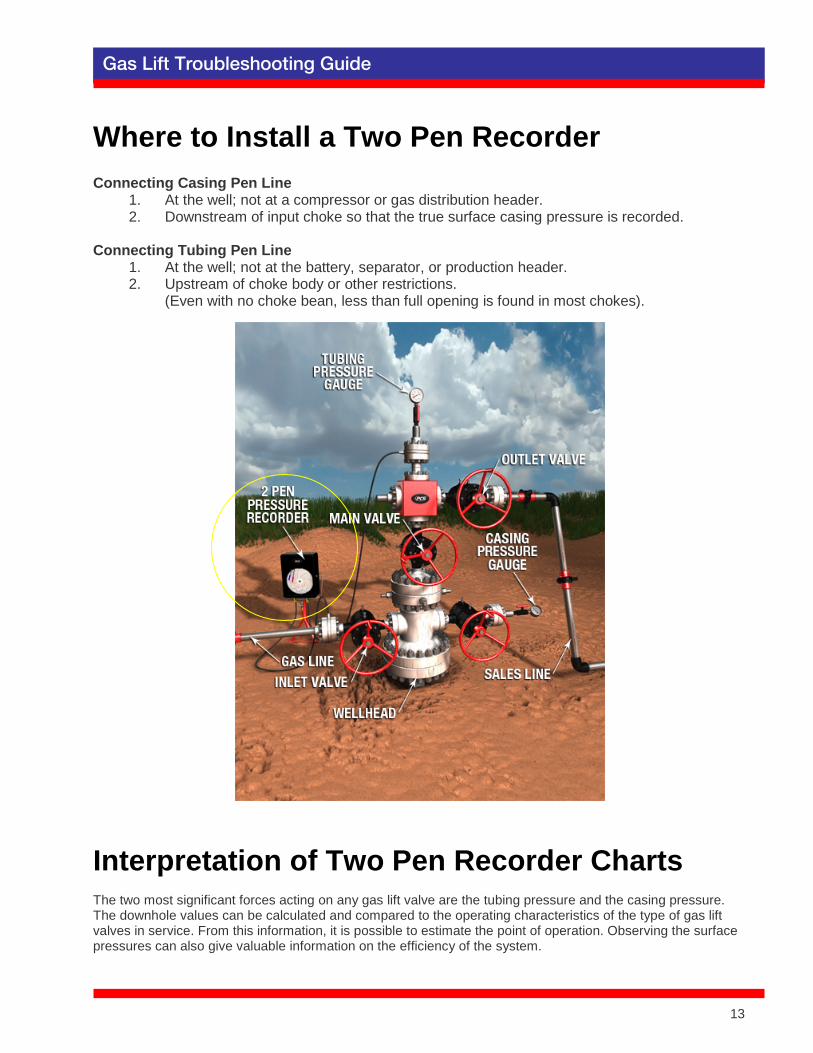
Where to Install a Two Pen Recorder Connecting Casing Pen Line
1. At the well; not at a compressor or gas distribution header. 2. Downstream of input choke so that the true surface casing pressure is recorded.
Connecting Tubing Pen Line
1. At the well; not at the battery, separator, or production header. 2. Upstream of choke body or other restrictions.
(Even with no choke bean, less than full opening is found in most chokes).
Interpretation of Two Pen Recorder Charts The two most significant forces acting on any gas lift valve are the tubing pressure and the casing pressure. The downhole values can be calculated and compared to the operating characteristics of the type of gas lift valves in service. From this information, it is possible to estimate the point of operation. Observing the surface pressures can also give valuable information on the efficiency of the system.
13
14 Gas Lift Troubleshooting Guide
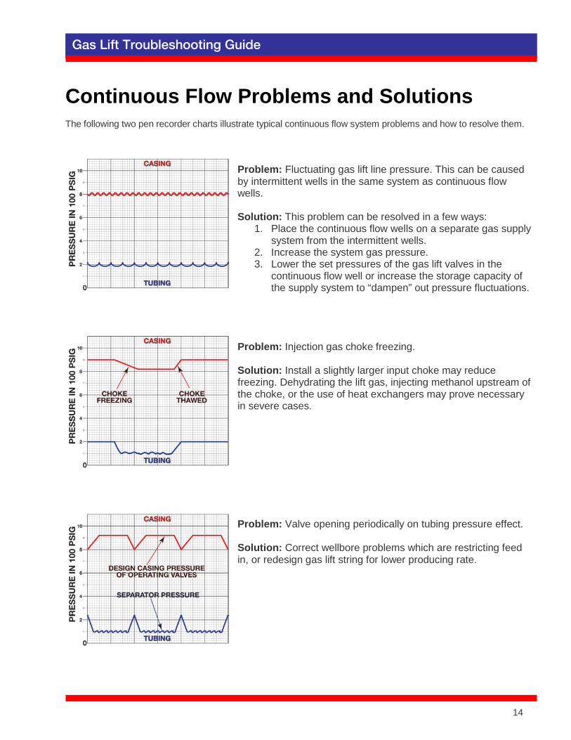
Continuous Flow Problems and Solutions The following two pen recorder charts illustrate typical continuous flow system problems and how to resolve them.
Problem: Fluctuating gas lift line pressure. This can be caused by intermittent wells in the same system as continuous flow wells. Solution: This problem can be resolved in a few ways:
1. Place the continuous flow wells on a separate gas supply system from the intermittent wells.
2. Increase the system gas pressure. 3. Lower the set pressures of the gas lift valves in the
continuous flow well or increase the storage capacity of the supply system to “dampen” out pressure fluctuations.
Problem: Injection gas choke freezing. Solution: Install a slightly larger input choke may reduce freezing. Dehydrating the lift gas, injecting methanol upstream of the choke, or the use of heat exchangers may prove necessary in severe cases.
Problem: Valve opening periodically on tubing pressure effect. Solution: Correct wellbore problems which are restricting feed in, or redesign gas lift string for lower producing rate.
14
15 Gas Lift Troubleshooting Guide
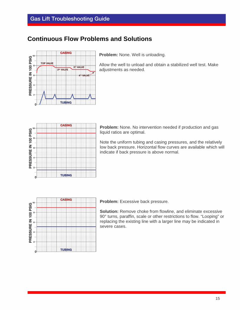
Continuous Flow Problems and Solutions
Problem: None. Well is unloading. Allow the well to unload and obtain a stabilized well test. Make adjustments as needed.
Problem: None. No intervention needed if production and gas liquid ratios are optimal. Note the uniform tubing and casing pressures, and the relatively low back pressure. Horizontal flow curves are available which will indicate if back pressure is above normal.
Problem: Excessive back pressure. Solution: Remove choke from flowline, and eliminate excessive 90° turns, paraffin, scale or other restrictions to flow. “Looping” or replacing the existing line with a larger line may be indicated in severe cases.
15
16 Gas Lift Troubleshooting Guide
Continuous Flow Problems and Solutions
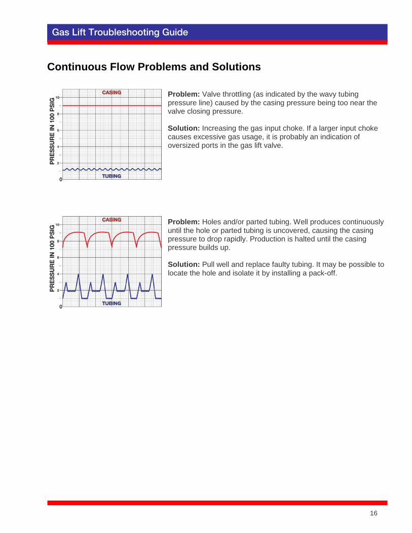
Problem: Valve throttling (as indicated by the wavy tubing pressure line) caused by the casing pressure being too near the valve closing pressure. Solution: Increasing the gas input choke. If a larger input choke causes excessive gas usage, it is probably an indication of oversized ports in the gas lift valve.
Problem: Holes and/or parted tubing. Well produces continuously until the hole or parted tubing is uncovered, causing the casing pressure to drop rapidly. Production is halted until the casing pressure builds up. Solution: Pull well and replace faulty tubing. It may be possible to locate the hole and isolate it by installing a pack-off.
16

17 Gas Lift Troubleshooting Guide
Intermittent Flow Problems and Solutions The following two pen recorder charts illustrate typical intermittent flow system problems and how to resolve them.
Problem: None. Good operation. Rapid build-up and draw down of casing pressure with constant pressure between cycles indicates good valve operation. Thin sharp spikes in tubing pressure indicate good slug recovery.
Problem: Leaking valve as indicated by casing pressure drawdown between cycles. Solution: Attempt to clear trash (which may be preventing valve closure) from valve seat by means described in downhole problems section on page 6. If that fails it may be necessary to pull the valves if the problem causes significant loss of production or excess gas usage.
Problem: Leak in tubing string as indicated by relatively flat tubing pressure and excessive gas usage. Lack of tubing spikes indicates no valve action at all. Solution: Pull and replace defective tubing.
17
18 Gas Lift Troubleshooting Guide
Intermittent Flow Problems and Solutions
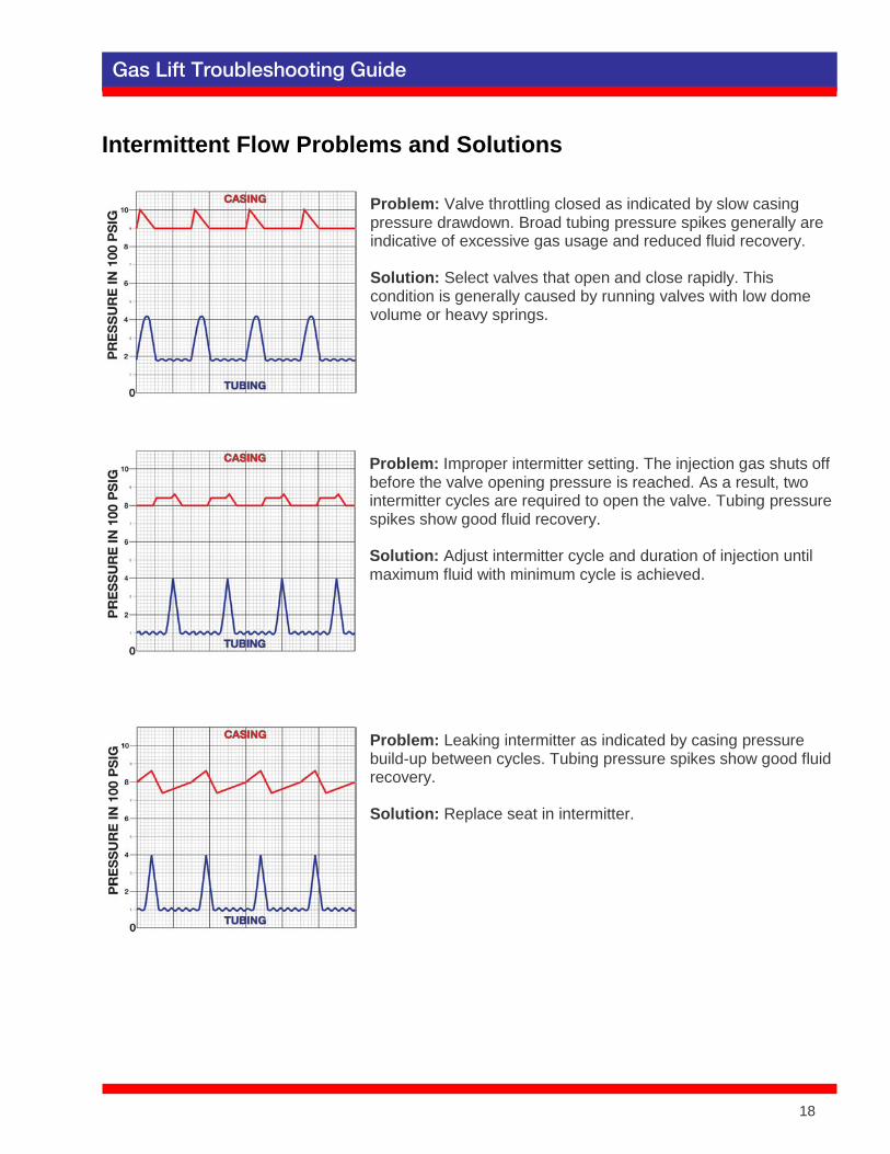
Problem: Valve throttling closed as indicated by slow casing pressure drawdown. Broad tubing pressure spikes generally are indicative of excessive gas usage and reduced fluid recovery. Solution: Select valves that open and close rapidly. This condition is generally caused by running valves with low dome volume or heavy springs.
Problem: Improper intermitter setting. The injection gas shuts off before the valve opening pressure is reached. As a result, two intermitter cycles are required to open the valve. Tubing pressure spikes show good fluid recovery. Solution: Adjust intermitter cycle and duration of injection until maximum fluid with minimum cycle is achieved.
Problem: Leaking intermitter as indicated by casing pressure build-up between cycles. Tubing pressure spikes show good fluid recovery. Solution: Replace seat in intermitter.
18

19 Gas Lift Troubleshooting Guide
Intermittent Flow Problems and Solutions
Problem: None. Well intermitting with casing choke. No intervention needed if production and gas usage are optimal.
Problem: Intermitter cycle is too slow, and the well is loading up. Dual tubing pressure spikes, combined with casing pressure drops indicate two valves at work. Solution: Use faster injection cycle.
19
20 Gas Lift Troubleshooting Guide
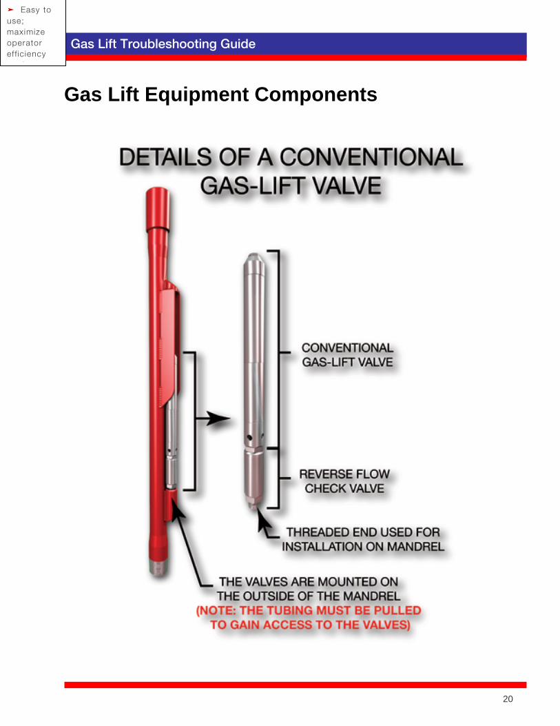
Gas Lift Equipment Components
➤ Easy to use; maximize operator eff iciency
A t
20