PCM-R300 - Taperssection.com - Index · – 1 – SERVICE MANUAL PCM-R300 DIGITAL AUDIO RECORDER US...
58
SERVICE MANUAL PCM-R300 DIGITAL AUDIO RECORDER US Model Canadian Model AEP Model UK Model SPECIFICATIONS Model Name Using Similar Mechanism Tape Transport Mechanism Type DTC-A6 DATM-110A – Continued on next page – Ver 1.1 2001. 06 9-922-708-12 2001F0200-1 © 2001.6 Sony Corporation Home Audio Company Shinagawa Tec Service Manual Production Group
Transcript of PCM-R300 - Taperssection.com - Index · – 1 – SERVICE MANUAL PCM-R300 DIGITAL AUDIO RECORDER US...

– 1 –
SERVICE MANUALPCM-R300
DIGITAL AUDIO RECORDER
US ModelCanadian Model
AEP ModelUK Model
SPECIFICATIONS
Model Name Using Similar Mechanism
Tape Transport Mechanism Type
DTC-A6
DATM-110A
– Continued on next page –
Ver 1.1 2001. 06
9-922-708-122001F0200-1
© 2001.6
Sony CorporationHome Audio Company
Shinagawa Tec Service Manual Production Group

– 2 –
ATTENTION AU COMPOSANT AYANT RAPPORT
À LA SÉCURITÉ!!
LES COMPOSANTS IDENTIFIÉS PAR UNE MARQUE ! SUR
LES DIAGRAMMES SCHÉMATIQUES ET LA LISTE DES
PIÈCES SONT CRITIQUES POUR LA SÉCURITÉ DE
FONCTIONNEMENT. NE REMPLACER CES COMPOSANTS
QUE PAR DES PIÈCES SONY DONT LES NUMÉROS
SONT DONNÉS DANS CE MANUEL OU DANS LES
SUPPLÉMENTS PUBLIÉS PAR SONY.
SAFETY-RELATED COMPONENT WARNING !!
COMPONENTS IDENTIFIED BY MARK ! OR DOTTED LINE
WITH MARK ! ON THE SCHEMATIC DIAGRAMS AND IN
THE PARTS LIST ARE CRITICAL TO SAFE OPERATION.
REPLACE THESE COMPONENTS WITH SONY PARTS
WHOSE PART NUMBERS APPEAR AS SHOWN IN THIS
MANUAL OR IN SUPPLEMENTS PUBLISHED BY SONY.
MODEL IDENTIFICATION
— Back Panel —
Notes on chip component replacement• Never reuse a disconnected chip component.• Notice that the minus side of a tantalum capacitor may be
damaged by heat.
Parts No.
3-018-941-0π : US, Canadian model3-018-941-1π : AEP, UK model
– 3 –
TABLE OF CONTENTS
1. SERVICING NOTE ........................................................... 4
2. GENERAL .......................................................................... 5
3. DISASSEMBLY3-1. Case ..................................................................................... 143-2. Cassette Window ................................................................. 143-3. Mechanism Deck ................................................................ 143-4. Cassette Holder Assembly .................................................. 143-5. Cassette Compartment Motor (M901), Pulley,
Driving Gear and Slider ...................................................... 153-6. Drum Drive Board and Driving Chassis ............................. 153-7. Drum ................................................................................... 163-8. Capstan Motor (M902) ....................................................... 16
4. ADJUSTMENTS ............................................................ 17
5. DIAGRAMS5-1. Circuit Boards Location ..................................................... 215-2. Block Diagrams
• MD Section ...................................................................... 22• Main Section .................................................................... 23• Display/Power Section ..................................................... 25
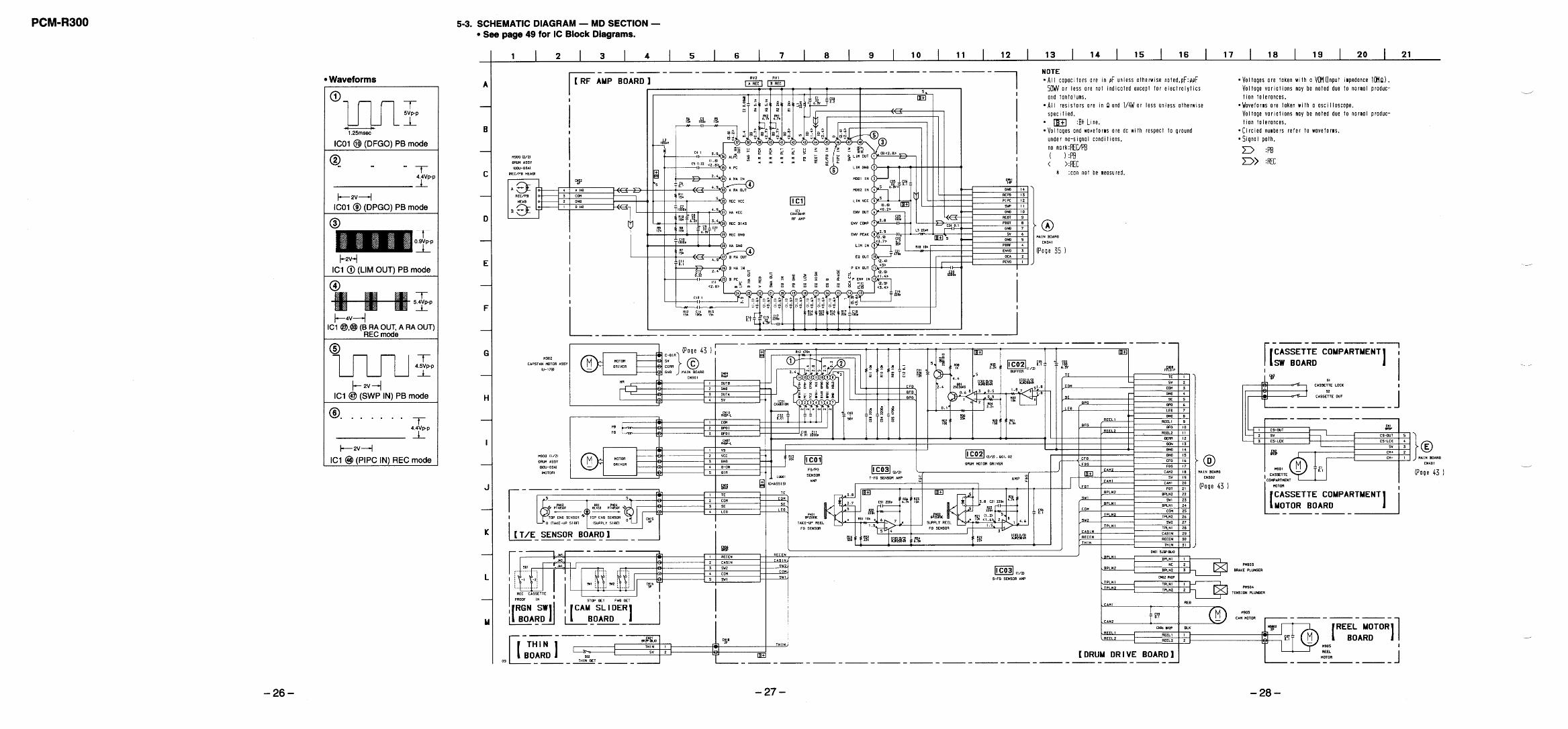
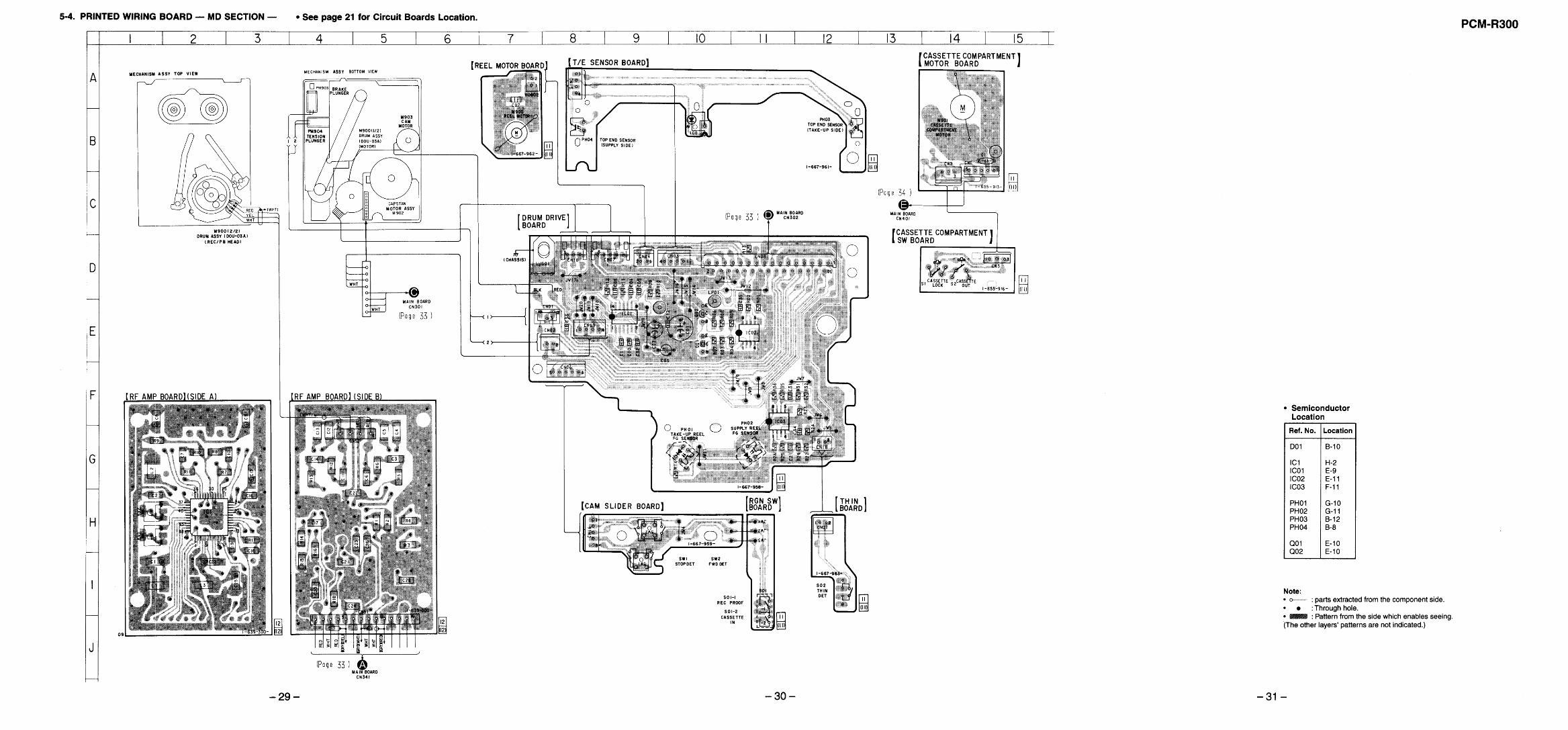
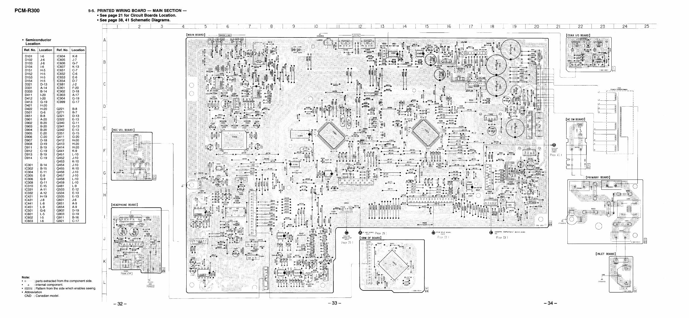
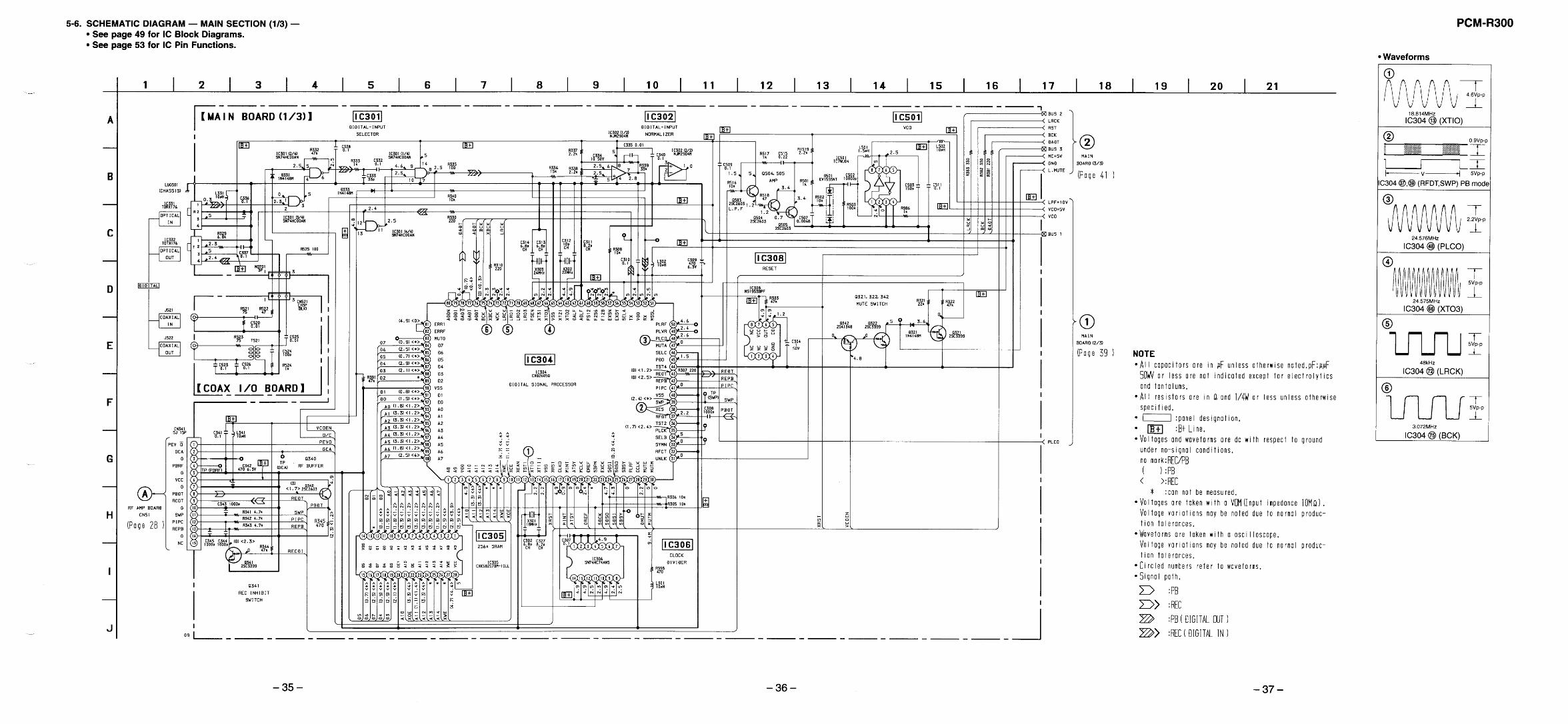
5-3. Schematic Diagram — MD Section —.............................. 265-4. Printed Wiring Board — MD Section — ........................... 295-5. Printed Wiring Board — Main Section — ......................... 325-6. Schematic Diagram — Main Section (1/3) — ................... 355-7. Schematic Diagram — Main Section (2/3) — ................... 385-8. Schematic Diagram — Main Section (3/3) — ................... 415-9. Printed Wiring Board — Dispaly Section — ..................... 445-10. Schematic Diagram — Display Section — ...................... 475-11. IC Block Diagrams ........................................................... 495-12. IC Pin Functions ............................................................... 53
6. EXPLODED VIEWS6-1. Case and Back Panel Section .............................................. 596-2. Front panel Section ............................................................. 606-3. Chassis Section ................................................................... 616-4. Cassette Compartment Section ........................................... 626-5. Chassis L/R Section ............................................................ 636-6. Mechanism Section-1 (DATM-110A) ................................ 646-7. Mechanism Section-2 (DATM-110A) ................................ 656-8. Mechanism Section-3 (DATM-110A) ................................ 66
7. ELECTRICAL PARTS LIST ........................................ 67
SAFETY CHECK-OUT
After correcting the original service problem, perform the followingsafety checks before releasing the set to the customer:Check the antenna terminals, metal trim, “metallized” knobs, screws,and all other exposed metal parts for AC leakage. Check leakage asdescribed below.
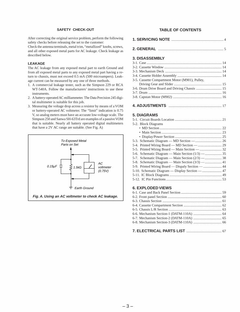
LEAKAGEThe AC leakage from any exposed metal part to earth Ground andfrom all exposed metal parts to any exposed metal part having a re-turn to chassis, must not exceed 0.5 mA (500 microampers). Leak-age current can be measured by any one of three methods.1. A commercial leakage tester, such as the Simpson 229 or RCA
WT-540A. Follow the manufacturers’ instructions to use theseinstruments.
2. A battery-operated AC milliammeter. The Data Precision 245 digi-tal multimeter is suitable for this job.
3. Measuring the voltage drop across a resistor by means of a VOMor battery-operated AC voltmeter. The “limit” indication is 0.75V, so analog meters must have an accurate low-voltage scale. TheSimpson 250 and Sanwa SH-63Trd are examples of a passive VOMthat is suitable. Nearly all battery operated digital multimetersthat have a 2V AC range are suitable. (See Fig. A)
Fig. A. Using an AC voltmeter to check AC leakage.
ACvoltmeter(0.75V)
1.5kΩ0.15µF
Earth Ground
To Exposed MetalParts on Set
– 4 –
SECTION 1SERVICING NOTE
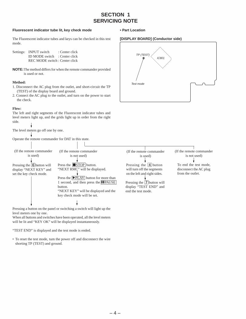
Fluorescent indicator tube lit, key check mode
The Fluorescent indicator tubes and keys can be checked in this testmode.
Settings: INPUT switch : Center clickID MODE switch : Center clickREC MODE switch : Center click
NOTE:The method differs for when the remote commander providedis used or not.
Method:1. Disconnect the AC plug from the outlet, and short-circuit the TP
(TEST) of the display board and ground.2. Connect the AC plug to the outlet, and turn on the power to start
the check.
Flow:The left and right segments of the Fluorescent indicator tubes andlevel meters light up, and the grids light up in order from the rightside.
The level meters go off one by one.
Operate the remote commander for DAT in this state.
Pressing the 6button willdisplay “NEXT KEY” andset the key check mode.
Pressing a button on the panel or switching a switch will light up thelevel meters one by one.When all buttons and switches have been operated, all the level meterswill be lit and “KEY OK” will be displayed instantaneously.
“TEST END” is displayed and the test mode is ended.
• To reset the test mode, turn the power off and disconnect the wireshorting TP (TEST) and ground.
Test mode
IC801TP (TEST)
Pressing the 4 buttonwill turn off the segmentson the left and right sides.
Pressing the 7button willdisplay “TEST END” andend the test mode.
• Part Location
[DISPLAY BOARD] (Conductor side)
(If the remote commanderis not used)
Press the pSTOP button.“NEXT RMC” will be displayed.
Press the ”PLAY button for more than1 second, and then press the PPAUSEbutton.“NEXT KEY” will be displayed and thekey check mode will be set.
(If the remote commanderis used)
(If the remote commanderis used)
(If the remote commanderis not used)
To end the test mode,disconnect the AC plugfrom the outlet.
– 5 –
SECTION 2GENERAL
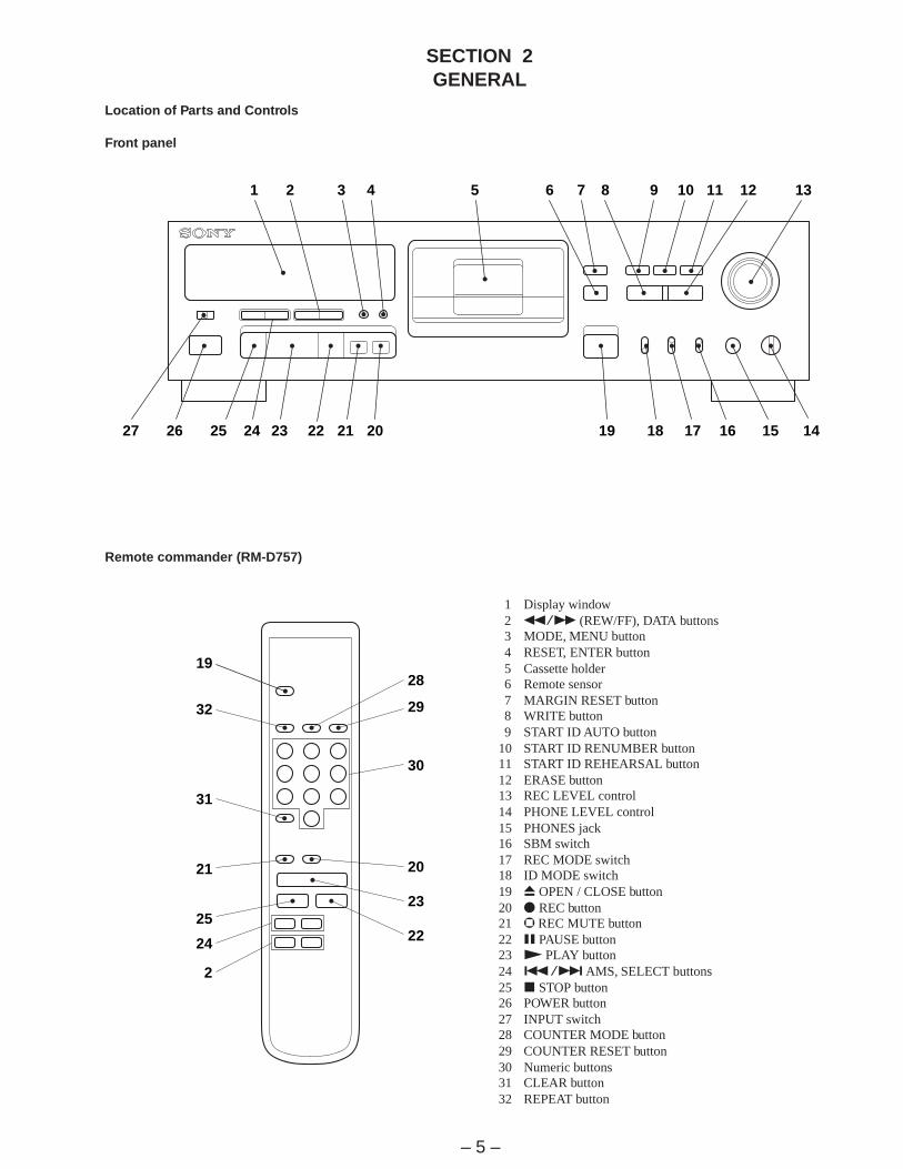
Location of Parts and Controls
Front panel
1 Display window2 0/) (REW/FF), DATA buttons3 MODE, MENU button4 RESET, ENTER button5 Cassette holder6 Remote sensor7 MARGIN RESET button8 WRITE button9 START ID AUTO button
10 START ID RENUMBER button11 START ID REHEARSAL button12 ERASE button13 REC LEVEL control14 PHONE LEVEL control15 PHONES jack16 SBM switch17 REC MODE switch18 ID MODE switch19 6 OPEN / CLOSE button20 r REC button21 R REC MUTE button22 P PAUSE button23 ( PLAY button24 =/+ AMS, SELECT buttons25 p STOP button26 POWER button27 INPUT switch28 COUNTER MODE button29 COUNTER RESET button30 Numeric buttons31 CLEAR button32 REPEAT button
Remote commander (RM-D757)
27 26 25 24 23 22 21 20 19 18 17 16 15 14
13121110987654321
19
32
31
21
25
24
2
22
23
20
30
29
28

– 6 –
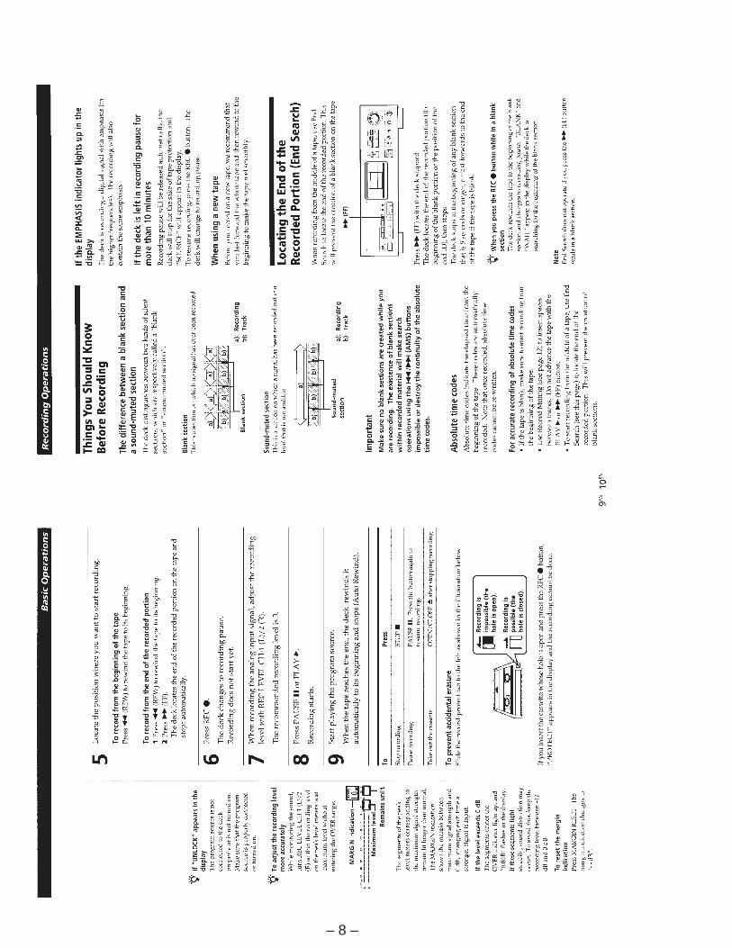
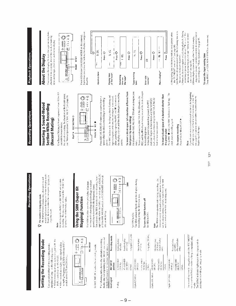
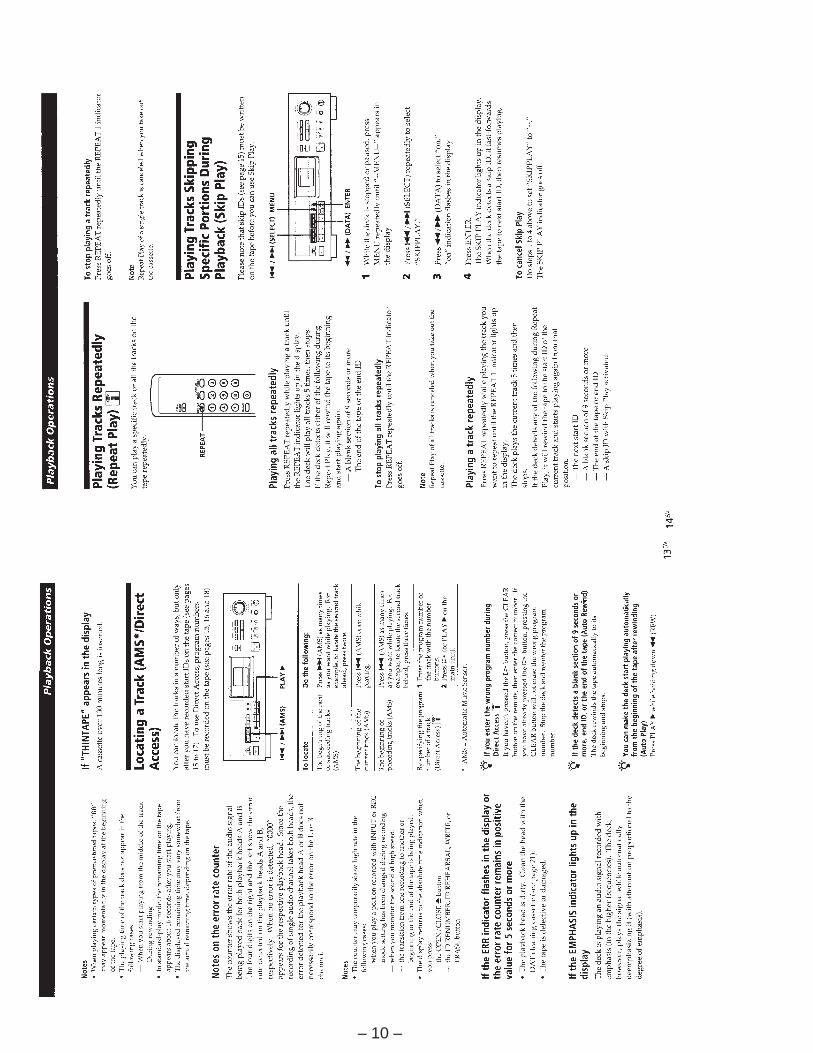
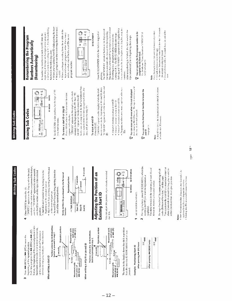
This section is extracted frominstruction manual.
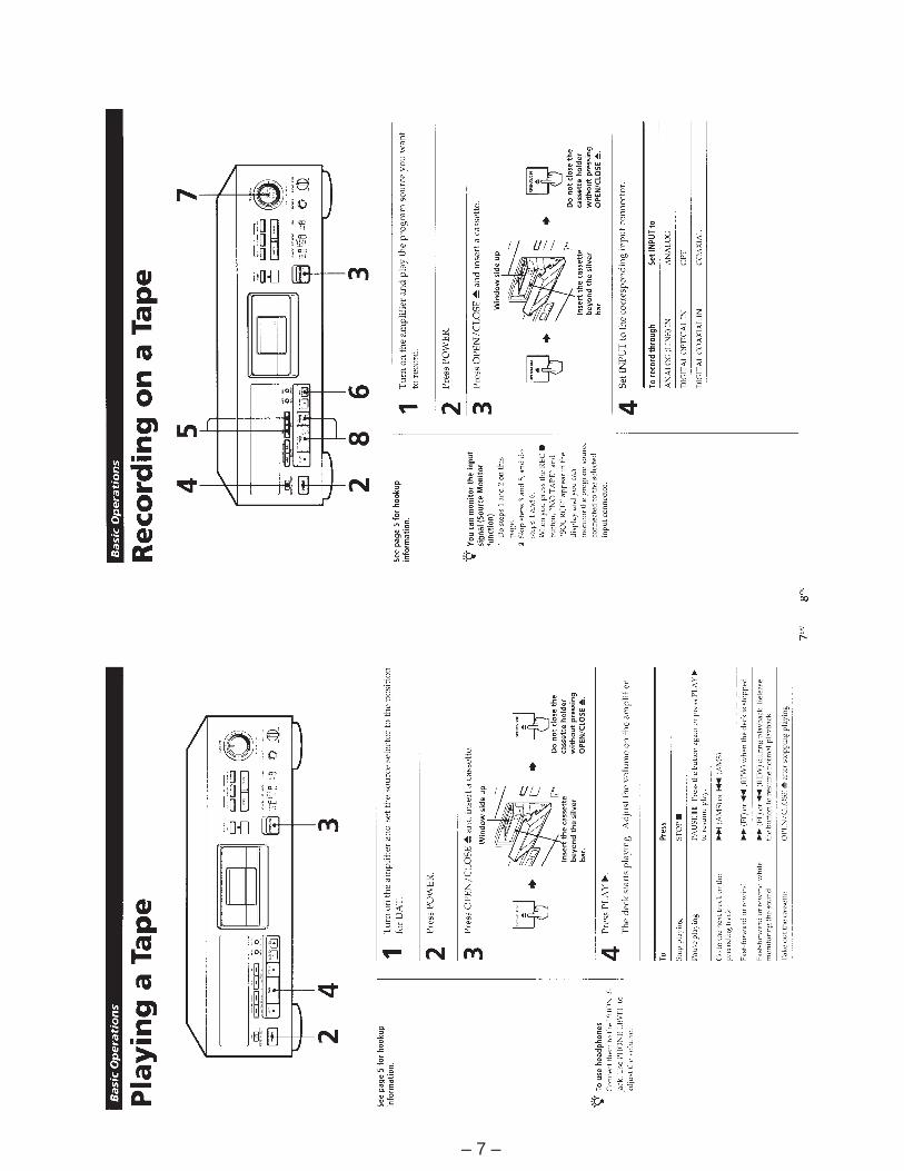
– 7 –
– 8 –
– 9 –
– 10 –

– 11 –
– 12 –
– 13 –
– 14 –
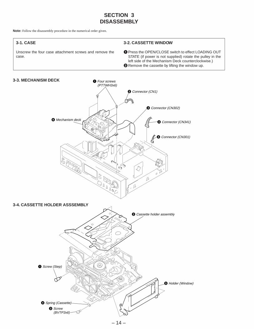
SECTION 3DISASSEMBLY
Note: Follow the disassembly procedure in the numerical order given.
3-3. MECHANISM DECK
3-4. CASSETTE HOLDER ASSSEMBLY
3-1. CASE
Unscrew the four case attachment screws and remove thecase.
3-2. CASSETTE WINDOW
1Press the OPEN/CLOSE switch to effect LOADING OUTSTATE (if power is not supplied) rotate the pulley in theleft side of the Mechanism Deck counterclockwise.)
2Remove the cassette by lifting the window up.
1 Four screws (PTTWH3x6)
2 Connector (CN1)
3 Connector (CN302)
4 Connector (CN341)
5 Connector (CN301)
6 Mechanism deck
2 Cassette holder assembly
5 Holder (Window)
3 Screw (BVTP3x6)
4 Spring (Cassette)
1 Screw (Step)

– 15 –
3-5. CASSETTE COMPARTMENT MOTOR (M901), PULLEY, DRIVING GEAR AND SLIDER
3-6. DRUM DRIVE BOARD AND DRIVING CHASSIS
9 Cassette compartment motor (M901)
8 Two screws (P2.6x3)
6 Two screws (BTP1.7x3)
2 Screw (BTP1.7x3)
4 Screw (BTP1.7x3)
1 Belt (Driving)
3 Pulley
5 Driving gear
7 Slider
2 Two screw (B2.6x4)
4 Drum drive board
1 Screw (BTP2.6x6)
6 Screw (BTP2.6x8)
5 Two screw (BTP2.6x8)
8 Driving chassis
7 Screw (B2.6x4)
3 Remove the lead wiresfrom connectors on thedrum drive board.
– 16 –
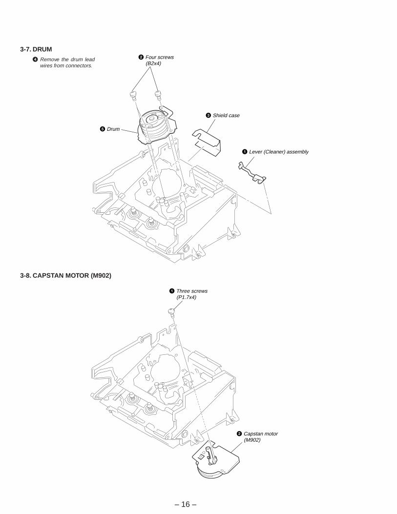
3-7. DRUM
3-8. CAPSTAN MOTOR (M902)
2 Four screws (B2x4)
5 Drum
3 Shield case
1 Lever (Cleaner) assembly
1 Three screws (P1.7x4)
2 Capstan motor (M902)
4 Remove the drum leadwires from connectors.
– 17 –
Hub hole
Hub hole
Slider lock
Slider
Slider lock
Lid
Slider
Cut here.
Tape
Step screw
Spring(cassette)
Screw(BVTP3x6)
Holder
Holder(window)
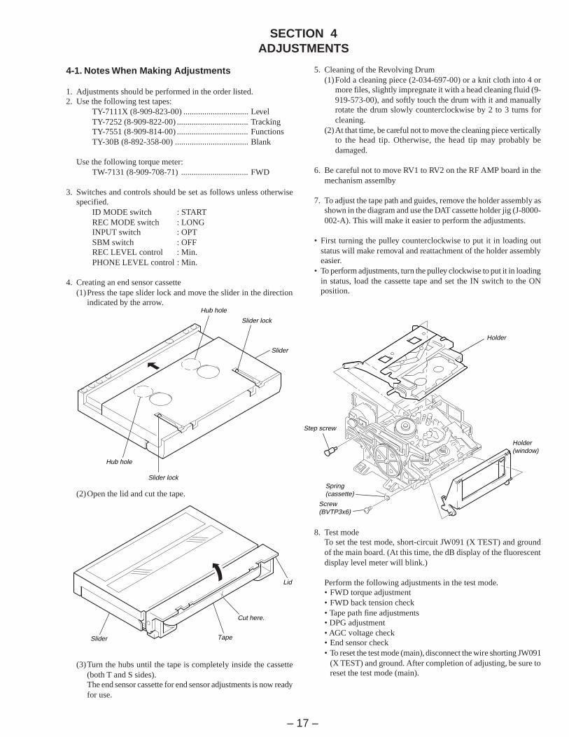
SECTION 4ADJUSTMENTS
4-1. Notes When Making Adjustments
1. Adjustments should be performed in the order listed.2. Use the following test tapes:
TY-7111X (8-909-823-00) ............................... LevelTY-7252 (8-909-822-00) .................................. TrackingTY-7551 (8-909-814-00) .................................. FunctionsTY-30B (8-892-358-00) ................................... Blank
Use the following torque meter:TW-7131 (8-909-708-71) ................................ FWD
3. Switches and controls should be set as follows unless otherwisespecified.
ID MODE switch : STARTREC MODE switch : LONGINPUT switch : OPTSBM switch : OFFREC LEVEL control : Min.PHONE LEVEL control : Min.
4. Creating an end sensor cassette(1)Press the tape slider lock and move the slider in the direction
indicated by the arrow.
(2)Open the lid and cut the tape.
(3)Turn the hubs until the tape is completely inside the cassette(both T and S sides).The end sensor cassette for end sensor adjustments is now readyfor use.
5. Cleaning of the Revolving Drum(1)Fold a cleaning piece (2-034-697-00) or a knit cloth into 4 or
more files, slightly impregnate it with a head cleaning fluid (9-919-573-00), and softly touch the drum with it and manuallyrotate the drum slowly counterclockwise by 2 to 3 turns forcleaning.
(2)At that time, be careful not to move the cleaning piece verticallyto the head tip. Otherwise, the head tip may probably bedamaged.
6. Be careful not to move RV1 to RV2 on the RF AMP board in themechanism assemlby
7. To adjust the tape path and guides, remove the holder assembly asshown in the diagram and use the DAT cassette holder jig (J-8000-002-A). This will make it easier to perform the adjustments.
• First turning the pulley counterclockwise to put it in loading outstatus will make removal and reattachment of the holder assemblyeasier.
• To perform adjustments, turn the pulley clockwise to put it in loadingin status, load the cassette tape and set the IN switch to the ONposition.
8. Test modeTo set the test mode, short-circuit JW091 (X TEST) and groundof the main board. (At this time, the dB display of the fluorescentdisplay level meter will blink.)
Perform the following adjustments in the test mode.• FWD torque adjustment• FWD back tension check• Tape path fine adjustments• DPG adjustment• AGC voltage check• End sensor check• To reset the test mode (main), disconnect the wire shorting JW091
(X TEST) and ground. After completion of adjusting, be sure toreset the test mode (main).
– 18 –
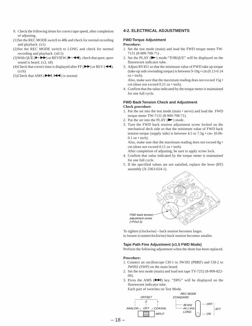
4-2. ELECTRICAL ADJUSTMENTS
FWD Torque AdjustmentProcedure:1. Set the test mode (main) and load the FWD torque meter TW-
7131 (8-909-708-71) .2. Set the PLAY (() mode.“TORQUE” will be displayed on the
fluorescent indicator tube.3. Adjust RV451 so that the minimum value of FWD take up torque
(take-up side rewinding torque) is between 9-10g • cm (0.13-0.14oz • inch).Also, make sure that the maximum reading does not exceed 15g •cm (does not exceed 0.21 oz • inch).
4. Confirm that the value indicated by the torque meter is maintainedfor one full cycle.
FWD Back Tension Check and AdjustmentCheck procedure:1. Put the set into the test mode (main • servo) and load the FWD
torque meter TW-7131 (8-909-708-71).2. Put the set into the PLAY (() mode.3. Turn the FWD back tension adjustment screw locked on the
mechanical deck side so that the minimum value of FWD backtension torque (supply side) is between 4.5 to 7.5g • cm- (0.06-0.1 oz • inch).Also, make sure that the maximum reading does not exceed 8g •cm (does not exceed 0.11 oz • inch).After completion of adjusting, be sure to apply screw lock.
4. Confirm that value indicated by the torque meter is maintainedfor one full cycle.
5. If the specified values are not satisfied, replace the lever (BT)assembly (X-3363-024-1).
To tighten (clockwise) - back tension becomes larger.to loosen (counterclockwise)-back tension becomes smaller.
Tape Path Fine Adjustment (x1.5 FWD Mode)Perform the following adjustment when the drum has been replaced.
Procedure:1. Connect an oscilloscope CH-1 to JW183 (PBRF) and CH-2 to
JW092 (SWP) on the main board.2. Set the test mode (main) and load test tape TY-7252 (8-909-822-
00).3. Press the AMS (+) key. “DPG” will be displayed on the
fluorescent indicator tube.Each part of switches on Test Mode.
FWD back tensionadjustment screw(+P2x2.5)
OPT COAXIAL
INPUT
ANALOG
OFFSET
48 kHz44.1 kHzLONG
STANDARDREC MODE
OFF
ON
AFT
– 0 +
9. Check the following items for correct tape speed, after completionof adjusting.
(1)Set the REC MODE switch to 48k and check for normal recordingand playback. (x1)
(2)Set the REC MODE switch to LONG and check for normalrecording and playback. (x0.5)
(3)With QUE (”+)) or REVIEW (”+0), check that qurrr, qurrrsound is heard. (x3, x8)
(4)Check that correct time is displayed after FF ()) or REV (0).(x16)
(5)Check that AMS (+, =) is normal.
– 19 – – 20 –
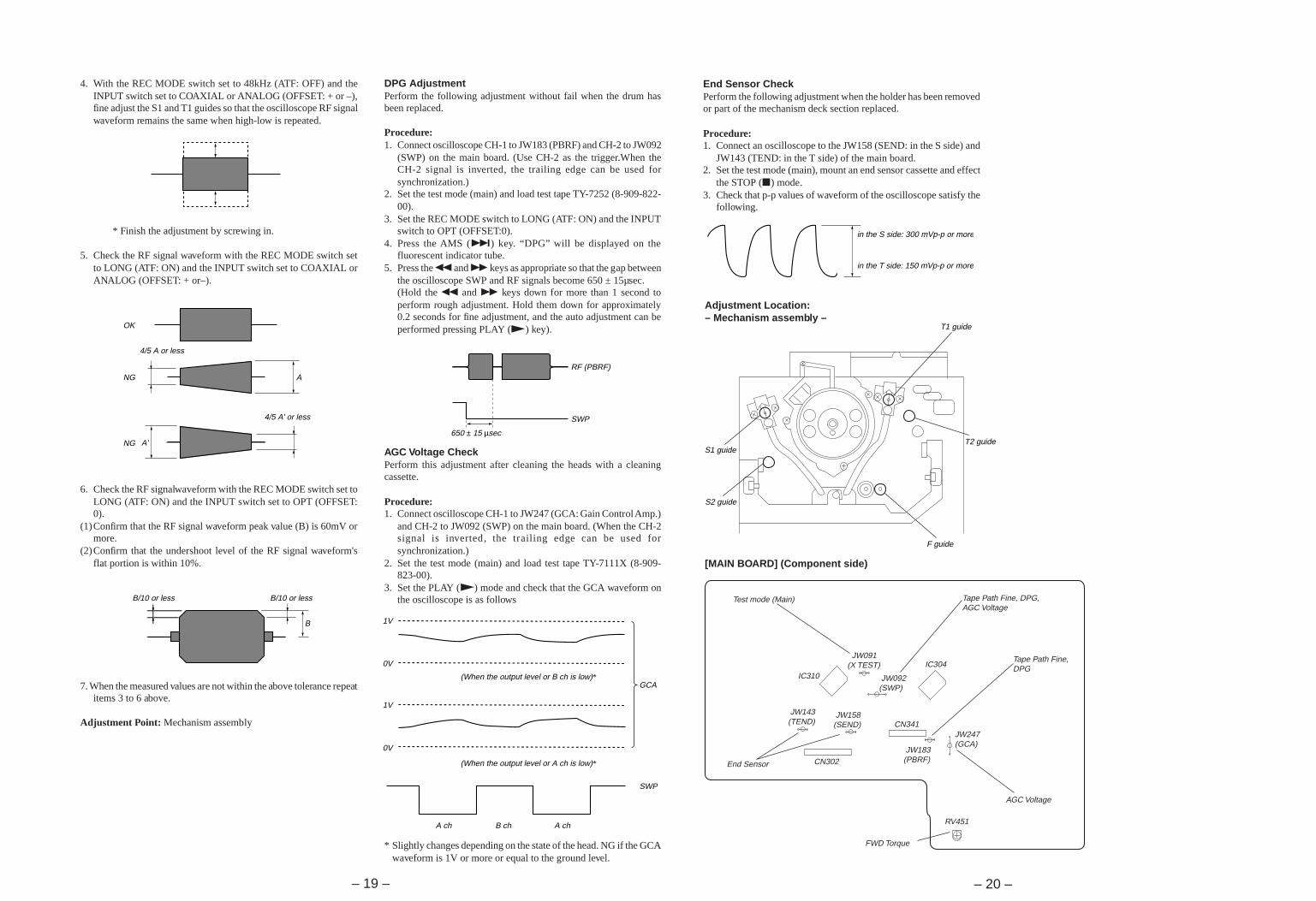
DPG AdjustmentPerform the following adjustment without fail when the drum hasbeen replaced.
Procedure:1. Connect oscilloscope CH-1 to JW183 (PBRF) and CH-2 to JW092
(SWP) on the main board. (Use CH-2 as the trigger.When theCH-2 signal is inverted, the trailing edge can be used forsynchronization.)
2. Set the test mode (main) and load test tape TY-7252 (8-909-822-00).
3. Set the REC MODE switch to LONG (ATF: ON) and the INPUTswitch to OPT (OFFSET:0).
4. Press the AMS (+) key. “DPG” will be displayed on thefluorescent indicator tube.
5. Press the 0 and ) keys as appropriate so that the gap betweenthe oscilloscope SWP and RF signals become 650 ± 15µsec.(Hold the 0 and ) keys down for more than 1 second toperform rough adjustment. Hold them down for approximately0.2 seconds for fine adjustment, and the auto adjustment can beperformed pressing PLAY (() key).
AGC Voltage CheckPerform this adjustment after cleaning the heads with a cleaningcassette.
Procedure:1. Connect oscilloscope CH-1 to JW247 (GCA: Gain Control Amp.)
and CH-2 to JW092 (SWP) on the main board. (When the CH-2signal is inverted, the trailing edge can be used forsynchronization.)
2. Set the test mode (main) and load test tape TY-7111X (8-909-823-00).
3. Set the PLAY (() mode and check that the GCA waveform onthe oscilloscope is as follows
* Slightly changes depending on the state of the head. NG if the GCAwaveform is 1V or more or equal to the ground level.
End Sensor CheckPerform the following adjustment when the holder has been removedor part of the mechanism deck section replaced.
Procedure:1. Connect an oscilloscope to the JW158 (SEND: in the S side) and
JW143 (TEND: in the T side) of the main board.2. Set the test mode (main), mount an end sensor cassette and effect
the STOP (p) mode.3. Check that p-p values of waveform of the oscilloscope satisfy the
following.
Adjustment Location:– Mechanism assembly –
[MAIN BOARD] (Component side)
RF (PBRF)
SWP
650 ± 15 µsec
1V
0V
0V
1V
(When the output level or B ch is low)*
(When the output level or A ch is low)*
GCA
SWP
A chA ch B ch
in the S side: 300 mVp-p or more
in the T side: 150 mVp-p or more
T1 guide
T2 guide
F guide
S1 guide
S2 guide
IC310IC304
CN341
CN302End Sensor
Test mode (Main) Tape Path Fine, DPG,AGC Voltage
Tape Path Fine,DPG
AGC Voltage
FWD Torque
JW091(X TEST)
JW092(SWP)
JW143(TEND)
JW158(SEND)
JW183(PBRF)
JW247(GCA)
RV451
4. With the REC MODE switch set to 48kHz (ATF: OFF) and theINPUT switch set to COAXIAL or ANALOG (OFFSET: + or –),fine adjust the S1 and T1 guides so that the oscilloscope RF signalwaveform remains the same when high-low is repeated.
* Finish the adjustment by screwing in.
5. Check the RF signal waveform with the REC MODE switch setto LONG (ATF: ON) and the INPUT switch set to COAXIAL orANALOG (OFFSET: + or–).
6. Check the RF signalwaveform with the REC MODE switch set toLONG (ATF: ON) and the INPUT switch set to OPT (OFFSET:0).
(1)Confirm that the RF signal waveform peak value (B) is 60mV ormore.
(2)Confirm that the undershoot level of the RF signal waveform'sflat portion is within 10%.
7. When the measured values are not within the above tolerance repeatitems 3 to 6 above.
Adjustment Point: Mechanism assembly
OK
NG A
A'NG
4/5 A or less
4/5 A' or less
B
B/10 or lessB/10 or less
– 21 –– 22 –
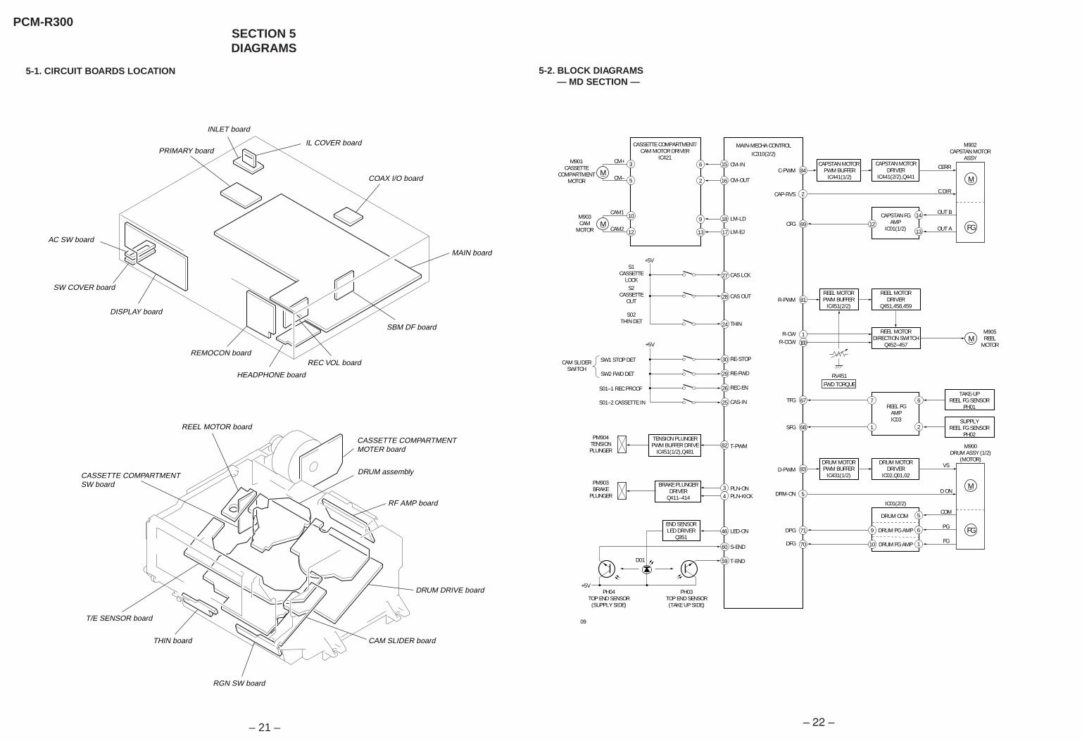
5-1. CIRCUIT BOARDS LOCATION
SECTION 5DIAGRAMS
5-2. BLOCK DIAGRAMS — MD SECTION —
PCM-R300
INLET board
PRIMARY board
AC SW board
IL COVER board
COAX I/O board
MAIN board
SW COVER board
DISPLAY board
REMOCON board
HEADPHONE board
REEL MOTOR board
REC VOL board
SBM DF board
CASSETTE COMPARTMENT SW board
CASSETTE COMPARTMENT MOTER board
DRUM assembly
RF AMP board
DRUM DRIVE board
CAM SLIDER board
RGN SW board
THIN board
T/E SENSOR board
2
2
3
5
6
9
16
17
10
12 13
8415
13
CERR
C DIR
OUT B
OUT A12
14
1100
M
CM+
CM–
M
M
FG
CAM1
CAM2
1869M
1
67
68
7
2
6
CM-INC-PWM
CAP-RVS
CFG
R-CWR-CCW
TFG
SFG
DRM-ON
DPG
DFG
CM-OUT
LM-LD
LM-EJ
30 RE-STOP
27 CAS LCK
CAPSTAN MOTOR PWM BUFFER
IC441(1/2)
CAPSTAN FGAMP
IC01(1/2)
REEL FGAMPIC03
CAPSTAN MOTORDRIVER
IC441(2/2),Q441
CASSETTE COMPARTMENT/CAM MOTOR DRIVER
IC421M901
CASSETTECOMPARTMENT
MOTOR
81R-PWMREEL MOTORPWM BUFFER
IC451(2/2)
REEL MOTORDRIVER
Q451,458,459
3BRAKE PLUNGERDRIVER
Q411–414 4
REEL MOTORDIRECTION SWITCH
Q452–457
TAKE-UPREEL FG SENSOR
PH01
SUPPLYREEL FG SENSOR
PH02
5
83
1
VS
D ON
DRUM COM
DRUM PG AMP
DRUM FG AMP
IC01(2/2)COM
FG
9
5
M
FG71
D-PWMDRUM MOTORPWM BUFFER
IC431(1/2)
M902CAPSTAN MOTOR
ASSY
M905REEL
MOTOR
M903CAM
MOTOR
M900DRUM ASSY (1/2)
(MOTOR)DRUM MOTORDRIVER
IC02,Q01,02
1070
46
60
59
PG6
END SENSORLED DRIVER
Q351
TENSION PLUNGERPWM BUFFER DRIVE
IC451(1/2),Q48182
29 RE-FWD
26 REC-EN
25 CAS-IN
T-PWM
PLN-ONPLN-KICK
LED-ON
S-END
T-END
28 CAS OUT
SW1 STOP DET
SW2 FWD DET
S01–1 REC PROOF
S01–2 CASSETTE IN
S1CASSETTE
LOCK
CAM SLIDERSWITCH
PM904TENSIONPLUNGER
PM903BRAKE
PLUNGER
PH04TOP END SENSOR
(SUPPLY SIDE)
PH03TOP END SENSOR(TAKE UP SIDE)
S2CASSETTE
OUT
24 THIN
S02THIN DET
+5V
+5V
+5V
D01
RV451FWD TORQUE
MAIN-MECHA CONTROLIC310(2/2)
09
– 22 –

– 51 –
12
3
4
5
6
7
8
OVER CURRENTPROTECTION
CIRCUIT
OVER CURRENTPROTECTION
CIRCUIT
OVER HEATPROTECTION
CIRCUITSTART
CIRCUIT
REFERENCEVOLTAGECIRCUIT
ERRORAMP
ERRORAMP
GNDBALANCE ADJ
OUT(–)
IN(–)
VOLTAGE ADJ
OUT(+)
IN(+)
OUT CONTROL
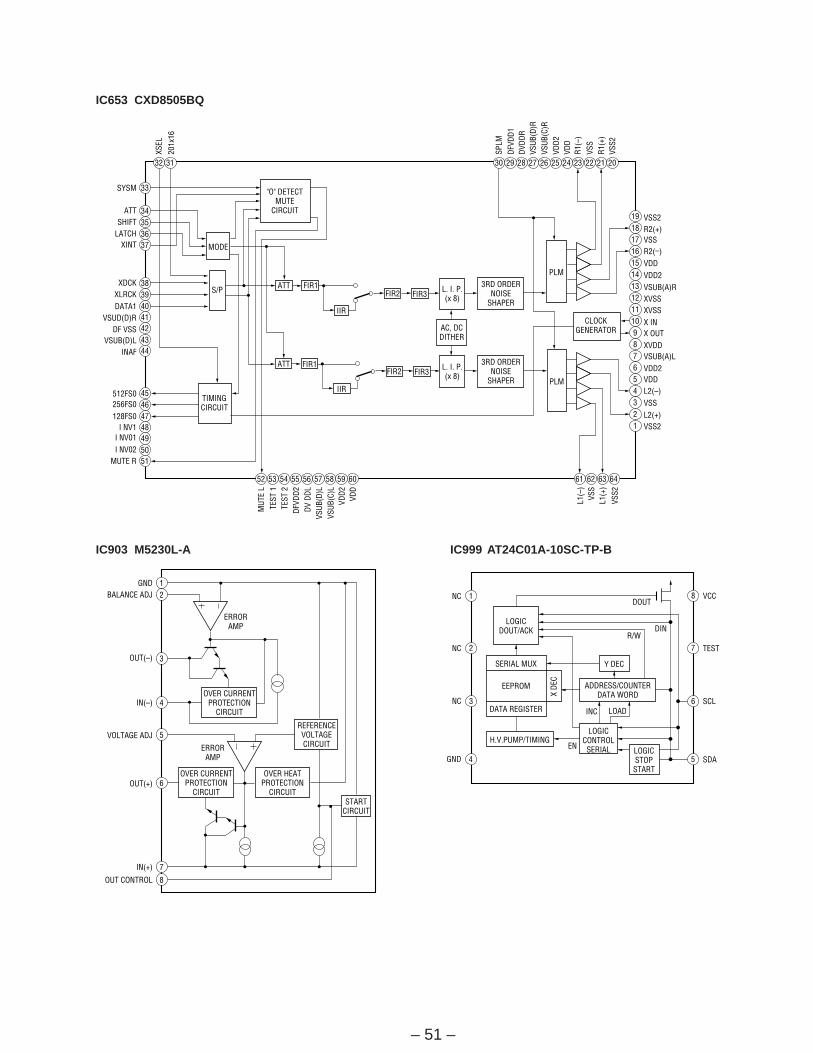
IC903 M5230L-A
1
2
3
4 5
6
7
8
LOGICDOUT/ACK
X DE
C
DATA REGISTER
SERIAL MUX
EEPROM ADDRESS/COUNTERDATA WORD
LOGICCONTROLSERIAL LOGIC
STOPSTART
H.V.PUMP/TIMING
Y DEC
DOUT
R/WDIN
INC LOAD
EN
VCC
TEST
SCL
SDA
NC
NC
NC
GND
IC999 AT24C01A-10SC-TP-B
32 31 30 29 28 27 26 25 24 23 22 21 20
19181716151413121110987654321
34
33
353637
38394041424344
45464748495051
52 53 54 55 56 57 58 59 60 61 62 63 64
PLM
PLM
CLOCKGENERATOR
TIMINGCIRCUIT
S/P
MODE
"O" DETECTMUTE
CIRCUIT
ATT FIR1FIR2 FIR3
L. I. P.(x 8)
IIR
ATT FIR1
IIR
3RD ORDERNOISE
SHAPER
FIR2 FIR3L. I. P.(x 8)
3RD ORDERNOISE
SHAPER
AC, DCDITHER
SYSM
ATTSHIFT
LATCHXINT
XDCKXLRCKDATA1
VSUD(D)RDF VSS
VSUB(D)LINAF
512FS0256FS0128FS0
I NV1I NV01I NV02
MUTE R
VSS2R2(+)VSSR2(–)VDDVDD2VSUB(A)RXVSSXVSSX INX OUTXVDDVSUB(A)LVDD2VDDL2(–)
L2(+)VSS
VSS2
XSEL
SPLM
DFVD
D1DV
DDR
VSUB
(D)R
VSUB
(C)R
VDD2
VDD
R1(–
)VS
SR1
(+)
VSS2
201x
16
MUT
E L
TEST
1TE
ST 2
DFVD
D2DV
DDL
VSUB
(D)L
VSUB
(C)L
VDD2
VDD
L1(–
)
L1(+
)VS
S
VSS2
IC653 CXD8505BQ
– 52 –
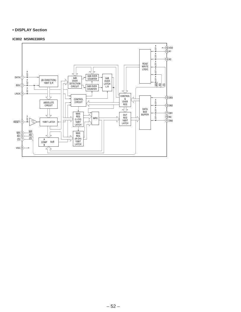
• DISPLAY Section
IC802 MSM6338RS
8
765
4
3
1615
13
12
11
9
14
2
1
10
15BIT LATCH
0dB OVERCOUNTER
0dB OVERCOUNTER
0dBOVERLATCH
L.R
0dBOVER
DETECTIONCIRCUIT
ACOMP
BA≥B
ABSOLUTECIRCUIT
(BI-DIRECTION)16BIT S.R
CONTROLCIRCUIT
MAXREG
(L-CH)15BITLATCH
MAXREG
(R-CH)15BITLATCH
CONTROL&
OVERREG
OUTREG
16BITLATCH
DATABUS
BUFFER
READWRITELOGIC
MPX
WR WR
CSCS
RD
WR
CSRD
RD
VSS
DATA
BCK
LRCK
RESET DB0
NC
DB1
DB2
DB3
A2
A1VDD
– 53 –
Pin No
1, 2
3
4 to 8
9
10
11
12
13
14
15
16
17
18
19
20
21
22
23
24
25
26
27
28
29
30
31
32
33
34
35
36
37
38
39
40
41
42
43
44
45
Pin Name
A8, A9
VDD
A10 to A14
XWE
XCE
XEAN
TST1
XT1O
XT1I
VSS
XRST
CLKO
MINT
ATSY
MCLK
DREF
SBPM
EXCK
SDSI
SDSO
SBSY
PLRF
CCLK
MUTE
MUTM
UNLK
RFCT
SYMN
SELB
PLCK
TST2
RFDT
XCS
SWP
VSS
PIPC
REPB
REDT
TST4
PDO
I/O
O
—
O
O
O
O
I
O
I
—
I
O
O
I
O
O
O
I
I
O
O
O
O
I
O
O
I
O
I
O
I
I
I
I
—
O
O
O
I
O
Function
External RAM address output
Power supply (+5V)
External RAM address output
External RAM write enable signal output
External RAM output enable signal output
Not used
Test pin (Fixed at “L”)
Crystal oscillation circuit 1 output (18 MHz)
Crystal oscillation circuit 1 input (18 MHz)
Ground
Reset input “L”: Reset
Not used
Control byte (1) bit 1=“L”: Q code decode (Detecting between songs) output, “H”: BCK
clock output by RX-PLL
ATF sync signal input
Not used
SBSY period, duty 50 signal output
Not used
Data transfer clock input from main, mecha control
Serial data input from main, mecha control
Serial data output to main, mecha control
Frame sync signal output for transferring data to main, mecha control
Not used
Not used
Mute input “H”: Mute Not mute REC monitor sound
Mute monitor “H”: Indicates muting occurs
RX-PLL lock monitor signal output “L”: Indicates locking occurs
Playback RF signal control (“L”: Valid, “H”: Invalid) (Fixed at “L”)
Outputs monitor signal for C1 check results corresponding to RF
Test pin (Fixed at “H”)
Not used
Test pin (Fixed at “L”)
Playback RF signal input
Chip select input for data transfer with microprocessor “L”: Transfer enable (Fixed at “L”)
RF switching pulse “L”: A track, “H”: B track
Ground
ATF pilot signal/discrimination signal output for record signal “H”: Pilot signal
REC/PB discrimination signal output “H”: REC
Record signal output
Test pin (Fixed at “L”)
RX-PLL phase comparator output
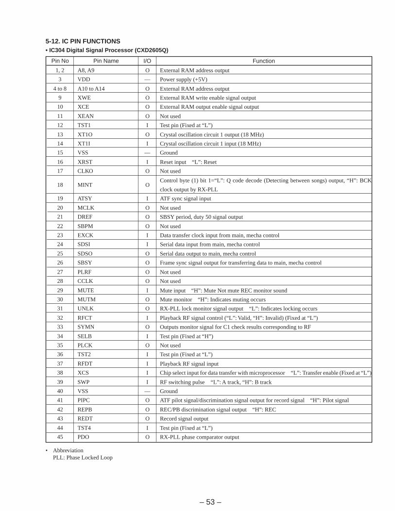
5-12. IC PIN FUNCTIONS• IC304 Digital Signal Processor (CXD2605Q)
• AbbreviationPLL: Phase Locked Loop
– 54 –
Pin No
46
47
48
49
50
51
52
53
54
55
56
57
58
59
60
61
62
63
64
65
66
67
68
69
70
71
72
73
74
75
76
77
78
79
80
81
82
83
84
85 to 89
90
91
92
93 to 100
Pin Name
SELC
MUTA
PLCO
PLVR
PLRF
MSSL
RX
VDD
TX
SELA
EXSY
EXSN
F128
F256
F512
ADLF
DALF
XT2O
XT2I
VSS
XT3O
XT3I
FSEN
LR03
LR02
LR01
LRCK
WCK
XBCK
BCK
ADDT
DADT
DADO
ADDI
ADDN
ERRI
ERRF
MUTG
D7
D6 to D2
VSS
D1
D0
A0 to A7
I/O
I
I
I
O
O
I
I
—
O
I
I/O
I/O
I/O
O
O
I
I
O
I
—
O
I
I
O
O
O
I/O
O
O
I/O
I
O
I
O
I
I
O
O
I/O
I/O
—
I/O
I/O
O
Function
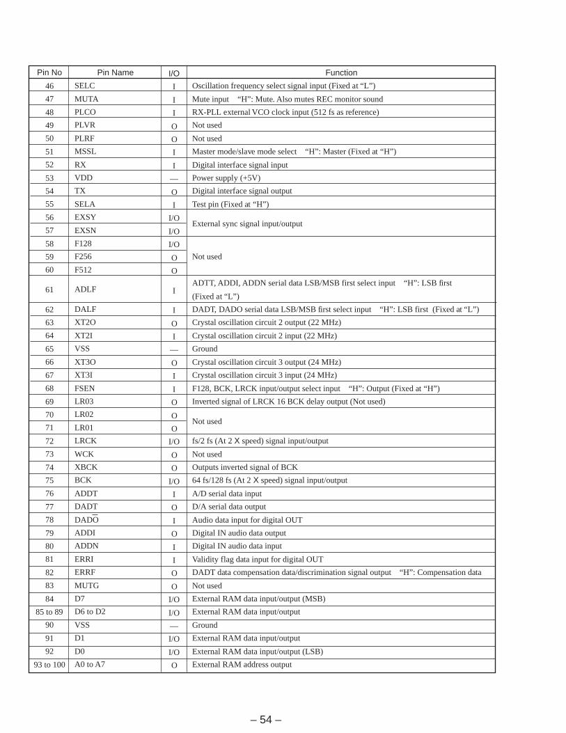
Oscillation frequency select signal input (Fixed at “L”)
Mute input “H”: Mute. Also mutes REC monitor sound
RX-PLL external VCO clock input (512 fs as reference)
Not used
Not used
Master mode/slave mode select “H”: Master (Fixed at “H”)
Digital interface signal input
Power supply (+5V)
Digital interface signal output
Test pin (Fixed at “H”)
External sync signal input/output
Not used
ADTT, ADDI, ADDN serial data LSB/MSB first select input “H”: LSB first
(Fixed at “L”)
DADT, DADO serial data LSB/MSB first select input “H”: LSB first (Fixed at “L”)
Crystal oscillation circuit 2 output (22 MHz)
Crystal oscillation circuit 2 input (22 MHz)
Ground
Crystal oscillation circuit 3 output (24 MHz)
Crystal oscillation circuit 3 input (24 MHz)
F128, BCK, LRCK input/output select input “H”: Output (Fixed at “H”)
Inverted signal of LRCK 16 BCK delay output (Not used)
Not used
fs/2 fs (At 2 X speed) signal input/output
Not used
Outputs inverted signal of BCK
64 fs/128 fs (At 2 X speed) signal input/output
A/D serial data input
D/A serial data output
Audio data input for digital OUT
Digital IN audio data output
Digital IN audio data input
Validity flag data input for digital OUT
DADT data compensation data/discrimination signal output “H”: Compensation data
Not used
External RAM data input/output (MSB)
External RAM data input/output
Ground
External RAM data input/output
External RAM data input/output (LSB)
External RAM address output
– 55 –
Pin No
1
2
3
4
5
6
7
8
9
10
11
12
13
14
15
16
17
18
19
20
21
22
23
24
25
26
27
28
29
30
31
32
33
34
35 to 38
39
40
Pin Name
R-CW
CAP-RVS
PLN-ON
PLN-KICK
DRM-ON
—
DF-DT
DF-CLK
VCOEN
OPT/COA
ADLD
DALD
—
—
CM-IN
CM-OUT
LM-EJ
LM-LD
ROM-DT
—
—
—
H-FIX
THIN
CAS-IN
REC-EN
CAS LCK
CAS OUT
RE-FWD
RE-STOP
—
—
SBM
—
AF3 to AF0
MP
X RST
I/O
O
O
O
O
O
O
O
O
O
O
O
O
—
—
O
O
O
O
O
—
—
—
I
I
I
I
I
I
I
I
—
O
O
O
I
—
I
Function
Reel motor CW output “H”: FWD direction
Capstan direction control output “L”: FWD, “H”: RVS
Brake plunger ON control output
Brake plunger kick control output
Drum motor ON control output
Not used
Communication line (Serial data) with Digital filter
Communication line (Shift clock) with Digital filter “L”: shifted, “H”: taken
VCO enable output “H”: Active
Digital input switch output “H”: coaxial, “L”: optical
Load to Digital filter for A/D converter
Load to Digital filter for D/A converter
Not used
Cassette compartment motor rotation IN direction control output
Cassette compartment motor rotation OUT direction control output
Loading motor rotation Eject direction control output
Loading motor rotation Loading direction control output
Data output to EEP ROM
Not used
Not used (Fixed at “H”)
Detect kinds of tapes “H”: normal tape, “L”: Thin tape
Cassette IN switch input
REC enable switch input
Cassette compartment lock switch input
Cassette compartment out switch input
Encoder SW2 input
Encoder SW1 input
Not used (Open)
Not used
Super bit maping control output “H”: SBM ON, “L”: SBM OFF
Not used
AF mode select
Not used (Connected to Ground)
System reset input “L”: Active
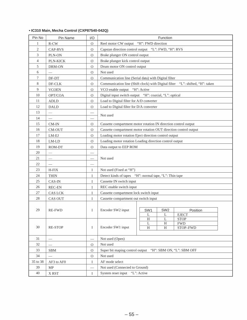
• IC310 Main, Mecha Control (CXP87540-042Q)
SW1LHLH
SW2LLHH
PositionEJECTSTOPFWDSTOP–FWD
– 56 –
Pin No
41
42
43
44
45
46
47
48
49
50
51
52
53
54
55
56
57
58
59
60
61
62
63
64
65
66
67
68
69
70
71
72
73
74
75
76
77
78
79
80
Pin Name
VSS
XTAL
EXTAL
DISP-REQ
REC-DIS
LED-ON
ROM-CK
DSP-ACK
DSP-DI
DSP-DO
DSP-CK
SBSY
SDDI
SDDO
SDCK
AVSS
AVREF
AVDD
T-END
S-END
L-FIX
H-FIX
L-FIX
MUTM
MINT
ATF-IN
TFG
SFG
CFG
DFG
DPG
DREF
ATSY-IN
R-X5/6V
MAIN-CHK
CAS-TST
MCLK
PBDT
SWP
A-PWM
I/O
—
O
I
O
O
O
O
I
I
O
O
I
I
O
O
—
—
—
I
I
I
I
I
I
I
I
I
I
I
I
I
I
I
I
O
I
I
I
O
O
Function
Ground
System clock output (Open)
System clock input (9.408MHz)
Communication request output to display control “L”: Active
Record current control output “H”: Record disable, “L”: Record enable
End sensor ON control output “L”: Active
Clock output to EEPROM
Communication acknowledge input from display control “L”: Active
Serial data input from display control and EEPROM
Serial data output to display control and EEPROM
Serial clock output to display control and EEPROM
SUB SYNC input from CXD2605Q (master)
Serial data input from CXD2605Q
Serial data output to CXD2605Q
Serial clock output to CXD2605Q (for sub code interface)
Ground for A/D port
Reference voltage for A/D port (+5V)
Power supply for A/D port (+5V)
T side end sensor input
S side end sensor input
Fixed at “L”
Fixed at “H”
Fixed at “L”
Mute monitor input “H”: Active
Q code decode value input “H”: Between songs
ATF pilot signal input (Analog input)
T side reel FG signal input
S side reel FG signal input
Capstan FG signal input
Drum FG signal input
Drum PG signal input
Drum reference signal input
DPG auto adjustment FRC signal input
Fixed at “H”
Not used
Test pin “L”: Test mode with no cassette compartment
Channel clock input (9.408MHz)
ATF SYNC PB data input
Switching pulse output
PWM signal output for AGC
– 57 –
Pin No
81
82
83
84
85
86
87
88
89
90
91
92
93
94
95
96
97
98
99
100
Pin Name
R-PWM
T-PWM
D-PWM
C-PWM
L-FIX
XTEST
POW-DWN
VSS
VDD
VPP
ATSY
AREA
ADINT
DAINT
LIN-MUT
—
RLY-MUT
DIG-MUT
—
R-CCW
I/O
O
O
O
O
I
I
I
—
—
—
O
O
O
O
O
—
O
O
—
O
Function
PWM signal output for reel motor
PWM signal output for tension regulater plunger
PWM signal output for drum motor drive
PWM signal output for capstan motor
Fixed at “L”
Test pin “L”: Test mode (For adjustment)
Not used (Fixed at “H”)
Ground
Power supply (+5V)
Connected to +5V
ATF sampling pulse #2 output
Not used
A/D converter reset output “L”: Reset
D/A digital filter reset output “L”: Reset
Line mute output “L”: Active
Not used
Relay mute signal output “L”: Active
Mute signal to CXD2605Q “H”: Active
Not used
Reel motor CCW output “L”: RVS direction
– 58 –
Pin No
1
2
3
4
5
6
7
8
9
10
11
12
13
14 to 21
22 to 29
30
31
32
33
34 to 57
58 to 70
71
72
73
74 to 77
78
79
80
Pin Name
H
RMC
TEST
A1 METER
A2 METER
M MUT
ACK
SC
SI
SO
CS METER
RD METER
WR METER
—
AD0 to AD7
XRST
EXTAL
XTAL
VSS
S0 to S23
T12 to T0
VFDP
VDD
NC
D0 to D3 METER
H
REQ
MODE
I/O
I
I
I
O
O
I
O
I
I
O
O
O
O
O
I
I
I
O
—
O
O
I
—
—
I/O
I
I
I
Function
Fixed at “H”
Remote control signal input
Test pin “L”: Test mode (For Fluorescent indicator, key and remote commander check)
Digital peak level meter 4-bit address bus
Level meter mute signal input
Communication standby complete signal output to main, mecha control
Serial clock input from main, mecha control
Serial data input from main, mecha control
Serial data output to main, mecha control
Chip select signal output to Digital peak level meter
Read signal output to Digital peak level meter
Write signal output to Digital peak level meter
Not used
Key input
System reset input “L”: Active
System clock input (4.19MHz)
System clock output (4.19MHz)
Ground
Fluorescent indicator tube segment drive output
Fluorescent indicator tube grid drive output
–30V power supply for driving fluorescent indicator tube
Power supply (+5V)
Connected to +5V
Digital peak level meter 4-bit data bus
Fixed at “H”
Communication request signal input from main, mecha control
Fixed at “L”
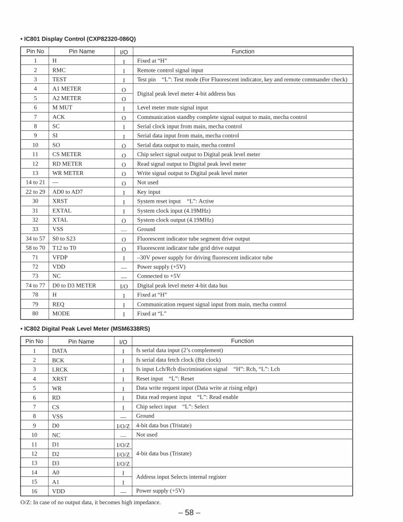
• IC801 Display Control (CXP82320-086Q)
Pin No
1
2
3
4
5
6
7
8
9
10
11
12
13
14
15
16
Pin Name
DATA
BCK
LRCK
XRST
WR
RD
CS
VSS
D0
NC
D1
D2
D3
A0
A1
VDD
• IC802 Digital Peak Level Meter (MSM6338RS)
I/O
I
I
I
I
I
I
I
—
I/O/Z
—
I/O/Z
I/O/Z
I/O/Z
I
I
—
Function
fs serial data input (2’s complement)
fs serial data fetch clock (Bit clock)
fs input Lch/Rch discrimination signal “H”: Rch, “L”: Lch
Reset input “L”: Reset
Data write request input (Data write at rising edge)
Data read request input “L”: Read enable
Chip select input “L”: Select
Ground
4-bit data bus (Tristate)
Not used
4-bit data bus (Tristate)
Address input Selects internal register
Power supply (+5V)
O/Z: In case of no output data, it becomes high impedance.

– 59 –
SECTION 6EXPLODED VIEWS
6-1. CASE AND BACK PANEL SECTION
NOTE:• -XX, -X mean standardized parts, so they may have
some difference from the original one.• Items marked “*” are not stocked since they are
seldom required for routine service. Some delayshould be anticipated when ordering these items.
• The mechanical parts with no reference number inthe exploded views are not supplied.
• Hardware (# mark) list and accessories and pack-ing materials are given in the last of this parts list.
• AbbreviationCND : Canadian model
The components identified bymark ! or dotted line with mark! are critical for safety.Replace only with part numberspecified.
Les composants identifiés par unemarque ! sont critiques pour lasécurité.Ne les remplacer que par unepiéce portant le numéro spécifié.
Ref. No. Part No. Description Remark Ref. No. Part No. Description Remark
* 1 3-350-407-41 CASE* 2 1-661-402-11 COAX I/O BOARD* 3 1-661-406-11 IL COVER BOARD
4 3-704-366-21 SCREW (CASE)(M3X10)* 5 3-018-941-01 PANEL, BACK (US,CND)
* 5 3-018-941-11 PANEL, BACK (AEP,UK)* 6 1-661-405-11 INLET BOARD
7 4-956-885-01 FOOT (F58175S2W)8 3-703-685-21 SCREW (+BV 3X8)! IL001 1-251-234-11 INLET, AC
14
2
5
7
4
3
6
7
8
not supplied
FRONT PANEL
#25
#23
#22
#22
#24
#24
#24
IL001

– 60 –
6-2. FRONT PANEL SECTION
Ref. No. Part No. Description Remark Ref. No. Part No. Description Remark
51 4-908-848-31 EMBLEM, SONY52 3-018-940-01 PANEL, FRONT53 3-382-635-01 KNOB (REC-R)54 3-356-957-01 SPRING55 3-382-634-01 KNOB (REC-L)
56 3-382-627-01 SPRING, RING57 3-922-823-21 ESCUTCHEON (R)58 3-922-822-11 ESCUTCHEON (L)59 3-922-932-01 WINDOW (FL TUBE)60 3-922-824-21 BUTTON (1)
61 3-922-825-21 BUTTON (2)62 3-922-826-21 BUTTON (3)63 3-922-827-21 BUTTON (4)64 4-922-518-01 KNOB (TIMER)65 4-969-185-01 WINDOW (REMOTE CONTROL)
* 66 A-2007-739-A DISPLAY BOARD, COMPLETE* 67 1-661-399-11 REMOCON BOARD* 68 1-661-400-11 REC VOL BOARD
69 4-922-921-21 BUTTON (POWER)70 1-775-464-11 WIRE (FLAT TYPE)(17 CORE)
71 3-917-216-02 KNOB (TIMER)* 72 4-932-810-11 CUSHION (FL)* 73 4-947-170-01 HOLDER* 74 1-661-403-11 AC SW BOARD* 75 1-661-404-11 SW COVER BOARD
76 3-831-441-99 CUSHION, SPEAKERFL801 1-517-382-11 INDICATOR TUBE, FLUORESCENTRV101 1-241-937-11 RES, VAR, CARBON 20K/20K!S001 1-572-267-51 SWITCH, PUSH (AC POWER)(1 KEY)(POWER)
51
69
7475
59
64
6063 70
52
53 5455 56 57
61
65
76
58
72
73
66
67
6871
62#3
#19
#3
#4
not supplied
Supplied with RV101
RV101
S001
FL801
Les composants identifiés parune marque ! sont critiques pourla sécurité.Ne les remplacer que par unepiéce portant le numéro spécifié.
The components identified bymark ! or dotted line with mark! are critical for safety.Replace only with part numberspecified.

– 61 –
6-3. CHASSIS SECTION
Ref. No. Part No. Description Remark Ref. No. Part No. Description Remark
* 101 A-2007-737-A MAIN BOARD, COMPLETE (US,CND)* 101 A-2007-740-A MAIN BOARD, COMPLETE (AEP,UK)* 102 1-661-401-11 PRIMARY BOARD* 103 1-656-335-11 SBM DF BOARD* 104 1-656-334-11 HEADPHONE BOARD
105 X-3362-818-1 KNOB (DIA. 12) ASSY (B), FLAT106 1-775-389-11 WIRE (FLAT TYPE)(31 CORE)
* 107 3-670-570-00 SPACER, SUPPORT108 4-924-098-01 HOLDER, PC BOARD109 X-3374-441-1 PANEL (CASSETTE) ASSY
110 4-886-821-11 SCREW, S TIGHT, +PTTWH 3X6111 3-701-418-00 WASHER, SPECIAL!T901 1-427-889-11 TRANSFORMER, POWER (US,CND)!T901 1-427-890-11 TRANSFORMER, POWER (AEP,UK)
Les composants identifiés parune marque ! sont critiques pourla sécurité.Ne les remplacer que par unepiéce portant le numéro spécifié.
The components identified bymark ! or dotted line with mark! are critical for safety.Replace only with part numberspecified.
109
110
105
108
104
108108
107
107
103
101
102
111
106
not supplied
Suppliedwith RV651
MECHANISM DECK
Supplied with J601
#4
#4
T901
#4
– 62 –
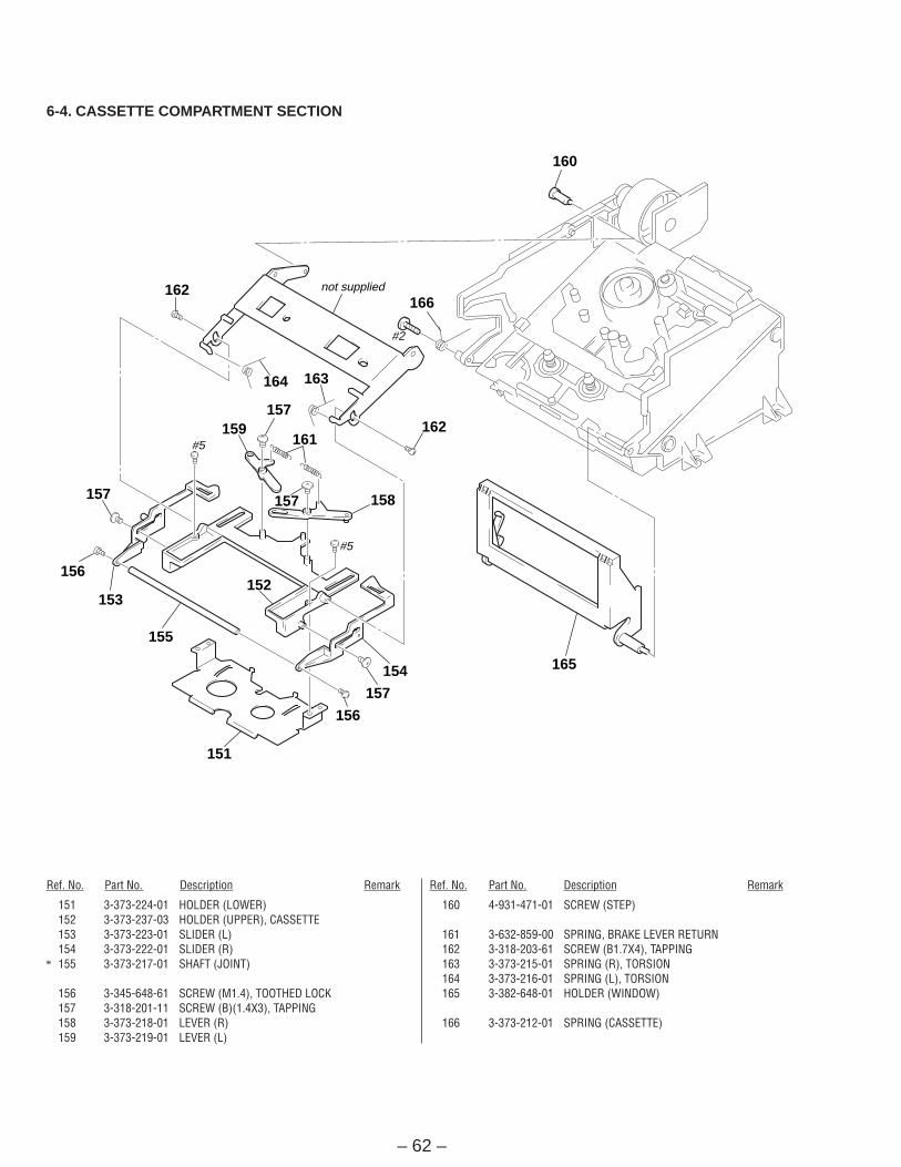
6-4. CASSETTE COMPARTMENT SECTION
Ref. No. Part No. Description Remark Ref. No. Part No. Description Remark
151 3-373-224-01 HOLDER (LOWER)152 3-373-237-03 HOLDER (UPPER), CASSETTE153 3-373-223-01 SLIDER (L)154 3-373-222-01 SLIDER (R)
* 155 3-373-217-01 SHAFT (JOINT)
156 3-345-648-61 SCREW (M1.4), TOOTHED LOCK157 3-318-201-11 SCREW (B)(1.4X3), TAPPING158 3-373-218-01 LEVER (R)159 3-373-219-01 LEVER (L)
160 4-931-471-01 SCREW (STEP)
161 3-632-859-00 SPRING, BRAKE LEVER RETURN162 3-318-203-61 SCREW (B1.7X4), TAPPING163 3-373-215-01 SPRING (R), TORSION164 3-373-216-01 SPRING (L), TORSION165 3-382-648-01 HOLDER (WINDOW)
166 3-373-212-01 SPRING (CASSETTE)
160
166not supplied
#2
#5
#5
163164
157159
157 158
162161
162
152
155
153
156
157
151
156
157
154 165
– 63 –
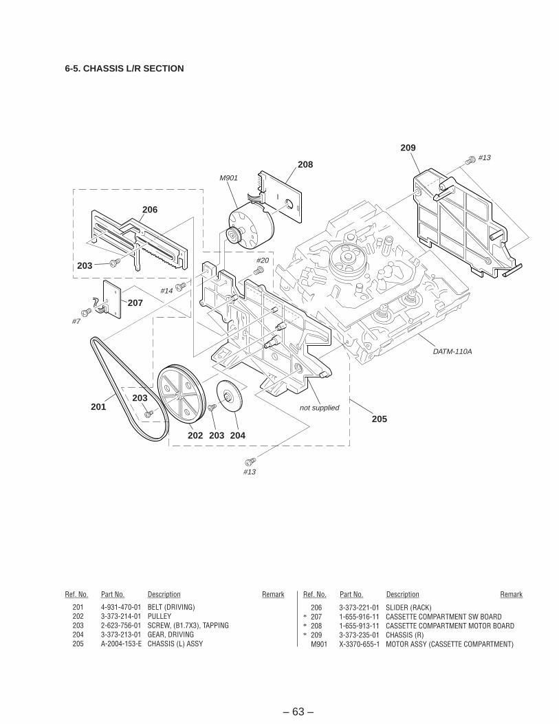
6-5. CHASSIS L/R SECTION
Ref. No. Part No. Description Remark Ref. No. Part No. Description Remark
201 4-931-470-01 BELT (DRIVING)202 3-373-214-01 PULLEY203 2-623-756-01 SCREW, (B1.7X3), TAPPING204 3-373-213-01 GEAR, DRIVING205 A-2004-153-E CHASSIS (L) ASSY
206 3-373-221-01 SLIDER (RACK)* 207 1-655-916-11 CASSETTE COMPARTMENT SW BOARD* 208 1-655-913-11 CASSETTE COMPARTMENT MOTOR BOARD* 209 3-373-235-01 CHASSIS (R)
M901 X-3370-655-1 MOTOR ASSY (CASSETTE COMPARTMENT)
209
208
203
206
207
203201
202 203 204
205
M901
#13
DATM-110A
not supplied
#13
#7
#14
#20
– 64 –
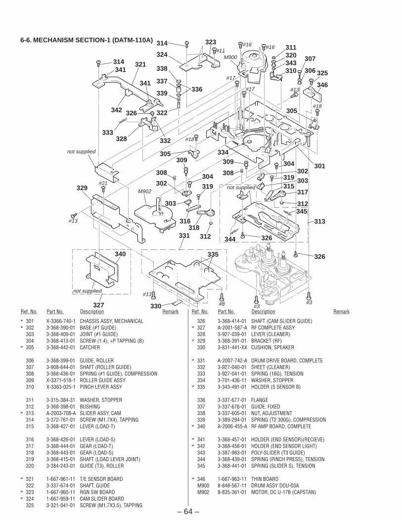
6-6. MECHANISM SECTION-1 (DATM-110A)
Ref. No. Part No. Description Remark Ref. No. Part No. Description Remark
* 301 X-3366-740-1 CHASSIS ASSY, MECHANICAL* 302 3-368-390-01 BASE (#1 GUIDE)
303 3-368-409-01 JOINT (#1 GUIDE)304 3-368-413-01 SCREW (1.4), +P TAPPING (B)
* 305 3-368-442-01 CATCHER
306 3-368-399-01 GUIDE, ROLLER307 3-908-644-01 SHAFT (ROLLER GUIDE)308 3-368-436-01 SPRING (#1 GUIDE), COMPRESSION309 X-3371-518-1 ROLLER GUIDE ASSY310 X-3363-025-1 PINCH LEVER ASSY
311 3-315-384-31 WASHER, STOPPER312 3-368-398-01 BUSHING
* 313 A-2003-708-A SLIDER ASSY, CAM314 3-372-761-01 SCREW (M1.7X4), TAPPING315 3-368-427-01 LEVER (LOAD-T)
316 3-368-426-01 LEVER (LOAD-S)317 3-368-444-01 GEAR (LOAD-T)318 3-368-443-01 GEAR (LOAD-S)319 3-368-415-01 SHAFT (LOAD LEVER JOINT)320 3-384-243-01 GUIDE (T3), ROLLER
* 321 1-667-961-11 T/E SENSOR BOARD322 3-337-674-01 SHAFT, GUIDE
* 323 1-667-960-11 RGN SW BOARD* 324 1-667-959-11 CAM SLIDER BOARD
325 3-321-041-01 SCREW (M1.7X3.5), TAPPING
326 3-368-414-01 SHAFT (CAM SLIDER GUIDE)* 327 A-2001-587-A RF COMPLETE ASSY
328 3-927-039-01 LEVER (CLEANER)* 329 3-368-391-01 BRACKET (RF)
330 3-831-441-XX CUSHION, SPEAKER
* 331 A-2007-742-A DRUM DRIVE BOARD, COMPLETE332 3-927-040-01 SHEET (CLEANER)333 3-927-041-01 SPRING (16G), TENSION334 3-701-436-11 WASHER, STOPPER
* 335 3-343-491-01 HOLDER (S SENSOR B)
336 3-337-677-01 FLANGE337 3-337-676-01 GUIDE, FIXED338 3-337-605-01 NUT, ADJUSTMENT339 3-389-294-01 SPRING (T2 300G), COMPRESSION
* 340 A-2006-455-A RF AMP BOARD, COMPLETE
* 341 3-368-457-01 HOLDER (END SENSOR)(RECIEVE)* 342 3-368-456-01 HOLDER (END SENSOR LIGHT)
343 3-387-983-01 POLY-SLIDER (T3 GUIDE)344 3-368-439-01 SPRING (PINCH PRESS), TENSION345 3-368-441-01 SPRING (SLIDER S), TENSION
* 346 1-667-963-11 THIN BOARDM900 8-848-567-11 DRUM ASSY DOU-03AM902 8-835-361-01 MOTOR, DC U-17B (CAPSTAN)
#13
#13
#21
not supplied
not supplied
#8 #3#3
M902not supplied
#17
#17
#18
#13
#18
#16#16
M900#11
340
327
335
330
331 312 344
326
318316
319
308
309302
319 303
304309
304
303
329302
308
305
332
315317
312
326
313
345
301
305
306310343320324311
307
346
325
322
328
326
333
321
342
341
339336
337
338
314 323
314
341
334
– 65 –
not supplied
not supplied
not supplied
not supplied
#6
378
379 356
384
372
377
#12
notsupplied
377
374
375376
373364 364
383
355
357
356
354
363356
356
361
360
382
369
368
365
358
386
362
371
353359366381352
380
367351
356
356
367351
370
371
385
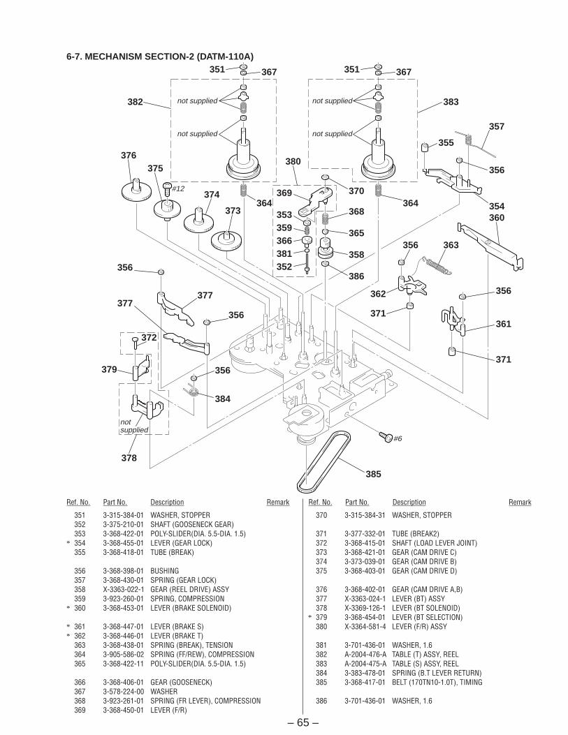
6-7. MECHANISM SECTION-2 (DATM-110A)
Ref. No. Part No. Description Remark Ref. No. Part No. Description Remark
351 3-315-384-01 WASHER, STOPPER352 3-375-210-01 SHAFT (GOOSENECK GEAR)353 3-368-422-01 POLY-SLIDER(DIA. 5.5-DIA. 1.5)
* 354 3-368-455-01 LEVER (GEAR LOCK)355 3-368-418-01 TUBE (BREAK)
356 3-368-398-01 BUSHING357 3-368-430-01 SPRING (GEAR LOCK)358 X-3363-022-1 GEAR (REEL DRIVE) ASSY359 3-923-260-01 SPRING, COMPRESSION
* 360 3-368-453-01 LEVER (BRAKE SOLENOID)
* 361 3-368-447-01 LEVER (BRAKE S)* 362 3-368-446-01 LEVER (BRAKE T)
363 3-368-438-01 SPRING (BREAK), TENSION364 3-905-586-02 SPRING (FF/REW), COMPRESSION365 3-368-422-11 POLY-SLIDER(DIA. 5.5-DIA. 1.5)
366 3-368-406-01 GEAR (GOOSENECK)367 3-578-224-00 WASHER368 3-923-261-01 SPRING (FR LEVER), COMPRESSION369 3-368-450-01 LEVER (F/R)
370 3-315-384-31 WASHER, STOPPER
371 3-377-332-01 TUBE (BREAK2)372 3-368-415-01 SHAFT (LOAD LEVER JOINT)373 3-368-421-01 GEAR (CAM DRIVE C)374 3-373-039-01 GEAR (CAM DRIVE B)375 3-368-403-01 GEAR (CAM DRIVE D)
376 3-368-402-01 GEAR (CAM DRIVE A,B)377 X-3363-024-1 LEVER (BT) ASSY378 X-3369-126-1 LEVER (BT SOLENOID)
* 379 3-368-454-01 LEVER (BT SELECTION)380 X-3364-581-4 LEVER (F/R) ASSY
381 3-701-436-01 WASHER, 1.6382 A-2004-476-A TABLE (T) ASSY, REEL383 A-2004-475-A TABLE (S) ASSY, REEL384 3-383-478-01 SPRING (B.T LEVER RETURN)385 3-368-417-01 BELT (170TN10-1.0T), TIMING
386 3-701-436-01 WASHER, 1.6

– 66 –
6-8. MECHANISM SECTION-3 (DATM-110A)
Ref. No. Part No. Description Remark Ref. No. Part No. Description Remark
408 3-905-867-01 SPRING (STOPPER)* 409 1-667-962-11 REEL MOTOR BOARD
410 3-380-525-01 ARBOR (BT ADJUSTMENT), MAVABLE
M903 X-3363-109-1 MOTOR (CAM) ASSYM905 X-3363-110-2 MOTOR (REEL) ASSYPM903 1-454-732-11 SOLENOID, PLUNGER (BRAKE)PM904 1-454-536-11 SOLENOID, PLUNGER (TENSION)
* 401 A-2004-478-A CHASSIS (REEL) ASSY* 402 X-3366-312-1 CHASSIS ASSY, REEL
403 3-368-431-01 SPRING (B.T SOLENOID)404 2-623-756-01 SCREW, (B1.7X3), TAPPING405 3-368-423-01 SCREW (M2.6), STEP
* 406 3-368-416-01 BRACKET (B.T SOLENOID)407 3-919-599-01 SPACER (P)
M903
#9
409
PM903
PM904
not supplied
not supplied
401
402
#15
403
M905
#10
#14
#11407
408
410
406405
404
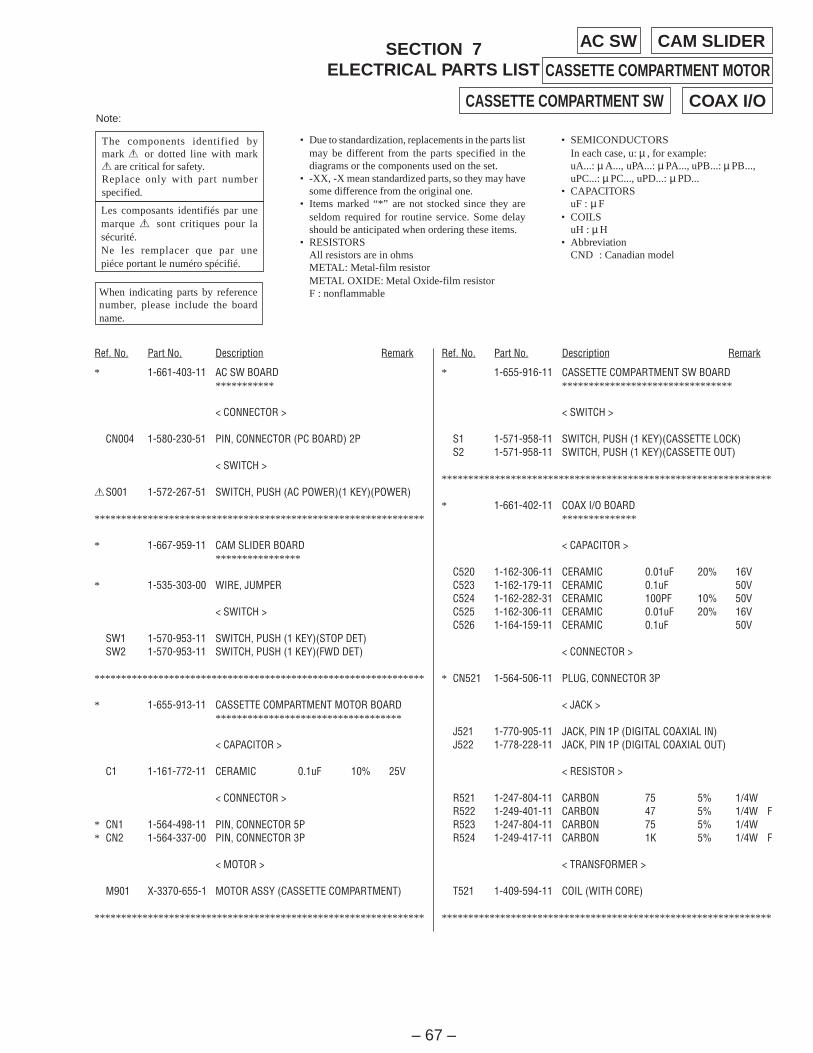
– 67 –
• SEMICONDUCTORSIn each case, u: µ , for example:uA...: µ A..., uPA...: µ PA..., uPB...: µ PB...,uPC...: µ PC..., uPD...: µ PD...
• CAPACITORSuF : µ F
• COILSuH : µ H
• AbbreviationCND : Canadian model
• Due to standardization, replacements in the parts listmay be different from the parts specified in thediagrams or the components used on the set.
• -XX, -X mean standardized parts, so they may havesome difference from the original one.
• Items marked “*” are not stocked since they areseldom required for routine service. Some delayshould be anticipated when ordering these items.
• RESISTORSAll resistors are in ohmsMETAL: Metal-film resistorMETAL OXIDE: Metal Oxide-film resistorF : nonflammable
Note:
Les composants identifiés par unemarque ! sont critiques pour lasécurité.Ne les remplacer que par unepiéce portant le numéro spécifié.
The components identified bymark ! or dotted line with mark! are critical for safety.Replace only with part numberspecified.
When indicating parts by referencenumber, please include the boardname.
Ref. No. Part No. Description Remark Ref. No. Part No. Description Remark
CAM SLIDERSECTION 7ELECTRICAL PARTS LIST
AC SW
CASSETTE COMPARTMENT MOTOR
* 1-661-403-11 AC SW BOARD***********
< CONNECTOR >
CN004 1-580-230-51 PIN, CONNECTOR (PC BOARD) 2P
< SWITCH >
!S001 1-572-267-51 SWITCH, PUSH (AC POWER)(1 KEY)(POWER)
**************************************************************
* 1-667-959-11 CAM SLIDER BOARD****************
* 1-535-303-00 WIRE, JUMPER
< SWITCH >
SW1 1-570-953-11 SWITCH, PUSH (1 KEY)(STOP DET)SW2 1-570-953-11 SWITCH, PUSH (1 KEY)(FWD DET)
**************************************************************
* 1-655-913-11 CASSETTE COMPARTMENT MOTOR BOARD***********************************
< CAPACITOR >
C1 1-161-772-11 CERAMIC 0.1uF 10% 25V
< CONNECTOR >
* CN1 1-564-498-11 PIN, CONNECTOR 5P* CN2 1-564-337-00 PIN, CONNECTOR 3P
< MOTOR >
M901 X-3370-655-1 MOTOR ASSY (CASSETTE COMPARTMENT)
**************************************************************
* 1-655-916-11 CASSETTE COMPARTMENT SW BOARD********************************
< SWITCH >
S1 1-571-958-11 SWITCH, PUSH (1 KEY)(CASSETTE LOCK)S2 1-571-958-11 SWITCH, PUSH (1 KEY)(CASSETTE OUT)
**************************************************************
* 1-661-402-11 COAX I/O BOARD**************
< CAPACITOR >
C520 1-162-306-11 CERAMIC 0.01uF 20% 16VC523 1-162-179-11 CERAMIC 0.1uF 50VC524 1-162-282-31 CERAMIC 100PF 10% 50VC525 1-162-306-11 CERAMIC 0.01uF 20% 16VC526 1-164-159-11 CERAMIC 0.1uF 50V
< CONNECTOR >
* CN521 1-564-506-11 PLUG, CONNECTOR 3P
< JACK >
J521 1-770-905-11 JACK, PIN 1P (DIGITAL COAXIAL IN)J522 1-778-228-11 JACK, PIN 1P (DIGITAL COAXIAL OUT)
< RESISTOR >
R521 1-247-804-11 CARBON 75 5% 1/4WR522 1-249-401-11 CARBON 47 5% 1/4W FR523 1-247-804-11 CARBON 75 5% 1/4WR524 1-249-417-11 CARBON 1K 5% 1/4W F
< TRANSFORMER >
T521 1-409-594-11 COIL (WITH CORE)
**************************************************************
CASSETTE COMPARTMENT SW COAX I/O

– 68 –
Ref. No. Part No. Description Remark Ref. No. Part No. Description Remark
* A-2007-739-A DISPLAY BOARD, COMPLETE************************
* 4-932-810-11 CUSHION (FL)* 4-947-170-01 HOLDER
< CAPACITOR >
C881 1-164-096-11 CERAMIC 0.01uF 50VC882 1-164-096-11 CERAMIC 0.01uF 50VC883 1-164-096-11 CERAMIC 0.01uF 50VC884 1-126-177-11 ELECT 100uF 20% 10VC885 1-164-096-11 CERAMIC 0.01uF 50V
C886 1-164-096-11 CERAMIC 0.01uF 50V
< CONNECTOR >
CN801 1-568-860-11 SOCKET, CONNECTOR 17P
< COMPOSITION CIRCUIT BLOCK >
CP801 1-233-566-11 COMPOSITION CIRCUIT BLOCKCP802 1-233-566-11 COMPOSITION CIRCUIT BLOCKCP803 1-233-566-11 COMPOSITION CIRCUIT BLOCKCP804 1-233-566-11 COMPOSITION CIRCUIT BLOCK
< FLUORESCENT INDICATOR >
FL801 1-517-382-11 INDICATOR TUBE, FLUORESCENT
< IC >
IC801 8-752-890-04 IC CXP82320-086QIC802 8-759-995-09 IC MSM6338RS
< TRANSISTOR >
Q801 8-729-620-05 TRANSISTOR 2SC2603-EFQ802 8-729-620-05 TRANSISTOR 2SC2603-EFQ803 8-729-620-05 TRANSISTOR 2SC2603-EF
< RESISTOR >
R801 1-249-427-11 CARBON 6.8K 5% 1/4W FR802 1-249-415-11 CARBON 680 5% 1/4W FR803 1-249-417-11 CARBON 1K 5% 1/4W FR804 1-249-419-11 CARBON 1.5K 5% 1/4W FR805 1-247-843-11 CARBON 3.3K 5% 1/4W
R806 1-249-425-11 CARBON 4.7K 5% 1/4W FR807 1-249-429-11 CARBON 10K 5% 1/4WR811 1-249-427-11 CARBON 6.8K 5% 1/4W FR812 1-249-415-11 CARBON 680 5% 1/4W FR813 1-249-417-11 CARBON 1K 5% 1/4W F
R814 1-249-419-11 CARBON 1.5K 5% 1/4W FR815 1-247-843-11 CARBON 3.3K 5% 1/4WR817 1-249-431-11 CARBON 15K 5% 1/4WR818 1-249-435-11 CARBON 33K 5% 1/4WR821 1-249-427-11 CARBON 6.8K 5% 1/4W F
R831 1-249-427-11 CARBON 6.8K 5% 1/4W FR841 1-249-437-11 CARBON 47K 5% 1/4WR851 1-249-427-11 CARBON 6.8K 5% 1/4W FR861 1-249-437-11 CARBON 47K 5% 1/4WR871 1-249-437-11 CARBON 47K 5% 1/4W
R881 1-249-417-11 CARBON 1K 5% 1/4W FR882 1-249-437-11 CARBON 47K 5% 1/4WR883 1-249-437-11 CARBON 47K 5% 1/4WR884 1-249-437-11 CARBON 47K 5% 1/4WR885 1-249-437-11 CARBON 47K 5% 1/4W
R886 1-249-437-11 CARBON 47K 5% 1/4WR887 1-249-417-11 CARBON 1K 5% 1/4W FR888 1-249-437-11 CARBON 47K 5% 1/4WR889 1-249-437-11 CARBON 47K 5% 1/4WR890 1-249-429-11 CARBON 10K 5% 1/4W
R891 1-249-429-11 CARBON 10K 5% 1/4W
< SWITCH >
S802 1-554-937-11 SWITCH, KEY BOARD (STOP p)S803 1-554-937-11 SWITCH, KEY BOARD (PLAY ()S804 1-554-937-11 SWITCH, KEY BOARD (AMS, SELECT, =)S805 1-554-937-11 SWITCH, KEY BOARD (AMS, SELECT, +)S806 1-554-937-11 SWITCH, KEY BOARD (MODE, MENU)
S807 1-554-937-11 SWITCH, KEY BOARD (RESET, ENTER)S811 1-554-937-11 SWITCH, KEY BOARD (DATA, REW 0)S812 1-554-937-11 SWITCH, KEY BOARD (DATA, FF ))S813 1-554-937-11 SWITCH, KEY BOARD (REC r)S814 1-554-937-11 SWITCH, KEY BOARD (PAUSE P)
S815 1-554-937-11 SWITCH, KEY BOARD (REC MUTE R)S817 1-571-520-11 SWITCH, SLIDE (INPUT)
< VIBRATOR >
X801 1-577-359-21 VIBRATOR, CERAMIC (4.19MHz)
**************************************************************
* A-2007-742-A DRUM DRIVE BOARD, COMPLETE***************************
* 3-343-491-01 HOLDER (S SENSOR B)
< CAPACITOR >
C01 1-126-176-11 ELECT 220uF 20% 10VC02 1-126-177-11 ELECT 100uF 20% 10VC03 1-126-301-11 ELECT 1uF 20% 50VC04 1-164-161-11 CERAMIC CHIP 0.0022uF 10% 100VC05 1-163-017-00 CERAMIC CHIP 0.0047uF 5% 50V
C08 1-163-001-11 CERAMIC CHIP 220PF 10% 50VC10 1-164-232-11 CERAMIC CHIP 0.01uF 50VC11 1-164-161-11 CERAMIC CHIP 0.0022uF 10% 100VC12 1-163-038-91 CERAMIC CHIP 0.1uF 25VC21 1-163-001-11 CERAMIC CHIP 220PF 10% 50V
DISPLAY DRUM DRIVE
– 69 –
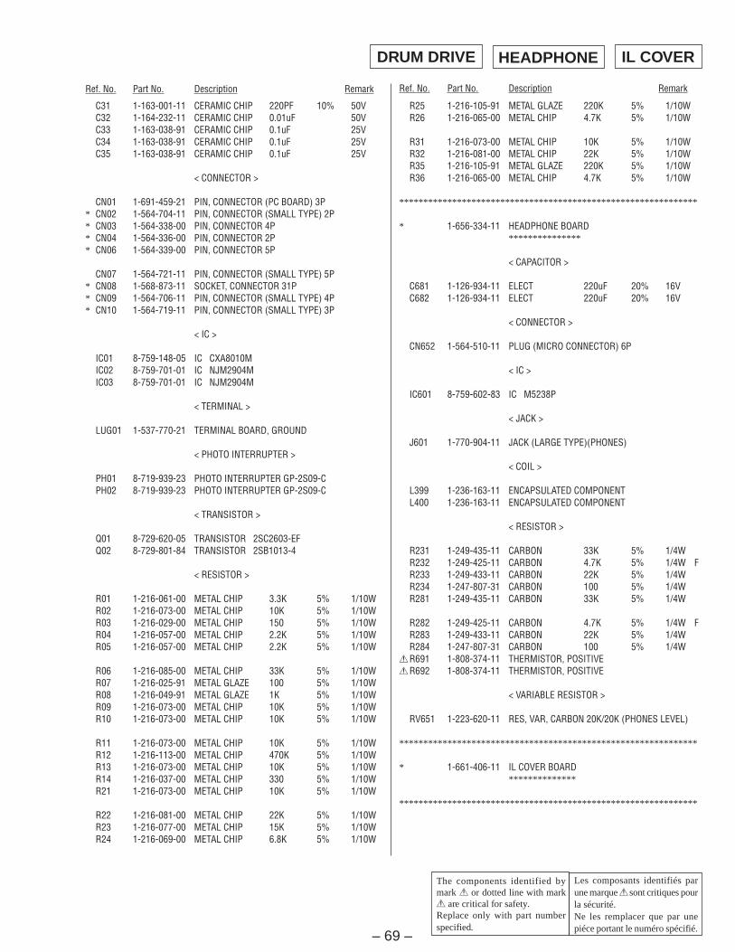
Ref. No. Part No. Description Remark Ref. No. Part No. Description Remark
C31 1-163-001-11 CERAMIC CHIP 220PF 10% 50VC32 1-164-232-11 CERAMIC CHIP 0.01uF 50VC33 1-163-038-91 CERAMIC CHIP 0.1uF 25VC34 1-163-038-91 CERAMIC CHIP 0.1uF 25VC35 1-163-038-91 CERAMIC CHIP 0.1uF 25V
< CONNECTOR >
CN01 1-691-459-21 PIN, CONNECTOR (PC BOARD) 3P* CN02 1-564-704-11 PIN, CONNECTOR (SMALL TYPE) 2P* CN03 1-564-338-00 PIN, CONNECTOR 4P* CN04 1-564-336-00 PIN, CONNECTOR 2P* CN06 1-564-339-00 PIN, CONNECTOR 5P
CN07 1-564-721-11 PIN, CONNECTOR (SMALL TYPE) 5P* CN08 1-568-873-11 SOCKET, CONNECTOR 31P* CN09 1-564-706-11 PIN, CONNECTOR (SMALL TYPE) 4P* CN10 1-564-719-11 PIN, CONNECTOR (SMALL TYPE) 3P
< IC >
IC01 8-759-148-05 IC CXA8010MIC02 8-759-701-01 IC NJM2904MIC03 8-759-701-01 IC NJM2904M
< TERMINAL >
LUG01 1-537-770-21 TERMINAL BOARD, GROUND
< PHOTO INTERRUPTER >
PH01 8-719-939-23 PHOTO INTERRUPTER GP-2S09-CPH02 8-719-939-23 PHOTO INTERRUPTER GP-2S09-C
< TRANSISTOR >
Q01 8-729-620-05 TRANSISTOR 2SC2603-EFQ02 8-729-801-84 TRANSISTOR 2SB1013-4
< RESISTOR >
R01 1-216-061-00 METAL CHIP 3.3K 5% 1/10WR02 1-216-073-00 METAL CHIP 10K 5% 1/10WR03 1-216-029-00 METAL CHIP 150 5% 1/10WR04 1-216-057-00 METAL CHIP 2.2K 5% 1/10WR05 1-216-057-00 METAL CHIP 2.2K 5% 1/10W
R06 1-216-085-00 METAL CHIP 33K 5% 1/10WR07 1-216-025-91 METAL GLAZE 100 5% 1/10WR08 1-216-049-91 METAL GLAZE 1K 5% 1/10WR09 1-216-073-00 METAL CHIP 10K 5% 1/10WR10 1-216-073-00 METAL CHIP 10K 5% 1/10W
R11 1-216-073-00 METAL CHIP 10K 5% 1/10WR12 1-216-113-00 METAL CHIP 470K 5% 1/10WR13 1-216-073-00 METAL CHIP 10K 5% 1/10WR14 1-216-037-00 METAL CHIP 330 5% 1/10WR21 1-216-073-00 METAL CHIP 10K 5% 1/10W
R22 1-216-081-00 METAL CHIP 22K 5% 1/10WR23 1-216-077-00 METAL CHIP 15K 5% 1/10WR24 1-216-069-00 METAL CHIP 6.8K 5% 1/10W
R25 1-216-105-91 METAL GLAZE 220K 5% 1/10WR26 1-216-065-00 METAL CHIP 4.7K 5% 1/10W
R31 1-216-073-00 METAL CHIP 10K 5% 1/10WR32 1-216-081-00 METAL CHIP 22K 5% 1/10WR35 1-216-105-91 METAL GLAZE 220K 5% 1/10WR36 1-216-065-00 METAL CHIP 4.7K 5% 1/10W
**************************************************************
* 1-656-334-11 HEADPHONE BOARD***************
< CAPACITOR >
C681 1-126-934-11 ELECT 220uF 20% 16VC682 1-126-934-11 ELECT 220uF 20% 16V
< CONNECTOR >
CN652 1-564-510-11 PLUG (MICRO CONNECTOR) 6P
< IC >
IC601 8-759-602-83 IC M5238P
< JACK >
J601 1-770-904-11 JACK (LARGE TYPE)(PHONES)
< COIL >
L399 1-236-163-11 ENCAPSULATED COMPONENTL400 1-236-163-11 ENCAPSULATED COMPONENT
< RESISTOR >
R231 1-249-435-11 CARBON 33K 5% 1/4WR232 1-249-425-11 CARBON 4.7K 5% 1/4W FR233 1-249-433-11 CARBON 22K 5% 1/4WR234 1-247-807-31 CARBON 100 5% 1/4WR281 1-249-435-11 CARBON 33K 5% 1/4W
R282 1-249-425-11 CARBON 4.7K 5% 1/4W FR283 1-249-433-11 CARBON 22K 5% 1/4WR284 1-247-807-31 CARBON 100 5% 1/4W!R691 1-808-374-11 THERMISTOR, POSITIVE!R692 1-808-374-11 THERMISTOR, POSITIVE
< VARIABLE RESISTOR >
RV651 1-223-620-11 RES, VAR, CARBON 20K/20K (PHONES LEVEL)
**************************************************************
* 1-661-406-11 IL COVER BOARD**************
**************************************************************
HEADPHONEDRUM DRIVE IL COVER
Les composants identifiés parune marque ! sont critiques pourla sécurité.Ne les remplacer que par unepiéce portant le numéro spécifié.
The components identified bymark ! or dotted line with mark! are critical for safety.Replace only with part numberspecified.

– 70 –
Ref. No. Part No. Description Remark Ref. No. Part No. Description Remark
* 1-661-405-11 INLET BOARD***********
< CONNECTOR >
CN900 1-775-047-11 CORD (WITH CONNECTOR)
< INLET >
! IL001 1-251-234-11 INLET, AC (~ AC IN)
**************************************************************
* A-2007-737-A MAIN BOARD, COMPLETE (US,CND)******************************
* A-2007-740-A MAIN BOARD, COMPLETE (AEP,UK)******************************
* 1-533-213-31 HOLDER, FUSE
< CAPACITOR >
C101 1-126-933-11 ELECT 100uF 20% 10VC102 1-162-286-31 CERAMIC 220PF 10% 50VC103 1-126-933-11 ELECT 100uF 20% 10VC107 1-130-481-00 MYLAR 0.0068uF 5% 50VC151 1-126-933-11 ELECT 100uF 20% 10V
C152 1-162-286-31 CERAMIC 220PF 10% 50VC153 1-126-933-11 ELECT 100uF 20% 10VC157 1-130-481-00 MYLAR 0.0068uF 5% 50VC201 1-130-471-00 MYLAR 0.001uF 5% 50VC202 1-110-341-11 MYLAR 330PF 5% 50V
C203 1-110-341-11 MYLAR 330PF 5% 50VC204 1-130-471-00 MYLAR 0.001uF 5% 50VC205 1-130-479-00 MYLAR 0.0047uF 5% 50VC206 1-126-933-11 ELECT 100uF 20% 10VC207 1-162-302-11 CERAMIC 0.0022uF 30% 16V
C251 1-130-471-00 MYLAR 0.001uF 5% 50VC252 1-110-341-11 MYLAR 330PF 5% 50VC253 1-110-341-11 MYLAR 330PF 5% 50VC254 1-130-471-00 MYLAR 0.001uF 5% 50VC255 1-130-479-00 MYLAR 0.0047uF 5% 50V
C256 1-126-933-11 ELECT 100uF 20% 10VC257 1-162-302-11 CERAMIC 0.0022uF 30% 16VC302 1-162-197-31 CERAMIC 6.8PF 10% 50VC304 1-126-960-11 ELECT 1uF 20% 50VC307 1-164-159-11 CERAMIC 0.1uF 50V
C308 1-162-294-31 CERAMIC 0.001uF 10% 50VC309 1-126-935-11 ELECT 470uF 20% 6.3VC310 1-164-159-11 CERAMIC 0.1uF 50VC311 1-162-198-31 CERAMIC 8.2PF 10% 50VC312 1-162-199-31 CERAMIC 10PF 5% 50V
C313 1-162-197-31 CERAMIC 6.8PF 10% 50VC314 1-162-197-31 CERAMIC 6.8PF 10% 50VC327 1-162-198-31 CERAMIC 8.2PF 10% 50V
C332 1-164-159-11 CERAMIC 0.1uF 50VC333 1-162-211-31 CERAMIC 33PF 5% 50V
C334 1-126-964-11 ELECT 10uF 20% 50VC335 1-162-306-11 CERAMIC 0.01uF 20% 16VC336 1-164-159-11 CERAMIC 0.1uF 50VC337 1-164-159-11 CERAMIC 0.1uF 50VC338 1-164-159-11 CERAMIC 0.1uF 50V
C340 1-164-159-11 CERAMIC 0.1uF 50VC341 1-164-159-11 CERAMIC 0.1uF 50VC342 1-126-935-11 ELECT 470uF 20% 6.3VC343 1-162-294-31 CERAMIC 0.001uF 10% 50VC344 1-162-294-31 CERAMIC 0.001uF 10% 50V
C345 1-162-294-31 CERAMIC 0.001uF 10% 50VC351 1-162-306-11 CERAMIC 0.01uF 20% 16VC352 1-162-306-11 CERAMIC 0.01uF 20% 16VC353 1-162-294-31 CERAMIC 0.001uF 10% 50VC354 1-164-159-11 CERAMIC 0.1uF 50V
C355 1-164-159-11 CERAMIC 0.1uF 50VC356 1-164-159-11 CERAMIC 0.1uF 50VC361 1-162-302-11 CERAMIC 0.0022uF 30% 16VC362 1-162-302-11 CERAMIC 0.0022uF 30% 16VC431 1-162-302-11 CERAMIC 0.0022uF 30% 16V
C432 1-162-302-11 CERAMIC 0.0022uF 30% 16VC433 1-162-286-31 CERAMIC 220PF 10% 50VC439 1-162-306-11 CERAMIC 0.01uF 20% 16VC441 1-162-302-11 CERAMIC 0.0022uF 30% 16VC442 1-162-302-11 CERAMIC 0.0022uF 30% 16V
C443 1-162-286-31 CERAMIC 220PF 10% 50VC444 1-126-964-11 ELECT 10uF 20% 50VC445 1-162-306-11 CERAMIC 0.01uF 20% 16VC451 1-162-306-11 CERAMIC 0.01uF 20% 16VC452 1-126-963-11 ELECT 4.7uF 20% 50V
C453 1-126-338-11 ELECT 47uF 20% 63VC454 1-162-306-11 CERAMIC 0.01uF 20% 16VC459 1-162-306-11 CERAMIC 0.01uF 20% 16VC471 1-162-306-11 CERAMIC 0.01uF 20% 16VC481 1-162-306-11 CERAMIC 0.01uF 20% 16V
C491 1-162-290-31 CERAMIC 470PF 10% 50VC492 1-162-306-11 CERAMIC 0.01uF 20% 16VC502 1-162-294-31 CERAMIC 0.001uF 10% 50VC503 1-162-284-31 CERAMIC 150PF 10% 50VC507 1-130-481-00 MYLAR 0.0068uF 5% 50V
C509 1-164-159-11 CERAMIC 0.1uF 50VC511 1-164-159-11 CERAMIC 0.1uF 50VC515 1-136-169-00 FILM 0.22uF 5% 50VC527 1-164-159-11 CERAMIC 0.1uF 50VC601 1-136-165-00 FILM 0.1uF 5% 50V
C602 1-136-165-00 FILM 0.1uF 5% 50VC621 1-126-964-11 ELECT 10uF 20% 50VC622 1-126-964-11 ELECT 10uF 20% 50VC623 1-136-165-00 FILM 0.1uF 5% 50VC624 1-136-165-00 FILM 0.1uF 5% 50V
MAIN
Les composants identifiés parune marque ! sont critiques pourla sécurité.Ne les remplacer que par unepiéce portant le numéro spécifié.
The components identified bymark ! or dotted line with mark! are critical for safety.Replace only with part numberspecified.
INLET

– 71 –
Ref. No. Part No. Description Remark Ref. No. Part No. Description Remark
C625 1-136-165-00 FILM 0.1uF 5% 50VC626 1-136-165-00 FILM 0.1uF 5% 50VC627 1-126-935-11 ELECT 470uF 20% 6.3VC628 1-126-935-11 ELECT 470uF 20% 6.3VC630 1-126-935-11 ELECT 470uF 20% 6.3V
C651 1-136-165-00 FILM 0.1uF 5% 50VC652 1-136-165-00 FILM 0.1uF 5% 50VC653 1-136-165-00 FILM 0.1uF 5% 50VC654 1-136-165-00 FILM 0.1uF 5% 50VC661 1-136-165-00 FILM 0.1uF 5% 50V
C662 1-136-165-00 FILM 0.1uF 5% 50VC663 1-136-165-00 FILM 0.1uF 5% 50VC664 1-136-165-00 FILM 0.1uF 5% 50VC665 1-136-165-00 FILM 0.1uF 5% 50VC666 1-136-165-00 FILM 0.1uF 5% 50V
C667 1-136-165-00 FILM 0.1uF 5% 50VC668 1-126-933-11 ELECT 100uF 20% 10VC669 1-136-165-00 FILM 0.1uF 5% 50VC670 1-126-933-11 ELECT 100uF 20% 10VC671 1-126-933-11 ELECT 100uF 20% 10V
C672 1-136-165-00 FILM 0.1uF 5% 50VC673 1-126-933-11 ELECT 100uF 20% 10VC674 1-136-165-00 FILM 0.1uF 5% 50VC675 1-136-165-00 FILM 0.1uF 5% 50VC683 1-136-165-00 FILM 0.1uF 5% 50V
C684 1-126-935-11 ELECT 470uF 20% 6.3VC901 1-126-953-11 ELECT 2200uF 20% 35VC902 1-126-939-11 ELECT 10000uF 20% 16VC903 1-126-935-11 ELECT 470uF 20% 6.3VC904 1-126-916-11 ELECT 1000uF 20% 6.3V
C905 1-128-553-11 ELECT 220uF 20% 63VC906 1-126-968-11 ELECT 100uF 20% 50VC907 1-162-306-11 CERAMIC 0.01uF 20% 16VC908 1-162-306-11 CERAMIC 0.01uF 20% 16VC910 1-128-548-11 ELECT 4700uF 20% 25V
C911 1-126-960-11 ELECT 1uF 20% 50VC912 1-126-767-11 ELECT 1000uF 20% 16VC913 1-162-306-11 CERAMIC 0.01uF 20% 16VC920 1-128-548-11 ELECT 4700uF 20% 25VC921 1-162-306-11 CERAMIC 0.01uF 20% 16V
C922 1-126-767-11 ELECT 1000uF 20% 16VC923 1-162-306-11 CERAMIC 0.01uF 20% 16VC931 1-126-934-11 ELECT 220uF 20% 16VC932 1-164-159-11 CERAMIC 0.1uF 50VC933 1-126-935-11 ELECT 470uF 20% 6.3V
C934 1-136-165-00 FILM 0.1uF 5% 50VC998 1-164-159-11 CERAMIC 0.1uF 50VC999 1-164-159-11 CERAMIC 0.1uF 50V
< CONNECTOR >
* CN301 1-564-706-31 PIN, CONNECTOR (SMALL TYPE) 4P* CN302 1-568-845-11 SOCKET, CONNECTOR 31P
* CN303 1-568-836-11 SOCKET, CONNECTOR 17PCN341 1-770-164-11 PIN, CONNECTOR (PC BOARD) 15P
* CN401 1-564-339-00 PIN, CONNECTOR 5P
* CN601 1-564-708-11 PIN, CONNECTOR (SMALL TYPE) 6PCN651 1-564-510-11 PLUG (MICRO CONNECTOR) 6PCN691 1-573-095-11 SOCKET, CONNECTOR 15PCN901 1-691-767-11 PLUG (MICRO CONNECTOR) 5PCN902 1-691-768-11 PLUG (MICRO CONNECTOR) 6P
< DIODE >
D101 8-719-987-63 DIODE 1N4148MD102 8-719-987-63 DIODE 1N4148MD103 8-719-987-63 DIODE 1N4148MD104 8-719-987-63 DIODE 1N4148MD151 8-719-987-63 DIODE 1N4148M
D152 8-719-987-63 DIODE 1N4148MD153 8-719-987-63 DIODE 1N4148MD154 8-719-987-63 DIODE 1N4148MD321 8-719-987-63 DIODE 1N4148MD331 8-719-987-63 DIODE 1N4148M
D333 8-719-987-63 DIODE 1N4148MD411 8-719-200-82 DIODE 11ES2D412 8-719-200-82 DIODE 11ES2D413 8-719-200-82 DIODE 11ES2D421 8-719-200-82 DIODE 11ES2
D422 8-719-200-82 DIODE 11ES2D501 8-719-066-71 DIODE KV1555NTD651 8-719-987-63 DIODE 1N4148MD901 8-719-200-77 DIODE 10E2ND902 8-719-200-77 DIODE 10E2N
D903 8-719-200-77 DIODE 10E2ND904 8-719-200-77 DIODE 10E2ND905 8-719-312-47 DIODE RBA-406BD906 8-719-200-82 DIODE 11ES2D907 8-719-987-63 DIODE 1N4148M
D908 8-719-015-13 DIODE UZP-9.1BC-TPD911 8-719-200-77 DIODE 10E2ND912 8-719-200-77 DIODE 10E2ND913 8-719-200-77 DIODE 10E2ND914 8-719-200-77 DIODE 10E2N
< FUSE >
!F901 1-532-464-51 FUSE, TIME-LAG (T2.5AL 250V)(AEP,UK)!F901 1-576-105-11 FUSE (2.5A 250V)(US,CND)!F911 1-532-774-11 FUSE, MICRO (SECONDARY)(630mA 125V)!F921 1-532-774-11 FUSE, MICRO (SECONDARY)(630mA 125V)
< IC >
IC301 8-759-927-46 IC SN74HC00ANSIC302 8-759-701-01 IC NJM2904MIC304 8-752-355-55 IC CXD2605QIC305 8-752-364-91 IC CXK58257BM-10LL-T6IC306 8-759-925-90 IC SN74HC74ANS
Les composants identifiés parune marque ! sont critiques pourla sécurité.Ne les remplacer que par unepiéce portant le numéro spécifié.
The components identified bymark ! or dotted line with mark! are critical for safety.Replace only with part numberspecified.
MAIN
Ver 1.2 2001.05
Ver 1.1 2001.06
– 72 –
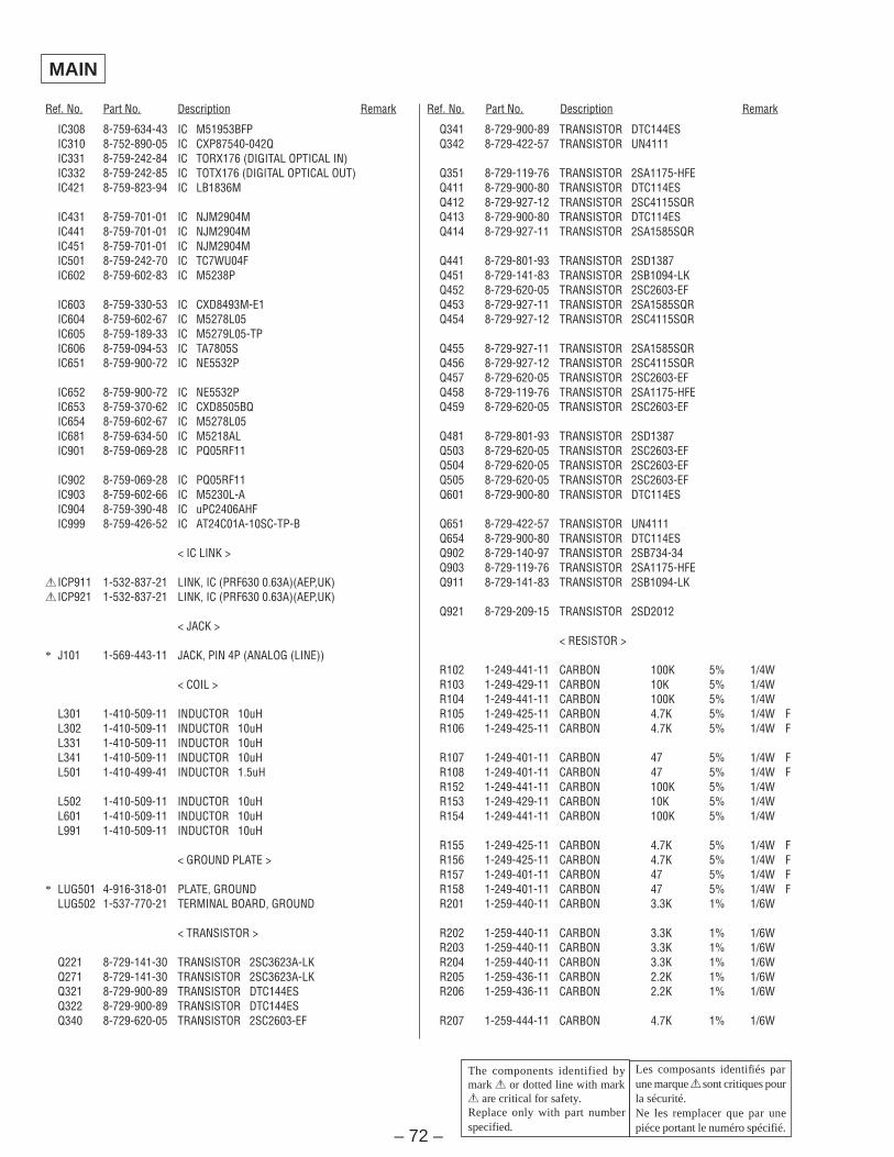
Ref. No. Part No. Description Remark Ref. No. Part No. Description Remark
IC308 8-759-634-43 IC M51953BFPIC310 8-752-890-05 IC CXP87540-042QIC331 8-759-242-84 IC TORX176 (DIGITAL OPTICAL IN)IC332 8-759-242-85 IC TOTX176 (DIGITAL OPTICAL OUT)IC421 8-759-823-94 IC LB1836M
IC431 8-759-701-01 IC NJM2904MIC441 8-759-701-01 IC NJM2904MIC451 8-759-701-01 IC NJM2904MIC501 8-759-242-70 IC TC7WU04FIC602 8-759-602-83 IC M5238P
IC603 8-759-330-53 IC CXD8493M-E1IC604 8-759-602-67 IC M5278L05IC605 8-759-189-33 IC M5279L05-TPIC606 8-759-094-53 IC TA7805SIC651 8-759-900-72 IC NE5532P
IC652 8-759-900-72 IC NE5532PIC653 8-759-370-62 IC CXD8505BQIC654 8-759-602-67 IC M5278L05IC681 8-759-634-50 IC M5218ALIC901 8-759-069-28 IC PQ05RF11
IC902 8-759-069-28 IC PQ05RF11IC903 8-759-602-66 IC M5230L-AIC904 8-759-390-48 IC uPC2406AHFIC999 8-759-426-52 IC AT24C01A-10SC-TP-B
< IC LINK >
! ICP911 1-532-837-21 LINK, IC (PRF630 0.63A)(AEP,UK)! ICP921 1-532-837-21 LINK, IC (PRF630 0.63A)(AEP,UK)
< JACK >
* J101 1-569-443-11 JACK, PIN 4P (ANALOG (LINE))
< COIL >
L301 1-410-509-11 INDUCTOR 10uHL302 1-410-509-11 INDUCTOR 10uHL331 1-410-509-11 INDUCTOR 10uHL341 1-410-509-11 INDUCTOR 10uHL501 1-410-499-41 INDUCTOR 1.5uH
L502 1-410-509-11 INDUCTOR 10uHL601 1-410-509-11 INDUCTOR 10uHL991 1-410-509-11 INDUCTOR 10uH
< GROUND PLATE >
* LUG501 4-916-318-01 PLATE, GROUNDLUG502 1-537-770-21 TERMINAL BOARD, GROUND
< TRANSISTOR >
Q221 8-729-141-30 TRANSISTOR 2SC3623A-LKQ271 8-729-141-30 TRANSISTOR 2SC3623A-LKQ321 8-729-900-89 TRANSISTOR DTC144ESQ322 8-729-900-89 TRANSISTOR DTC144ESQ340 8-729-620-05 TRANSISTOR 2SC2603-EF
Q341 8-729-900-89 TRANSISTOR DTC144ESQ342 8-729-422-57 TRANSISTOR UN4111
Q351 8-729-119-76 TRANSISTOR 2SA1175-HFEQ411 8-729-900-80 TRANSISTOR DTC114ESQ412 8-729-927-12 TRANSISTOR 2SC4115SQRQ413 8-729-900-80 TRANSISTOR DTC114ESQ414 8-729-927-11 TRANSISTOR 2SA1585SQR
Q441 8-729-801-93 TRANSISTOR 2SD1387Q451 8-729-141-83 TRANSISTOR 2SB1094-LKQ452 8-729-620-05 TRANSISTOR 2SC2603-EFQ453 8-729-927-11 TRANSISTOR 2SA1585SQRQ454 8-729-927-12 TRANSISTOR 2SC4115SQR
Q455 8-729-927-11 TRANSISTOR 2SA1585SQRQ456 8-729-927-12 TRANSISTOR 2SC4115SQRQ457 8-729-620-05 TRANSISTOR 2SC2603-EFQ458 8-729-119-76 TRANSISTOR 2SA1175-HFEQ459 8-729-620-05 TRANSISTOR 2SC2603-EF
Q481 8-729-801-93 TRANSISTOR 2SD1387Q503 8-729-620-05 TRANSISTOR 2SC2603-EFQ504 8-729-620-05 TRANSISTOR 2SC2603-EFQ505 8-729-620-05 TRANSISTOR 2SC2603-EFQ601 8-729-900-80 TRANSISTOR DTC114ES
Q651 8-729-422-57 TRANSISTOR UN4111Q654 8-729-900-80 TRANSISTOR DTC114ESQ902 8-729-140-97 TRANSISTOR 2SB734-34Q903 8-729-119-76 TRANSISTOR 2SA1175-HFEQ911 8-729-141-83 TRANSISTOR 2SB1094-LK
Q921 8-729-209-15 TRANSISTOR 2SD2012
< RESISTOR >
R102 1-249-441-11 CARBON 100K 5% 1/4WR103 1-249-429-11 CARBON 10K 5% 1/4WR104 1-249-441-11 CARBON 100K 5% 1/4WR105 1-249-425-11 CARBON 4.7K 5% 1/4W FR106 1-249-425-11 CARBON 4.7K 5% 1/4W F
R107 1-249-401-11 CARBON 47 5% 1/4W FR108 1-249-401-11 CARBON 47 5% 1/4W FR152 1-249-441-11 CARBON 100K 5% 1/4WR153 1-249-429-11 CARBON 10K 5% 1/4WR154 1-249-441-11 CARBON 100K 5% 1/4W
R155 1-249-425-11 CARBON 4.7K 5% 1/4W FR156 1-249-425-11 CARBON 4.7K 5% 1/4W FR157 1-249-401-11 CARBON 47 5% 1/4W FR158 1-249-401-11 CARBON 47 5% 1/4W FR201 1-259-440-11 CARBON 3.3K 1% 1/6W
R202 1-259-440-11 CARBON 3.3K 1% 1/6WR203 1-259-440-11 CARBON 3.3K 1% 1/6WR204 1-259-440-11 CARBON 3.3K 1% 1/6WR205 1-259-436-11 CARBON 2.2K 1% 1/6WR206 1-259-436-11 CARBON 2.2K 1% 1/6W
R207 1-259-444-11 CARBON 4.7K 1% 1/6W
MAIN
Les composants identifiés parune marque ! sont critiques pourla sécurité.Ne les remplacer que par unepiéce portant le numéro spécifié.
The components identified bymark ! or dotted line with mark! are critical for safety.Replace only with part numberspecified.
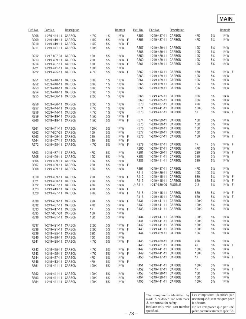
– 73 –
Ref. No. Part No. Description Remark Ref. No. Part No. Description Remark
R208 1-259-444-11 CARBON 4.7K 1% 1/6WR209 1-249-419-11 CARBON 1.5K 5% 1/4W FR210 1-249-419-11 CARBON 1.5K 5% 1/4W FR211 1-249-441-11 CARBON 100K 5% 1/4W
R212 1-247-807-31 CARBON 100 5% 1/4WR213 1-249-409-11 CARBON 220 5% 1/4W FR214 1-249-407-11 CARBON 150 5% 1/4W FR221 1-249-441-11 CARBON 100K 5% 1/4WR222 1-249-425-11 CARBON 4.7K 5% 1/4W F
R251 1-259-440-11 CARBON 3.3K 1% 1/6WR252 1-259-440-11 CARBON 3.3K 1% 1/6WR253 1-259-440-11 CARBON 3.3K 1% 1/6WR254 1-259-440-11 CARBON 3.3K 1% 1/6WR255 1-259-436-11 CARBON 2.2K 1% 1/6W
R256 1-259-436-11 CARBON 2.2K 1% 1/6WR257 1-259-444-11 CARBON 4.7K 1% 1/6WR258 1-259-444-11 CARBON 4.7K 1% 1/6WR259 1-249-419-11 CARBON 1.5K 5% 1/4W FR260 1-249-419-11 CARBON 1.5K 5% 1/4W F
R261 1-249-441-11 CARBON 100K 5% 1/4WR262 1-247-807-31 CARBON 100 5% 1/4WR263 1-249-409-11 CARBON 220 5% 1/4W FR264 1-249-407-11 CARBON 150 5% 1/4W FR272 1-249-425-11 CARBON 4.7K 5% 1/4W F
R303 1-249-437-11 CARBON 47K 5% 1/4WR305 1-249-429-11 CARBON 10K 5% 1/4WR306 1-249-429-11 CARBON 10K 5% 1/4WR307 1-249-409-11 CARBON 220 5% 1/4W FR308 1-249-429-11 CARBON 10K 5% 1/4W
R310 1-249-409-11 CARBON 220 5% 1/4W FR321 1-249-433-11 CARBON 22K 5% 1/4WR322 1-249-437-11 CARBON 47K 5% 1/4WR323 1-249-413-11 CARBON 470 5% 1/4W FR329 1-249-427-11 CARBON 6.8K 5% 1/4W F
R330 1-249-409-11 CARBON 220 5% 1/4W FR332 1-249-437-11 CARBON 47K 5% 1/4WR333 1-249-417-11 CARBON 1K 5% 1/4W FR335 1-247-807-31 CARBON 100 5% 1/4WR336 1-249-431-11 CARBON 15K 5% 1/4W
R337 1-249-421-11 CARBON 2.2K 5% 1/4W FR338 1-249-421-11 CARBON 2.2K 5% 1/4W FR339 1-249-435-11 CARBON 33K 5% 1/4WR340 1-249-429-11 CARBON 10K 5% 1/4WR341 1-249-425-11 CARBON 4.7K 5% 1/4W F
R342 1-249-425-11 CARBON 4.7K 5% 1/4W FR343 1-249-425-11 CARBON 4.7K 5% 1/4W FR344 1-249-437-11 CARBON 47K 5% 1/4WR345 1-249-413-11 CARBON 470 5% 1/4W FR351 1-249-441-11 CARBON 100K 5% 1/4W
R352 1-249-441-11 CARBON 100K 5% 1/4WR353 1-249-441-11 CARBON 100K 5% 1/4WR354 1-249-441-11 CARBON 100K 5% 1/4W
R355 1-249-437-11 CARBON 47K 5% 1/4WR356 1-249-437-11 CARBON 47K 5% 1/4W
R357 1-249-429-11 CARBON 10K 5% 1/4WR358 1-249-429-11 CARBON 10K 5% 1/4WR359 1-249-429-11 CARBON 10K 5% 1/4WR360 1-249-429-11 CARBON 10K 5% 1/4WR361 1-249-429-11 CARBON 10K 5% 1/4W
R362 1-249-413-11 CARBON 470 5% 1/4W FR363 1-249-429-11 CARBON 10K 5% 1/4WR364 1-249-429-11 CARBON 10K 5% 1/4WR365 1-249-429-11 CARBON 10K 5% 1/4WR366 1-249-429-11 CARBON 10K 5% 1/4W
R368 1-249-435-11 CARBON 33K 5% 1/4WR369 1-249-435-11 CARBON 33K 5% 1/4WR370 1-249-437-11 CARBON 47K 5% 1/4WR371 1-249-441-11 CARBON 100K 5% 1/4WR373 1-249-417-11 CARBON 1K 5% 1/4W F
R374 1-249-429-11 CARBON 10K 5% 1/4WR375 1-249-429-11 CARBON 10K 5% 1/4WR376 1-249-429-11 CARBON 10K 5% 1/4WR377 1-249-429-11 CARBON 10K 5% 1/4WR378 1-249-407-11 CARBON 150 5% 1/4W F
R379 1-249-417-11 CARBON 1K 5% 1/4W FR380 1-249-437-11 CARBON 47K 5% 1/4WR381 1-249-409-11 CARBON 220 5% 1/4W FR382 1-249-411-11 CARBON 330 5% 1/4WR383 1-249-411-11 CARBON 330 5% 1/4W
R391 1-249-437-11 CARBON 47K 5% 1/4WR411 1-249-429-11 CARBON 10K 5% 1/4WR412 1-249-415-11 CARBON 680 5% 1/4W FR413 1-249-415-11 CARBON 680 5% 1/4W F!R414 1-217-639-00 FUSIBLE 2.2 5% 1/4W F
R415 1-249-415-11 CARBON 680 5% 1/4W FR416 1-249-415-11 CARBON 680 5% 1/4W FR431 1-249-441-11 CARBON 100K 5% 1/4WR432 1-249-441-11 CARBON 100K 5% 1/4WR433 1-249-441-11 CARBON 100K 5% 1/4W
R434 1-249-441-11 CARBON 100K 5% 1/4WR441 1-249-441-11 CARBON 100K 5% 1/4WR442 1-249-441-11 CARBON 100K 5% 1/4WR443 1-249-441-11 CARBON 100K 5% 1/4WR444 1-249-429-11 CARBON 10K 5% 1/4W
R445 1-249-433-11 CARBON 22K 5% 1/4WR446 1-249-401-11 CARBON 47 5% 1/4W FR447 1-249-441-11 CARBON 100K 5% 1/4WR449 1-249-441-11 CARBON 100K 5% 1/4WR450 1-249-417-11 CARBON 1K 5% 1/4W F
R451 1-249-441-11 CARBON 100K 5% 1/4WR452 1-249-417-11 CARBON 1K 5% 1/4W FR453 1-249-429-11 CARBON 10K 5% 1/4WR454 1-249-429-11 CARBON 10K 5% 1/4WR455 1-249-441-11 CARBON 100K 5% 1/4W
Les composants identifiés parune marque ! sont critiques pourla sécurité.Ne les remplacer que par unepiéce portant le numéro spécifié.
The components identified bymark ! or dotted line with mark! are critical for safety.Replace only with part numberspecified.
MAIN
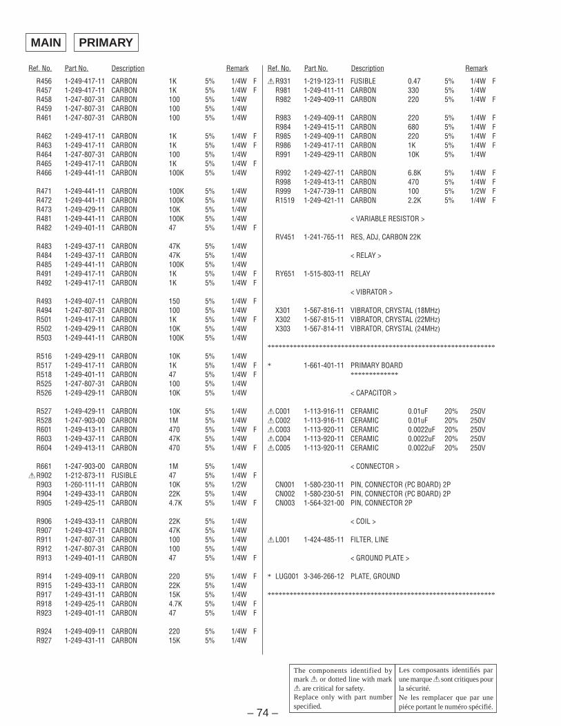
– 74 –
Ref. No. Part No. Description Remark Ref. No. Part No. Description Remark
R456 1-249-417-11 CARBON 1K 5% 1/4W FR457 1-249-417-11 CARBON 1K 5% 1/4W FR458 1-247-807-31 CARBON 100 5% 1/4WR459 1-247-807-31 CARBON 100 5% 1/4WR461 1-247-807-31 CARBON 100 5% 1/4W
R462 1-249-417-11 CARBON 1K 5% 1/4W FR463 1-249-417-11 CARBON 1K 5% 1/4W FR464 1-247-807-31 CARBON 100 5% 1/4WR465 1-249-417-11 CARBON 1K 5% 1/4W FR466 1-249-441-11 CARBON 100K 5% 1/4W
R471 1-249-441-11 CARBON 100K 5% 1/4WR472 1-249-441-11 CARBON 100K 5% 1/4WR473 1-249-429-11 CARBON 10K 5% 1/4WR481 1-249-441-11 CARBON 100K 5% 1/4WR482 1-249-401-11 CARBON 47 5% 1/4W F
R483 1-249-437-11 CARBON 47K 5% 1/4WR484 1-249-437-11 CARBON 47K 5% 1/4WR485 1-249-441-11 CARBON 100K 5% 1/4WR491 1-249-417-11 CARBON 1K 5% 1/4W FR492 1-249-417-11 CARBON 1K 5% 1/4W F
R493 1-249-407-11 CARBON 150 5% 1/4W FR494 1-247-807-31 CARBON 100 5% 1/4WR501 1-249-417-11 CARBON 1K 5% 1/4W FR502 1-249-429-11 CARBON 10K 5% 1/4WR503 1-249-441-11 CARBON 100K 5% 1/4W
R516 1-249-429-11 CARBON 10K 5% 1/4WR517 1-249-417-11 CARBON 1K 5% 1/4W FR518 1-249-401-11 CARBON 47 5% 1/4W FR525 1-247-807-31 CARBON 100 5% 1/4WR526 1-249-429-11 CARBON 10K 5% 1/4W
R527 1-249-429-11 CARBON 10K 5% 1/4WR528 1-247-903-00 CARBON 1M 5% 1/4WR601 1-249-413-11 CARBON 470 5% 1/4W FR603 1-249-437-11 CARBON 47K 5% 1/4WR604 1-249-413-11 CARBON 470 5% 1/4W F
R661 1-247-903-00 CARBON 1M 5% 1/4W!R902 1-212-873-11 FUSIBLE 47 5% 1/4W F
R903 1-260-111-11 CARBON 10K 5% 1/2WR904 1-249-433-11 CARBON 22K 5% 1/4WR905 1-249-425-11 CARBON 4.7K 5% 1/4W F
R906 1-249-433-11 CARBON 22K 5% 1/4WR907 1-249-437-11 CARBON 47K 5% 1/4WR911 1-247-807-31 CARBON 100 5% 1/4WR912 1-247-807-31 CARBON 100 5% 1/4WR913 1-249-401-11 CARBON 47 5% 1/4W F
R914 1-249-409-11 CARBON 220 5% 1/4W FR915 1-249-433-11 CARBON 22K 5% 1/4WR917 1-249-431-11 CARBON 15K 5% 1/4WR918 1-249-425-11 CARBON 4.7K 5% 1/4W FR923 1-249-401-11 CARBON 47 5% 1/4W F
R924 1-249-409-11 CARBON 220 5% 1/4W FR927 1-249-431-11 CARBON 15K 5% 1/4W
!R931 1-219-123-11 FUSIBLE 0.47 5% 1/4W FR981 1-249-411-11 CARBON 330 5% 1/4WR982 1-249-409-11 CARBON 220 5% 1/4W F
R983 1-249-409-11 CARBON 220 5% 1/4W FR984 1-249-415-11 CARBON 680 5% 1/4W FR985 1-249-409-11 CARBON 220 5% 1/4W FR986 1-249-417-11 CARBON 1K 5% 1/4W FR991 1-249-429-11 CARBON 10K 5% 1/4W
R992 1-249-427-11 CARBON 6.8K 5% 1/4W FR998 1-249-413-11 CARBON 470 5% 1/4W FR999 1-247-739-11 CARBON 100 5% 1/2W FR1519 1-249-421-11 CARBON 2.2K 5% 1/4W F
< VARIABLE RESISTOR >
RV451 1-241-765-11 RES, ADJ, CARBON 22K
< RELAY >
RY651 1-515-803-11 RELAY
< VIBRATOR >
X301 1-567-816-11 VIBRATOR, CRYSTAL (18MHz)X302 1-567-815-11 VIBRATOR, CRYSTAL (22MHz)X303 1-567-814-11 VIBRATOR, CRYSTAL (24MHz)
**************************************************************
* 1-661-401-11 PRIMARY BOARD*************
< CAPACITOR >
!C001 1-113-916-11 CERAMIC 0.01uF 20% 250V!C002 1-113-916-11 CERAMIC 0.01uF 20% 250V!C003 1-113-920-11 CERAMIC 0.0022uF 20% 250V!C004 1-113-920-11 CERAMIC 0.0022uF 20% 250V!C005 1-113-920-11 CERAMIC 0.0022uF 20% 250V
< CONNECTOR >
CN001 1-580-230-11 PIN, CONNECTOR (PC BOARD) 2PCN002 1-580-230-51 PIN, CONNECTOR (PC BOARD) 2PCN003 1-564-321-00 PIN, CONNECTOR 2P
< COIL >
!L001 1-424-485-11 FILTER, LINE
< GROUND PLATE >
* LUG001 3-346-266-12 PLATE, GROUND
**************************************************************
PRIMARY
Les composants identifiés parune marque ! sont critiques pourla sécurité.Ne les remplacer que par unepiéce portant le numéro spécifié.
The components identified bymark ! or dotted line with mark! are critical for safety.Replace only with part numberspecified.
MAIN
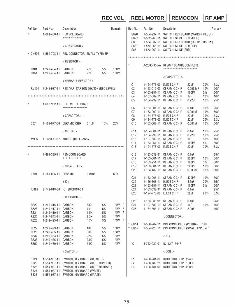
– 75 –
Ref. No. Part No. Description Remark Ref. No. Part No. Description Remark
* 1-661-400-11 REC VOL BOARD*************
< CONNECTOR >
* CN602 1-564-708-11 PIN, CONNECTOR (SMALL TYPE) 6P
< RESISTOR >
R101 1-249-434-11 CARBON 27K 5% 1/4WR151 1-249-434-11 CARBON 27K 5% 1/4W
< VARIABLE RESISTOR >
RV101 1-241-937-11 RES, VAR, CARBON 20K/20K (REC LEVEL)
**************************************************************
* 1-667-962-11 REEL MOTOR BOARD****************
< CAPACITOR >
C07 1-163-077-00 CERAMIC CHIP 0.1uF 10% 25V
< MOTOR >
M905 X-3363-110-2 MOTOR (REEL) ASSY
**************************************************************
* 1-661-399-11 REMOCON BOARD*************
< CAPACITOR >
C891 1-164-096-11 CERAMIC 0.01uF 50V
< IC >
IC891 8-742-018-00 IC SBX1810-59
< RESISTOR >
R822 1-249-415-11 CARBON 680 5% 1/4W FR823 1-249-417-11 CARBON 1K 5% 1/4W FR824 1-249-419-11 CARBON 1.5K 5% 1/4W FR825 1-247-843-11 CARBON 3.3K 5% 1/4WR826 1-249-425-11 CARBON 4.7K 5% 1/4W F
R827 1-249-429-11 CARBON 10K 5% 1/4WR828 1-249-435-11 CARBON 33K 5% 1/4WR837 1-249-433-11 CARBON 22K 5% 1/4WR838 1-249-435-11 CARBON 33K 5% 1/4WR852 1-249-439-11 CARBON 68K 5% 1/4W
< SWITCH >
S821 1-554-937-11 SWITCH, KEY BOARD (ID, AUTO)S822 1-554-937-11 SWITCH, KEY BOARD (ID, RENUNBER)S823 1-554-937-11 SWITCH, KEY BOARD (ID, REHEARSAL)S824 1-554-937-11 SWITCH, KEY BOARD (WRITE)S825 1-554-937-11 SWITCH, KEY BOARD (ERASE)
S826 1-554-937-11 SWITCH, KEY BOARD (MARGIN RESET)S827 1-572-268-11 SWITCH, SLIDE (REC MDOE)S831 1-554-937-11 SWITCH, KEY BOARD (OPEN/CLOSE 6)S837 1-572-268-11 SWITCH, SLIDE (ID MODE)S851 1-572-269-11 SWITCH, SLIDE (SBM)
**************************************************************
* A-2006-455-A RF AMP BOARD, COMPLETE**********************
< CAPACITOR >
C1 1-124-778-00 ELECT CHIP 22uF 20% 6.3VC2 1-163-019-00 CERAMIC CHIP 0.0068uF 10% 50VC3 1-163-251-11 CERAMIC CHIP 100PF 5% 50VC4 1-107-682-11 CERAMIC CHIP 1uF 10% 16VC5 1-164-299-11 CERAMIC CHIP 0.22uF 10% 25V
C6 1-164-004-11 CERAMIC CHIP 0.1uF 10% 25VC7 1-163-009-11 CERAMIC CHIP 0.001uF 10% 50VC8 1-124-778-00 ELECT CHIP 22uF 20% 6.3VC9 1-124-778-00 ELECT CHIP 22uF 20% 6.3VC10 1-163-009-11 CERAMIC CHIP 0.001uF 10% 50V
C11 1-164-004-11 CERAMIC CHIP 0.1uF 10% 25VC12 1-164-299-11 CERAMIC CHIP 0.22uF 10% 25VC13 1-107-682-11 CERAMIC CHIP 1uF 10% 16VC14 1-163-251-11 CERAMIC CHIP 100PF 5% 50VC15 1-124-778-00 ELECT CHIP 22uF 20% 6.3V
C16 1-163-038-91 CERAMIC CHIP 0.1uF 25VC17 1-163-001-11 CERAMIC CHIP 220PF 10% 50VC18 1-163-251-11 CERAMIC CHIP 100PF 5% 50VC19 1-163-001-11 CERAMIC CHIP 220PF 10% 50VC20 1-164-182-11 CERAMIC CHIP 0.0033uF 10% 50V
C21 1-163-005-11 CERAMIC CHIP 470PF 10% 50VC22 1-126-603-11 ELECT CHIP 4.7uF 20% 35VC23 1-163-251-11 CERAMIC CHIP 100PF 5% 50VC24 1-163-038-91 CERAMIC CHIP 0.1uF 25VC25 1-124-778-00 ELECT CHIP 22uF 20% 6.3V
C26 1-163-038-91 CERAMIC CHIP 0.1uF 25VC27 1-107-682-11 CERAMIC CHIP 1uF 10% 16VC28 1-164-505-11 CERAMIC CHIP 2.2uF 16V
< CONNECTOR >
* CN51 1-566-207-11 PIN, CONNECTOR (PC BOARD) 14P* CN52 1-564-720-11 PIN, CONNECTOR (SMALL TYPE) 4P
< IC >
IC1 8-752-039-01 IC CXA1364R
< COIL >
L1 1-408-781-00 INDUCTOR CHIP 22uHL2 1-408-789-21 INDUCTOR CHIP 100uHL3 1-408-781-00 INDUCTOR CHIP 22uH
REC VOL REEL MOTOR REMOCON RF AMP
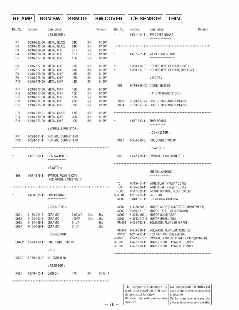
– 76 –
Ref. No. Part No. Description Remark Ref. No. Part No. Description Remark
< RESISTOR >
R1 1-216-082-00 METAL GLAZE 24K 5% 1/10WR2 1-216-082-00 METAL GLAZE 24K 5% 1/10WR3 1-216-066-00 METAL CHIP 5.1K 5% 1/10WR4 1-216-066-00 METAL CHIP 5.1K 5% 1/10WR5 1-216-077-00 METAL CHIP 15K 5% 1/10W
R6 1-216-077-00 METAL CHIP 15K 5% 1/10WR7 1-216-077-00 METAL CHIP 15K 5% 1/10WR8 1-216-079-00 METAL CHIP 18K 5% 1/10WR9 1-216-075-00 METAL CHIP 12K 5% 1/10WR10 1-216-079-00 METAL CHIP 18K 5% 1/10W
R11 1-216-077-00 METAL CHIP 15K 5% 1/10WR12 1-216-077-00 METAL CHIP 15K 5% 1/10WR13 1-216-077-00 METAL CHIP 15K 5% 1/10WR14 1-216-081-00 METAL CHIP 22K 5% 1/10WR15 1-216-085-00 METAL CHIP 33K 5% 1/10W
R16 1-216-089-91 METAL GLAZE 47K 5% 1/10WR17 1-216-080-00 METAL CHIP 20K 5% 1/10WR18 1-216-073-00 METAL CHIP 10K 5% 1/10W
< VARIABLE RESISTOR >
RV1 1-238-181-11 RES, ADJ, CERMET 4.7KRV2 1-238-181-11 RES, ADJ, CERMET 4.7K
**************************************************************
* 1-667-960-11 RGN SW BOARD************
< SWITCH >
S01 1-571-878-11 SWITCH, PUSH (2 KEY)(REC PROOF, CASSETTE IN)
**************************************************************
* 1-656-335-11 SBM DF BOARD************
< CAPACITOR >
C631 1-162-294-31 CERAMIC 0.001uF 10% 50VC632 1-162-282-31 CERAMIC 100PF 10% 50VC633 1-164-159-11 CERAMIC 0.1uF 50VC634 1-164-159-11 CERAMIC 0.1uF 50V
< CONNECTOR >
CN692 1-573-109-11 PIN, CONNECTOR 15P
< IC >
IC607 8-759-196-21 IC CXD8482Q
< RESISTOR >
R631 1-249-413-11 CARBON 470 5% 1/4W F
**************************************************************
* 1-661-404-11 SW COVER BOARD**************
**************************************************************
* 1-667-961-11 T/E SENSOR BOARD****************
* 3-368-456-01 HOLDER (END SENSOR LIGHT)* 3-368-457-01 HOLDER (END SENSOR) (RECEIVE)
< DIODE >
D01 8-719-988-42 DIODE GL453S
< PHOTO TRANSISTOR >
PH03 8-729-907-25 PHOTO TRANSISTOR PT4850FPH04 8-729-907-25 PHOTO TRANSISTOR PT4850F
**************************************************************
* 1-667-963-11 THIN BOARD**********
< CONNECTOR >
* CN21 1-564-336-61 PIN, CONNECTOR 2P
< SWITCH >
S02 1-572-458-11 SWITCH, PUSH (THIN DET)
**************************************************************
MISCELLANEOUS*************
70 1-775-464-11 WIRE (FLAT TYPE)(17 CORE)106 1-775-389-11 WIRE (FLAT TYPE)(31 CORE)FL801 1-517-382-11 INDICATOR TUBE, FLUORESCENT! IL001 1-251-234-11 INLET, AC
M900 8-848-567-11 DRUM ASSY DOU-03A
M901 X-3370-655-1 MOTOR ASSY (CASSETTE COMPARTMENT)M902 8-835-361-01 MOTOR, DC U-17B (CAPSTAN)M903 X-3363-109-1 MOTOR (CAM) ASSYM905 X-3363-110-2 MOTOR (REEL) ASSYPM903 1-454-732-11 SOLENOID, PLUNGER (BRAKE)
PM904 1-454-536-11 SOLENOID, PLUNGER (TENSION)RV101 1-241-937-11 RES, VAR, CARBON 20K/20K!S001 1-572-267-51 SWITCH, PUSH (AC POWER)(1 KEY)(POWER)!T901 1-427-889-11 TRANSFORMER, POWER (US,CND)!T901 1-427-890-11 TRANSFORMER, POWER (AEP,UK)
**************************************************************
Les composants identifiés parune marque ! sont critiques pourla sécurité.Ne les remplacer que par unepiéce portant le numéro spécifié.
The components identified bymark ! or dotted line with mark! are critical for safety.Replace only with part numberspecified.
THINT/E SENSORSW COVERSBM DFRGN SWRF AMP
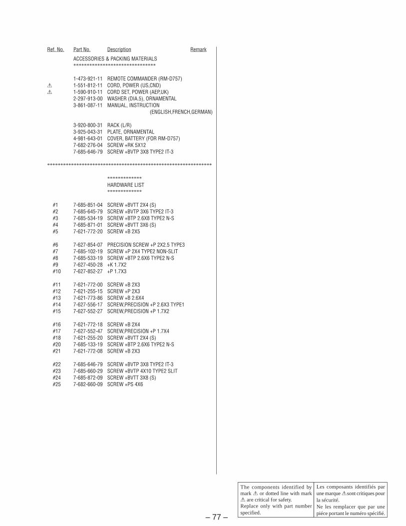
– 77 –
Ref. No. Part No. Description Remark
ACCESSORIES & PACKING MATERIALS*******************************
1-473-921-11 REMOTE COMMANDER (RM-D757)! 1-551-812-11 CORD, POWER (US,CND)! 1-590-910-11 CORD SET, POWER (AEP,UK)
2-297-913-00 WASHER (DIA.5), ORNAMENTAL3-861-087-11 MANUAL, INSTRUCTION
(ENGLISH,FRENCH,GERMAN)
3-920-800-31 RACK (L/R)3-925-043-31 PLATE, ORNAMENTAL4-981-643-01 COVER, BATTERY (FOR RM-D757)7-682-276-04 SCREW +RK 5X127-685-646-79 SCREW +BVTP 3X8 TYPE2 IT-3
**************************************************************
*************HARDWARE LIST*************
#1 7-685-851-04 SCREW +BVTT 2X4 (S)#2 7-685-645-79 SCREW +BVTP 3X6 TYPE2 IT-3#3 7-685-534-19 SCREW +BTP 2.6X8 TYPE2 N-S#4 7-685-871-01 SCREW +BVTT 3X6 (S)#5 7-621-772-20 SCREW +B 2X5
#6 7-627-854-07 PRECISION SCREW +P 2X2.5 TYPE3#7 7-685-102-19 SCREW +P 2X4 TYPE2 NON-SLIT#8 7-685-533-19 SCREW +BTP 2.6X6 TYPE2 N-S#9 7-627-450-28 +K 1.7X2#10 7-627-852-27 +P 1.7X3
#11 7-621-772-00 SCREW +B 2X3#12 7-621-255-15 SCREW +P 2X3#13 7-621-773-86 SCREW +B 2.6X4#14 7-627-556-17 SCREW,PRECISION +P 2.6X3 TYPE1#15 7-627-552-27 SCREW,PRECISION +P 1.7X2
#16 7-621-772-18 SCREW +B 2X4#17 7-627-552-47 SCREW,PRECISION +P 1.7X4#18 7-621-255-20 SCREW +BVTT 2X4 (S)#20 7-685-133-19 SCREW +BTP 2.6X6 TYPE2 N-S#21 7-621-772-08 SCREW +B 2X3
#22 7-685-646-79 SCREW +BVTP 3X8 TYPE2 IT-3#23 7-685-660-29 SCREW +BVTP 4X10 TYPE2 SLIT#24 7-685-872-09 SCREW +BVTT 3X8 (S)#25 7-682-660-09 SCREW +PS 4X6
Les composants identifiés parune marque ! sont critiques pourla sécurité.Ne les remplacer que par unepiéce portant le numéro spécifié.
The components identified bymark ! or dotted line with mark! are critical for safety.Replace only with part numberspecified.
Ver 1.2 2001.05Ver 1.2 2001.05Ver 1.2 2001.05Ver 1.2 2001.05Ver 1.2 2001.05
PCM-R300
REVISION HISTORY
Clicking the version allows you to jump to the revised page.Also, clicking the version at the upper right on the revised page allows you to jump to the next revisedpage.
Ver. Date Description of Revision
1.1 2001.06 Correction of electrical parts list (IC301).
1.0 1997.10 New
(SPM-01011)