PC to Radio Audio and Key-line Interface - Thethestrategyzone.com/interfacedoc.pdf · PC to Radio...
12
PC to Radio Audio and Key-line Interface Background - This simple interface was developed to capacitive couple audio signals between a radio and PC, to provide a means of adjusting audio levels between a radio and PC and to provide a key-line signal from the PC to a radio. The PC digital software FLDigi was used with the interface but other software could probably be used. Functional Description On the transmit side, the PC audio output has a very wide level range and can easily overdrive a radio modulator. The adjustment in the interface box is used to provide a finer adjustment for a given level on the PC Sound GUI. Once the potentiometer is adjusted and the PC sound level is set correctly, it should be easy to obtain the proper operating levels consistently just by verifying the PC GUI Level. The transmit audio signal comes from the PC’s 1/8” stereo speaker GREEN output connector (TIP) and connects to the radio’s 6 pin mini-din digital connector on pin 1 – Data In. The second channel (Ring) of the stereo jack was terminated with a resistor on the board but could be used with a speaker if desired. On the receive side, the demodulator has a fixed level output. Once initially set, the level from the radio to the PC can be within specification and the software GUI can be used for operational adjustments. The receive audio signal comes from the PC’s 1/8” stereo speaker PINK output connector and connects to the radio’s 6 pin mini-din digital connector on pin 5 – Data Out. FLdigi uses the RS232 signals DTR or RTS to control the key-line, PTT, transmit enable signal. The interface is designed to use the signal DTR (pin 4) to drive the relay. When DTR is asserted, the relay contacts close and the radio is in transmit mode. RTS could be used instead of DTR by moving the connection within the DB9 connector and configured in the software. The initial design used a 12v, 1200 ohm coil reed relay, which only requires 10mA of current. Subsequent units were built using a 5v, 500 ohm reed relay, which required a 10k ohm potentiometer in series to adjust the potential 12v RS232 level down to the 5v coil voltage for the relay. The 6 pin mini-din pins 2 and 3 (Pin 2 – Gnd and Pin 3 –PTT) are connected by the relay to put the radio into transmit mode.
Transcript of PC to Radio Audio and Key-line Interface - Thethestrategyzone.com/interfacedoc.pdf · PC to Radio...
PC to Radio Audio and Key-line Interface
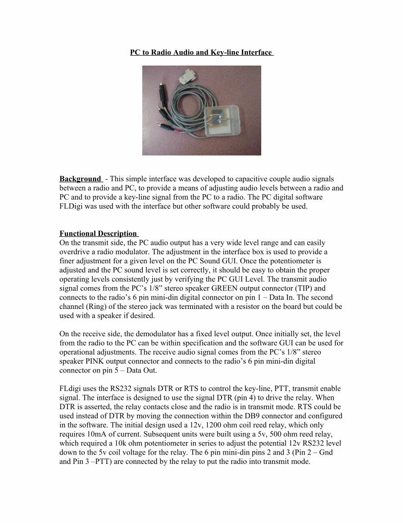
Background - This simple interface was developed to capacitive couple audio signals between a radio and PC, to provide a means of adjusting audio levels between a radio and PC and to provide a key-line signal from the PC to a radio. The PC digital software FLDigi was used with the interface but other software could probably be used.
Functional Description On the transmit side, the PC audio output has a very wide level range and can easily overdrive a radio modulator. The adjustment in the interface box is used to provide a finer adjustment for a given level on the PC Sound GUI. Once the potentiometer is adjusted and the PC sound level is set correctly, it should be easy to obtain the proper operating levels consistently just by verifying the PC GUI Level. The transmit audio signal comes from the PC’s 1/8” stereo speaker GREEN output connector (TIP) and connects to the radio’s 6 pin mini-din digital connector on pin 1 – Data In. The second channel (Ring) of the stereo jack was terminated with a resistor on the board but could be used with a speaker if desired. On the receive side, the demodulator has a fixed level output. Once initially set, the level from the radio to the PC can be within specification and the software GUI can be used for operational adjustments. The receive audio signal comes from the PC’s 1/8” stereo speaker PINK output connector and connects to the radio’s 6 pin mini-din digital connector on pin 5 – Data Out. FLdigi uses the RS232 signals DTR or RTS to control the key-line, PTT, transmit enable signal. The interface is designed to use the signal DTR (pin 4) to drive the relay. When DTR is asserted, the relay contacts close and the radio is in transmit mode. RTS could be used instead of DTR by moving the connection within the DB9 connector and configured in the software. The initial design used a 12v, 1200 ohm coil reed relay, which only requires 10mA of current. Subsequent units were built using a 5v, 500 ohm reed relay, which required a 10k ohm potentiometer in series to adjust the potential 12v RS232 level down to the 5v coil voltage for the relay. The 6 pin mini-din pins 2 and 3 (Pin 2 – Gnd and Pin 3 –PTT) are connected by the relay to put the radio into transmit mode.
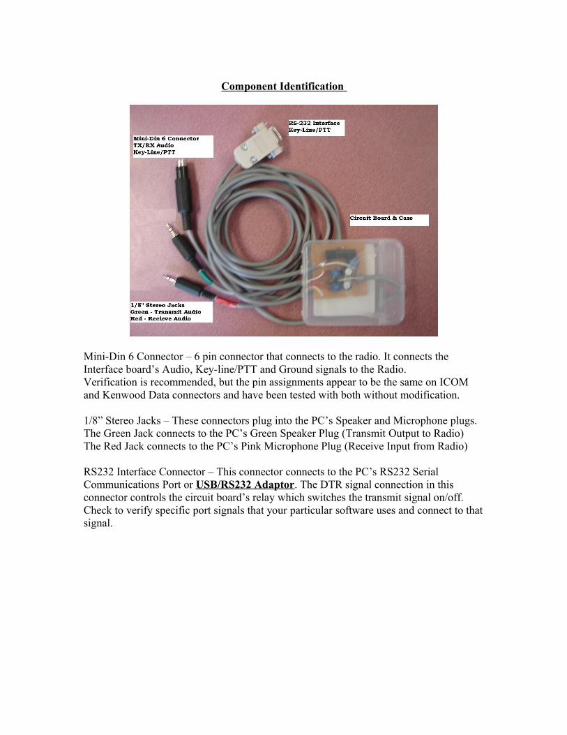
Component Identification
Mini-Din 6 Connector – 6 pin connector that connects to the radio. It connects the Interface board’s Audio, Key-line/PTT and Ground signals to the Radio. Verification is recommended, but the pin assignments appear to be the same on ICOM and Kenwood Data connectors and have been tested with both without modification.
1/8” Stereo Jacks – These connectors plug into the PC’s Speaker and Microphone plugs. The Green Jack connects to the PC’s Green Speaker Plug (Transmit Output to Radio)The Red Jack connects to the PC’s Pink Microphone Plug (Receive Input from Radio)
RS232 Interface Connector – This connector connects to the PC’s RS232 Serial Communications Port or USB/RS232 Adaptor. The DTR signal connection in this connector controls the circuit board’s relay which switches the transmit signal on/off.Check to verify specific port signals that your particular software uses and connect to that signal.

Adjustment Provisions
Relay Voltage Adjustment – RS232 signals have a voltage swing from -12 volts through 0 volts and onto +12 volts. The diode in series with the relay prevents a reverse bias to activate the coil so only one polarity will activate the coil. Some of the USB/RS232 converters may provide some voltage levels between a +5/-5 volt level to the +12/-12 volt level. The Relay Voltage Adjustment Potentiometer allows for a relay with a 5 volt coil to be used with whatever level above 5v happens to be available from the RS232 port.
Procedure:You will need a volt-ohm meter to complete the following procedureMeasure the coil resistance across the relay coil – Record Value
- The coil resistance should be such that only 10 mA of current is needed to activate the coil. i.e. 5 volt relay should have about 500Ω of resistance 5V/ 500Ω = 0.10 mA
Measure the Port signal’s voltage – Record Value - with a meter measure from pin 4 (DTR) to pin 5 (GND)
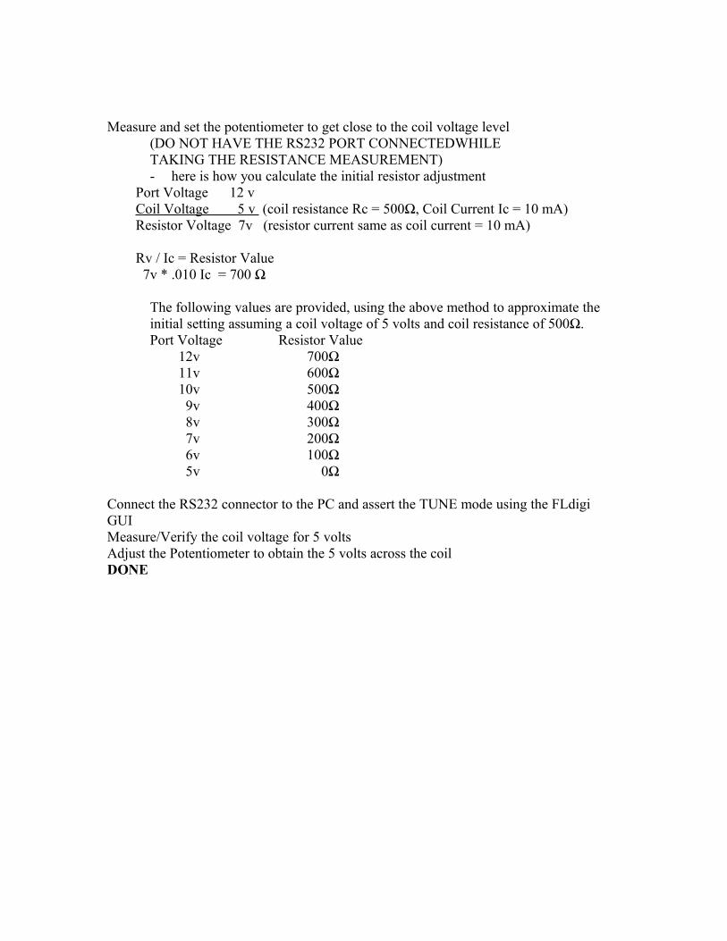
Measure and set the potentiometer to get close to the coil voltage level (DO NOT HAVE THE RS232 PORT CONNECTEDWHILE
TAKING THE RESISTANCE MEASUREMENT)- here is how you calculate the initial resistor adjustment
Port Voltage 12 v Coil Voltage 5 v (coil resistance Rc = 500Ω, Coil Current Ic = 10 mA) Resistor Voltage 7v (resistor current same as coil current = 10 mA) Rv / Ic = Resistor Value 7v * .010 Ic = 700 Ω
The following values are provided, using the above method to approximate the initial setting assuming a coil voltage of 5 volts and coil resistance of 500Ω.Port Voltage Resistor Value
12v 700Ω11v 600Ω10v 500Ω 9v 400Ω 8v 300Ω 7v 200Ω 6v 100Ω 5v 0Ω
Connect the RS232 connector to the PC and assert the TUNE mode using the FLdigi GUI Measure/Verify the coil voltage for 5 volts Adjust the Potentiometer to obtain the 5 volts across the coil DONE

Software Configuration to enable DTR control of the Transmit LineBelow is an image of the FLDigi configuration screen for hardware Control of the Radio’s Push to Talk or Transmit line
COM4 was configured because a USB-RS232 converter was used in this example although other RS232 Comm ports can be used
To install and configure the USB/RS232 adaptor to function with FLDigi,1. Connect the adaptor to the pc 2. Install the driver (if driver was already installed just go to Step 3) 3. To verify which serial port the adaptor is assigned
1. Go to Start 2. select Control Panel 3. Select System 4. Select Hardware5. Select Device Manager6. Select "Ports(COM & LPT)"7. Find the Adaptor's Manufacturers Name
In this case it is Edgeport. In Parenthesis the defined serial port is indicated (COMx)In this case (COM4)
8. Select this device9. select "Port Settings" Tab 10. Verify that "Flow Control is set to "HARDWARE"
If it is set to "NONE", Select the pull down and select
"HARDWARE" (Hardware will activate the DTR & RTS handshake signals that will be used by FLdigi)
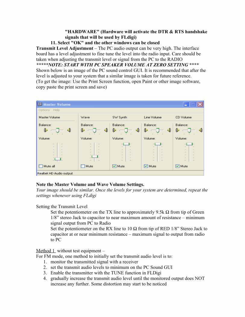
11. Select "OK" and the other windows can be closedTransmit Level Adjustment – The PC audio output can be very high. The interface board has a level adjustment to fine tune the level into the radio input. Care should be taken when adjusting the transmit level or signal from the PC to the RADIO *****NOTE: START WITH PC SPEAKER VOLUME AT ZERO SETTING **** Shown below is an image of the PC sound control GUI. It is recommended that after the level is adjusted to your system that a similar image is taken for future reference. (To get the image: Use the Print Screen function, open Paint or other image software, copy paste the print screen and save)
Note the Master Volume and Wave Volume Settings.Your image should be similar. Once the levels for your system are determined, repeat the settings whenever using FLdigi
Setting the Transmit Level Set the potentiometer on the TX line to approximately 9.5k Ω from tip of Green 1/8” stereo Jack to capacitor to near maximum amount of resistance – minimum signal output from PC to Radio Set the potentiometer on the RX line to 10 Ω from tip of RED 1/8” Stereo Jack to capacitor at or near minimum resistance – maximum signal to output from radio to PC
Method 1 without test equipment –For FM mode, one method to initially set the transmit audio level is to:
1. monitor the transmitted signal with a receiver2. set the transmit audio levels to minimum on the PC Sound GUI3. Enable the transmitter with the TUNE function in FLDigi 4. gradually increase the transmit audio level until the monitored output does NOT
increase any further. Some distortion may start to be noticed
5. Reduce the Output level until there is a slightly noticeable change in the level decreasing and no distortion
6. Some future fine adjustment might be needed
For ICOM IC706MKIIG users Recommended procedure w/o measurement device from ICOM IC706MKIIG manual Ch4 pg 37
- Enter CAL mode with TNC - If transciever data transmission fails or TX indicator is off or flashes decrease the input level until TX light is steady- If data is not transmitted and light is on steady - increase input level
Method 2 – Deviation Meter
Method 3 – Oscilloscope probesCheck your Radio’s Manual for the input level specifications Connect an Oscilloscope to the TX coupling capacitor and adjust per radio specification
ExampleThe input level specification, to a radio, that the PC output level needs to meet to properly drive the radio. Check your specific radio specification for the proper level.
Audio Input Level recommendation from 706MKIIG Manual 0.4 Vpk-pk (0.2 Vrms) Recommended Level 0.2 Vpk-pk (0.1 Vrms) to 0.5 Vpk-pk (0.25 Vrms)DO NOT EXCEED 0.6 Vpk-pk (0.3 Vrms) RIG WILL NOT BE ABLE TO MAINTAIN BW

Receive Level Adjustment – The radio’s audio from the data jack is at a fixed level. Check your radio manual for the output specification and compare to the PC’s input specification. The interface board has a potentiometer to assist adjusting any significant level differences if the level is too high coming from the radio. As a starting point, launch the FLdigi software and set the input level to “-20”. This initial setting is the midpoint of the input sensitivity range.
Overdriving the input to the PC will cause the waterfall view to turn RED. No signal will provide a black screen. If needed, adjust the board’s potentiometer for a light yellow waterfall with the squelch open and white noise/static is being received, this should allow for a finer adjustment using the GUI. Some adjustment might be needed to suit operating conditions and individual equipment set-up. An oscilloscope can be used to measure the audio level(s). Check your PC’s input level and Radio’s output level specifications.
Examples provided below:PC Audio Pink - Microphone Input
Impedence - 1k to 20k Ω Level - min 10mV (some older cards 100mV)
Radio Audio Icom 718 Audio Specifications (Accessory Socket/Data Port)AF out - Output Z = 4.7k Ω Output Level = 100 to 300mV rms
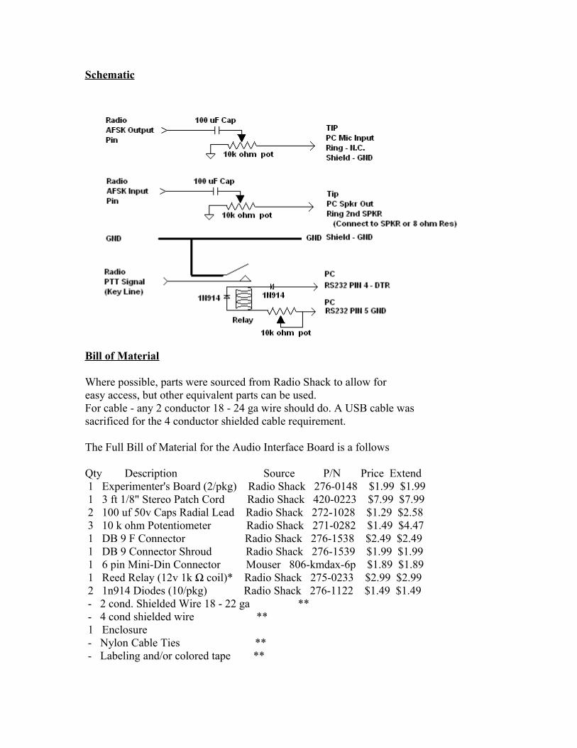
Schematic
Bill of Material
Where possible, parts were sourced from Radio Shack to allow for easy access, but other equivalent parts can be used.For cable - any 2 conductor 18 - 24 ga wire should do. A USB cable was sacrificed for the 4 conductor shielded cable requirement. The Full Bill of Material for the Audio Interface Board is a follows
Qty Description Source P/N Price Extend 1 Experimenter's Board (2/pkg) Radio Shack 276-0148 $1.99 $1.99 1 3 ft 1/8" Stereo Patch Cord Radio Shack 420-0223 $7.99 $7.99 2 100 uf 50v Caps Radial Lead Radio Shack 272-1028 $1.29 $2.58 3 10 k ohm Potentiometer Radio Shack 271-0282 $1.49 $4.47 1 DB 9 F Connector Radio Shack 276-1538 $2.49 $2.49 1 DB 9 Connector Shroud Radio Shack 276-1539 $1.99 $1.99 1 6 pin Mini-Din Connector Mouser 806-kmdax-6p $1.89 $1.89 1 Reed Relay (12v 1k Ω coil)* Radio Shack 275-0233 $2.99 $2.99 2 1n914 Diodes (10/pkg) Radio Shack 276-1122 $1.49 $1.49 - 2 cond. Shielded Wire 18 - 22 ga ** - 4 cond shielded wire ** 1 Enclosure - Nylon Cable Ties ** - Labeling and/or colored tape **
* Note: The relay on the BOM was used with success. A relay with a 5V/500 Ω coil might be better suited.
** Note: These parts can be generically sourced.
Alternates to the 1/8" Stereo Patch Cord
Qty (1) Stereo 1/8" Plugs(2/pack) Radio Shack 274-0248 $3.99(Cable will be needed to complete the Assembly)
For different length cables Qty (1) 6 ft 1/8" Stereo Patch Cord Radio Shack 420-2387 $8.99Qty (1) 1 ft 1/8" Stereo Patch Cord Radio Shack 420-2497 $5.99
Alternate for Capacitor Qty (2) 100 uf 50 V Caps Radial Lead Radio Shack 272-1044 $1.29
The enclosure pictured in the manual was a travel size cotton swab container for about $0.89 at the local pharmacy.
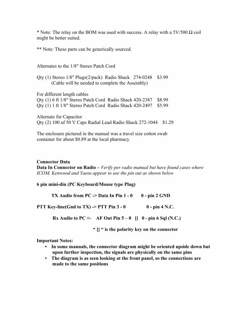
Connector DataData In Connector on Radio – Verify per radio manual but have found cases where ICOM, Kenwood and Yaesu appear to use the pin out as shown below
6 pin mini-din (PC Keyboard/Mouse type Plug)
TX Audio from PC -> Data In Pin 1 - 0 0 - pin 2 GND
PTT Key-line(Gnd to TX) -> PTT Pin 3 - 0 0 - pin 4 N.C.
Rx Audio to PC <- AF Out Pin 5 – 0 [] 0 - pin 6 Sql (N.C.)
“ [] “ is the polarity key on the connector
Important Notes:• In some manuals, the connector diagram might be oriented upside down but
upon further inspection, the signals are physically on the same pins • The diagram is as seen looking at the front panel, so the connections are
made to the same positions
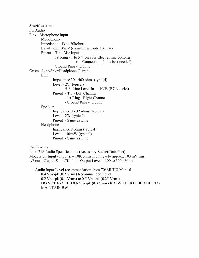
Specifications PC Audio Pink - Microphone Input
Monophonic Impedance - 1k to 20kohms Level - min 10mV (some older cards 100mV)Pinout - Tip - Mic Input
1st Ring - 1 to 5 V bias for Electret microphones (no Connection if bias isn't needed)
Ground Ring - GroundGreen - Line/Spkr/Headphone Output
LineImpedance 30 - 400 ohms (typical)Level - 2V (typical)
HiFi Line Level In = -10dB (RCA Jacks) Pinout - Tip - Left Channel
- 1st Ring - Right Channel - Ground Ring - Ground
SpeakerImpedance 8 - 32 ohms (typical)Level - 2W (typical) Pinout - Same as Line
HeadphoneImpedance 8 ohms (typical)Level - 100mW (typical) Pinout - Same as Line
Radio Audio Icom 718 Audio Specifications (Accessory Socket/Data Port)Modulator Input - Input Z = 10K ohms Input level= approx. 100 mV rmsAF out - Output Z = 4.7K ohms Output Level = 100 to 300mV rms
Audio Input Level recommendation from 706MKIIG Manual 0.4 Vpk-pk (0.2 Vrms) Recommended Level 0.2 Vpk-pk (0.1 Vrms) to 0.5 Vpk-pk (0.25 Vrms)DO NOT EXCEED 0.6 Vpk-pk (0.3 Vrms) RIG WILL NOT BE ABLE TO MAINTAIN BW

Conclusion
Four units were made in conjunction with the creation of this document. All four units are functional. The documentation should allow someone with electronic circuit building skill to duplicate the design. This design is a starting point and can be modified and certainly improved upon to suit a user’s specific design needs. If you are unsure about any aspects of the design, call on someone who is knowledgeable about electronics before any potential catastrophe occurs. Make sure that all adjustments and connections are made to meet all equipment specifications and FCC regulations.
Abbreviations &AcronymsΩ - Omega – Symbol for a unit of resistance AF - Audio Frequency AFSK – Audio Frequency Shift keying DTR – Data Transmit Ready GND – Ground GUI – Graphical User Interfacek –kilo or 1000kHz – kilohertz 1000 Hertz N.C. – No ConnectPC – Personal Computer PTT – Push To Talk RTS – Request To Send RX –Receive Spkr – Speaker TX – Transmit