PC BASED CONTROL OF ROBOTIC AND …engineering.nyu.edu/mechatronics/Control_Lab/Padmini/Nano/... ·...
34
1 PC BASED CONTROL OF ROBOTIC AND MECHATRONIC SYSTEMS UNDER MS-WINDOWS NT WORKSTATION Chunhao Joseph Lee 1 , and Constantinos Mavroidis 2 Robotics and Mechatronics Laboratory Department of Mechanical and Aerospace Engineering Rutgers University, The State University of New Jersey 98 Brett Rd., Piscataway, NJ 08854-8058 TEL: 732 - 445 - 0732, FAX: 732 - 445 3124 EMAIL: [email protected], WEBPAGE: http://cronos.rutgers.edu/~mavro ABSTRACT In this paper, a method is proposed to perform control using INTEL fi based Personal Com- puters operated by Windows NT ™ directly. The software package that was developed is called WinRec v.1 (Win dows Re al-time C ontrol). This low cost method keeps all the advantages of Win- dows NT without attaching any other kernels and avoids switching different operating systems between experimentation and control design/analysis. A thorough description of the method to set up the multimedia timer provided by Microsoft Development Network (MSDN) Library is pre- sented. Self-customized algorithms based on advanced control techniques can be implemented with the standard protocol that is established here. The proposed protocol is evaluated using two different systems in control experiments. In the first, an industrial robot manipulator is controlled by applying an independent joint PID control scheme. Results are also shown from experiments where LQR and H 2 controllers are applied to suppress vibrations of a flexible payload carried by the robot manipulator. In the second system, position, force, temperature, voltage and current data are simultaneously recorded in order to evaluate the performance of a Shape-Memory-Alloy (SMA) wire bundle actuator in open loop control experiments. INDEX TERMS: PC Based Control, Robotics, Digital Control. 1 Graduate Student, ASME and IEEE Student Member. Currently, Senior Research Engineer at General Motors, MI. 2 Assistant Professor, ASME and IEEE Member, Author for Correspondence.
Transcript of PC BASED CONTROL OF ROBOTIC AND …engineering.nyu.edu/mechatronics/Control_Lab/Padmini/Nano/... ·...

1
PC BASED CONTROL OF ROBOTIC AND MECHATRONIC SYSTEMS UNDER MS-WINDOWS NT WORKSTATION
Chunhao �Joseph� Lee1, and Constantinos Mavroidis2
Robotics and Mechatronics Laboratory Department of Mechanical and Aerospace Engineering Rutgers University, The State University of New Jersey
98 Brett Rd., Piscataway, NJ 08854-8058 TEL: 732 - 445 - 0732, FAX: 732 - 445 � 3124
EMAIL: [email protected], WEBPAGE: http://cronos.rutgers.edu/~mavro
ABSTRACT In this paper, a method is proposed to perform control using INTEL® based Personal Com-
puters operated by Windows NT� directly. The software package that was developed is called
WinRec v.1 (Windows Real-time Control). This low cost method keeps all the advantages of Win-
dows NT without attaching any other kernels and avoids switching different operating systems
between experimentation and control design/analysis. A thorough description of the method to set
up the multimedia timer provided by Microsoft Development Network (MSDN) Library is pre-
sented. Self-customized algorithms based on advanced control techniques can be implemented
with the standard protocol that is established here. The proposed protocol is evaluated using two
different systems in control experiments. In the first, an industrial robot manipulator is controlled
by applying an independent joint PID control scheme. Results are also shown from experiments
where LQR and H2 controllers are applied to suppress vibrations of a flexible payload carried by
the robot manipulator. In the second system, position, force, temperature, voltage and current data
are simultaneously recorded in order to evaluate the performance of a Shape-Memory-Alloy
(SMA) wire bundle actuator in open loop control experiments.
INDEX TERMS: PC Based Control, Robotics, Digital Control.
1 Graduate Student, ASME and IEEE Student Member. Currently, Senior Research Engineer at General Motors, MI. 2 Assistant Professor, ASME and IEEE Member, Author for Correspondence.
2
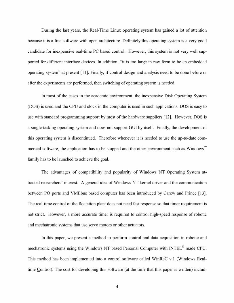
1 INTRODUCTION
Robotic and mechatronic systems are composed of many types of actuators, such as electri-
cal, pneumatic, hydraulic, or piezo-electric motors, and of different types of sensors, such as digital
encoders, potentiometers, tachometers, accelerometers, force sensors, or strain gauges. Control of
robotic and mechatronic systems requires reading data from all their sensors, calculating control
signals based on the sensor data, and then sending these control signals to the corresponding actua-
tors. The sensor data sampling rate and calculations must be very fast and highly accurate in order
to maintain the stability of the system. Performing such control and data acquisition tasks from
Personal Computers (PC) is very appealing because of their high-speed processing, low cost and
great popularity.
In this paper, a method is proposed to perform control and data acquisition with INTEL®
based Personal Computers (PC) under Windows NT� directly. The software package that was de-
veloped is called WinReC v.1 (Windows Real-time Control). There are two main reasons that
motivate the development of a PC based control software under Windows NT, such as WinReC
v.1. The first reason is that most of the current commercially available methods for PC based
control such as Programmable Logic Controllers (PLC) or commercially available Real-Time
Operating Systems are extremely expensive. The second reason is to avoid switching operating
systems between control experiments and control design/analysis. With WinReC v.1, control
analysis, design, data acquisition and experimental demonstration are performed on the same
platform which is Windows NT.
There are two main approaches in PC based control of electro-mechanical systems. The
first type is Programmable Logic Controller (PLC), which is added on the main platform and all
the data acquisition and calculations are performed on the on-board chips. One of the most popular

3
examples on the market is dSpace system [1], which is aimed for laboratory use as well as proto-
type implementation. The use of PLC reduces the programming efforts by researchers and
engineers, and the main platform is kept free to take charge of communications from either end-
users or other platforms such as a server [2]-[4]. The disadvantages of this feature are its high cost
and lack of flexibility. It is nontrivial to implement matrices required by Multi-Input-Multi-Output
(MIMO) systems or change the control parameters required by adaptive control systems. The
MIMO systems have to be transformed into transfer functions before being implemented [5]. The
parameters of adaptive control systems can not be updated by the PLC chip or under the PLC�s
timer. They can only be updated by the host computer with respect to the limit of the operating
system [6].
The second type of PC based control of electro-mechanical systems uses the CPU and
clock in the host computer to accomplish the data recording and calculations of the send-out sig-
nals needed to regulate the systems. It has been done under various operating systems. For
commercial or industrial purposes, there are Real-Time Operating Systems (RTOS), such as
QNX� from QNX Software Systems Ltd [7], LynxOS from Lynx Real-Time System Inc. and
VxWork� from WindRiver Systems [8]. There are also replacements of the Windows NT kernel
that allow the combination of features in Window's world with real time experimentation. Some
examples are Hyperkernel� from Imagination Systems Inc., Intime� from Radisys Corp and Tor-
nado� II from WindRiver Systems [9]. The advantages of such RTOS are their scalable run-time
software, high accuracy timers to tens or even hundreds of KHz and good support from the manu-
factures. The draw back of such systems is their high costs that may reach several tens of thousand
of dollars [10].
4
During the last years, the Real-Time Linux operating system has gained a lot of attention
because it is a free software with open architecture. Definitely this operating system is a very good
candidate for inexpensive real-time PC based control. However, this system is not very well sup-
ported for different interface devices. In addition, �it is too large in raw form to be an embedded
operating system� at present [11]. Finally, if control design and analysis need to be done before or
after the experiments are performed, then switching of operating system is needed.
In most of the cases in the academic environment, the inexpensive Disk Operating System
(DOS) is used and the CPU and clock in the computer is used in such applications. DOS is easy to
use with standard programming support by most of the hardware suppliers [12]. However, DOS is
a single-tasking operating system and does not support GUI by itself. Finally, the development of
this operating system is discontinued. Therefore whenever it is needed to use the up-to-date com-
mercial software, the application has to be stopped and the other environment such as Windows�
family has to be launched to achieve the goal.
The advantages of compatibility and popularity of Windows NT Operating System at-
tracted researchers� interest. A general idea of Windows NT kernel driver and the communication
between I/O ports and VMEbus based computer has been introduced by Carew and Prince [13].
The real-time control of the floatation plant does not need fast response so that timer requirement is
not strict. However, a more accurate timer is required to control high-speed response of robotic
and mechatronic systems that use servo motors or other actuators.
In this paper, we present a method to perform control and data acquisition in robotic and
mechatronic systems using the Windows NT based Personal Computer with INTEL® made CPU.
This method has been implemented into a control software called WinReC v.1 (Windows Real-
time Control). The cost for developing this software (at the time that this paper is written) includ-

5
ing the Operating System, programming utility software and professional device drivers for inter-
face cards is less than one thousand dollars. Deterministic fast timers (200Hz) provided by
Windows NT from MSDN library are used in both control and data acquisition. Two different ex-
perimental systems are used to demonstrate the effectiveness of the proposed protocol. In the first
system, an industrial robot manipulator is controlled applying an independent joint PID control
scheme. Results are also shown from experiments where LQR and H2 controllers are applied to
suppress vibrations of a flexible payload carried by the robot manipulator. In the second system,
position, force, temperature, voltage and current data are simultaneously recorded in order to
evaluate the performance of a Shape-Memory-Alloy (SMA) wire bundle actuator in open loop ex-
periments. The methods developed in this paper can also be used to implement even more
complicated control algorithms, such as state-space representations and adaptive control. Even
multiple device or MIMO (Multi-Inputs Multi-Outputs) systems can be controlled using this setup.
2 ACCESSING THE HARDWARE PORTS AND SETTING THE MULTIMEDIA TIMER UNDER WINDOWS NT 4.0
2.1 Preliminaries on Windows NT
A real-time system is one in which the correctness of the computations not only depends
upon the logical correctness of the computation, but also upon the time at which the result is pro-
duced. If the timing constraints of the system are not met, system failure is said to have occurred
[14].
A real-time operating system, such as systems QNX, VxWorks or Lynx, provides a re-
sponse, without failing, to some event within a specified time frame. Windows NT� is not a Real-
Time Operating System because the time constraints are limited by the Windows NT capabilities.
Nevertheless, it still has the ability to operate quickly within fairly consistent time constraints (fin-

6
est resolution of 1 msec). Therefore Windows NT is fair enough to service events of control / data
acquisition so that the response would be satisfied on average [15].
For embedded control systems, RTOS�s or PLC systems provide deterministic and reliable
performance and higher frequency of the timer. For research and industrial prototype test purposes
that do not require extremely long running-time operations on large-scale systems, digital control
in Windows NT is achievable and meets the requirement as a real-time task, especially when the
chances of occurrence of latencies like interrupts are reduced. Latency, which causes the instabil-
ity of the system, occurs at the time that the operation of a repeated function has not been
completed while the timer triggers the same function again. The position and force control of ro-
bots and mechatronic systems require servo control, data acquisition, and calculations of different
analytical equations in real time. Since modern PCs are equipped with powerful CPUs and large
sizes of RAM, these calculations take very little time, which is within the timer limit. The timer has
the best resolution of 1milisecond [16]. Nevertheless, it should be pointed out that the computer
would perform the control/data acquisition in a stable and accurate manner if it were dedicated
solely to the control/data acquisition task. Other simultaneous tasks would increase the chance of
control/data acquisition task failure.
It is assumed that the reader has a basic knowledge of the Windows NT OS [17], [18]. The
computer hardware setup in this paper consists mainly of ISA (Industrial Standard Architecture)
type interface cards while the same methods also apply onto other types of interface cards such as
PCI (Peripheral Component Interconnect host controller and peripherals) and EISA (Enhanced In-
dustrial Standard Architecture). Most ISA type data acquisition or encoder interface boards, which
do not require drivers in DOS environment, communicate directly with applications by using
commands like �inp� or �outp� in C language. In contrast, since the kernel in NT has to be secured

7
from crashes of individual programs, any communications to or from hardware have to be done
through kernel-mode drivers. Some retailers of the boards provide their customized drivers or the
source codes, but most of them do not. Writing device drivers for Windows NT can be achieved
with special compiler in DDK (Device Driver Kit) from Microsoft® MSDN but it requires ade-
quate knowledge of Windows NT Kernel structure, the tool kit as well as Visual Studio� [19].
There are several commercial packages available which provide the driver abilities or Ap-
plication Programming Interface (API) libraries to make writing drivers easier. Two examples
with driver capabilities are WinRT�, from BlueWater Systems®, and DeviceX�, from WinStar
Technologies® [19]. Each of these products provides a kernel mode driver that implements various
�DeviceIoControl� functions for interfacing I/O devices. The methods presented in this paper are
based on the applications of WinRT, which is briefly described in the next Section.
2.2 Introduction of WinRT�
The WinRT toolkit contains a group of programs and header files that allow hardware de-
vices controlled from Win32 applications in User Mode. The kit supports the features of Port and
Memory I/Os, interrupts, DMA (Direct Memory Access), and timers to be performed without us-
ing the DDK. The major components include: a) WinRT Driver, an installable device driver for
Windows NT; b) WinRT Preprocessor, a preprocessor for converting C-like scripts into Win32 C
code; c) WinRT Console, a Windows program for manipulating the WinRT device settings in the
registry, debugging, and executing the WinRT preprocessor; d) WinRT Add-In for Microsoft De-
veloper Studio, which invokes the WinRT preprocessor and creates custom build steps [20].
WinRT has the ability to take up to 32 devices in Windows NT because the maximum
number of PCI buses in a single machine is 32. Therefore it can be set up to take control of all the

8
devices needed for the system thus prevents potential conflicts between different drivers. Also
WinRT can be the device driver of different Bus types of ISA, EISA and PCI.
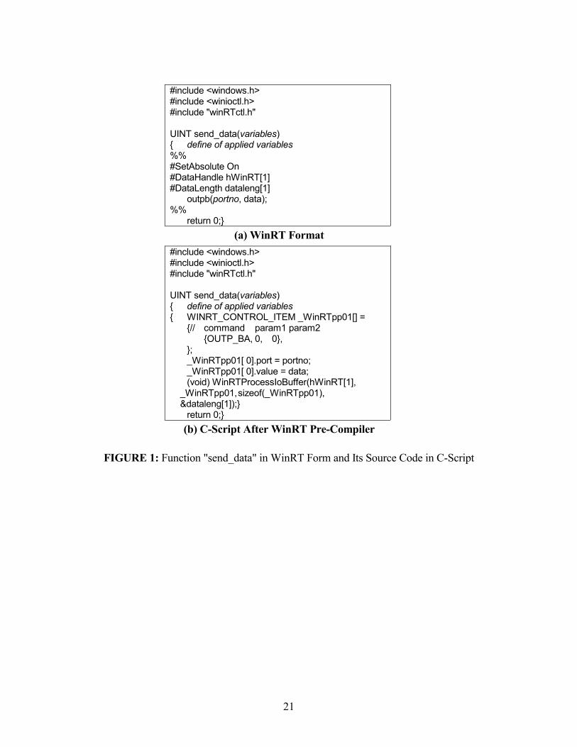
The basic I/O functions are implemented in Visual Studio C++ under Win32 applications.
The preprocessor commands (i.e. the commands outpb(), inpb() or outmb(), inmb() that send out
commands or read data through either ports or memories [20]) consist of a similar form of the one
used in DOS environment. After the pre-compiler is executed, WinRT translates the commands
between the sign �%%� into C-script that can be combined in regular Win32 source codes. Figure
1(a) shows an example of a function in WinRT form while Figure 1(b) shows the function in the
pre-compiled C-script. The default functions are defined in header file "WinRTctl.h" and bring up
the communication between Win32 applications and WinRT device driver. Similar steps are fol-
lowed to write functions for interrupts and DMA.
2.3 Timer
The most important feature in Control and Data Acquisition applications is the precision of
the timer. All the required functions from MSDN to set up precise timers under Windows NT are
introduced in this section.
Under DOS environment, a timer is usually set up using a software interrupt associated
with the on-board clock. The control algorithm is in the interrupt service subroutine and is called
when the �soft� timer sends out the interrupt request. As a protected OS, Windows NT does not
allow software interrupts, �interrupt 21h� [18]. Therefore accessing directly the on-board clock
and varying its frequency is not trivial.
Windows NT provides the ability to establish a timer that will interrupt the program at pe-
riodic intervals. When the timer sets off, the function will wake up a thread (i.e. a special defined

9
function) and runs the commands in it. There are two types of timers supported by Visual C++
under Windows NT. First one is a generic API function [21] while the other is defined in the Mul-
timedia Library (with API form) [16]. Both of them are implemented in Win32 under User Mode,
while the API timer works in the same mode and the Multimedia timer works in the Kernel Mode.
Another specification, very crucial from a Control point of view, is that the resolutions of both tim-
ers are 1 millisecond. Nevertheless, the precision of the API timer is 10 to 15 ms and above but the
one of Multimedia timer can be as fast as 5 ms and above. That is the reason that the multimedia
timer is used in this work and the sampling rate at 200 Hz is set. WinRT also supports its timer
function that works at Kernel Mode but it is similar to the multimedia timer [20]. The way to set
up the Multimedia timer will be explained in detail in Section 3.
MSDN library specifies that the maximum number of timers that can be activated for
Win32 application is 16 in one process [16]. Threads may be opened as many as needed to do ei-
ther data acquisitions or calculations, as long as the number of timers is below the limit. For
example, different sensors can be set up at different threads, then the data will be shared in another
thread and be used to calculate the compensating signal. For simplification and demonstration
purposes, data acquisitions, calculations, and sending out signals will be put in only one thread.
All the subroutines are located in the same application class file which is generated by
MFC (Microsoft Foundation Class) wizard. The header file < Mmsystem.h> must be included be-
fore the multimedia timer is being activated. Also Import Library <winmm.lib> has to be
included in the Visual C environment to make all the multimedia timer function accessible.
The target (desired) resolution of the timer is set as a global variable first as
�TARGET_RESOLUTION� in unit of millisecond. Since each machine and the OS platform may
have different range of the resolution (which means it may not meet the set-up requirement), the

10
minimum and maximum resolutions supported by the timer services would be determined at the
beginning of the subroutine that starts the timer session (void classname: OnControlMtctl()). The
function �timeGetDevCaps� fills the wPeriodMin and wPeriodMax members of the TIMECAP (as
a globally defined class TIMECAP tc) structure with the minimum and maximum resolutions. The
result will be saved back to another global variable wTimerRes (UINT, unsigned integer).
After the minimum resolution is established, the functions timeBeginPeriod and timeEnd-
Period must be used to set and clear this resolution. For each timeBeginPeriod being called, there
must be a matched timeEndPeriod in the program. An application can make multiple calls of
timeBeginPeriod with the same number of timeEndPeriod.
The sampling rate is set at every 5msec so that the timer function wakes the thread in this
work. A global variable UINT msInterval = 5 sets a 5msec delay between the executions of the
callback function when it is used in the function timeSetEvent that starts the timer. Though the
only limit of the interval is that it has to be greater than the timer resolution, the number cannot be
made less than 5 or the system goes unstable due to the time consumption of calculation. Also it is
pointed out by MSDN library that periodic timer events with an event delay of 10 milliseconds or
less consume a significant portion of CPU resources. (Usually the computer is fully dedicated to
the system control so that the CPU consumption is not a significant issue here.)
The function timeSetEvent needs the following inputs: uDelay (msInterval in the example
in Section 3), uResolution (wTimerRes), lpTimeProc (WakeThread in the example in Section 3),
dwUser (User-supplied callback data) and fuEvent(TIME_PERIODIC, because the repeated timer
is needed). The function returns an identifier UINT wTimerID, which is also passed to the callback
function, for the timer event if successful or an error otherwise. Since the timer is set periodically,
11
the function timeKillEvent is called to cancel the event. The identifier (wTimerID here) is specified
as an input of the function.
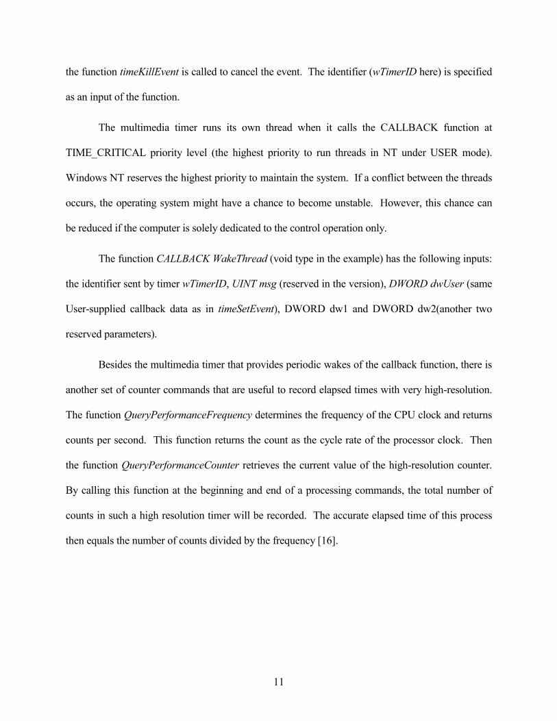
The multimedia timer runs its own thread when it calls the CALLBACK function at
TIME_CRITICAL priority level (the highest priority to run threads in NT under USER mode).
Windows NT reserves the highest priority to maintain the system. If a conflict between the threads
occurs, the operating system might have a chance to become unstable. However, this chance can
be reduced if the computer is solely dedicated to the control operation only.
The function CALLBACK WakeThread (void type in the example) has the following inputs:
the identifier sent by timer wTimerID, UINT msg (reserved in the version), DWORD dwUser (same
User-supplied callback data as in timeSetEvent), DWORD dw1 and DWORD dw2(another two
reserved parameters).
Besides the multimedia timer that provides periodic wakes of the callback function, there is
another set of counter commands that are useful to record elapsed times with very high-resolution.
The function QueryPerformanceFrequency determines the frequency of the CPU clock and returns
counts per second. This function returns the count as the cycle rate of the processor clock. Then
the function QueryPerformanceCounter retrieves the current value of the high-resolution counter.
By calling this function at the beginning and end of a processing commands, the total number of
counts in such a high resolution timer will be recorded. The accurate elapsed time of this process
then equals the number of counts divided by the frequency [16].

12
3 CONTROL ALGORITHM IN WinReC v.1
The control application program in WinReC v.1, the Windows NT based control software
developed at the Rutgers Robotics and Mechatronics Laboratory, consists of four parts: (1) the ini-
tialization of drivers and definition of interface card control commands at the beginning of the
program; (2) the initiation of the timer when the control of the robotic or mechatronic system
starts; (3) the control algorithm that is waked periodically; (4) the stop of the timer when the con-
trol of the system is canceled. Each one of these parts will be discussed in detail. The whole idea
of the program is demonstrated in the flow chart in Figure 2.
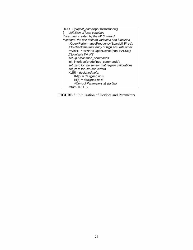
In order to take the full advantage of Windows multitasking feature, this project was set
with Windows frame. There are many different API (or MFC) classes created by MFC wizard in
the skeleton project. These classes inherit the different configurations in order to generate a (or
multiple) frame window(s). All the necessary variables, functions that initiate the driver(s) as well
as globally recognized parameters are defined at the starting point of the program so that they are
set ready right after the frame window begins. The starting point is in the class CProjectnameApp
at both constructor CprojectnameApp::CProjectnameApp and BOOL type function Cproject-
nameApp::InitInstance(). It is recommended to put all significant initialization in latter function as
in Figure 3.
As it is described in Section 2, the timer has to be set in order to trigger the control algo-
rithm periodically. Once the MFC generates a command in the menu
(Cproject_nameApp::OnControlMtctl() in Figure 4), the least resolution of the timer can be deter-
mined at the beginning of the function. Then the timer resolution is established through
timeBeginPeriod. If needed, the higher accurate timer also can be used to record the elapsed time.

13
Then the periodic multimedia timer is set to start with the command timeSetEvent, which returns
an identifier (wTimerID) required when the timer is terminated.
After the timer is initiated, the computer calculates the signals that actuate individual sys-
tem motors in each iteration. The computer receives the measurements of actual joint angles
through encoder and the interface card. Then the computer calculates the differences between the
measurements and desired positions, and uses them and the differences from the previous step
along with the accumulations of integral control signal from the beginning, to generate the outputs
for the current step. The entire control algorithm is illustrated in Figure 5. Similar algorithms have
been implemented for more advanced controllers such as LQR and H2.
The timer terminator is in another command function
(Cproject_nameApp::OnControlMtctloff in Figure 6). Here the timer is stopped by execute the
command timKillEvent(wTimerID). At the same time, the resolution of the timer should be deleted
from the program if it is not required by other timer routines. The experimental data can be re-
corded at this point and be analyzed by other software such as MATLAB®.
4 EXPERIMENTAL SYSTEMS AND DEMONSTRATIONS
The method presented in this paper and WinReC v.1, the software that was developed
based on this method, were tested experimentally using two complex robotic / mechatronic sys-
tems. Several controllers including LQR and H2 were implemented. Extensive tests for almost two
years have been performed and all systems and controllers performed extremely well, with no un-
stabilities or system failures. In this section we present some examples from these experimental
tests.

14
4.1 Experimental System Setup
The Dell® OptiPlex Gxa� PC system with INTEL® Pentium II� 333 MHz CPU and 128
MRAM is used in this work. It is augmented with two US Digital® PC7166� PC to incremental
encoder interface cards and two Datel® PC-412C� Analog I/O boards. The PC collects the sensor
readings either through the data acquisition boards or the encoder interface cards, does the feed-
back control calculation, and then sends out the signal to the actuators of the electro-mechanical
systems through the D/A converter and laboratory built amplifiers.
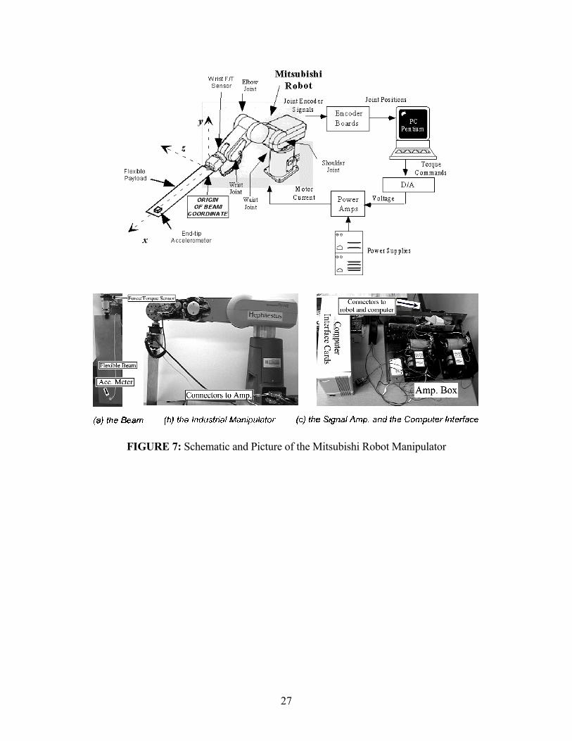
The first electromechanical system that is used in this paper to demonstrate the effective-
ness of WinReC v.1 is a five-degree-of-freedom Mitsubishi RV-M2 manipulator. Figure 7 shows
all mechanical and electrical components of this experimental system. A JR3® 67M25 6-axis
force/torque sensor is placed at the manipulator wrist before the gripper. The manipulator gripper
is holding a flexible beam to study vibration suppression of the payload using the robot manipu-
lator. An Entran Accelerometer (Model EGE-732B-2000D-/RS), which is a strain gauge type
sensor, is attached at the free-end of the flexible beam to record the beam's oscillations [22].
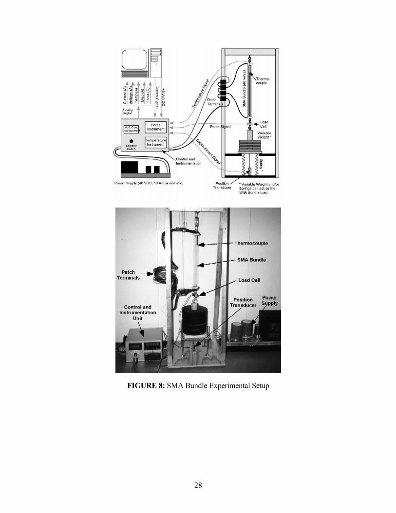
The second electromechanical system is a Shape Memory Alloy Wire Bundled actuator,
shown in Figure 8. This system was constructed consisting of 48, 12 in. (30.5 cm) long, 0.006 in.
(150 µm) diameter wires. The wires that make up the bundle are fabricated from a Nickel-
Titanium (Ni-Ti) alloy made by Dynalloy, Inc and they are manufactured such that they undergo a
maximum length contraction of 8% and can apply a considerable amount of force compared to
their weight. Different sensors were applied in this mechatronic system to measure force, position,
current and temperature. A complete description of the design and fabrication of the actuator can
be found in [23].

15
4.2 Experimental Control Demonstrations
4.2.1 Position Control of an Industrial Robot Manipulator
In this experiment, independent joint PID control of the Mitsubishi RV-M2 manipulator is
demonstrated. In independent joint PID control, each joint is controlled separately. The inputs for
each motor are specified either directly in joint space by using desired joint angles, or in Cartesian
space by defining desired end-effector positions and orientations and then calculating the equiva-
lent joint angles by using the inverse kinematic model. In this example, the desired angles are
specified directly in joint space. All the non-linear coupling effects from other joints and the grav-
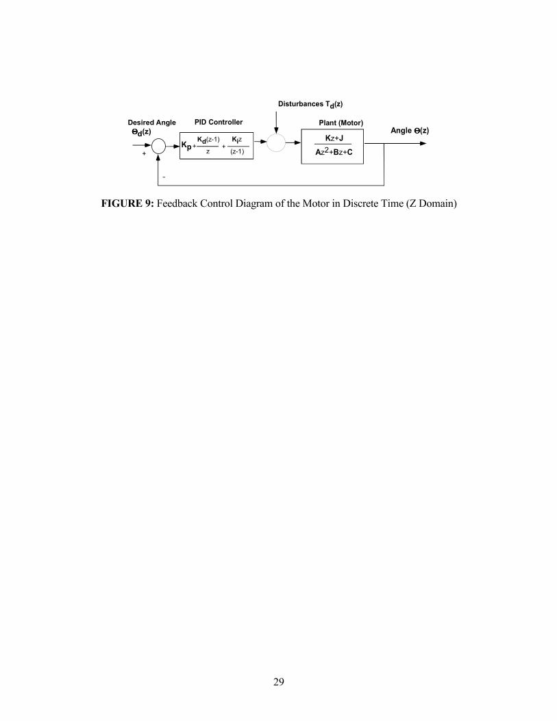
ity effect are treated as disturbances in the controller. Digital control techniques have been used to
design the PID controller for each motor. Each motor is considered to be a second order system.
Figure 9 shows the block diagram of the controller in Z-domain.
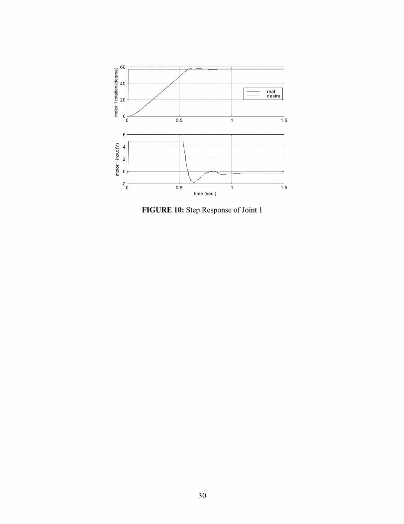
Figure 10 shows an example of a step response and the control voltage for joint 1 of the
Mitshubishi RV-M2. The motor moves from the initial position at 0° to the final position of 57.3°
(1 radian) in 0.55 sec. Similar responses are obtained for all other joints, when they move inde-
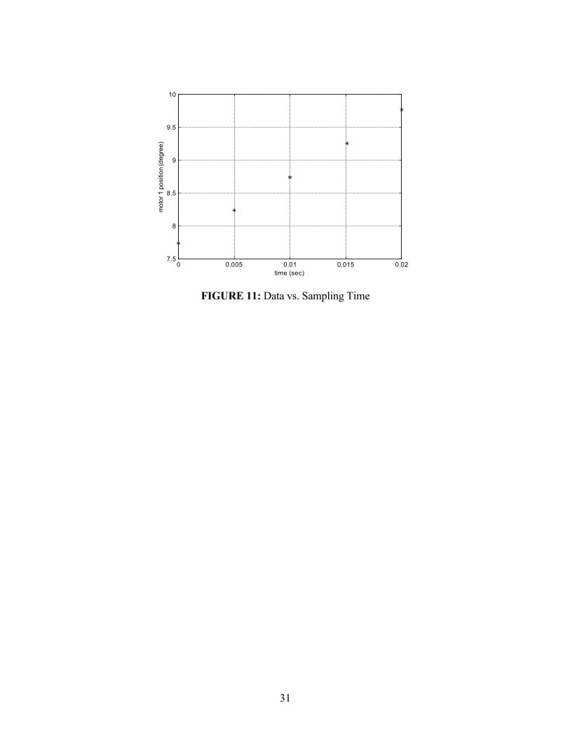
pendently or when they move jointly to position the end-effector at a desired location. Figure 11
shows the occurrence of data from joint 1 with respect to the sampling time. It indicates that the
timer of 5msec interval is very accurate because the elapse time of the response was recorded by
applying a high-resolution counter separately, as it is described in Section 2.
To demonstrate the ability to set up different timers simultaneously, an example is shown
where a second timer is incorporated to perform path following tests. The calculation of the joint
trajectories with respect to time starts after the second timer is executed. Setting the interval at
50msec and the same resolution with the first timer, the calculated trajectories become the desired
positions of motors in the next step of the control routine. Figure 12 shows a path following test

16
for the first motors. In this example the trajectory is accomplished in 3 sec. Since the timer should
be terminated when the trajectory profiles are achieved, the function timeKillEvent is placed at the
logic loop inside the CALLBACK subroutine.
4.2.2 Payload Vibration Suppression Control by an Industrial Robot Manipulator
Advanced controllers such as LQR and H2, have also been implemented with WinReC v.1.
In these series of experiments, the Mitshubishi RV-M2 manipulator, handles a thin flexible beam
as it is shown in Figure 7. The wrist mounted force/torque sensor provides control feedback for the
payload vibrations. Two types of advanced controllers to suppress the payload vibrations are
designed using LQR and H2 methods. The vibrations of the flexible payload with only PID joint
position control without vibration suppression scheme and two sets with the payload vibration
suppression controllers are collected using the accelerometer mounted at the end-tip of the flexible
beam. The positions of the beam�s end-tip are calculated by two integrations with respect to time
and are shown in Figure 13. Details from these experiments can be found in [22].
4.2.3 Open Loop Control of an SMA Wire Bundled Actuator
The SMA Bundle was tested through open loop experiments using the setup described in
Section 4.1. For the open loop experiments described in this paper, a variable weight without
springs acted as the load. The specific weights used were 11 lbs. (4.99 kg) and 27.5 lbs. (12.5 kg).
Several different types of input signals (step, ramp, sinusoid, and half sinusoid) were defined in
WinReC v.1 and then sent to the SMA Bundle. Each experimental run lasted approximately 24
seconds during which the following data were recorded: SMA bundle voltage drop, current, con-
traction, and air temperature at the center of the bundle. In this paper, some results from the step
responses are presented. The algorithm that is being used for the open loop tests is very similar to

17
the one used for closed loop control experiments as it was presented in Section 2. After the timer
is initiated, the CALLBACK function that records the measurement is activated after each interval.
A complete set of data for three different step input signals with an 11 lb. load is shown in Figure
14. The algorithm discussed in this paper resulted in excellent experimental data and allowed a
detailed analysis of the SMA bundle performance. An in depth analysis of the bundle results is pre-
sented in [23].
5 CONCLUSIONS
In this paper, a generic method is introduced to write a software program to use the inex-
pensive and popular Windows NT platform to perform control and data acquisition processes. A
standard protocol of setting up periodic timers with Microsoft Visual C++ library has been estab-
lished. Applications of all the required functions from Microsoft Foundation Class® to set up
periodic timers are described in detail and demonstrated in the examples. The examples of apply-
ing the timers associated with the commercial device driver WinRT for ISA and other types of
interface cards indicates nice performance on closed loop control of robot manipulator as well as
the accuracy of open loop control for the SMA bundled actuator. The methods generated in this
paper can be used to implement even more complicated control algorithms such as state-space con-
trollers or adaptive control.
6 ACKNOWLEDGMENTS
This work was supported by a Johnson and Johnson Discovery Award. The authors would
like to thank Mr. Michael Mosley for his contributions in the design and fabrication of the SMA
bundle actuator.
18
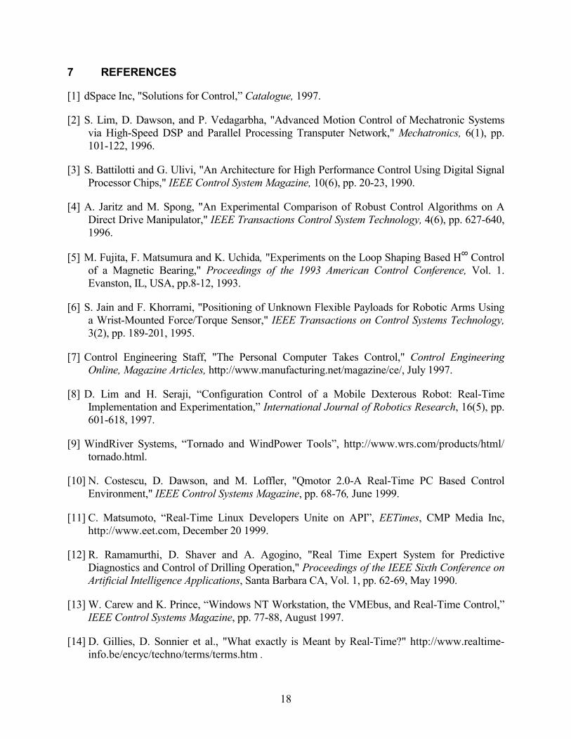
7 REFERENCES
[1] dSpace Inc, "Solutions for Control,� Catalogue, 1997.
[2] S. Lim, D. Dawson, and P. Vedagarbha, "Advanced Motion Control of Mechatronic Systems via High-Speed DSP and Parallel Processing Transputer Network," Mechatronics, 6(1), pp. 101-122, 1996.
[3] S. Battilotti and G. Ulivi, "An Architecture for High Performance Control Using Digital Signal Processor Chips," IEEE Control System Magazine, 10(6), pp. 20-23, 1990.
[4] A. Jaritz and M. Spong, "An Experimental Comparison of Robust Control Algorithms on A Direct Drive Manipulator," IEEE Transactions Control System Technology, 4(6), pp. 627-640, 1996.
[5] M. Fujita, F. Matsumura and K. Uchida, "Experiments on the Loop Shaping Based H∞ Control of a Magnetic Bearing," Proceedings of the 1993 American Control Conference, Vol. 1. Evanston, IL, USA, pp.8-12, 1993.
[6] S. Jain and F. Khorrami, "Positioning of Unknown Flexible Payloads for Robotic Arms Using a Wrist-Mounted Force/Torque Sensor," IEEE Transactions on Control Systems Technology, 3(2), pp. 189-201, 1995.
[7] Control Engineering Staff, "The Personal Computer Takes Control," Control Engineering Online, Magazine Articles, http://www.manufacturing.net/magazine/ce/, July 1997.
[8] D. Lim and H. Seraji, �Configuration Control of a Mobile Dexterous Robot: Real-Time Implementation and Experimentation,� International Journal of Robotics Research, 16(5), pp. 601-618, 1997.
[9] WindRiver Systems, �Tornado and WindPower Tools�, http://www.wrs.com/products/html/ tornado.html.
[10] N. Costescu, D. Dawson, and M. Loffler, "Qmotor 2.0-A Real-Time PC Based Control Environment," IEEE Control Systems Magazine, pp. 68-76, June 1999.
[11] C. Matsumoto, �Real-Time Linux Developers Unite on API�, EETimes, CMP Media Inc, http://www.eet.com, December 20 1999.
[12] R. Ramamurthi, D. Shaver and A. Agogino, "Real Time Expert System for Predictive Diagnostics and Control of Drilling Operation," Proceedings of the IEEE Sixth Conference on Artificial Intelligence Applications, Santa Barbara CA, Vol. 1, pp. 62-69, May 1990.
[13] W. Carew and K. Prince, �Windows NT Workstation, the VMEbus, and Real-Time Control,� IEEE Control Systems Magazine, pp. 77-88, August 1997.
[14] D. Gillies, D. Sonnier et al., "What exactly is Meant by Real-Time?" http://www.realtime-info.be/encyc/techno/terms/terms.htm .

19
[15] Microsoft Corp., "Real-Time Systems and Microsoft Windows NT", Microsoft MSDN Lib., 1995.
[16] Microsoft Corp., "About Multimedia Timers," Microsoft MSDN Library, Platform SDK, 1998.
[17] Microsoft Corp., "Microsoft NT Workstation 4.0, System Requirement," http://microsoft.com/ntworkstation .
[18] Microsoft Corp., "Windows NT 4.0 DDK, Kernel Mode Drivers, Design Guide," Microsoft MSDN Library, 1998.
[19] J. Hanrahan, "Windows NT/Windows 2000/WDM Driver FAQ," Kernel Mode Systems, San Diego CA, http://www.cmkrnl.com/faq.html .
[20] Blue Water Systems Inc, WinRT Version 3.0, Users Manual, 1998.
[21] H. Schildt, Windows NT 4 Programming from the Ground Up, Osborne McGraw-Hill, 1997.
[22] C. J. Lee and C. Mavroidis, �Discrete-Time LQR and H2 Damping Control of Flexible Payloads Using a Robot Manipulator with a Wrist-Mounted Force/Torque Sensor,� DSC-Vol. 69-2, Proceedings of the 2000 ASME International Mechanical Engineering Congress and Exposition, Dynamic Systems and Control Division, Orlando, FL, pp. 997-1004, November 5-9, 2000.
[23] M. Mosley and C. Mavroidis, �Experimental Non-Linear Dynamics of a Shape Memory Alloy Wire Bundle Actuator", Journal of Dynamic Systems, Measurement and Control, Transactions of the ASME, Vol. 123, No. 1, pp. 103-112.

20
LIST OF FIGURES
FIGURE 1: Function "send_data" in WinRT Form and Its Source Code in C-Script
FIGURE 2: Flow Chart of the Control Algorithm in WinReC v.1
FIGURE 3: Initilization of Devices and Parameters
FIGURE 4: Timer Start Function
FIGURE 5: Control Algorithm CALLBACK Function
FIGURE 6: Timer Stop Function
FIGURE 7: Schematic and Picture of the Mitsubishi Robot Manipulator
FIGURE 8: SMA Bundle Experimental Setup
FIGURE 9: Feedback Control Diagram of the Motor in Discrete Time (Z Domain)
FIGURE 10: Step Response of Joint 1
FIGURE 11: Data vs. Sampling Time
FIGURE 12: Trajectory Following Response of Joint 1
FIGURE 13: Comparison of Three Different Controllers in Suppressing Vibrations of a Flexible Payload Handled from the Mitsubishi Robot Manipulator
FIGURE 14: Step Input Signal, 11 lb. Load
21
#include <windows.h> #include <winioctl.h> #include "winRTctl.h" UINT send_data(variables) { define of applied variables %% #SetAbsolute On #DataHandle hWinRT[1] #DataLength dataleng[1] outpb(portno, data); %% return 0;}
(a) WinRT Format #include <windows.h> #include <winioctl.h> #include "winRTctl.h" UINT send_data(variables) { define of applied variables { WINRT_CONTROL_ITEM _WinRTpp01[] = {// command param1 param2 {OUTP_BA, 0, 0}, }; _WinRTpp01[ 0].port = portno; _WinRTpp01[ 0].value = data; (void) WinRTProcessIoBuffer(hWinRT[1],
_WinRTpp01, sizeof(_WinRTpp01), &dataleng[1]);}
return 0;} (b) C-Script After WinRT Pre-Compiler
FIGURE 1: Function "send_data" in WinRT Form and Its Source Code in C-Script

22
CProject_nameApp::OnControlMtctl()
Yes
No
Done
CProject_nameApp::OnControlMtctloff()
CALLBACK WakeThread()
ContinueControl Algorithm
Stop Timer
Save Data
Start Timer∆T = 5 ms
CProject_nameApp::InitInstance()
(1)
(2)
(3)
(4)
FIGURE 2: Flow Chart of the Control Algorithm in WinReC v.1
23
BOOL Cproject_nameApp::InitInstance() { definition of local variables // first: part created by the MFC wizard // second: the self-defined variables and functions ::QueryPerformanceFrequency(&cardctl.liFreq); // to check the frequency of high accurate timer hWinRT = ::WinRTOpenDevice(han, FALSE); // to initiate WinRT set up predefined_commands init_interface(predefined_commands); set_zero for the sensor that require calibrations set_zero for D/A converters Kp[5] = designed no�s;
Kd[5] = designed no�s; Ki[5] = designed no�s; //Control Parameters at starting
return TRUE;}
FIGURE 3: Initilization of Devices and Parameters

24
void Cproject_nameApp::OnControlMtctl() { // define local variables if (::timeGetDevCaps(&tc, sizeof(TIMECAPS)) != TIMERR_NOERROR) { // Error; application can't continue }
wTimerRes = min(max(tc.wPeriodMin, TARGET_RESOLUTION), tc.wPeriodMax);
// find the least timer resolution
::timeBeginPeriod(wTimerRes); // establish the timer resolution // set the necessary parameters equal to zero before the controller starts
::QueryPerformanceCounter(&cardctl.liStart); // start the higher accurate timer to record the elapse time wTimerID = timeSetEvent( msInterval, wTimerRes, WakeThread, // name of the control algorithm (DWORD) dwUser, TIME_PERIODIC ); }
FIGURE 4: Timer Start Function

25
void CALLBACK WakeThread(UINT wTimerID, UINT msg, DWORD dwUser, DWORD dw1, DWORD dw2) {// Part 1: Collect Data read_encoders; read_sensors; // Part 2: Calculate Compansating Outputs desire_data; error = desire_data - current_data; error_sum = error_sum + Ki*error; compensate = Kp*error + Kd*(error-error_old) + error_sum; error_old = error; //Part 3: Output Signals sendout_compensate; // recording the elapse time through the timer interval and all the calculation by // higher resolution timer ::QueryPerformanceCounter(&cardctl.liStart); cardctl.time_interval =(double)(cardctl.liFinish.LowPart - cardctl.liStart.LowPart) /(cardctl.liFreq.LowPart); ::QueryPerformanceCounter(&cardctl.liStart); //Part 4: Save Data if (datano<=14999) { savedata(datano) = current_data; } }
FIGURE 5: Control Algorithm CALLBACK Function

26
void Cproject_nameApp::OnControlMtctloff() { define local variable ::timeKillEvent(wTimerID); // stop the periodic timer ::timeEndPeriod(wTimerRes); // erase the timer resolution set_zero D/A outputs save data}
FIGURE 6: Timer Stop Function
27
FIGURE 7: Schematic and Picture of the Mitsubishi Robot Manipulator
28
FIGURE 8: SMA Bundle Experimental Setup
29
Kz+JAz2+Bz+C
KpKd(z-1)
z
Kiz
(z-1)+ +
-
+
Angle ΘΘΘΘ(z)Plant (Motor)PID Controller
Disturbances Td(z)
Desired AngleΘΘΘΘd(z)
FIGURE 9: Feedback Control Diagram of the Motor in Discrete Time (Z Domain)
30
0 0.5 1 1.50
20
40
60
mot
or 1
rota
tion
(deg
ree)
realdesire
0 0.5 1 1.5-2
0
2
4
6
mot
or 1
inpu
t (V
)
time (sec.)
FIGURE 10: Step Response of Joint 1
31
0 0.005 0.01 0.015 0.027.5
8
8.5
9
9.5
10
time (sec)
mot
or 1
pos
ition
(deg
ree)
FIGURE 11: Data vs. Sampling Time

32
0 0.5 1 1.5 2 2.5 3 3.50
20
40
60
80
100
mot
or 1
rota
tion
(deg
ree)
realdesire
0 0.5 1 1.5 2 2.5 3 3.5-1
0
1
2
3
mot
or 1
inpu
t (V
)
time (sec.)
FIGURE 12: Trajectory Following Response of Joint 1

33
0 1 2 3 4 5 6
-0.1
-0.05
0
0.05
0.1
time (sec.)
tip-d
is. (
m)
PD(no torque feedback)lqrh2
FIGURE 13: Comparison of Three Different Controllers in Suppressing Vibrations of a Flexible Payload Handled from the Mitsubishi Robot Manipulator

34
FIGURE 14: Step Input Signal, 11 lb. Load