PREPARATION OF TRANSFORMER SPECIFICATIONS By VALLAMKONDA SANKAR P.Eng. E-mail: [email protected].
23
PAYSON CITY POWER AND LIGHT
Electrical Construction
Standard Specifications
Revised January 27, 2005

Payson City Power Standard Specifications
January 27, 2005
24
Table of Contents
4-2.1 Purpose ........................................................................... Error! Bookmark not defined.
4-2.2 Codes and Ordinances................................................................................................... 26
4-2.3 Changes or Conflicts in Requirements and Guidelines ................................................ 26
4-2.4 Application for Services ............................................................................................... 27
4-2.5 Types of Service ........................................................................................................... 27
4-2.6 Approval for Service ..................................................................................................... 28
4-2.6.1 Inspection Check List ............................................................................................... 28
4-2.6.1.1 Subdivision (for details, sizes refer to spec book) ............................................ 28
4-2.6.1.2 Final If Materials Purchased From Payson City ............................................... 29
4-2.6.1.3 Final If Materials Provided By Contractor ....................................................... 29
4-2.6.1.4 Services ............................................................................................................. 29
4-2.7 Permanent Service Connection ..................................................................................... 29
4-2.8 Seals .............................................................................................................................. 30
4-2.9 Work Activity near High Voltage Overhead Power Lines ........................................... 30
4-2.10 Services ......................................................................................................................... 30
4-2.11 Working Space .............................................................................................................. 30
4-2.12 Sealing of Cabinets and Gutters .................................................................................... 31
4-2.13 Conductor Identification ............................................................................................... 31
4-2.14 Location of Meters ........................................................................................................ 32
4-2.15 Temporary Service ........................................................................................................ 32
4-2.16 Disconnection And Reconnection Of Service .............................................................. 32
4-2.17 Customer Equipment On Utility Poles ......................................................................... 32
4-2.18 Overhead Service, 480 Volts And Under, Service Drop ............................................. 32
4-2.19 Multiple-Unit Residential Overhead Service ................................................................ 33
4-2.20 Nonresidential Overhead Service ................................................................................. 33
4-2.21 Overhead Service to Manufactured Homes with Factory Installed Meter Bases ......... 33
4-2.22 Underground Service, General ..................................................................................... 33
4-2.23 Trenches, Conduit and Backfill Provided By The Customer ....................................... 33
4-2.24 Depth ............................................................................................................................. 34
4-2.25 Backfill .......................................................................................................................... 34

Payson City Power Standard Specifications
2/28/2017
25
4-2.26 Joint Use........................................................................................................................ 34
4-2.27 Conduits ........................................................................................................................ 35
4-2.28 Clearances From Swimming Pools ............................................................................... 35
4-2.29 Underground Service To Residential, subdivisions ...................................................... 36
4-2.30 Nonresidential Underground Service ............................................................................ 40
4-2.31 Service at Primary Voltage General ........................................................................... 40
4-2.32 Customer Equipment .................................................................................................... 40
4-2.33 Utility Equipment.......................................................................................................... 41
4-2.34 Painting of Utility Equipment....................................................................................... 41
4-2.35 4-2.35 Padmount Transformer specifications ............................................................. 42
4-2.36 Street Light Specifications ............................................................................................ 43
4-2.37 Splice Box and Connector Specification ...................................................................... 43
4-2.38 Sectionalizing Enclosures Specifications ..................................................................... 43
Payson City Power Standard Specifications
2/28/2017
26
4-2.1 Purpose
This manual was prepared to aid developers, contractors and engineers in establishing electric
service for new and remodeled structures. We recognize that you may require personal
assistance from our staff, and we encourage you to contact us by calling Payson City Power and
Light at 465-5274 to discuss your electric service requirements with us. Additional copies of this
manual are available at Payson City offices at 439 West Utah Ave. or at 1100 North 100 East at
Payson Power and Light Shop. It is the desire of Payson Power and Light, and the local electrical
code enforcing authority to provide you, the Customer (developers, contractors, owners etc.),
with high-quality, safe electric service.
In order to avoid unnecessary repetition, the word "Utility" as used in the following pages shall
mean Payson City Power and Light.
The requirements of this manual are intended to apply to relocated services, rewired services,
and house moves, as well as to new services, unless a specific exception is granted.
4-2.2 Codes and Ordinances
It is necessary that the construction of new or, remodeled installations conform to applicable
provisions of the National Electrical Code (NEC), National Electrical Safety Code (NESC), and
Payson City codes. This includes OSHA rules both during construction and maintenance.
Provision for qualifications of contractors, bonding, permits, inspection, fees, etc., are outlined in
chapter 13 of the Payson City Ordinances and resolutions shall apply here-in. Items contained
therein that must be complied with relating to electrical distribution construction include:
Obtaining a business license
Inspections
Obtaining permits
Penalties for violations
Power line extension fees
Customer deposits Electrical connection fees
Metering
4-2.3 Changes or Conflicts in Requirements and Guidelines
These requirements and guidelines are issued with the intent of complying with all applicable
codes, ordinances, regulations, and tariffs; however, in the case of conflict, the appropriate
regulation, tariff, code, or ordinance will supersede the interpretation offered in this manual. In
addition, these, requirements are subject to change in the event that the governing codes,
ordinances, regulations, or tariffs are changed. The Utility does not assume responsibility for
keeping this manual current and should be consulted in case of doubt on the applicability of any
item.
The phrase "consult Utility" as used in this manual shall mean a consultation with Payson City
Power and Light is to be made for each and every installation or project.
Payson City Power Standard Specifications
2/28/2017
27
4-2.4 Application for Services
It is important the Utility be provided as early as possible with accurate load information and the
date when the Customer will require service, so all necessary arrangements for the service may
be completed. Requests for service to commercial and industrial customers normally require 60
days advance planning by the Utility in order to serve the load. Installations requiring
transformers or other equipment not in stock require six months lead time or more.
For commercial, industrial, residential subdivisions, mobile home parks, and apartment complex
applications, the requests for service shall include a plot plan. Commercial, industrial or plot
plans should show preferred service and meter, location, and single line diagram of the electrical
layout. The request must show all load information, including lighting, receptacle, water heating,
cooking, electric heat, air conditioning, and motor loads, plus sufficient information on
equipment operations to allow the kilowatt demand of the load to be estimated.
The Utility has a staff available to provide advice on service requirements and related problems
relative to electric energy utilization for new, existing, and reconstructed installations. The
Customer or the Contractor will be held liable for any damage to Utility equipment or personal
injury unless adequate notice is given to the Utility and approval is granted regarding the change
or addition.
When conditions are encountered during construction that require changes in the service
arrangements, the Utility must be consulted so mutually satisfactory alternate arrangements can
be made. Communication with the Utility will bring this service to you.
All Utilities such as Cable TV, Phone, Gas, etc. must be contacted after approval for service
has been given.
4-2.5 Types of Service
The electric service available is 60 hertz (cycles), alternating current, single or three-phase. The
secondary voltages and connections available are given below:
1. Overhead Service
2. Single-phase, 120/240 volt, three-wire, grounded
3. Three-phase, 208Y/120 volt, four-wire, grounded, wye
4. Three-phase, 480Y/277 volt, four-wire, grounded, wye
5. Under certain conditions, at the option of the Utility the following services may be
supplied:
6. Single-phase, 240/480 volt, three-wire, grounded
7. Three-phase, 240/120 volt, four-wire, grounded delta
8. Three-phase, 480/240 volt, four-wire delta
9. Underground Service
10. Single-phase, 120/240 volt, three -wire, grounded
11. Three-phase, 208Y/120 volt, four-wire, grounded, wye
12. Three-phase, 480Y/277 volt, four-wire, grounded, wye
Payson City Power Standard Specifications
2/28/2017
28
The nominal primary voltage of the Utility's distribution system may differ from under certain
conditions. Primary delivery will be at the distribution voltage standard for the location at which
it is requested.
4-2.6 Approval for Service
It is required that an electrical installation be approved by the Building inspector before it can be
energized by the Utility. The service will be energized by the Utility only after all service
requirements have been met.
4-2.6.1 Inspection Check List
4-2.6.1.1 Subdivision (for details, sizes refer to spec book)
1. Provide an electronic map of subdivision
2. Approved plan must be completed prior to pre-construction meeting
3. Property corners permanently marked in concrete
4. Map must denote sidewalk being Monolithic, park strip or none
5. Trenching 2’ behind walk
6. 4’ top of conduit for primary from final grade
7. 2’ separation between communication and power with power closest to the
sidewalk
8. Warning tape placed 2’ above power conduit
9. All 90’s need to be 36” sweeps
10. Conduit for UTOPIA must be orange color which stays with communication
11. Flat bottom trench
12. Road sleeves for conduit min of 70 feet in length and need to be in line with
back of walk
13. Shading Conduit with sand if native soil has rocks larger than 4”(get direction
from inspector)
14. 90’s are stubbed up and placed 2’ off front and side of property line
15. Communication equipment is located on a different property corner other
than power
16. All conduits are capped
16.a Schedule 40 End Bell Couplings installed at end of conduit.
17. All future stubs need marker flags (available through Payson City)
18. Electrical conduit is gray schedule 40 pvc, communication use a different
color
19. Under all electrical sleeves and equipment need gravel 1”minus
20. Secondary junction boxes need to be equivalent with Carson or Carlon with
twist locking latch.
21. Transformer, switch and ground sleeves need to be 4 to 6 inches above back
of walk and level
22. Secondary junction boxes need to be 2-3 inches above final grade and level
23. Street light location needs to be verified before installation
24. Street light foundation needs to be level and bolts need to be above grade
25. Conduit for streetlight follows the secondary conduit and 90’s in to streetlight
foundation.
Payson City Power Standard Specifications
2/28/2017
29
26. Conduit needs to be 2-4”above gravel inside and in the middle of the opening
of transformer sleeves and secondary junction boxes
27. Mule tape installed inside of all Primary conduit
28. Three phase transformer pad needs to be 6” above grade with #4 rebar with 1’
center mat. Require dimensions for pad from Payson City. 1 1/2’ separation
between secondary and primary conduits in the pad
29. Metering ( transformer or Building)
4-2.6.1.2 Final If Materials Purchased From Payson City
1. Secondary wire pulled in and extended 3’above box
2. Secondary junction boxes terminated to manufacturing torque specifications
3. Secondary terminator connectors need to be pre lubed and meet specifications
4. Streetlights installed including poles, head, wire and all connections made up
4-2.6.1.3 Final If Materials Provided By Contractor
1. Transformers need to have all insulated secondary connectors, busbars and
well bushings installed and tight, transformer tank ground lugs (2).
2. #6 bare copper attached to the ground rod and transformer tank ground
connector.
3. Transformer secured to sleeve
4. Secondary terminated in transformer
5. All primary terminators must meet specifications
6. All ground sleeves and switch boxes must meet specifications
7. Secondary wire pulled in and extended 3’above box
8. Secondary junction boxes terminated to manufacturing torque specifications
9. Secondary terminator connectors need to be pre lubed and meet specifications
10. Streetlights installed including poles, head, wire and all connections made up
4-2.6.1.4 Services
1. Trench 2’ from top of conduit to final grade
2. 36” sweep 90’s
3. Attached to existing secondary conduit stub (stub may need to be adjusted to
be straight)
4. Trench flat and straight from junction to meter base
5. Meter base location (see specifications)
6. Check service connections to be tight and dioxide.
7. Meter hub on service conduit
8. Service conduit for UTOPIA
4-2.7 Permanent Service Connection
Only authorized Utility employees shall make the permanent (or temporary) connection or
disconnection of the Utility's electric service to a building or structure.
Payson City Power Standard Specifications
2/28/2017
30
4-2.8 Seals
The purpose of seals placed by the Utility on meters and associated service equipment is to
prevent injury and/or tampering.
Under normal circumstances, seals are not to be removed except by the Utility. If an emergency
should require seal removal (only by authorized electrical contractors) without prior notification,
the Utility must be notified as soon as possible, so the installation can be inspected and the seal
replaced. When this occurs, the party removing the seal shall accept all liability for damage or
alteration to equipment, injury to persons or property, and loss of revenue to the Utility. From
the time the seal is removed until 72 hours after the Utility has been notified that the equipment
is ready to be re-sealed.
4-2.9 Work Activity near High Voltage Overhead Power Lines
As set forth in Section 54-8c-1 through 54-8c-7 of the Utah Code, no person or thing may be
brought within 10 feet of any high voltage overhead power line unless:
1. The responsible party has notified the Utility operating the high voltage line of the
intended activity; and
2. The responsible party and the Utility have completed mutually satisfactory safety
precautions for the activity; and
3. The responsible party has made prior arrangements to pay the Utility for the mutually
satisfactory safety precautions (if applicable).
The Utility recommends a minimum of 3 business day's notice be given before any work near its
lines is scheduled to begin.
NOTE: The National Electrical Safety Code requires that homes, buildings, bridges, signs,
antennas, etc. have sufficient horizontal and vertical clearance to overhead power lines.
Consult with the Utility for applicable distances.
4-2.10 Services
The location of the service entrance on the Customer's premises is an important consideration to
both the Customer and the Utility. The location where the developer or contractor metered
service is ten (10) feet (five feet preferred) from the front on the side of the house. The location
where the developer or contractor attaches to the City Electrical system shall be determined by
the Utility.
The Utility shall be consulted in order to designate the point of attachment for overhead service
drops, underground service laterals.
For secondary voltage service, the Utility will provide, install, and maintain meters. The
Customer will provide, install, and maintain all service equipment, including switches, service
entrance conductors, raceways, enclosures, and meter sockets, and will provide right - of - way
and space for the installation and maintenance of the Utility facilities.
4-2.11 Working Space
To permit access to metering installations and to provide safety for Personnel, a working and
standing space entirely on the property of the customer is to be provided in front of all meter
socket(s). All clearances must be at least as shown below.

Payson City Power Standard Specifications
2/28/2017
31
Figure 4-2.11-1 Minimum Clearances around Meters
NOTE:
Maintain a three (3) foot minimum radius form gas meter to electrical meter base. The
customer will furnish, install and maintain or make a contribution in aid of construction to
the Utility at the Utility option for permanent barricades to provide protection where the
working space is exposed to vehicles or hazardous conditions. The determination of need,
type, size and location of barricades is at the sole discretion of the Utility.
All service entrance conductors must be installed in continuous rigid galvanized steel or
IMC. Electrical grade PVC schedule 40 may only be used below ground. Risers will be
rigid galvanized steel or IMC for the first 10 feet then PVC schedule 40 maybe used up the
pole.
All rigid galvanized steel or IMC conduit will be supported with a wrapped rigid
galvanized steel or IMC 36 inch sweep 90.
4-2.12 Sealing of Cabinets and Gutters
All cabinets and gutters containing unmetered conductors, other than mainline switches required
by applicable electrical codes, must be arranged for sealing with the Utility's seal. Removable
conduit fittings may be installed between the service outlet and the meter when approved by the
Utility. These fittings must be visible from the meter location or from an exterior ground
position and must be arranged for sealing.
Unmetered conductors passing through a service disconnect compartment in mobile home
service equipment must be in an enclosed raceway and arranged for sealing.
4-2.13 Conductor Identification
Neutral shall be identified with the color white. In a four-wire delta service, the conductor with
the higher voltage to ground will be identified with the color orange.
3' MIN
3' MIN
1/4" Air Space Req.
Area to be
Kept Unobstructed
Top View FrontView
3' Min
5'6"
10" Min
3' Min
Roof Overhang
Ceiling or
Other Obstruction
Wall or Other
Obstruction
Closest Part
of Gasline
or Meter
3' Radius

Payson City Power Standard Specifications
2/28/2017
32
4-2.14 Location of Meters
Suitable space and provisions for mounting meter bases must be provided by the customer at a
location acceptable to the Utility. Residential Meters should be located on the side within the
front 10 feet (preferred 5 feet from front).
The center of any meter socket located outdoors on structures shall not be more than 6 feet or
less than 5 feet above the finished grade or floor immediately in front of the meter. The center of
meter sockets in mobile home pedestals shall not be less than 42 inches above finished grade.
Meters in pedestals must be suitably protected from physical damage, In the case of vertical 4-
gang meter bases, the bottom of the lowest meter socket shall be at least 36 inches above final
grade
4-2.15 Temporary Service
A pre-assembled temporary service "loop" will be furnished and installed by the contractor
according to NEC regulations. The location of the temporary will be determined by the Utility.
All temporary power stations, that are located on the housing foundations, will provide
permanent power upon final completion and inspection of residence. The temporary power
stations are to be affixed permanently anchoring to the concrete foundation. Meter base must be
supported with a hub. Conduit must be supported a manner to prevent it from settling with
unistrut and clamp, anchored to the foundation with two (2) 3/8 inch (min.) expandable steel bolt
anchors.(see detail A Drawing NO. 02-05-0001).
4-2.16 Disconnection And Reconnection Of Service
The Utility will disconnect and reconnect any service supplying Customer-owned, service
equipment, that, for safe working conditions must be de-energized prior to modification. There
will be no charge for the disconnection. The reconnection will be done without charge if it can
be completed on the initial trip or on a second trip scheduled during regular working hours and at
the Utility's convenience; otherwise, the Customer will be billed a reconnection charge according
to Title 13 of the Payson City Ordinances.
4-2.17 Customer Equipment On Utility Poles
Customer-owned metering equipment, switching devices, conduits, conductors, luminaries, etc.
are not to be mounted on the Utility's poles.
4-2.18 Overhead Service, 480 Volts And Under, Service Drop
The Utility will locate the service entrance, to avoid having conductors pass over swimming
pools, buildings, trees, or other obstructions if at all possible.
In areas served from overhead lines, an overhead service drop will be installed by the Utility
from the Utility distribution line to the point of connection to the Customer's service entrance.
Customer's service entrance conductors must extend a minimum of 18 inches from the service
entrance weather head on the Customer's residence, building, or structure.
The Customer will provide a suitable point of attachment for the service drop. The point of
attachments will be high enough above both initial and final grade and in a proper position to
provide not less than minimum clearances as specified in the NESC. It is the Customers
responsibility to ensure that the route of the service drop is not obstructed by buildings, trees, or
other objects. The point of attachment will be on the side of the building designated by the

Payson City Power Standard Specifications
2/28/2017
33
Utility. Supports for service drops must meet NEC requirements and be extended from and tied
into the main structural members of the building. The service mast shall extend through the roof
on a building. Where mast is longer than 10 feet top of mast shall be solid or a full 10 foot of
ridged or IMC.
4-2.19 Multiple-Unit Residential Overhead Service
The Utility will locate the service entrance, to avoid having conductors pass over swimming
pools, buildings, trees, or other obstructions if at all possible.
The Utility will extend an overhead service drop from its distribution lines to the point of
connection to the Customer's service entrance conductors at the service head. The Utility
requires the grouping of service heads at a common location and will not extend service drop
conductors from the point of attachment to the individual service heads.
4-2.20 Nonresidential Overhead Service
The Utility will locate the service entrance., to avoid having conductors pass over swimming
pools, buildings, trees, or other obstructions if at all possible..
The point of attachment to the Customer service entrance conductors and service voltage for
nonresidential installations must be approved by the Utility prior to the installation of the
Customer's service equipment. Where more than one service entrance of the same voltage and
phase to a building is necessary, the service entrance(s) must be grouped so that they may be
served from the same set of service drops.
Pole-mounted transformer installations are limited to a size that can safely be supported.
Installations requiring transformers that cannot be safely mounted on poles must be served by
pad mount transformers. A Customer whose load may require 300 kilovolt-amperes or more of
installed transformer capacity must consult the Utility to determine what the installation
requirements will be.
4-2.21 Overhead Service to Manufactured Homes with Factory Installed Meter Bases
Overhead service to manufactured homes with factory installed meter bases will be provided
under the same requirements as outlined in this specification book.
4-2.22 Underground Service, General
Before making any preparation for underground service, the Customer or his representative must
obtain approval and construction standards from the Utility covering the proposed installation
and the Customer's responsibilities.
Customers adequately served by existing overhead distribution facilities, but desiring
underground service should contact the Utility for details of the Utility Electric Service
Regulations for conversions. In areas where underground service is specified by local
ordinances, special rules may apply.
The minimum wire size for residential service is 1/0 URD triplex.
4-2.23 Trenches, Conduit and Backfill Provided By The Customer
The Customer is to provide the trench conduit and wire to meet Utility requirements. Trenches
are to be as straight as possible to avoid excessive bends form transformers or junction boxes to
meterbase, trenches may only deviate a maximum of two (2) feet from a straight line. Existing
Payson City Power Standard Specifications
2/28/2017
34
conduit stubouts are provided but may be required to be moved to keep conduit straight in line
with utility equipment and customer meterbase.
All metal conduit below ground level must be protected by a corrosion inhibiting wrap. (10
mill PVC pipe wrap), No wrap will be allowed through the unistrut clamp.
Call Before You Dig
Utah law requires The Blue Stakes One Call Location Center be notified at least two working
days prior to excavation, The excavation must not be started until locations have been made or
the Utility has informed the excavator that they have no facilities in the area. This notification
maybe in made by calling 1-800-662-4111 (Utah toll free). More information is available at all
Utility business offices.
Damaged equipment, electrical cable and/or materials resulting from carelessness by equipment
operators will be repaired at the expense of the responsible party.
4-2.24 Depth
The trench depth shall have a minimum of 4 feet of back fill over top of primary conduit and a
depth of 24 inches for secondary. Depth will be measured from final grade
4-2.25 Backfill
The Customer will be responsible for back filling trenches. Cables shall not be energized until
backfill is complete.
Three-inch red warning tape will be placed in all primary trenches, two-(2) foot above conduit.
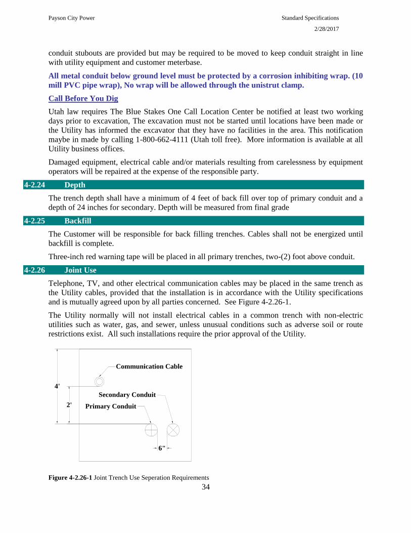
4-2.26 Joint Use
Telephone, TV, and other electrical communication cables may be placed in the same trench as
the Utility cables, provided that the installation is in accordance with the Utility specifications
and is mutually agreed upon by all parties concerned. See Figure 4-2.26-1.
The Utility normally will not install electrical cables in a common trench with non-electric
utilities such as water, gas, and sewer, unless unusual conditions such as adverse soil or route
restrictions exist. All such installations require the prior approval of the Utility.
Figure 4-2.26-1 Joint Trench Use Seperation Requirements
4'
2'
6"
Communication Cable
Primary Conduit
Secondary Conduit
Payson City Power Standard Specifications
2/28/2017
35
Communication conduits must be secured every 15 feet to keep separation during back
filling.
Communication conduits for Utopia must be Orange Electrical Conduit.
4-2.27 Conduits
The Utility requires the use of conduit for all underground service installations. Rigid
galvanized steel, IMC and gray electrical grade PVC schedule 40 (underground only) conduits
are acceptable materials for conduits installed by the Customer. Generally conduits are installed
in property fronts. All PVC Duct network must be inspected before back filling.
The following procedure for making cemented conduit joints will be used to join PVC to PVC
Cut the conduit square and remove all burrs from both the inside and outside with a
file or knife.
Remove dirt, grease and moisture from the end of the conduit and inside the coupling.
Test fit the conduit into the coupling. It should penetrate easily 1/4 to 3/4 of the way.
End Bell Couplings required to be placed at the end of conduit
CAUTION: Cement that is jelly-like or that has not been used within one year of the date
stamped on the can, should be replaced, and not used.
Apply an even layer of cement to the conduit and inside the coupling. A second layer
should be applied to the conduit if necessary to completely fill the gap.
Assemble the joint immediately while the cement is still soft and wet. Forcefully
bottom the conduit into the coupling. Turn the pipe or fitting during (but not after)
assembly to distribute the cement evenly. Hold in position for 30 seconds. Wipe off
excess cement.
Allow 15 minutes setting time for good handling strength. The joint will be
completely set within 24 hours.
Conduit must be approved by the Utility before installation. All 90-degree bends must be
minimum 36 inch radius. All conduits must contain a suitable non-conductive pull line (2500 lbs
mule tape.). All conduits shall be terminated at the open end with plastic bushings. Conduit sizes
must be approved by the Utility.
When the conduit terminates at the Utility pole, consult the Utility for exact conduit location.
For a utility service lateral, the top of the conduit is to be a minimum of 24 inches below
finished grade.
Stub-outs must be put at all transformers and splice box locations for future hookups. Stubouts
must be at least 3 feet from transformers and splice boxes.
All metal conduits below ground level must be protected by a corrosion inhibiting wrap.
4-2.28 Clearances From Swimming Pools
Follow National Electrical Safety Code.

Payson City Power Standard Specifications
2/28/2017
36
4-2.29 Underground Service To Residential, subdivisions
Underground services are provided under terms and condition detailed in Chapter 13 of Payson
Cities Ordinances.
High voltage distribution systems in subdivisions will be loop connected where advantageous and
be connected in a balanced three phase network if practical as determined by the Power and Light
Director.
All high voltage distribution systems in subdivisions and mobile home parks will be installed
according to design and layout prepared by an Electrical Engineer and Payson Power and Light. An
as-built map of the power net work must be submitted to the department of Power and Light after
installation. All changes must be pre-approved.
As per the Title 20 Subdivision Ordinance, all costs incurred, including labor and material, will be
paid by the developer. The City will terminate primary connections and will pull any underground
primary wire. The City will perform all work done on overhead energized conductors and the
Contractor will pay all costs associated with any line extensions involving live primary wires.
Material and labor charges are to be paid prior to ordering of high voltage wire, connectors, and
transformers. All secondary wire system will need to be bonded prior to installation.
The Developer or subcontractor can install the secondary system; however they must be licensed
with the city prior to beginning construction. All installations must be inspected and approved prior
to burial of underground systems Costs incurred as a result of a grade change or transformer
realignment shall be born by the subdivider/developer.
Individual residences within the subdivision will be responsible to trench, back fill, and install 600
Volt URD triplex cable in a PVC (sch 40) Duct from the secondary splice box or transformer to the
meter main disconnect(rigid pipe and 36 inch sweep 90') according to the original design and
layout.
All street lighting in Subdivision and Mobile Home parks shall be installed by the subdivider
according to city specifications. After city final inspection of lighting system Payson City will
assume ownership and will maintain said system.
Monolithic Curb Gutter and Sidewalk
Street
Back of Walk
Properity Line
PL
See Note 1
Servi
ce L
ater
al to
Met
er
Servi
ce L
ater
al to
Met
er
Handhole
Curb, Gutter, Planter and Sidewalk
Street
Front of Walk
Properity Line
PL
See Note 1
Servi
ce L
ater
al to
Met
er
Servi
ce L
ater
al to
Met
er
Handhole
Payson City Power Standard Specifications
2/28/2017
37
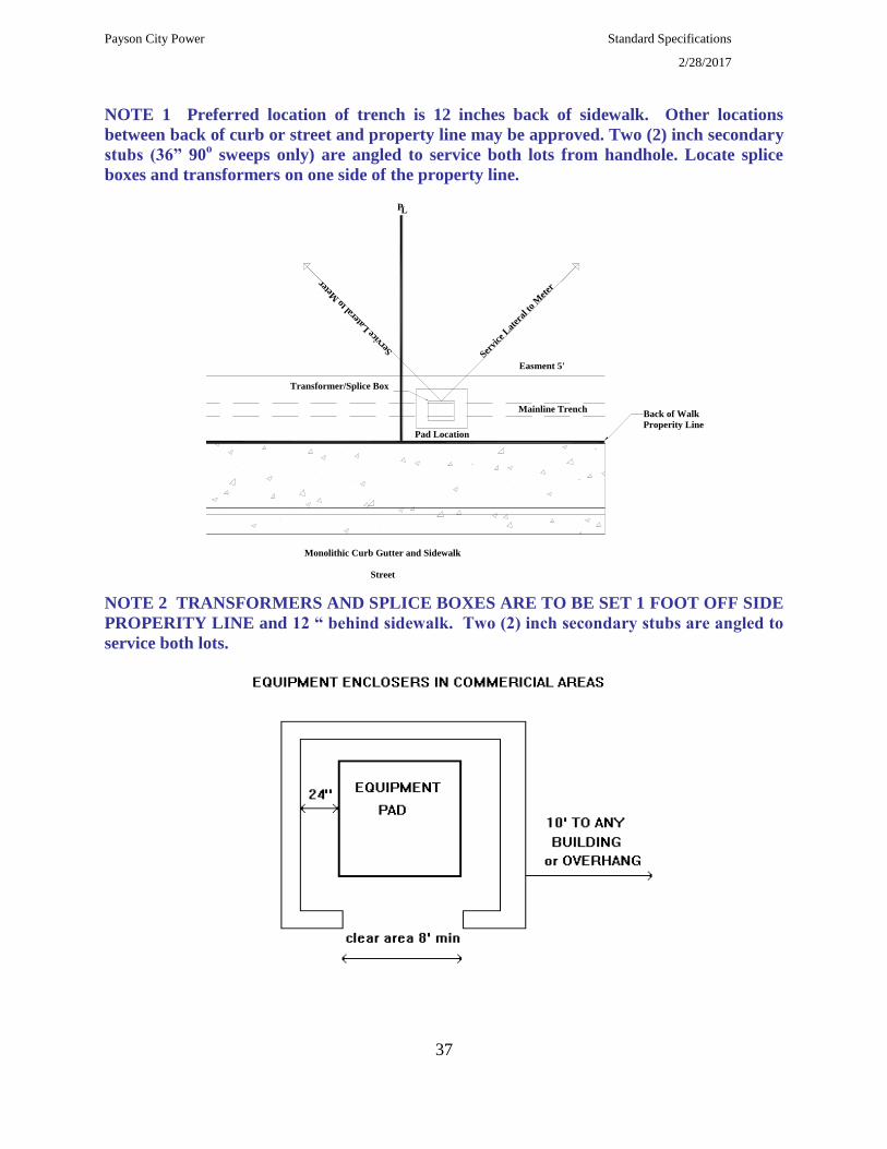
NOTE 1 Preferred location of trench is 12 inches back of sidewalk. Other locations
between back of curb or street and property line may be approved. Two (2) inch secondary
stubs (36” 90o sweeps only) are angled to service both lots from handhole. Locate splice
boxes and transformers on one side of the property line.
NOTE 2 TRANSFORMERS AND SPLICE BOXES ARE TO BE SET 1 FOOT OFF SIDE
PROPERITY LINE and 12 “ behind sidewalk. Two (2) inch secondary stubs are angled to
service both lots.
Monolithic Curb Gutter and Sidewalk
Street
Back of Walk
Properity Line
PL
Mainline Trench
Servi
ce L
ater
al to
Met
er
Servi
ce L
ater
al to
Met
er
Transformer/Splice Box
Pad Location
Easment 5'

Payson City Power Standard Specifications
2/28/2017
38
NOTE 3: CLEARANCES ARE ALSO REQUIRED FOR RESIDENTIAL EQUIPMENT
CUSTOMER FENCING OR OBSTRUCTIONS ADJACENT TO PROJECT
EQUIPMENT INSTALLATIONS
1. No building addition, building overhang or structure shall be built closer than 10
ft. horizontally from the edge of any equipment pad unless approved in writing
by the Utility.
2. There shall be no roof or covering over any pad-mounted equipment.
3. A gate the full width of the opening is permissible across the front or equipment. The
gate may be of solid material if a 6 inch clearance for ventilation is maintained between
bottom of gate and ground level. The gate is allowed to be lower than 6 inches if
constructed of mesh bar, louver or similar ventilating material. Gate must open at least
90 degrees for full opening width access and must be free of locks which would inhibit
access by utility personnel. Any gate must be furnished by customer.
4. Obstructions, including but not limited to, fences, trees, shrubs, or other similar large
vegetation and large rocks, shall NOT be permitted within 10 feet of the opening side
of equipment. The back and sides of all transformers and equipment require at least 18
inches of clearance from edge of the pad to any obstruction. For front or side lot
easements, the clearance to the back of pad-mounted equipment is defined by the
easement line.
5. Hinged gate(s), when open, may not block the exit route. When gate(s) is in the
maximum open position, the exit shall allow a 24 inch wide minimum opening, a
minimum of 6 feet from the equipment pad.
6. When equipment enclosures are constructed in commercial areas, the exit route shall be
directly away from the opening side of the pad-mounted equipment
P 1 P2 S1 S2 S3 S4
NOTE 4:
1. Connect ground rod to transformer ground lugs with a minimum of # 6 copper wire.
2. Top of ground rod and all conduits are to be 4” above final grade.
Payson City Power Standard Specifications
2/28/2017
39
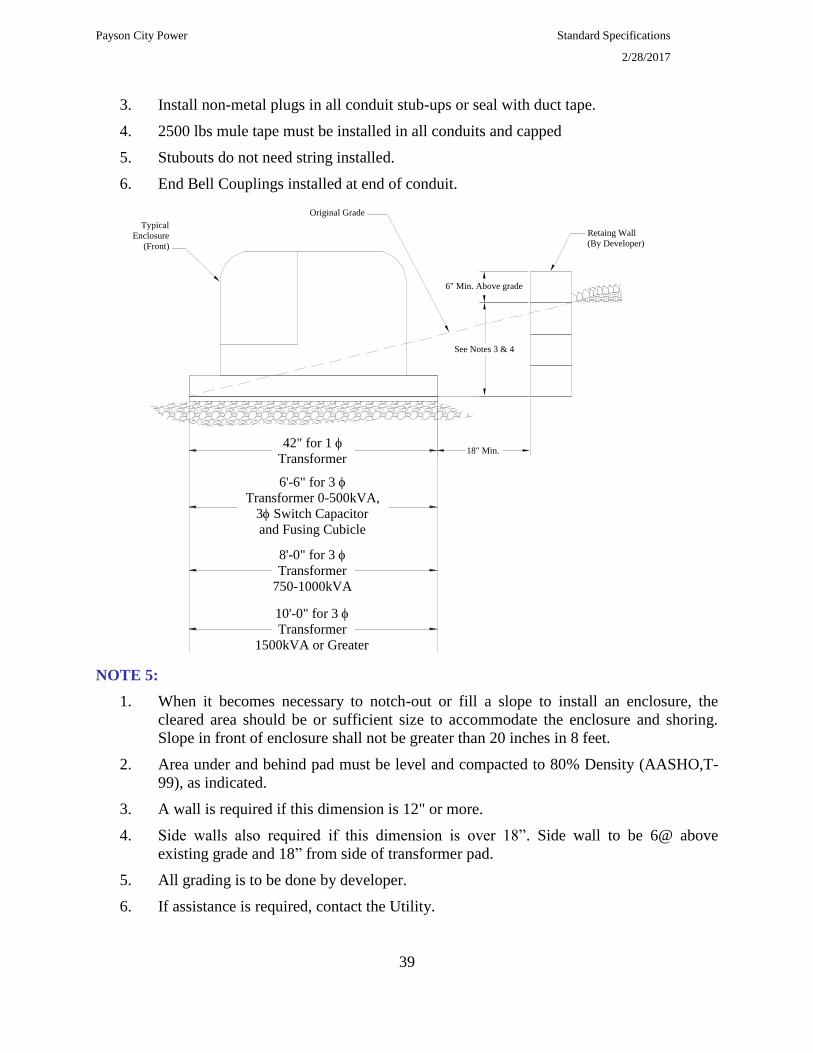
3. Install non-metal plugs in all conduit stub-ups or seal with duct tape.
4. 2500 lbs mule tape must be installed in all conduits and capped
5. Stubouts do not need string installed.
6. End Bell Couplings installed at end of conduit.
NOTE 5:
1. When it becomes necessary to notch-out or fill a slope to install an enclosure, the
cleared area should be or sufficient size to accommodate the enclosure and shoring.
Slope in front of enclosure shall not be greater than 20 inches in 8 feet.
2. Area under and behind pad must be level and compacted to 80% Density (AASHO,T-
99), as indicated.
3. A wall is required if this dimension is 12" or more.
4. Side walls also required if this dimension is over 18”. Side wall to be 6@ above
existing grade and 18” from side of transformer pad.
5. All grading is to be done by developer.
6. If assistance is required, contact the Utility.
42" for 1
Transformer
6'-6" for 3
Transformer 0-500kVA,
3 Switch Capacitor
and Fusing Cubicle
8'-0" for 3
Transformer
750-1000kVA
10'-0" for 3
Transformer
1500kVA or Greater
6" Min. Above grade
See Notes 3 & 4
18" Min.
Retaing Wall
(By Developer)
Original Grade
Typical
Enclosure
(Front)

Payson City Power Standard Specifications
2/28/2017
40
4-2.30 Nonresidential Underground Service
For underground service to commercial or industrial buildings or projects, the Customer or
developer is responsible for all trenching, back filling, conduit, wire terminators, pulling and
terminating secondary wire, meters and transformer pads or vaults within the project.
Where a padmounted transformer, current transformer enclosure, or other equipment are
installed in a location where it might be struck by a motorized vehicle, the Customer is to install
Utility-approved barrier posts to protect this equipment.
Primary cables will be installed by the Utility in Customer provided conduit. The Utility will
install the conduit up the pole. The Utility will designate the proper position on the pole for the
conduct prior to the contractor installation of the 90-degree bend and 10 foot of Rigid or IMC at
the base of the pole
All conduits shall be capped at both ends at the time of installation to keep free of dirt and debris.
4-2.31 Service at Primary Voltage General
The Utility will provide primary voltage delivery to qualified Customers without transformation,
from the high-voltage or primary" distribution system under terms and conditions set forth in
which provide that: (1) The distribution system's nominal voltage is used; (2) Service at primary
voltage will not, in the Utility's judgment, adversely affect the operation of the Utility's
distribution System or service to other Customers; and (3) Such service Can be supplied in a safe
and reliable manner. All Customers requesting service at a primary voltage must agree to those
special requirements that the Utility may from time to time establish as necessary,
4-2.32 Customer Equipment
The Customer receiving service at primary or higher Voltage shall own and maintain poles,
conductors, cables, transformers and associated protective devices in accordance with the current
filed Electric Service Regulations and tariff or special contract. All such equipment, its
arrangement, and its operation will be subject to Utility approval. Except by prior written
approval of the Utility, three-phase transformers connected to primary voltage lines are to be in
conformance with the utility's transformer specification.
The customer will provide a disconnecting means, such as Option I or Option 2 as shown below,
at the point of delivery, to disconnect the customers system-from the Utility's system. Utility
must approve disconnecting means prior to installation.

Payson City Power Standard Specifications
2/28/2017
41
To assure timely restoration of service in case of failure, all primary voltage Customer owned
wiring and equipment, including transformers and associated protective devices, should be the
same types and have the same characteristics as those used by the Utility. The arrangement and
operation of such equipment will be subject to the utilities approval.
4-2.33 Utility Equipment
The Utility will normally provide at Customer expense the pole or a padmounted enclosure,
containing the primary metering equipment. The point of interconnection, or the padmounted
primary metering enclosure when the service is underground, shall be designated as the point of
delivery.
4-2.34 Painting of Utility Equipment
NOTES:
Payson City Power Standard Specifications
2/28/2017
42
1. At the customers request and expense, the customer may paint pad mounted equipment such
as transformers, switching and fusing cubicles, and capacitor enclosures. Substation fences or
other equipment are not allowed to be painted by the customer. The customer must notify
the district prior to painting utility equipment by calling 465-5270.
2. All identifying lettering, numbering, warning signs, handles, locks and pads will not be
painted over
3. The utility retains the right to charge customers full cost of restoring its equipment to
acceptable condition (repainting to original utility color) if:
The customer fails to comply with these requirements.
The painting done by the customer on utility equipment is not maintained by the customer.
4. Color choices used by the customer shall be complimentary to the surroundings of the
equipment. It is recommended that to prevent conflicts, color acceptance should be obtained
from the utility prior to painting.
5. If for any reason, the utility has to replace a piece of pad mounted equipment that has been
painted by a customer, the new equipment will be standard utility color - if the customer
wants to paint and change the color of the equipment after replacement, they may do so (see
note 1).
6. Preparation of utility equipment is limited to cleaning the surface using a detergent and
water. No sanding or chemicals solvents are to be used on the painted surface of the
equipment.
4-2.35 4-2.35 Padmount Transformer specifications
Padmounted Transformers must be new and constructed and tested in accordance with ANSI
C57.12.25 and ANSI C 57.12.00 latest revisions. All transformers must meet Western
Underground Committee Tamper Proof Guide 2.13; coils must be wound with thermally
activated, epoxy coated paper. Transformers must meet EEI Finishing Guidelines latest
revisions, finishing certification must be submitted. All transformers must be designed to pass
short circuit test in accordance with ANSI Publication C57.12.00 latest revisions. All
transformers must be 5 inches above final grade.
Must be Oil filled, NON-PCB, less than 1 PPM dead front, loop feed, externally replaceable
bayonet fuse with load sensing link, bayonet drip shield, 2 high voltage wells with bushing
inserts, automatic pressure relief device, three all purpose low voltage studs 5/8” in diameter.
95 KV BIL high voltage, 30 KV BIL low voltage, 65° C temperature rise, door to swing from
front of transformer.
The guaranteed estimated average no load and full load losses must be based on a base cost
evaluated cost at $ 5.00 per watt for no load losses and $ 2.00 per watt for full load losses.
Actual loss test results on transformer must be supplied at the time of delivery.
Single Phase transformer sleeve size will be at least 42” X 42” for transformers without fins 60”
X 42” with fins with an opening of 12” X 24” with 2 unistrut clamps, spring nuts, and bar or
equivalent. Must be R.E.A. approved.
Two Bronze grounding connectors Fargo GC-207 or equivalent.
Payson City Power Standard Specifications
2/28/2017
43
Transformer secondary bus connectors shall be insulated on the phases and equipped with 6
positions. Connectors shall have pre-applied oxide inhibitor. Connectors must meet or exceed
ANSI C119.4-1991 and C119.1-1986; example: CONNECTOR MANUFACTURING CO. Cat
# NSC350-6I. Must except wire size # 10 AWG to 350 MCM.
4-2.36 Street Light Specifications
All street lighting in Subdivision shall be installed by the subdivider. Type of street light to be
determined by utitliy. Street lights will be of cobra head style or lamp post style. Cobra head shall
be fitted with a trigger latch for no tool opening of the fixture for installation and service. Shall
be equipped with separate power pad, drop down door with quick connect or disconnect electric
plug. Shall be equipped with a instant on, 1800 Watt Photo Cell. All lamp wattage will be 100
Watt HPS or Metal Halide unless specified by the Utility. An Acrylic type lens cover will be
used with refractor to push all light down to the ground.
Ordering data: 120 Volt, Regulated Ballast, High Power Factor, Standard Distribution Pattern
type II.
Pole shall be manufactured for the purpose of lighting and be corrosion resistant with a minimum
light height of 20’ above ground level Light pole will have at least a 6 foot arm if cobra head is
used. A pole height of 14’ above ground shall be used if lamp post type. Shall be equipped with
a service and inspection opening with cover 12” to 24” above ground level
4-2.37 Splice Box and Connector Specification
Connectors will meet or exceed ANSI C119.4-1991 and C119.1-1986. Must except wire size
#12 AWG to 350 MCM. Secondary underground junction connectors must all be insulated and
water proof and equipped with the number of positions suitable for location of connectors. They
will have pre-applied oxide inhibitor, with silicone grease on all rubber joints. EXAMPLE:
CONNECTOR MANUFACTURE CO. Cat. # SSBC 350-6LI.
Splice box shall be a minimum of 16” X 25” X 15” with bolt down lid. EXAMPLE: Carson
industries Model 1324CP-12L.
4-2.38 Sectionalizing Enclosures Specifications
Single Phase Sectionalizing Enclosures:
Shall accommodate at least a 4 position dead front bus or greater if specified by Utility.
Constructed of a minimum of 12 gauge steel.
Must have at least 1 parking bushings.
Door latching shall meet or exceed ANSI C57.12.28-1988 and fitted with penta head stainless
steed bolt recessed below Padlocking provisions.
Shall be constructed to accommodate a fiberglass boot that will be supplied with sectionalizer by
contractor.
Three Phase Sectionalizing Enclosures:
Shall accommodate at least three, 4 position dead front bus or greater if specified by Utility.
Constructed of a minimum of 12 gauge steel.

Payson City Power Standard Specifications
2/28/2017
44
Must have at least 3 parking bushings.
Door latching shall meet or exceed ANSI C57.12.28-1988 and fitted with penta head stainless
steed bolt recessed below Padlocking provisions.
Shall be constructed to accommodate a fiberglass boot that will be supplied with sectionalizer by
contractor.
Payson City Power Standard Specifications
2/28/2017
45
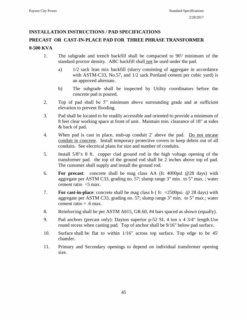
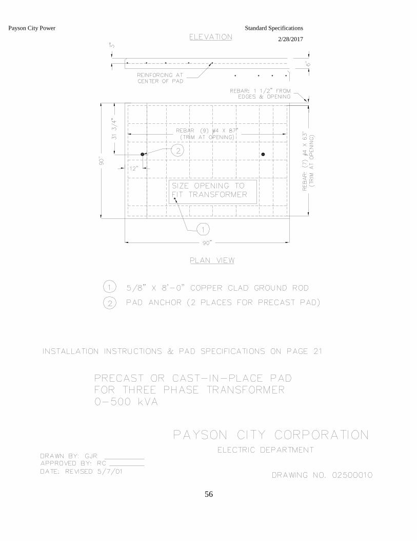
INSTALLATION INSTRUCTIONS / PAD SPECIFICATIONS
PRECAST OR CAST-IN-PLACE PAD FOR THREE PHRASE TRANSFORMER
0-500 KVA
1. The subgrade and trench backfill shall be compacted to 90'/ minimum of the
standard proctor density. ABC backfill shall not be used under the pad.
a) 1/2 sack lean mix backfill (slurry consisting of aggregate in accordance
with ASTM-C33, No.57, and 1/2 sack Portland cement per cubic yard) is
an approved alternate.
b) The subgrade shall be inspected by Utility coordinators before the
concrete pad is poured.
2. Top of pad shall be 5” minimum above surrounding grade and at sufficient
elevation to prevent flooding.
3. Pad shall be located to be readily accessible and oriented to provide a minimum of
8 feet clear working space at front of unit. Maintain min. clearance of 18" at sides
& back of pad.
4. When pad is cast in place, stub-up conduit 2' above the pad. Do not encase
conduit in concrete. Install temporary protective covers to keep debris out of all
conduits. See electrical plans for size and number of conduits.
5. Install 5/8"x 8 ft. copper clad ground rod in the high voltage opening of the
transformer pad. the top of the ground rod shall be 2 inches above top of pad.
The customer shall supply and install the ground rod.
6. For precast: concrete shall be mag class AA (fc 4000psl @28 days) with
aggregate per ASTM C33, grading no. 57; slump range 3" min. to 5" max. ; water
cement ratio =5 max.
7. For cast-in-place: concrete shall be mag class b ( fc =2500psi @ 28 days) with
aggregate per ASTM C33, grading no. 57; slump range 3" min. to 5" max.; water
cement ratio = .6 max.
8. Reinforcing shall be per ASTM A615, GR.60, #4 bars spaced as shown (equally).
9. Pad anchors (precast only): Dayton superior p-52 SL 4 ton x 4 3/4" length.Use
round recess when casting pad. Top of anchor shall be 9/16" below pad surface.
10. Surface shall be flat to within 1/16" across top surface. Top edge to be 45'
chamfer.
11. Primary and Secondary openings to depend on individual transformer opening
size.

Payson City Power Standard Specifications
2/28/2017
46
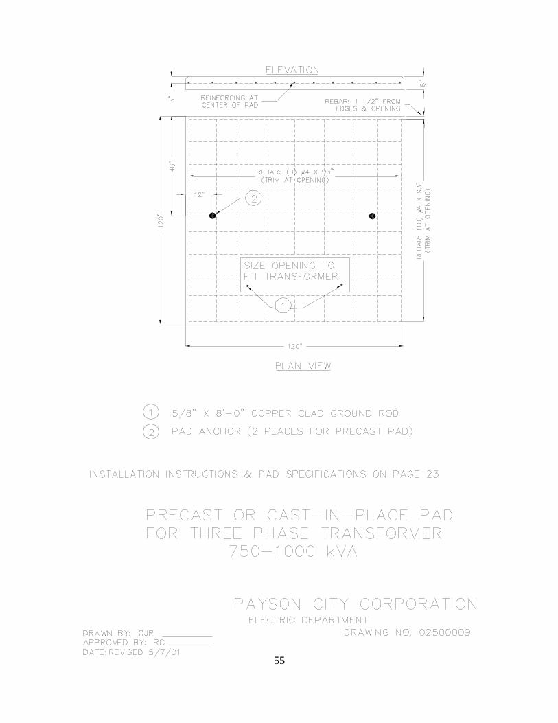
INSTALLATION INSTRUCTIONS / PAD SPECIFICATIONS
PRECAST OR CAST-IN-PLACE PAD FOR THREE PHRASE TRANSFORMER
INSTALLATION
750-1000 KVA
1. The subgrade and trench backfill shall be compacted to 90'/ minimum of the standard
proctor density. ABC backfill shall not be used under the pad.
2. 1/2 sack lean mix backfill (slurry consisting of aggregate in accordance with ASTM-
C33, No.57, and 1/2 sack Portland cement per cubic yard) is an approved alternate.
3. The subgrade shall be inspected by Utility coordinators before the concrete pad is poured.
4. Top of pad shall be 4” minimum above surrounding grade and at sufficient elevation to
prevent flooding.
5. Pad shall be located to be readily accessible and oriented to provide a minimum of 8 feet
clear working space at front of unit. Maintain min. clearance of 18" at sides & back of
pad.
6. When pad is cast in place, stub-up conduit 2” above the pad. Do not encase conduit in
concrete. Install temporary protective covers to keep debris out of all conduits. See
electrical plans for size and number of conduits.
7. Install 5/8"x 8 ft. copper clad ground rod in the high voltage opening of the transformer
pad. The top of the ground rod shall be 2 inches above top of pad.
8. For precast: concrete shall be mag class AA (fc = 4000psl @28 days) with aggregate per
ASTM C33, grading no. 57; slump range 3" min. to 5" max. ; water cement ratio =5
max.
9. For cast-in-place: concrete shall be mag class b ( fc = 4000psi @ 28 days) with
aggregate per ASTM C33, grading no. 57; slump range 3" min. to 5" max.; water
cement ratio = .6 max.
10. Reinforcing shall be per ASTM A615, GR.60, #4 bars spaced as shown (equally).
11. Pad anchors (precast only): Dayton superior p-52 SL 4 ton x 4 3/4" length. Use round
recess when casting pad. Top of anchor shall be 9/16" below pad surface.
12. Surface shall be flat to within 1/16” across top surface. Top edge to be 45’ chamfer.
13. Primary and Secondary openings to depend on individual transformer opening size.

Payson City Power Standard Specifications
2/28/2017
47
INSTALLATION INSTRUCTIONS & PAD SPECIFICATIONS
CAST-IN-PLACE PAD
FOR THREE PHASE TRANSFORMER
1500-2500 kVA
1. The subgrade and trench backfill shall be compacted to 90'/ minimum of the standard
proctor density. ABC backfill shall not be used under the pad.
2. 1/2 sack lean mix backfill (slurry consisting of aggregate in accordance with ASTM-C33,
No.57, and 1/2 sack Portland cement per cubic yard is an approved alternate.
3. The subgrade shall be inspected by Utility coordinators before the concrete pad is poured.
4. Top of pad shall be 4' minimum above surrounding grade and at sufficient elevation to
prevent flooding.
5. Pad shall be located to be readily accessible and oriented to provide a minimum of 8 feet
clear working space at front of unit. Maintain min. clearance of 18" at sides & back of
pad.
6. When pad is cast in place, stub-up conduit 2” above the pad. Do not encase conduit in
concrete. Install temporary protective covers to keep debris out of all conduits. See
electrical plans for size and number of conduits.
7. Install 2 5/8"x 8 ft. copper clad ground rod in the high voltage opening of the
transformer pad. the top of the ground rod shall be 2 inches above top of pad.
8. Concrete shall be mag class B (fc = 4000 psi @28 days) with aggregate per ASTM C33,
grading No. 57; slump range 3" min. to 5" max. ; water cement ratio = . 6 max.
9. Reinforcing shall be per ASTM A615, GR.60, #4 bars spaced as shown (equally).
10. Surface shall be flat to within 1/16" across top surface. Top edge to be 45' chamfer.
11. Primary and Secondary openings to depend on individual transformer opening size.

48

Payson City Power Standard Specifications
2/28/2017
49

Payson City Power Standard Specifications
2/28/2017
50

Payson City Power Standard Specifications
2/28/2017
51
Payson City Power Standard Specifications
2/28/2017
52

Payson City Power Standard Specifications
2/28/2017
53
Payson City Power Standard Specifications
2/28/2017
54
55
Payson City Power Standard Specifications
2/28/2017
56

Payson City Power Standard Specifications
2/28/2017
57

Payson City Power Standard Specifications
2/28/2017
58
SECTION A-ASECTION A-A
PLAN VIEWPLAN VIEW
11 10' OF 40 BARE COPPER FOR GROUNDING, CITY WILL INSTALL10' OF 40 BARE COPPER FOR GROUNDING, CITY WILL INSTALL
LONG SIDE OF BOX TO PARALLEL SIDEWALKLONG SIDE OF BOX TO PARALLEL SIDEWALK
PAD SWITCH SLEEVEPAD SWITCH SLEEVE
PAYSON CITY CORPORATIONPAYSON CITY CORPORATIONELECTRIC DEPARTMENTELECTRIC DEPARTMENT
DRAWING NO. 02500012DRAWING NO. 02500012
DRAWN BY: CJEAPPROVED BY: RC
DATE: REVISED 2/07/05
DRAWN BY: CJEAPPROVED BY: RC
DATE: REVISED 2/07/05
8" TO FINISH GRADE8" TO FINISH GRADE8" TO FINISH GRADE
4" EXPOSED4" EXPOSED
36"36"36"
36" SWEEP 9036" SWEEP 90 GROUND RODSGROUND RODS
5/8" X 8'-0" COPPER
CLAD GROUND ROD
5/8" X 8'-0" COPPER
CLAD GROUND ROD
12" MIN12" MIN
1' MIN BOW1' MIN BOW
BACK OF WALKBACK OF WALK
22
AA