PAVEMENT DESIGN Using Geosynthetic Karnala Bpcl
9
1 1.0 INTRODUCTION M/s. Bharat Petroleum Chemicals Private Ltd. plans construc tion of dr iveway at NRO Karnal a, Virar, Dist.:- Palghar. Dr. Ganesh S. Kame was appointed to review soil report and design the driveway. This report includes the design considerations engineering recommendations for the proposed driveway. 2.0 DESIGN OF DRIVEWAY Judging from sides of the trial pit excavations, subsurface profile at the site consists of residual soils overlying stiff silty sand. Groundwater table was not encountered at a depth of approximately 1.5 m in the trial pit. As mentioned in the report, stiff silty clay was encountered at a depth more than 0.5 m below ground surface at this site. Maximum net allowable soil bearing pressure of 10 t/m 2 is permitted for the development. Based on the performance of existing designs and using analytical approach, IRC offers simple design charts and a catalogue of pavement designs (Fig. 1). The pavement designs are given for subgrade CBR values ranging from 2 per cent to 10 per cent and design traffic ranging from 1 msa to 150 msa for an average annual pavement temperature of 35°C. In this report similar approach is adopted for construction of driveway. A typical WBM is shown in Fig. 2. Fig. 1 Pavement Thickness as per IRC 37:2012
-
Upload
drganesh-kame -
Category
Documents
-
view
218 -
download
0
Transcript of PAVEMENT DESIGN Using Geosynthetic Karnala Bpcl

8/16/2019 PAVEMENT DESIGN Using Geosynthetic Karnala Bpcl
http://slidepdf.com/reader/full/pavement-design-using-geosynthetic-karnala-bpcl 1/9
1
1.0 INTRODUCTION
M/s. Bharat Petroleum Chemicals Private Ltd. plans construction of driveway at NRO Karnala,
Virar, Dist.:- Palghar. Dr. Ganesh S. Kame was appointed to review soil report and design the
driveway. This report includes the design considerations engineering recommendations for the
proposed driveway.
2.0 DESIGN OF DRIVEWAY
Judging from sides of the trial pit excavations, subsurface profile at the site consists of residual
soils overlying stiff silty sand. Groundwater table was not encountered at a depth of approximately
1.5 m in the trial pit. As mentioned in the report, stiff silty clay was encountered at a depth more
than 0.5 m below ground surface at this site. Maximum net allowable soil bearing pressure of
10 t/m2is permitted for the development.
Based on the performance of existing designs and using analytical approach, IRC offers
simple design charts and a catalogue of pavement designs (Fig. 1). The pavement designs
are given for subgrade CBR values ranging from 2 per cent to 10 per cent and design traffic
ranging from 1 msa to 150 msa for an average annual pavement temperature of 35°C.
In this report similar approach is adopted for construction of driveway. A typical WBM is
shown in Fig. 2.
Fig. 1 Pavement Thickness as per IRC 37:2012

8/16/2019 PAVEMENT DESIGN Using Geosynthetic Karnala Bpcl
http://slidepdf.com/reader/full/pavement-design-using-geosynthetic-karnala-bpcl 2/9
2
Fig. 2 Typical WBM
Based on existing soil condition at site and the IRC recommendation the value of CBR canadopted between 3-5. Table 1 gives typical values as per IRC.
Table 1 Some Typical values
Classification CBR MR (psi) Typical Description
Good ≥ 10 20,000 Gravels crushed stone and sandy soils. GW,
GP, GM, SW, SP, SM soils are often in this
category
Fair 5 - 9 10,000 Clayey gravel and clayey sand, fine silt soils.
GM, GC, SM, SC soils are often in this
category.
Poor 3 - 5 5,000 Fine silty sands, clays, silts, organic soils.
CH, ML, MH, CM, OL, OH soils are often in
this category
3.0 WORKED-OUT EXAMPLES ILLUSTRATING THE DESIGN METHOD
3.1 Bituminous Pavements with Untreated Granular Layer
Design the pavement for construction of a new flexible pavement with the following data:
Bituminous layer
Granular Base
Granular Sub-base
Subgrade
Treated asGranular Layer
Bituminous Surfaceing with
Granular Base and Granular Sub-base

8/16/2019 PAVEMENT DESIGN Using Geosynthetic Karnala Bpcl
http://slidepdf.com/reader/full/pavement-design-using-geosynthetic-karnala-bpcl 3/9
3
DATA
(i) Four lane divided carriageway
(ii) Initial traffic in the year of completion of construction = 5000 CV/day
(Sum of both directions)
(iii) Percentage of Single, Tandem and Tridem axles are 45 per cent, 45 per cent and 10 per
cent respectively
(iv) Traffic growth rate per annum = 6.0 per cent
(v) Design life = 20 years
(vi) Vehicle damage factor = 5.2
(Based on axle load survey)
(vii) CBR of soil below the 500 mm of the subgrade = 3 per cent
(viii) CBR of the 500 mm of the subgrade from borrow pits = 10 per cent
DESIGN CALCULATIONS
(i) Lane Distribution factor = 0.75
(ii) Initial traffic = 2500 CVPD assuming 50 per cent in each direction.
(iii) Vehicle Damage Factor (VDF) computed for the traffic = 5.2.
(iv) Cumulative number of standard axles to be catered for in the design
N =
2500 x 365 x[(1 + 0.06)20-1]
x 0.75x5.2 = 131msa0.06
(v) CBR of the embankment material = 3 per cent,
CBR of 500 mm of subgrade = 10 per cent,
Effective CBR of the subgrade from (IRC) = 7 per cent
8/16/2019 PAVEMENT DESIGN Using Geosynthetic Karnala Bpcl
http://slidepdf.com/reader/full/pavement-design-using-geosynthetic-karnala-bpcl 4/9
4
Design resilient modulus of the compacted subgrade = 17.6(7)0.64
= 62 MPa
(vi) Thickness of granular layers: WMM = 250 mm, GSB = 230 mm
Resilient modulus of granular layer = 0.2 x (480)° 45 x 62 = 200 MPa.
The upper 100 mm of the cemented sub-base should be open graded so that its permeability
is about 300 mm/day or higher for quick removal of water entering from the surface.
4.0 GEOSYNTHETICS FOR CONSTRUCTION ROADS
Geosynthetic system solutions are used in the construction of roadways and trafficked areas.
The coarse grained cover soil interlocks with the Geogrid (grid apertures ≥ 28 mm) creating a
bond. This immediate interlock provides a horizontal force transfer which increases the bearing
capacity of the soil due to the high force absorption with low elongation. The required bearing
capacity can be achieved without additional expensive soil exchange, and in some cases, the base
course thickness can be reduced.
5.0 FINAL DESIGN USING GEOGRID
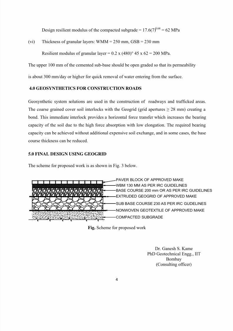
The scheme for proposed work is as shown in Fig. 3 below.
Fig. Scheme for proposed work
Dr. Ganesh S. Kame
PhD Geotechnical Engg., IIT
Bombay
(Consulting officer)
WBM 130 MM AS PER IRC GUIDELINES
SUB BASE COURSE 230 AS PER IRC GUDELINES
COMPACTED SUBGRADE
PAVER BLOCK OF APPROVED MAKE
EXTRUDED GEOGRID OF APPROVED MAKE
NONWOVEN GEOTEXTILE OF APPROVED MAKE
BASE COURSE 200 mm OR AS PER IRC GUIDELINES

8/16/2019 PAVEMENT DESIGN Using Geosynthetic Karnala Bpcl
http://slidepdf.com/reader/full/pavement-design-using-geosynthetic-karnala-bpcl 5/9
5
Table 2 Details for WBM as per IRC 19:2005
6.0 WATER BOUND MACADAM SUB BASE/BASE COURSE
The sub-base course shall consist of one or more layers, each or 100 mm compacted thickness.
The base course shall consist of one or more layers, each of 75 mm compacted thickness.
6.1 Stone Aggregate for WBM
The coarse aggregate shall be hard, crushed or broken stone metal from quarries approved by
Engineer-In Charge, it shall be hard durable and free from flat elongated, Soft and disintegrated
particles. It shall not have excess of dirt and other objectionable matter. The quality, size, and
grading of the coarse aggregate shall be conforming to IRC 19: STD Spec and code of practice
for WBM.
6.1.1 Grading of the coarse aggregate for the sub-base course
The grading of the coarse aggregate for the sub-base course shall be as follows:

8/16/2019 PAVEMENT DESIGN Using Geosynthetic Karnala Bpcl
http://slidepdf.com/reader/full/pavement-design-using-geosynthetic-karnala-bpcl 6/9
6
6.1.2 Grading of the coarse aggregate for the base course
The grading of the coarse aggregate for the base course shall be as follow:
6.1.3 Physical requirement of coarse aggregates for sub-base course
Physical requirement of coarse aggregates for sub-base course shall be as below: i)Los Angles
Abrasion Value-60% (Maximum) Or ii)Aggregate Impact Value -50% (Maximum)
6.1.4 Physical requirement of coarse aggregates for base course
Physical requirement of coarse aggregates for base course shall be as below: i)Los Angles
Abrasion Value-50% (Maximum) Or Aggregate Impact Value- 40% (Maximum) ii) Flakiness
index value -15% (Maximum)
Samples of test shall be representative of the material to be used and collected as per IS: 2430.
7.0 WBM ROAD CONSTRUCTION PROCEDURE
WBM Stands for Water Bound Macadam which is the most commonly used road construction
procedure for over more than 190 years.Pioneered by Scottish Engineer John Loudon McAdam
around 1820 Macadam is a type of Road Construction. The broken stones of base and surface
course,if any are bound by the stone dust is presence of moisture is called WBM Roads.
Macadam means the pavement base course made of crushed or broken aggregate mechanically
interlocked by rolling and the voids filled with screening and binding material with the assistance
of water.WBM may be used as a sub-base,base or a surface course.The thickness of each
compacted layer of WBM ranges from 10cm to 7.5cm depending on size and the gradation
of aggregate used.

8/16/2019 PAVEMENT DESIGN Using Geosynthetic Karnala Bpcl
http://slidepdf.com/reader/full/pavement-design-using-geosynthetic-karnala-bpcl 7/9
7
7.1 Construction Procedure:
1.Prepare the foundation for receiving the WBM course.
2. Lateral confinement may be done by compacting the shoulder to advance, to a thickness equal
to that of the compacted WBM layer and by trimming the inner side vertically.
3. Spreading of Coarse Aggregate.
4.Compaction of coarse aggregate is done by wheeled power roller of capacity 6 to 10 tonnes or
alternately by an equivalent vibratory roller.

8/16/2019 PAVEMENT DESIGN Using Geosynthetic Karnala Bpcl
http://slidepdf.com/reader/full/pavement-design-using-geosynthetic-karnala-bpcl 8/9
8
5.Dry screening is applied gradually over the surface to fill the interstices in these.
6.The surface is sprinkled with water,swept and rolled.
7.Binding material is applied at a uniform and slow rate at two and more layers.
8.WBM Coarse is allowed to set overnight.

8/16/2019 PAVEMENT DESIGN Using Geosynthetic Karnala Bpcl
http://slidepdf.com/reader/full/pavement-design-using-geosynthetic-karnala-bpcl 9/9
9
8.0 REFERENCES
1) Foundation Analysis and Design, J.E. Bowles, McGraw Hill Publication, 5th Edition, 1996.
2) Soil Mechanics and Foundation Engineering, K.R. Arora, Standard Publishers Distributors,
Fourth Edition, 1997.
3) Soil Mechanics in Engineering Practice, 2nd
Edition, Terzaghi K. and Peck R. B., John Willey
and Sons, 1967.
4) IRC 27:2012
5) IRC 19:2005
6) Geosynthetic Design and Construction Guidelines, Publication No FHWA HI-95-038
http://www.fhwa.dot.gov/engineering/geotech/pubs/011431.pdf
6) http://www.dot.ca.gov/hq/maint/Pavement/Offices/Pavement_Engineering/PDF/Subgra
de_Enhancement_Geosynthetic_Guide_09212013.pdf
7) http://www.wsdot.wa.gov/publications/manuals/fulltext/M22-01/630.pdf
8) Design and Practice of Geosynthetic-Reinforced Soil Structures, Professor Dov Leshchinsky