Paul W. Brazis, Jr., PhD June 2018...limits LED operation to relatively low input power densities....
18
Laser diode lighting: the potential future of high-efficiency solid-state illumination Paul W. Brazis, Jr., PhD June 2018
Transcript of Paul W. Brazis, Jr., PhD June 2018...limits LED operation to relatively low input power densities....

Laser diode lighting: the potential future of high-efficiency solid-state illuminationPaul W. Brazis, Jr., PhDJune 2018

P A G E 2
L A S E R D I O D E L I G H T I N G: T H E P OT E N T I A L F UTU R E O F H I G H- E F F I C I E N CY S O L I D-STAT E I L LU M I N AT I O N
EXECUTIVE SUMMARY
For more than a century, incandescent bulbs have been the dominant technology for producing artificial light. Though the efficiency of modern incandescent bulbs has improved, other lighting technologies have been rapidly replacing them in most applications. Fluorescents and CFLs exhibit improvement in efficiency relative to incandescent lighting but, in recent years, have been supplanted by light emitting diode (LED) technologies. This is due to the superior energy efficiency, controllable light spectral output, instant-on performance, and longevity of LEDs.
Though LED lighting is increasingly dominating lighting applications, it has shortcomings. Early white LED lighting tended to be perceived as too bluish and harsh to the eye, though more recent “warm white” LEDs seem to have reduced this issue. However, white LED lighting still tends to emit relatively weakly at longer (i.e., redder) wavelengths, which is of particular concern in display technologies. LEDs also have significant performance limitations, primarily due to “efficiency droop,” which limits LED operation to relatively low input power densities. Increasing the amount of light produced per unit area of a solid-state lighting source (such as an LED) could potentially reduce unit cost since the chip size can be smaller for an equivalent amount of light output.
Blue laser diodes are one proposed technology. Laser diodes can, in principle, have high efficiencies at much higher input power densities than LEDs. Hence the replacement of blue LEDs with blue laser diodes has the potential to be the next evolutionary step in lighting technology. Their ability to achieve high output efficiencies at very high power densities (100 to 1000 times that of blue LEDs) enables considerably higher light output with much smaller die size. These high densities are of particular interest in automotive applications, such as high-intensity headlamps, and may lead to new means of delivering lighting to buildings using novel approaches as through fiber optic cabling and other waveguides.
Currently, commercial applications are limited by overall cost considerations and regulatory issues. The cost of laser lighting continues to be significantly higher than that for blue LEDs, though the higher power densities may allow for reduced cost of blue laser lighting as less die area is required for a given amount of light output. Use of laser lighting in automotive headlamps brings several advantages in beam distance and efficiency that are not achievable with other technologies. However, regulatory issues prevent many of these advantages from being included in production vehicles, especially within the United States. Therefore, regulatory changes are required before laser lighting can be introduced into the American market. Considering this obstacle and the fact that most automotive laser lighting work is being conducted with European manufacturers, it is likely that laser lighting will first enter the European market, with changes in American regulations to follow should the technology prove popular in Europe.
P A G E 3
L A S E R D I O D E L I G H T I N G: T H E P OT E N T I A L F UTU R E O F H I G H- E F F I C I E N CY S O L I D-STAT E I L LU M I N AT I O N
TABLE OF CONTENTS
Contents
Executive Summary . . . . . . . . . . . . . . . . . . . . . . . . . . . . . . . . . . . . . . . . . . . . . . . . . . . . . . . . . . . . . . . . . . . . . . . . . . . . . . . . . . . . . . . . . . . . . . . . . . . . . . . . . 2
Background . . . . . . . . . . . . . . . . . . . . . . . . . . . . . . . . . . . . . . . . . . . . . . . . . . . . . . . . . . . . . . . . . . . . . . . . . . . . . . . . . . . . . . . . . . . . . . . . . . . . . . . . . . . . . . . . . 4
Theory . . . . . . . . . . . . . . . . . . . . . . . . . . . . . . . . . . . . . . . . . . . . . . . . . . . . . . . . . . . . . . . . . . . . . . . . . . . . . . . . . . . . . . . . . . . . . . . . . . . . . . . . . . . . . . . . . . . . . . 6
LED Operation and Spontaneous Emission . . . . . . . . . . . . . . . . . . . . . . . . . . . . . . . . . . . . . . . . . . . . . . . . . . . . . . . . . . . . . . . . . . . . . . . . . . . . . . . . . . 6
Stimulated Emission . . . . . . . . . . . . . . . . . . . . . . . . . . . . . . . . . . . . . . . . . . . . . . . . . . . . . . . . . . . . . . . . . . . . . . . . . . . . . . . . . . . . . . . . . . . . . . . . . . . . . . . . 8
Population Inversion . . . . . . . . . . . . . . . . . . . . . . . . . . . . . . . . . . . . . . . . . . . . . . . . . . . . . . . . . . . . . . . . . . . . . . . . . . . . . . . . . . . . . . . . . . . . . . . . . . . . . . .11
Physical Structure of a Laser Diode . . . . . . . . . . . . . . . . . . . . . . . . . . . . . . . . . . . . . . . . . . . . . . . . . . . . . . . . . . . . . . . . . . . . . . . . . . . . . . . . . . . . . . . . .12
Performance Comparisons . . . . . . . . . . . . . . . . . . . . . . . . . . . . . . . . . . . . . . . . . . . . . . . . . . . . . . . . . . . . . . . . . . . . . . . . . . . . . . . . . . . . . . . . . . . . . . . . .14
Applications . . . . . . . . . . . . . . . . . . . . . . . . . . . . . . . . . . . . . . . . . . . . . . . . . . . . . . . . . . . . . . . . . . . . . . . . . . . . . . . . . . . . . . . . . . . . . . . . . . . . . . . . . . . . . . .16
Conclusions . . . . . . . . . . . . . . . . . . . . . . . . . . . . . . . . . . . . . . . . . . . . . . . . . . . . . . . . . . . . . . . . . . . . . . . . . . . . . . . . . . . . . . . . . . . . . . . . . . . . . . . . . . . . . . .18

P A G E 4
L A S E R D I O D E L I G H T I N G: T H E P OT E N T I A L F UTU R E O F H I G H- E F F I C I E N CY S O L I D-STAT E I L LU M I N AT I O N
Background
For more than a century, incandescent bulbs have been the dominant technology for producing artificial light. First demonstrated by Swan in 1850 and finally patented and commercialized by Edison in 1879, the incandescent bulb produced light through “incandescence” of a carbon filament surrounded by a vacuum.1 Incandescence produces light by means of the release of electromagnetic energy from a hot body as a result of its temperature,2 as virtually all solid or liquid substances start to emit a dull red light around 525°C and, eventually, white light around 1300°C. Due to the need for such high temperatures, a vacuum is needed to prevent oxidation of the filament, now more commonly composed of tungsten. Heating of the filament is achieved by Joule (i.e., resistive) heating when an electrical current passes through.
Though the efficiency of modern incandescent bulbs has improved (for example, GE and Philips offer 43W bulbs that reportedly emit the same light as a conventional 60W bulb,3 most likely a halogen bulb in a traditional A19 form factor4), other lighting technologies have been rapidly replacing incandescent bulbs in most applications. Fluorescent lamps were developed in the 1930s and first introduced to the general public at the 1939 World’s Fair,5 with compact fluorescent bulbs (CFLs) appearing in the 1970s in response to the 1973 oil crisis.6 While an improvement in efficiency from incandescent lighting, fluorescent and CFLs are being supplanted by light emitting diode (LED) technologies. This is due to the superior energy efficiency, controllable light spectral output, instant-on performance, and longevity of LEDs.
1 E. Palermo, “Who Invented the Light Bulb?” Live Science, 15 February 2014, (http://www.livescience.com/43424-who-invented-the-light-bulb.html).
2 D. Lardner, “Treatise on Heat”, Longman, Rees, Orme, Brown, Green & Longman. “The state in which a heated body, naturally incapable of emitting light, becomes luminous, is called a state of incandescence.” p. 341, 1833.
3 For example, see GE Lighting, “GE Energy Efficient Soft White Light Bulbs”, http://www.gelighting.com/LightingWeb/na/consumer/products/highlights/energy-efficient-soft-white/.
4 For example, see Philips, “Halogen A Shape,” http://www.usa.philips.com/c-p/046677410490/halogen-a-shape.
5 “The History of the Light Bulb,” Energy.gov, US Department of Energy, 22 November 2013 (https://energy.gov/articles/history-light-bulb).
6 G. Segall, “Edward E. Hammer of Nela Park invented compact fluorescent light bulbs: news obituary”. Cleveland.com. Sun Newspapers, 20 July 2012 (http://www.cleveland.com/obituaries/index.ssf/2012/07/edward_e_hammer_of_nela_park_i.html).

P A G E 5
L A S E R D I O D E L I G H T I N G: T H E P OT E N T I A L F UTU R E O F H I G H- E F F I C I E N CY S O L I D-STAT E I L LU M I N AT I O N
An LED is constructed using a single-crystal semiconducting material, which has been doped (e.g., impurity materials added) to create two adjacent regions within the semiconductor with differing electrical properties. Holes from the p-region and electrons from the n-region are injected into the p-n junction, where they recombine. Recombination of an electron and hole results in the electron falling into a lower energy level (i.e., from the conduction band to the valence band), with the lost energy released as a photon. The difference in energy between the conduction band and valence band is known as the semiconductor bandgap, typically measured in units of electron volts (eV). This bandgap energy governs the frequency of light released; hence LEDs emit light in a narrow spectral range. Though it is feasible to combine red, green, and blue LEDs to create white light, this is typically not the approach taken for illumination applications. Most modern white LEDs intended for lighting use a simpler approach, by incorporating a blue LED with a coating of phosphors. This phosphor absorbs some of the blue light energy and emits lower-frequency light through a mechanism known as the Stokes shift. A common configuration uses an LED with a indium gallium nitride (InGaN) semiconductor (emitting in the 380 to 405 nm range), and a phosphor of cerium (III)-doped YAG (yttrium aluminum garnet), or Y3Al5O12:Ce.
Though LED lighting is increasingly dominating lighting applications, it has shortcomings. Early white LED lighting tended to be perceived as too bluish and harsh to the eye, though more recent “warm white” LEDs seem to have reduced this issue. However, white LED lighting still tends to emit relatively weakly at longer (i.e., redder) wavelengths, which is of particular concern in display technologies. One solution utilizes quantum dots as the phosphor layer, and is commercially available in some 4K televisions and tablets.7 Further details of quantum dot usage in LED lighting by the author are available elsewhere.8 LEDs also have significant performance limitations, primarily due to “efficiency droop,” which limits LED operation to relatively low input power densities.9 The cause of this mechanism is not fully known and different microscopic mechanisms have been proposed, most prominently thermionic electron leakage from the light-emitting active layers and Auger recombination inside these layers, respectively.10 Direct evidence of the latter mechanism was reported in 2013.11
7 A. Vandervell, “Quantum Dots Explained: What are quantum dots and why are they so awesome?” Trusted Reviews, 7 January 2016 (http://www.trustedreviews.com/opinions/quantum-dots-explained-what-they-are-and-why-they-re-awesome).
8 P. Brazis, “Quantum Dots and Their Potential Impact on Lighting and Display Applications,” UL White Paper, 4 January 2017.
9 J. J. Wierer Jr., J. Y. Tsao, and D. S. Sizov, “Comparison between blue lasers and light-emitting diodes for future solid-state lighting, Laser & Photonics Reviews, 7:6, 963- 993 (2013), (http://www.azom.com/news.aspx?newsID=38951).
10 J. Piprek, “Simple Test Reveals the Origin of Efficiency Droop,” LED Journal, 12 October 2015 (http://www.ledjournal.com/main/blogs/simple-test-reveals-the-origin-of-efficiency-droop/).
11 J. Iveland, L. Martinelli, J. Peretti, J. Speck, and C. Weisbuch, “Direct Measurement of Auger Electrons Emitted from a Semiconductor Light-Emitting Diode under Electrical Injection: Identification of the Dominant Mechanism for Efficiency Droop,” Physical Review Letters, vol. 110, iss. 17, 26 April 2013 (http://journals.aps.org/prl/abstract/10.1103/PhysRevLett.110.177406).

P A G E 6
L A S E R D I O D E L I G H T I N G: T H E P OT E N T I A L F UTU R E O F H I G H- E F F I C I E N CY S O L I D-STAT E I L LU M I N AT I O N
Increasing the amount of light produced per unit area of a solid-state lighting source (such as an LED) could potentially reduce unit cost since the chip size can be smaller for an equivalent amount of light output. Blue laser diodes are one proposed technology. Laser diodes can, in principle, have high efficiencies at much higher input power densities than LEDs.9 Hence the replacement of blue LEDs with blue laser diodes has the potential to be the next evolutionary step in lighting technology.
Theory
A laser diode operates on similar principles as that of a conventional LED and uses similar concepts in solid-state physics. It is therefore useful to first present the theory of operation of a conventional LED, and then discuss additional factors required for fabrication of a laser diode. A key difference between conventional LEDs and laser diodes is the type of photon emission: LEDs emit light through the process of spontaneous emission, while laser diodes require stimulated emission.
LED Operation and Spontaneous Emission
An LED is constructed using a single-crystal semiconducting material, which has been doped (e.g., impurity materials added) to create two adjacent regions within the semiconductor with differing electrical properties. P-type dopants are elements which have fewer electrons in their valence band (or as referred to in chemistry contexts, the highest occupied molecular orbital, or HOMO) than that of the semiconductor material. N-type dopants are elements which have more electrons than are normally present in the semiconducting material. These dopants replace elements within the semiconductor crystal lattice, changing the overall electrical charge of the region. For example, in a silicon crystal lattice, boron (with three valence electrons) replaces silicon lattice atoms with four valence electrons each. This creates a region with less electron density and hence a positive charge. Conversely, doping silicon with phosphorous (with five valence electrons) creates a region rich in electrons and therefore a negatively charged region. In LED construction, compound semiconductors such as gallium nitride (GaN), indium phosphide (InP), and gallium arsenide (GaAs) are used as these are direct-bandgap semiconductors and are able to emit photons. Silicon is an indirect bandgap semiconductor and therefore cannot be efficiently used for light emission.

P A G E 7
L A S E R D I O D E L I G H T I N G: T H E P OT E N T I A L F UTU R E O F H I G H- E F F I C I E N CY S O L I D-STAT E I L LU M I N AT I O N
A schematic of the physical construction of an LED junction is shown in Figure 1. Holes12 from the p-region and electrons from the n-region are injected into the p-n junction, where they recombine. Recombination of an electron and hole results in the electron falling into a lower energy level (i.e., from the conduction band to the valence band), with the lost energy released as a photon. The difference in energy between the conduction band and valence band is known as the semiconductor bandgap, typically measured in units of electron volts (eV). In chemistry contexts, this gap is typically known as the HOMO/LUMO gap, where the conduction band is referred to as the lowest unoccupied molecular orbital (LUMO). The bandgap therefore dictates the amount of energy released into the photon, thereby determining the wavelength of light released by the LED. Because of this, the desired color of an LED is usually controlled by selecting a semiconductor with the desired bandgap. Energy (E) is proportional to frequency (v), and can be expressed using Planck’s constant (h) where Planck’s constant is equal to 6.6261•10-34 J•s:
E = hv
N-TYPEP-TYPE
hole electron
conduction band
light
band gap(forbidden band)
valence band
Fermi level
recombination
Figure 1. Schematic of an LED, showing physical construction and energy band diagram.
12 The theoretical construct of a “hole” is often used in semiconductor physics. A hole is the absence of an electron, but is typically treated as a positively charged particle for theoretical convenience.

P A G E 8
L A S E R D I O D E L I G H T I N G: T H E P OT E N T I A L F UTU R E O F H I G H- E F F I C I E N CY S O L I D-STAT E I L LU M I N AT I O N
This can also be expressed using wavelength ( ), by incorporating the speed of light, c, where the speed of light in vacuum is 2.9979•108 m/s:
E = hcλ
This light emission tends to have a narrow range of wavelengths (typically within tens of nanometers). For white LEDs, yellow emitting phosphors are paired with a blue-emitting LED; some of the light emitted from the blue LED is absorbed by the phosphor and re-emitted as yellow light. This combination of blue and yellow light is perceived as white light.
Stimulated Emission
The physics of a laser diode is similar to that of a conventional LED, but the emission of photons is dominated by stimulated emission, rather than spontaneous emission. Figure 2 demonstrates these processes. Absorption is the process where during which a photon is absorbed by an electron, increasing its energy and moving the electron into the conduction band. Spontaneous emission is the opposite of this process, where an electron transitions from the conduction band back into the valence band and, releasing energy as a photon, is the opposite of this process. The photon is emitted in a random direction with arbitrary polarization. In stimulated emission, a photon is strongly coupled with the electron and can cause the electron to transition from the conduction band to the valence band. For lasing to occur, the incidence of stimulated emission needs to dominate over spontaneous emission.
absorption spontaneousemission
stimulatedemission
Figure 2. Schematic of photon processes in semiconductors, showing absorption, spontaneous emission (conventional LED), and stimulated emission (laser diode).

P A G E 9
L A S E R D I O D E L I G H T I N G: T H E P OT E N T I A L F UTU R E O F H I G H- E F F I C I E N CY S O L I D-STAT E I L LU M I N AT I O N
In his work on atomic absorption spectra, Einstein proposed that there were three processes occurring in the formation of a spectral line. Each of these three processes was associated with a probability of occurrence, now referred to as the three Einstein coefficients. He considered the case of isotropic radiation of frequency v and of spectral energy density p(v).13,14
Spontaneous emission is the process where an electron transitions from the a higher energy state to a lower one (i.e., transition from the conduction band to the valence band), without external influence to cause the transition. The probability that this transition occurs is characterized by the Einstein coefficient A21, with the rate of change of electron density (number of electrons per unit volume) in the conduction band described by the following, where the electron density is n2:
dn2
dt = A21n2
The negative sign reflects the fact that this process reduces the number of electrons in the conduction band. As the loss of electrons from the conduction band equals the gain of electrons in the valence band, this can be rewritten in terms of the valence band, where electrons are added:
dn1
dt = -dn2
dt = A21n2
Stimulated emission occurs when an electron is induced to transition from the conduction band to the valence band due to the presence of electromagnetic radiation at or near the energy of the transition (i.e., the bandgap energy hv). The mean intensity of this electromagnetic radiation at frequency v is characterized by the term p(v). The rate of change of electron density in the valence band due to this process is written as follows, where B21 is the Einstein coefficient which characterizes the probability of stimulated emission occurring:
dn1
dt = B21n2 ρ(v)
A similar equation describes the rate of optical absorption in a system, where photons from the incident electromagnetic radiation are absorbed and electrons from the valence band transition to the conduction band. Here, B12 is the Einstein coefficient characterizing the probability of this process:
dn1
dt = B12n1 ρ(v)
13 A. Einstein, “Strahlungs-Emission und -Absorption nach der Quantentheorie.” Verhandlungen der Deutschen Physikalischen Gesellschaft, vol. 18, pp. 318–323, (1916).
14 A. Einstein, “Zur Quantentheorie der Strahlung.” Mitteilungen der Physikalischen Gessellschaft Zürich, vol. 18, pp. 47–62, (1916).
P A G E 1 0
L A S E R D I O D E L I G H T I N G: T H E P OT E N T I A L F UTU R E O F H I G H- E F F I C I E N CY S O L I D-STAT E I L LU M I N AT I O N
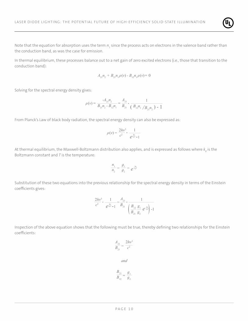
Note that the equation for absorption uses the term n1 since the process acts on electrons in the valence band rather than the conduction band, as was the case for emission.
In thermal equilibrium, these processes balance out to a net gain of zero excited electrons (i.e., those that transition to the conduction band):
A21n2 + B21n1 ρ(v) - B12n1 ρ(v) = 0
Solving for the spectral energy density gives:
ρ(v) = -A21n2
B21n2 - B12n1
= A21
B21
• 1
( B12n1 / B21n2 ) - 1
From Planck’s Law of black body radiation, the spectral energy density can also be expressed as:
ρ(v) = 2hv3
c2•
1
e kBThv -1
At thermal equilibrium, the Maxwell-Boltzmann distribution also applies, and is expressed as follows where kB is the Boltzmann constant and T is the temperature:
n1
n2 =
ɡ1
ɡ2 = e kBT
hv
Substitution of these two equations into the previous relationship for the spectral energy density in terms of the Einstein coefficients gives:
2hv3
c2•
1
e kBThv -1
=A21
B21
• B12
B21
g1
g2( ) -1
1
e kBThv
Inspection of the above equation shows that the following must be true, thereby defining two relationships for the Einstein coefficients:
A21
B21 =
2hv3
c2
and
B21
B12 =
ɡ1
ɡ2
P A G E 1 1
L A S E R D I O D E L I G H T I N G: T H E P OT E N T I A L F UTU R E O F H I G H- E F F I C I E N CY S O L I D-STAT E I L LU M I N AT I O N
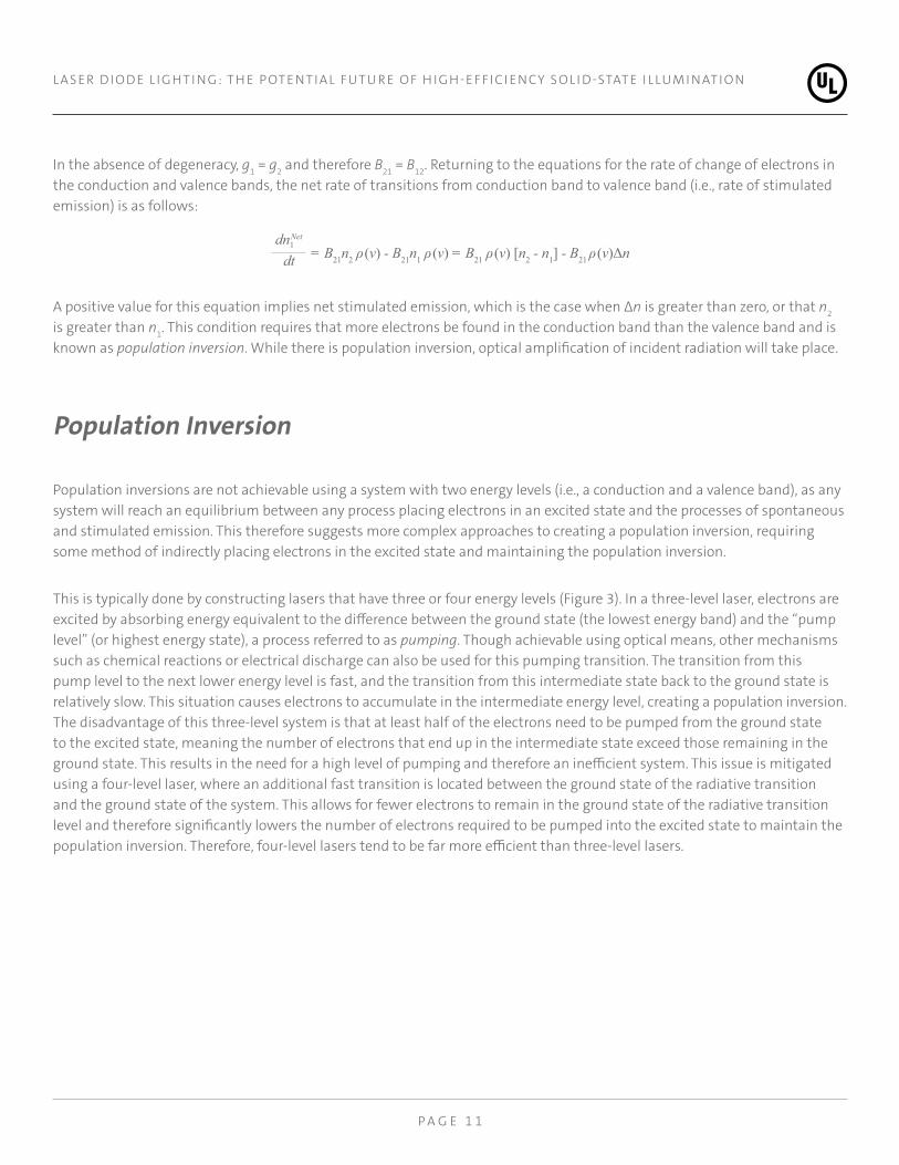
In the absence of degeneracy, g1 = g2 and therefore B21 = B12. Returning to the equations for the rate of change of electrons in the conduction and valence bands, the net rate of transitions from conduction band to valence band (i.e., rate of stimulated emission) is as follows:
dn1 Net
dt = B21n2 ρ(v) - B21n1 ρ(v) = B21 ρ(v) [n2 - n1] - B21 ρ(v)Δn
A positive value for this equation implies net stimulated emission, which is the case when Δn is greater than zero, or that n2 is greater than n1. This condition requires that more electrons be found in the conduction band than the valence band and is known as population inversion. While there is population inversion, optical amplification of incident radiation will take place.
Population Inversion
Population inversions are not achievable using a system with two energy levels (i.e., a conduction and a valence band), as any system will reach an equilibrium between any process placing electrons in an excited state and the processes of spontaneous and stimulated emission. This therefore suggests more complex approaches to creating a population inversion, requiring some method of indirectly placing electrons in the excited state and maintaining the population inversion.
This is typically done by constructing lasers that have three or four energy levels (Figure 3). In a three-level laser, electrons are excited by absorbing energy equivalent to the difference between the ground state (the lowest energy band) and the “pump level” (or highest energy state), a process referred to as pumping. Though achievable using optical means, other mechanisms such as chemical reactions or electrical discharge can also be used for this pumping transition. The transition from this pump level to the next lower energy level is fast, and the transition from this intermediate state back to the ground state is relatively slow. This situation causes electrons to accumulate in the intermediate energy level, creating a population inversion. The disadvantage of this three-level system is that at least half of the electrons need to be pumped from the ground state to the excited state, meaning the number of electrons that end up in the intermediate state exceed those remaining in the ground state. This results in the need for a high level of pumping and therefore an inefficient system. This issue is mitigated using a four-level laser, where an additional fast transition is located between the ground state of the radiative transition and the ground state of the system. This allows for fewer electrons to remain in the ground state of the radiative transition level and therefore significantly lowers the number of electrons required to be pumped into the excited state to maintain the population inversion. Therefore, four-level lasers tend to be far more efficient than three-level lasers.

P A G E 1 2
L A S E R D I O D E L I G H T I N G: T H E P OT E N T I A L F UTU R E O F H I G H- E F F I C I E N CY S O L I D-STAT E I L LU M I N AT I O N
Physical Structure of a Laser Diode
A p-n structure (as shown in Figure 1) is not able to be used to create the needed population inversion, as it would only create a two-level system. Instead, a p-i-n structure is used (where the “i” stands for “intrinsic” layer, or a layer with a much lower dopant concentration than the “p” and “n” layers). A more efficient design is the use of an NpP double heterostructure, where a narrower bandgap semiconductor (for example, GaAs) is sandwiched between two semiconductors of a wider bandgap (such as AlGaAs), as shown in Figure 4. (As shown here, additional layers may be added for enhanced light confinement and other performance improvements.) Under a voltage bias, the electrons are confined into the conduction band by the lower bandgap material, generating the required population inversion.
Figure 5 shows the band diagram for a double heterostructure semiconductor laser, a common manifestation of a four-level laser. In its construction, a lower-doped “p” layer (i.e., a semiconductor with relatively low levels of intentional impurities, or dopants, added to it) of semiconductor is sandwiched between two layers of more highly doped semiconductor with a larger bandgap. The wider bandgap serves as the wider excitation bandgap where pumping occurs (including the “pump layer” and the ground state). The central layer includes the two energy levels that initiate the slow, radiative transition and is the location where the laser light is emitted.
Pump
Fast Transition
Slow, Radiative
Three-Level Laser Four-Level Laser
Exci
tatio
n hv
Pump
Fast Transition
Slow, Radiative
Exci
tatio
n
hv
Fast Transition
Figure 3. Energy diagrams of three- and four-level lasers for sustaining a population inversion.

P A G E 1 3
L A S E R D I O D E L I G H T I N G: T H E P OT E N T I A L F UTU R E O F H I G H- E F F I C I E N CY S O L I D-STAT E I L LU M I N AT I O N
Population inversion alone is not sufficient for laser operation. Light must interact with the electrons in the conduction band to generate the stimulated emission. In lasers, this is done by creating a resonant cavity in which light is reflected back and forth through the laser before being released. Typically, both sides of the cavity have reflecting surfaces, with one of them partially reflecting to allow the laser light to escape (Figure 6). Such a structure is called a Fabry-Pérot resonator. This can be achieved a number of ways, often by cleaving the two ends of the semiconductor crystal to form smooth, parallel edges.
Efc
Ec
Ev
Efv
∆Ec
P-(AIGa)AsN-(GaAI)As P-Ga)As
Figure 4. Representation of the physical construction of a double heterojunction semiconductor laser. Construction starts with the substrate at left, with subsequent layers built up moving towards the right of the diagram.
Figure 5. Energy band diagram for double heterostructure semiconductor laser, shown under voltage bias.
Metal Contact n-type GaAs
substrate
n-type Ga1-xAlxAs
Light guiding and carrier
confinement
~1 μm
n-type Ga1-yAlyAs
Recombination region
~0.3 μm
p-type Ga1-xAlxAs
Light guiding and carrier
confinement
~1 μm
p-type GaAs
Metal contact improvement
layer
~1 μm
Metal Contact

P A G E 1 4
L A S E R D I O D E L I G H T I N G: T H E P OT E N T I A L F UTU R E O F H I G H- E F F I C I E N CY S O L I D-STAT E I L LU M I N AT I O N
Performance Comparisons
Though migration to LEDs for lighting applications has resulted in a significant improvement in efficiency relative to incandescent and fluorescent lighting technologies, further improvements are limited. The current state-of-the-art, phosphor-coated LEDs regularly achieve 140 lm/W for “warm white” LEDs and 160 lm/W for “cool white” lighting, and this technology is expected to be limited to an efficacy of 255 lm/W. Other proposed technologies, including using four separate colored LEDs (red, green, blue, and amber) and “hybrid” technology LEDs, are not likely to exceed efficiencies of 330 lm/W.15 These limitations are attributable to a number of factors, with a comprehensive analysis given elsewhere.9 To increase light output of a given device, the current density is increased, providing more power that is to be converted to light. This increase in power, however, does not result in a linear increase in light output due to nonlinear changes in LED performance. For example, increased power density results in increased junction temperature, which can lead to reduced internal quantum efficiency and increased device electrical resistance. A key factor negatively affecting LED efficiency as current density increases is “current droop.” This phenomenon involves physical mechanisms that are distinctive from thermal effects and may be due to Auger recombination, where electrons and holes recombine (i.e., electrons transition to the valence band) without the release of light.16
Laser medium
Re�ectingSurface
A small amount of light escapes
Partially Re�ecting Surface
Most light
escapes
Coherent laser light
Resonant cavity - tuned to wavelenghtof photons keeps light waves in phase
Figure 6. Example of a resonant cavity for a laser, showing partially reflective surface at one end.
15 J. Kassakian et al., “Assessment of Solid-State Lighting, Phase Two,” The National Academies Press: Washington DC, (2017). (Full text available at: https://www.nap.edu/read/24619/chapter/1).
16 R. Stevenson, “A Definitive Explanation for LED Droop?” IEEE Spectrum, 29 May 2013. (http://spectrum.ieee.org/semiconductors/optoelectronics/a-definitive-explanation-for-led-droop).

P A G E 1 5
L A S E R D I O D E L I G H T I N G: T H E P OT E N T I A L F UTU R E O F H I G H- E F F I C I E N CY S O L I D-STAT E I L LU M I N AT I O N
The overall effect of “current droop” and other thermal effects is to limit efficient LED operation to current densities below roughly 10 A/cm2 (Figure 7). This therefore requires the physical size of an LED to increase or additional LED devices need to be used to attain higher light output. This has an ultimate effect on cost, as well as placing limitations on reducing lighting size for a given light output. As can be seen in Figure 7, power conversion efficiency begins to peak around current densities on the order of 10 kA/cm2, or three orders of magnitude greater than that which is typical for a blue LED. Though efficiencies still tend to be lower than that of state-of-the-art LEDs, work shows promise that higher efficiencies are achievable.18
The significantly higher current densities suggest that light output can be much greater per unit area of the semiconductor device. Notwithstanding other effects, this implies that an equivalent light output can be generated from a 0.1 mm2 die using a blue laser diode as could be generated from a 1 cm2 blue LED device. Even if the laser diode has a significantly higher cost per unit area than that for the LED, the laser diode in principle could result in lower costs since the needed die area is much smaller for a given amount of light output. However, additional factors contribute to size and cost limitations for the laser
Current Density (kA/cm2)
Pow
er C
onve
rsio
n Effi
cien
cy1.0
0.8
0.6
0.4
0.2
0.010-4 10-3 10-2 10-1 100 101 102
SOTA LED Future LED Future LD
SOTA LD
λ ~ 450nm, 80°c
Figure 7. Power conversion efficiency versus current density for LEDs and laser diodes.17
17 J. Wierer and J. Tsao, “Advantages of III-nitride laser diodes in solid-state lighting,” Physica Status Solidi A, vol. 212, no. 5, pp. 980-985, (2015).
18 C. Vierheilig, et al., “Beyond blue pico laser: Development of high power blue and low power direct green,” Proceedings of SPIE, 8277, (2012).

P A G E 1 6
L A S E R D I O D E L I G H T I N G: T H E P OT E N T I A L F UTU R E O F H I G H- E F F I C I E N CY S O L I D-STAT E I L LU M I N AT I O N
diode, most notably the limited die to heat sink area.9 Limitations on heat sink area for practical devices restrict the ability to control temperature rise at the diode junction and therefore set an upper threshold for achievable current density, with research into more exotic heat sinking technologies such as chemical vapor-deposited (CVD) diamond microchannels used for improving thermal conductivity to the heat sink.19
Applications
Despite the promise of laser lighting giving significant advantages in efficiency and potentially serving as a catalyst for new lighting concepts, current commercial applications that use laser lighting are limited. One of the more well-known applications of laser lighting has been in automotive headlights. In the 2014 model year, BMW included headlamps driven by laser diodes for their i8 “hybrid supercar.”20 The laser light sources were provided by Osram.21 These headlamps have an advantage of emitting high-intensity light at a color temperature of 5500-6000K, the highest temperature international regulations currently allow, which should reduce driver eye fatigue. This is in comparison to xenon high-intensity discharge (HID) headlamps which have a color temperature around 4000K and therefore will appear yellower than the laser lighting. Another advantage of the laser headlamp is an improved ability to focus the light into the desired direction due to the nature of laser’s coherent light output and small light emitting area (reportedly 10 μm2, compared with typical LED areas of 1 mm2).20 Efficiency is also higher, with the laser headlamps using less than 30W, compared to 40W for LED headlamps and 120W for incandescent and xenon headlamps. Illumination distance is also reportedly doubled, from 300 m to 600 m when compared to an LED highbeam (Figure 8).
Audi also introduced laser headlamps, first in low volume (99 units) in the 2015 R8 LMX supercar, which operate only above 37 mph and emit light at 5500K at three times the legally allowed 150 kcd in the United States, and at twice the distance attainable by the LED headlamps in the Audi R8 model.22 A more recent development is the Matrix Laser headlamp, which
19 K. Goodson et al., “Improved Heat Sinking for Laser-Diode Arrays Using Microchannels in CVD Diamond,” IEEE Transactions on Components, Packaging, and Manufacturing Technology – Part B, vol. 20, no. 1, pp. 104-109, (1997).
20 L. Ulrich,”BMW Laser Headlights Slice Through the Dark,” IEEE Spectrum, October 2013. (http://spectrum.ieee.org/transportation/advanced-cars/bmw-laser-headlights-slice-through-the-dark)
21 “Osram is the System Partner for Laser Light in the BMW i8,” Osram Press Release, 21 February 2014, (https://www.osram.com/osram_com/press/press-releases/_trade_press/2014/osram-is-the-system-partner-for-laser-light-in-the-bmw-i8/index.jsp)
22 J. Meiners, “2015 Audi R8 LMX V-10,” Car and Driver, July 2014. (http://www.caranddriver.com/reviews/2015-audi-r8-lmx-first-drive-review)

P A G E 1 7
L A S E R D I O D E L I G H T I N G: T H E P OT E N T I A L F UTU R E O F H I G H- E F F I C I E N CY S O L I D-STAT E I L LU M I N AT I O N
includes an array of hundreds of thousands of micromirrors that allows the beam to be redirected up to 5,000 times a second. This technology allows light to be redirected onto oncoming objects, enabling the ability to project signs and other information onto the ground and surrounding environment. The technology allows operation in a permanent “high beam” setting, with the beam being redirected when oncoming traffic is detected. This latter feature violates a 1968 American law that requires a manual ability to switch between high and low beams, and that separate light sources are required.24 The Matrix Laser technology was a collaborative effort with Audi, Bosch, Osram Licht AG, and the Karlsruhe Institute of Technology, sponsored by the German federal education and research ministry.23
Additional lighting applications have been proposed, but do not appear to be widely commercialized. Use of laser lighting has been proposed for general illumination, citing enhanced efficiency and narrower beams for spotlighting and accent lighting
23 L. Ulrich, “Audi Pixelated Laser Headlights Light the Road and Paint It Too,” IEEE Spectrum, 6 May 2015, (http://spectrum.ieee.org/cars-that-think/transportation/advanced-cars/audi-lights-the-road-with-pixelated-laser-headlights-)
24 E. Adams, “Too Bad Audi’s Swanky New Headlights Aren’t Allowed in the US,” Wired, 12 January 2017, (https://www.wired.com/2017/01/bad-audis-swanky-new-headlights-arent-allowed-us/)
100 METRES
300 METRES
600 METRES
LED LOW BEAM LED HIGHBEAM LED HIGHBEAM WITHLASER LIGHT
Figure 8. Comparison of LED and laser headlamps for the BMW i8. (Source: http://blog.lightopiaonline.com/lighting-articles/bmw-introduces-laser-headlights/.)

P A G E 1 8
L A S E R D I O D E L I G H T I N G: T H E P OT E N T I A L F UTU R E O F H I G H- E F F I C I E N CY S O L I D-STAT E I L LU M I N AT I O N
applications.25 Another concept suggests using optical waveguides or fiber optic cables to illuminate buildings using several small yet powerful laser light sources.26 In this scenario, high-intensity light would be generated at only a few points in the building, with light directed throughout the building using fiber optic cabling or some other type of waveguide. This would allow for additional light to be added without altering the electrical system.
Conclusions
Laser diodes are not a new technology but are relatively new as applied to solid state lighting applications. Their ability to achieve high output efficiencies at very high power densities (100 to 1000 times that of blue LEDs) enables high light output with much smaller die size. These high densities are of particular interest in automotive applications, such as high-intensity headlamps, and may lead to new means of delivering lighting to buildings using novel approaches such as fiber optic cabling and other waveguides.
White laser lighting follows a similar concept to white LED lighting, where blue light is generated by a solid-state diode source and then downconverted through the use of a yellow-emitting phosphor. The key difference between a laser diode and an LED is that laser diodes primarily emit by means of stimulated emission and an LED emits by spontaneous emission. Stimulated emission results in optical amplification with highly coherent and directional light.
Commercial applications are limited by overall cost considerations and regulatory issues. Cost of laser lighting continues to be significantly higher than that for blue LEDs, though the higher power densities may allow for reduced cost of blue laser lighting as less die area is required for a given amount of light output. However, it is unclear whether such an advantage can overcome the large established manufacturing infrastructure of conventional white LED technologies. It is expected that costs will continue to drop as the technology matures and more widespread adoption of laser lighting technology will likely occur when its advantages outweigh the increased cost. For example, the use of laser lighting in automotive headlamps is of particular interest as the technology brings several advantages in beam distance and efficiency that are not achievable with other technologies. However, regulatory issues prevent many of these advantages from being included in production vehicles, especially within the United States. This application therefore requires regulatory changes before laser lighting can be introduced into the American automotive market. Considering this obstacle and the fact that most automotive laser lighting work is being conducted with European manufacturers, it is likely that laser lighting will first enter the European market, with changes in American regulations to follow should the technology prove popular in Europe.
25 SoraaLaser website, citing different applications of technology, (http://soraalaser.com/illumination/). According to their website, SoraaLaser is currently shipping pre-production samples, and as of mid-2017 the site continues to state that commercial release is planned for 2016.
26 C. Mims, “Forget LED bulbs—the future of interior lighting is lasers,” Quartz, 13 November 2013, (https://qz.com/146761/forget-led-bulbs-the-future-of-interior-lighting-is-lasers/)