
PATTERNS IN NETWORK ARCHITECTURE: A CLOUD COMPUTING · A A A A A A CLOUD COMPUTING OUTLINE...
25
PATTERNS IN NETWORK ARCHITECTURE: CLOUD COMPUTING
Transcript of PATTERNS IN NETWORK ARCHITECTURE: A CLOUD COMPUTING · A A A A A A CLOUD COMPUTING OUTLINE...

AAA
A
A
A
PATTERNS IN NETWORK ARCHITECTURE:
CLOUD COMPUTING

AAA
A
A
A
CLOUD COMPUTING
OUTLINE
Discussion of Alloy homework (net4.als)
Discussion of “VL2: A scalable and flexible data center network”
Discussion of “Stratos: A network-aware orchestration layer for virtual middleboxes in clouds”
The Nicira paper
Models of VL2 and SEATTLE
Model of a cloud design and comparisons to literature
123
4
5
6

AAA
A
A
A
IP SUBNETWORK FOR VLAN, ...1/24 IP SUBNETWORK FOR VLAN ...2/24 members of each subnet are directly connected by virtual links
IP
links of a VLAN mustform a self-contained spanning tree
VLAN X VLAN Y
LAN A LAN B
all members of VLAN X must beconnected to this LAN
all members of VLAN Y must beconnected to this LAN
although each LAN has2 access routers, inter-LANbandwidth is severely limited
VLAN TECHNOLOGY (ACCORDING TO VL2 PAPER)
1.11.2
M2M1
M3 M0 M5
M6
1.0 2.52.6
2.7
M7M8

AAA
A
A
A
VL2 ARCHITECTURE
A4
A9
A2
A7
connections to the publicInternet are not shown
VL2:names are a random subset of the AA space
members are fully connectedby dynamic links
a member is a virtual machine,meaning the data andprocessing state—whatmight be called the VM “image”
a VM can migrate from onelocation to another, without changing anythingin the VL2

AAA
A
A
A
session with src = 2.55, dest = 2.56
TOR has a hardware/software link to eachof its VMs, and arouting table of itsAAs
session with identifier H(t), dest 1.6
this member is a mysterious,undefined “server”—it isactually a VM share on a virtualized host, which gets itsname dynamically by VM mobility
VL2 ARCHITECTURE
directorylookup
intermediateswitch aggregation switches are
in here; presumablyrouting is deterministicand not interesting
2.562.55
2.55 1.6
TOR2.56
VL2

AAA
A
A
A
session with src = 2.55, dest = 2.56
session with identifier H(t), dest 1.6
1
2
3
4
5
links and sessions 1, 2, 3, 4, 5 are inone-to-one correspondence, so everyuser session gets a different randompath to intermediate switches
the underlay network usesitself, but there are no cyclesin link usage
VL2 ARCHITECTURE
1.1
1.1
1.1
1.1TOR and
aggregationswitches
session with identifierH(t), dest 1.1
2.562.55
2.55
2.55
1.6
TOR2.56
VL2

AAA
A
A
A
Ethernethosts areconnected to switches there is an
overlay in whichall switch pairs areconnected by direct,persistent links
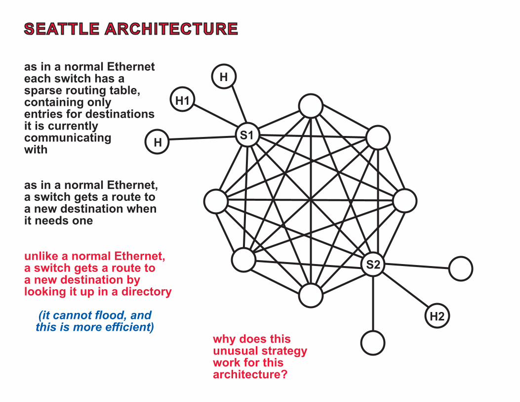
SEATTLE ARCHITECTURE
in an underlay, all these linksare implemented by anetwork with normal routing;it is better than a LAN becauselinks need not be confined toa spanning tree a
AAA
A
A
A
SEATTLE ARCHITECTURE
H
H
H1
H2
S1
S2
as in a normal Etherneteach switch has asparse routing table,containing onlyentries for destinationsit is currentlycommunicatingwith
as in a normal Ethernet,a switch gets a route toa new destination whenit needs one
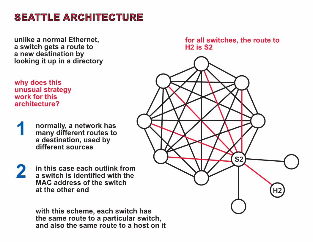
unlike a normal Ethernet,a switch gets a route toa new destination bylooking it up in a directory
(it cannot flood, andthis is more efficient)
why does thisunusual strategywork for thisarchitecture?
AAA
A
A
A
for all switches, the route toH2 is S2
SEATTLE ARCHITECTURE
H2
S2
unlike a normal Ethernet,a switch gets a route toa new destination bylooking it up in a directory
why does thisunusual strategywork for thisarchitecture?
1
2
normally, a network hasmany different routes toa destination, used bydifferent sources
in this case each outlink froma switch is identified with theMAC address of the switch at the other end
with this scheme, each switch hasthe same route to a particular switch,and also the same route to a host on it

AAA
A
A
A
MIDDLEBOXES IN CLOUD COMPUTING
LOGICAL PROBLEMS OF SERVICE CHAINING
routing loops
large number of switch-level forwarding rules
session affinity
middleboxes that modify the 5-tuple used toidentify packets
middleboxes that classify packets
PROBLEMS OF DEPLOYMENT AND DYNAMICRESOURCE ALLOCATION
how is service chaining deployed in a clouddata center?
what happens when load must beredistributed?
what happens when a virtual machinemigrates?

A CLOUD DESIGN
SOME SOURCES
CloudNaaS [Benson, Akella, Shaikh 11]
VL2 [Greenberg et al. 09]
WL2 [Chen, Liu, Liu, Loo, Ding 14]
OpenStack
DESIGN GOALS
accommodate clouds of the largestsize
10 data centers100 K hosts per data center,
100 M virtual machines
put in all the capabilities desirablein large-scale, multi-tenant clouds
multiple data centers,VM migration
tenant-specific links
tenant-specific address spaces,policy links
identifier/locator split,IP routing in cloud layer
NEW SOURCES AND COMPARISONS
SIMPLE
Stratos
Tenant Service Networks
Cloud Network
Ethernet LANs
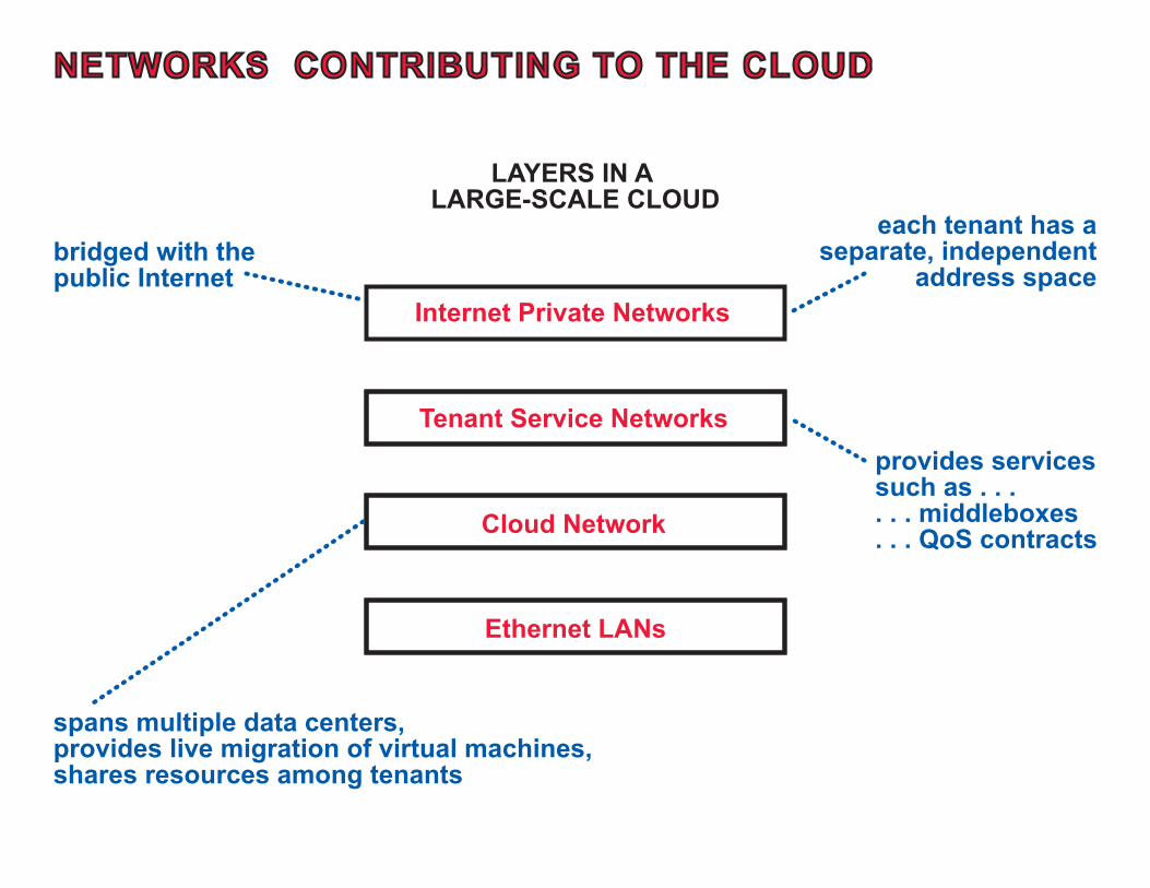
NETWORKS CONTRIBUTING TO THE CLOUD
Internet Private Networks
LAYERS IN A LARGE-SCALE CLOUD
bridged with thepublic Internet
provides servicessuch as . . . . . . middleboxes. . . QoS contracts
each tenant has aseparate, independent
address space
spans multiple data centers,provides live migration of virtual machines, shares resources among tenants

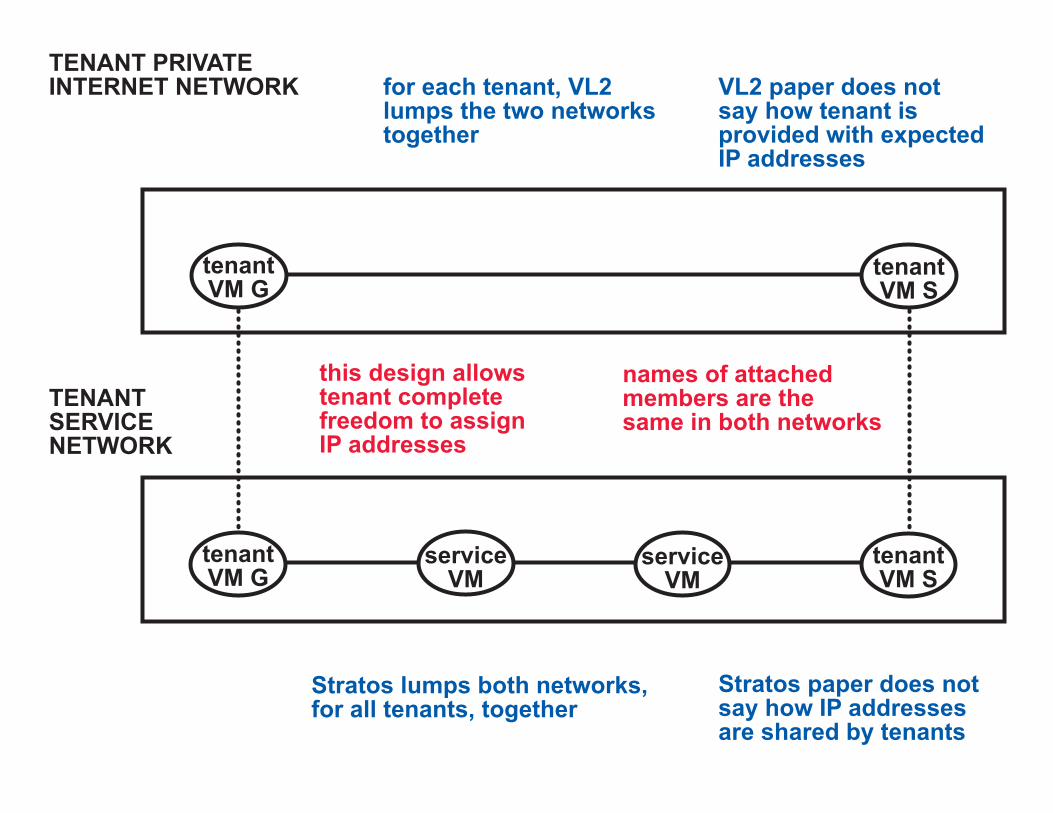
TENANT PRIVATEINTERNET NETWORK
tenantVM G
tenantVM S
serviceVM
serviceVM
tenantVM G
tenantVM S
TENANTSERVICENETWORK
gatewaytenantserver
cloud-suppliedservice functions
(middleboxes)
TENANT PRIVATEINTERNET NETWORK
tenantVM G
tenantVM S
serviceVM
serviceVM
tenantVM G
tenantVM S
TENANTSERVICENETWORK
for each tenant, VL2lumps the two networkstogether
VL2 paper does notsay how tenant isprovided with expectedIP addresses
this design allowstenant completefreedom to assignIP addresses
names of attachedmembers are thesame in both networks
Stratos lumps both networks,for all tenants, together
Stratos paper does notsay how IP addressesare shared by tenants

TENANT PRIVATEINTERNET NETWORK
each link is associatedwith a service chain(sequence of middleboxtypes) and a load ofsessions
each new session is assigned to a link accordingto policy and load
forwarding hereimplements the assignment
virtuallink
at each member, there isa forwarding entry forevery session going through it
k
k’
s
s to k’
tenantVM G
tenantVM S
serviceVM
serviceVM
tenantVM G
tenantVM S
TENANTSERVICENETWORK
user sessions
each link above implemented by a session (header = ident)

TENANT PRIVATEINTERNET NETWORK
k
k’
s
s to k’with care, the sessionidentifier passes throughmiddleboxes that change headers
tenantVM G
tenantVM S
serviceVM
serviceVM
tenantVM G
tenantVM S
TENANTSERVICENETWORK
user sessions
assignment of individualuser sessions to the“flow” that is session sprovides redistributionof load with sessionaffinity
the tag in Stratos is this session identifier
VL2 paper does not haveservice chaining
middleboxes cannotdo packet classification
only Dysco allows this
k’
s
s to k’
k’
s
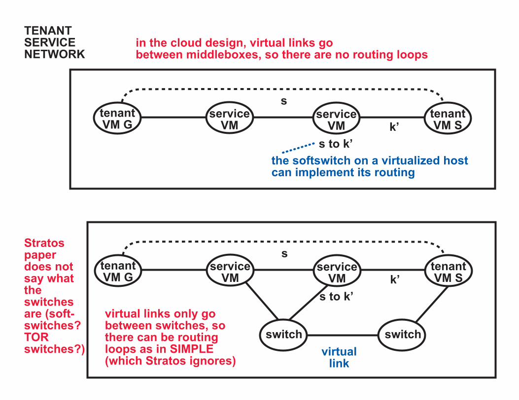
s to k’virtual links only go between switches, sothere can be routingloops as in SIMPLE (which Stratos ignores)
virtuallink
switchswitch
tenantVM G
tenantVM S
serviceVM
serviceVM
TENANTSERVICENETWORK
tenantVM G
tenantVM S
serviceVM
serviceVM
in the cloud design, virtual links gobetween middleboxes, so there are no routing loops
the softswitch on a virtualized hostcan implement its routing
Stratospaperdoes notsay whattheswitchesare (soft-switches?TORswitches?)

TENANTSERVICENETWORK
implementation location
shareshare share share
soft-switch
soft-switch
gate-way
gate-way
SHAREDCLOUDNETWORK
tenantVM
tenantVM
serviceVM
serviceVM
trunk betweendata centers
implemented byhypervisor ofshared machine
link inside a data center(TORs and other switches
can be here, too)
this is like VL2, except . . .
. . . location lookup isby (tenant, name)
. . . VL2 has much moredetail about efficientcommunication withina data center
Stratos has an underlay implementing virtual linksbetween switches but it does not extend to middleboxesand does not provide for migration of VMs

DISTINCTINTERNET LAYERS
DISTINCT SERVICE LAYERS
VM MIGRATION: CLOUD LAYER HIERARCHY
sliceslice slice
slicesoft-switch
soft-switch
gate-way
gate-way
host hostswitch switch
VM VMVM
DISTINCTETHERNET LAYERS divided by geography
onedatacenter
anotherdata
center
divided by ownership
SHARED CLOUDLAYER
one tenant another tenant
Tenant U
1.5.8.77
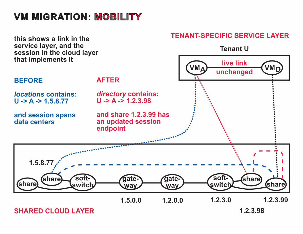
this shows a link in theservice layer, and the session in the cloud layerthat implements it
TENANT-SPECIFIC SERVICE LAYER
live linkunchanged
BEFORE
locations contains:U -> A -> 1.5.8.77
and session spansdata centers
AFTER
directory contains:U -> A -> 1.2.3.98
and share 1.2.3.99 hasan updated sessionendpoint
VM MIGRATION: MOBILITY
shareshare share
sharesoft-switch
soft-switch
gate-way
gate-way
VM VM
SHARED CLOUD LAYER1.2.3.99
1.2.3.981.2.3.01.2.0.01.5.0.0
A D

Tenant U
live linkunchanged
we want to verify that a tenant’s VMcan never receive messages fromanother tenant’s VM
enforcement is by means of tenant-specific links in the cloud layer (implemented on shared links inthe Ethernet layers)
U
U
U
T
VM MIGRATION: A THREAT TO TENANT ISOLATION
share
share
soft-switch
gate-way
VM VM
1.2.3.991.2.3.98
A D
before share 1.2.3.98 was allocatedto Tenant U, it belonged toTenant T, which is stillsending messages to it
when the share changes tenants,its link must also changeownership, atomically
if it is proved that forwarding is limitedto chains of links of the same tenant,tenant isolation should be guaranteedby this layer

MIDDLEBOX POLICIES: UPDATES ARE CONSISTENT BY CONSTRUCTION
VM
IP IPA
A D
D
B C VM
INTERNET LAYER
SERVICE LAYER
detect need formore capacity
create newpolicy link
create newservice session
allocate middleboxes,create links and forwarding
for session application sessions are not allocatedto new policy link until this call returns
LAYEREDCONTROL PROGRAMS
VM
VIP VIPA
A D
D
B C VM
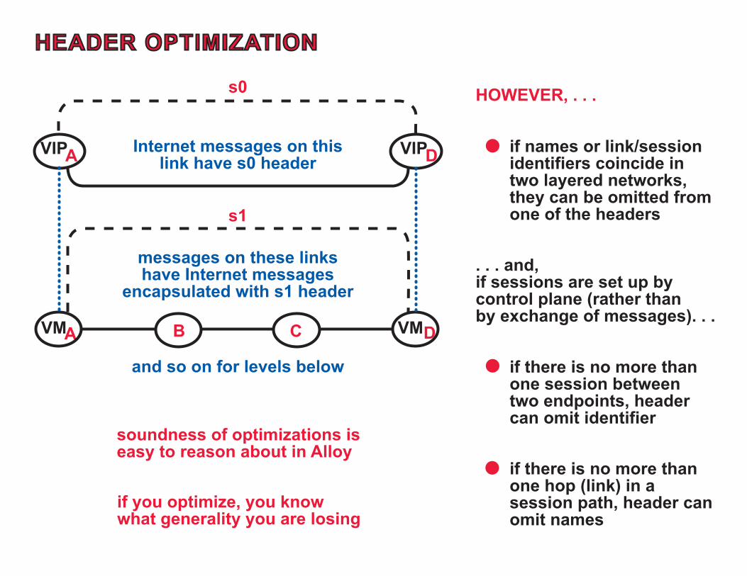
HEADER OPTIMIZATION
s0
s1
Internet messages on thislink have s0 header
messages on these linkshave Internet messages
encapsulated with s1 header
and so on for levels below
HOWEVER, . . .
. . . and,if sessions are set up bycontrol plane (rather thanby exchange of messages). . .
if there is no more thanone session betweentwo endpoints, headercan omit identifier
if there is no more thanone hop (link) in asession path, header canomit names
if you optimize, you knowwhat generality you are losing
if names or link/sessionidentifiers coincide intwo layered networks,they can be omitted fromone of the headers
soundness of optimizations iseasy to reason about in Alloy

SUMMARY: REASONING WITH THE FORMAL MODEL
LOGICAL EFFECTIVENESS ORREACHABILITY
for propagation of top-downchanges due to tenantconfiguration, policies, or load
for propagation of bottom-upchanges due to mobility, resourcefailure, or resource reconfiguration
verified separately for each layer
verified separately for each layer verified separately for each layer
SECURITY
only allowed and authenticatedmessages are delivered
middlebox policies are enforced bythe service layer
one tenant’s VM cannot receivemessages from another tenant’sVM in the cloud layer
BANDWIDTH TRACEABILITY(SUPPORT FOR QoS CONTRACTS)
load from each tenant is formallydefined and traceable
HEADER OPTIMIZATION (WHENPOSSIBLE TO OMIT FIELDS)
UPDATE CONSISTENCY
consistency by construction,using informal hierarchical reasoning
verification and informalreasoning, both hierarchical
legitimate destinations arereachable from legitimate sources
the mobility mechanism alwayssucceeds in the cloud layer
even without central control, bothendpoints moving simultaneously

AAA
A
A
A
NETWORK VIRTUALIZATION IN
MULTI-TENANT DATACENTERS
by Teemu Koponen and 24 others, mostly from VMware
NSDI `14
This is believed to be the ultimatecloud design, but no one understandsthe paper. Good time to try again.


