PATRIOT SERIES LECTERNS
8
PATRIOT SERIES LECTERNS SN3040 / SS3040 / SW3040 / SN3045 / SS3045 / SW3045 SN3040A / SN3045A / SS3045A / SW3045A Thank you for choosing the Patriot, Patriot Plus and Patriot Power Lift Lecterns from AmpliVox Portable Sound Systems. We are excited in introducing this truly unique lectern. Our lectern combines flexibility with functionali- ty. Please refer to this user guide as you enjoy the unique capabilities of another quality product from AmpliVox Portable Sound Systems. We encourage you to visit our website www.ampli.com to register your product for its warranty cover- age, sign up to receive our newsletter, download our catalog, and learn more about the complete line of AmpliVox audio visual products, including portable PA systems, and lecterns. AmpliVox ● 650 Anthony Trail, Suite D, Northbrook, IL 60062 ● Phone: (800)267-5486 ● Fax: (800)267-5489 www.ampli.com FIXED HEIGHT ADJUSTABLE HEIGHT
Transcript of PATRIOT SERIES LECTERNS

PATRIOT SERIES LECTERNS
SN3040 / SS3040 / SW3040 / SN3045 / SS3045 / SW3045
SN3040A / SN3045A / SS3045A / SW3045A
Thank you for choosing the Patriot, Patriot Plus and Patriot Power Lift Lecterns from AmpliVox Portable Sound Systems. We are excited in introducing this truly unique lectern. Our lectern combines flexibility with functionali-ty. Please refer to this user guide as you enjoy the unique capabilities of another quality product from AmpliVox Portable Sound Systems. We encourage you to visit our website www.ampli.com to register your product for its warranty cover-age, sign up to receive our newsletter, download our catalog, and learn more about the complete line of AmpliVox audio visual products, including portable PA systems, and lecterns.
AmpliVox ● 650 Anthony Trail, Suite D, Northbrook, IL 60062 ● Phone: (800)267-5486 ● Fax: (800)267-5489 www.ampli.com
FIXED HEIGHT ADJUSTABLE HEIGHT

2
2
1
IMPORTANT SAFETY INSTRUCTIONS
Before using this product, read the instruction manual for important safety information. Please retain this manual for
future reference and warranty information.
Troubleshooting & Servicing
Do not attempt to service or repair the device yourself. Refer all servicing to qualified service personnel. Do not at-
tempt to modify the device in anyway. Doing so could invalidate your warranty.
Cleaning
When cleaning the device, please use a soft, dry cloth. Never use benzene, paint-thinner, or other chemicals on the
device.
Location Place the device in stable location, so it will not fall causing damage to the device or bodily harm.
Intended use
The product may only be used with the original parts intended for it. The intended use includes adherence to the speci-
fied installation instructions. The manufacturer accepts no liability for damage arising due to improper use.
WARNING: Changes or modifications to this unit not expressly approved by the party responsible for compliance
could void the user’s authority to operate the equipment.
The exclamation point within an equilateral triangle is intended to alert the user to the presence of important operating and maintenance instructions in this owner’s guide.
IMPORTANT
This device complies with Part 15 of the FCC Rules. Operation is subject to the following two conditions:
(1) This device may not cause harmful interference, and (2) this device must accept any interference received, includ-
ing interference that may cause undesired operation.
The unit’s circuitry may cause interference to nearby radios. To prevent interference, either switch the unit off or move
away from the affected radio.
NOTE: This equipment complies within the limits for a class B digital device, pursuant to Part 15 of the FCC Rules.
These limits are designed to provide reasonable protection against harmful interference in a residential installation.
This equipment generates, uses and can radiate radio frequency energy and, if not installed and used in accordance
with the instructions, may cause harmful interference to radio communications. However, there is no guarantee that
interference will not occur in a particular installation. If this equipment does cause harmful interference to radio or tele-
vision reception, which can be determined by turning the equipment off and on, the user is encouraged to try to correct
the interference by one or more of the following measures:
• Increase the separation between the equipment and receiver.
• Connect the equipment into an outlet on a circuit different from that to which the receiver is connected. • Consult the dealer or an experienced radio / TV technician for help.
NOTE: Shielded cables may be required to be used with this unit to ensure compliance with the Class B FCC limits.

3
Model SN3040
• No additional accessories
Model SS3040
• S805A 50 Watt Stereo Amplifier • Gooseneck Microphone
Model SW3040
• SW805A 50 Watt Stereo Amplifier with built-in 16 Channel UHF Wireless Microphone Receiver
• Gooseneck Microphone • Wireless Microphone
Model SN3045
• No additional accessories
Model SS3045
• S805A 50 Watt Stereo Amplifier • Gooseneck Microphone, Reading Light, Clock
Model SW3045
• SW805A 50 Watt Stereo Amplifier with built-in 16 Channel UHF Wireless Microphone Receiver
• Gooseneck Microphone, Reading Light, Clock • Wireless Microphone
Model SN3040A
• No additional accessories
Model SN3045A
• No additional accessories
Model SS3045A
• S805A 50 Watt Stereo Amplifier • Gooseneck Microphone, Reading Light, Clock
Model SW3045A
• SW805A 50 Watt Stereo Amplifier with built-in 16 Channel UHF Wireless Microphone Receiver
• Gooseneck Microphone, Reading Light, Clock • Wireless Microphone
PACKAGE CONTENTS
SPECIFICATIONS
Model S805A Amplifier System
• Power Output - 50 Watt RMS into 4 ohms
• AC/DC Operation
• Stereo Speaker Output
• 3.5mm Line Output
• 3.5mm Line Input
• Separate Volume and Tone Control for Line Input
• Master Volume Control
Wireless System Model SW805A
• Built-in UHF Selectable 16 Channel Receiver with RF Signal LED
• Wireless Range: 300 feet
PATRIOT
PATRIOT PLUS
PATRIOT POWER LIFT
PATRIOT POWER LIFT PLUS

4
SET-UP
The lectern is shipped at its lowest height. To raise lectern you must plug power supply into wall outlet. Power cords are bundled for shipment and are taped to the inside of the top cabinet door (A). Open door and locate power cord for AC power supply. Temporarily pull cord through this open door and plug into AC outlet. Locate power lift switch on right backside face of lectern (B). Switch toggles between up and down. Press top of switch to raise lectern. Press bottom of switch to lower lectern. Raise lectern to its highest point. Locate the two cable outlets. One on each side of the lift tower near the front of the lectern (C). Use these openings to run cables through. When running cables through the cable openings remember to leave enough cable slack to allow for the raising /lowering of the lectern. Lower lectern down when complete with any wiring.
MICROPHONE AND LIGHT
To access the microphone and light compartment, push down on door at the front of lectern work area. Door will pop up. Lift to open.
Looking down inside you will see two brass knobs on wood dowel rods. Pull these two knobs up. This will raise the shelf. Pull up until shelf locks into place. Lower both knobs slowly back down.
With shelf now locked into place you can mount the gooseneck microphone. Pull out the XLR plug from the microphone holder located on the left side. Align pins from the gooseneck microphone with the 3 holes in plug. Insert microphone into plug until it locks into place. Push microphone back into holder until it is firmly held by rubber boot.
CAUTION: If microphone plug ever falls into microphone holder you will need to remove the panel that has two brass screws hold-ing it in place. To access panel, lower work surface into the flat position. You will see the two brass screws, one on each side of the panel. Remove screws and pull panel toward you.
A
B
C
UP
DOWN
Many of the Patriot Lecterns have the same features. Not all features shown will be on your lectern. Please review them all and if you have any questions please give us a call.
1-800-267-5486, 8am-6pm M-F CST
If using S805A or SW805A amplifier. Place on shelf after making connections.
5
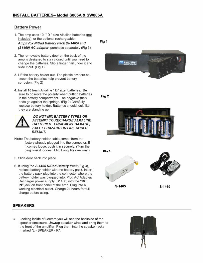
• Looking inside of Lectern you will see the backside of the speaker enclosure. Unwrap speaker wires and bring them to the front of the amplifier. Plug them into the speaker jacks marked "L - SPEAKER - R".
SPEAKERS
Battery Power
1. The amp uses 10 " D " size Alkaline batteries (not included); or the optional rechargeable
AmpliVox NiCad Battery Pack (S-1465) and
(S1460) AC adapter, purchase separately (Fig 3).
2. The removable battery door on the back of the
amp is designed to stay closed until you need to change the batteries. Slip a finger nail under it and slide it out. (Fig 1)
3. Lift the battery holder out. The plastic dividers be-
tween the batteries help prevent battery corrosion. (Fig 2)
4. Install 10 fresh Alkaline " D" size batteries. Be
sure to observe the polarity when putting batteries in the battery compartment. The negative (flat) ends go against the springs. (Fig 2) Carefully
replace battery holder. Batteries should look like they are standing up.
DO NOT MIX BATTERY TYPES OR ATTEMPT TO RECHARGE ALKALINE BATTERIES. EQUIPMENT DAMAGE, SAFETY HAZARD OR FIRE COULD
RESULT.
Note: The battery holder cable comes from the factory already plugged into the connector. If
it comes loose, push it in securely. (Turn the plug over if it doesn’t fit; it only fits one way.)
5. Slide door back into place.
6. If using the S-1465 NiCad Battery Pack (Fig 3),
replace battery holder with the battery pack. Insert the battery pack plug into the connector where the battery holder was plugged into. Plug AC Adapter/ Recharger power supply (S1460) into the “DC IN” jack on front panel of the amp. Plug into a working electrical outlet. Charge 24 hours for full charge before using.
Fig 3
Fig 2
Fig 1
S-1465 S-1460
INSTALL BATTERIES– Model S805A & SW805A

6
1. Power Switch.
2. Power Indicator Light. Turns red when power is turned on.
3. Mic Volume Control. This knob con-trols output loudness to all 3 microphone inputs and Siren.
4. Dynamic Mic Jack. Dynamic is one kind of microphone. AmpliVox’s wired, hand-held microphone is this type.
5. Auxiliary Volume Control. This vol-ume knob controls the auxiliary volume separately from the microphone volume.
6. Tone Control. This knob controls the tone of the auxiliary input. Turn counter-clockwise for more bass or clockwise for more treble. (The mic jacks don’t need a tone control because they have been pre-optimized for the human voice.
7. Left & Right Speaker Jacks. Two sepa-rately amplified speaker jacks allow you to use one or two speakers for additional sound power or true stereo output.
8. Line Out Jack. Can be used with a tape recorder The Line Out Jack outputs all the sound from the 3 microphone inputs and the auxiliary input.
9. Auxiliary Line In Jack. To play music, just plug in your CD player, MP3 player or Amplivox’s Bluetooth Receiver.
10. Wireless Mic Jack. Optional second wireless receiver (S1690R) plugs in here. Then plug AmpliVox’s lapel or headset mi-crophone into the transmitter. Now you are hands-free anywhere within a 300- foot radi-us of the receiver.
11. Condenser Mic Jack—with phantom power. If you don’t know what phantom power is, then you don’t need to know, but a condenser microphone won’t work without it. If you have a AmpliVox lapel or headset micro-phone, and not using the wireless transmitter, plug them in here.
12. Aux Out. For optional 12-15 volt accessory.
13. DC In Jack. Used for the 12V Battery Cable, 12V Power Plug or the optional International AC Adapter/Recharger, plug it in here. Plug the other end into a wall / floor outlet.
14. Wireless ON/OFF Switch Switches power on to the built-in 16 channel wireless receiver.
15. Wireless 16 Channel Selector Channel that you select here must match with the channel that is selected on the bodypack / handheld microphone transmitter.
16. OPTIONAL—Wireless 16 Chan-nel UHF Bodypack Microphone Transmitter (S1690T) or Wireless Handheld Transmitter (S1695).
15. Wireless 16 Channel Selector (left side of case)—rotate knob to select wire-
less channel on the built-in receiver. RF LED will light up when receiving signal from transmitter.
16. Optional—Wireless 16 Channel UHF Bodypack and Handheld Micro-phone Transmitter (S1690T & S1695)
Model SW805A Wireless Features
MODEL S805A & SW805A AMPLIFIER FEATURES
1. Power Switch
2. Power Indicator Light
3. Mic Volume-controls all 3 mic inputs
4. Dynamic Mic Jack— 1/4 ″ for wired, hand-held mic.
5. Auxiliary Volume— controls the auxiliary input separately from the mic volume
6. Tone Control— for auxiliary input; counter-clockwise for more bass; clock-wise for more treble
7. Left & Right Speaker Jacks— 1/4 ″
8. Line Out—3.5mm record your presentation with a tape recorder or a computer sound card
9. Auxiliary Line In— 3.5mm add music with a tape player, CD or MP3 player
10. Wireless Mic Jack -3.5mm for optional wireless receiver
11. Condenser Mic Jack - 3.5mm for lapel or headset mic
12. Aux Out - for optional 12-15 volt accessory.
13. DC In Jack — plug in optional Universal AC Adapter/ Recharger for power.
14. Wireless ON/OFF Switch Model SW805A
Channel selected must match
Plug handheld microphone into the “DYNAMIC” jack. Check to see that you have plugged in your speakers. Turn amplifier on. Turn microphone on and talk into microphone. Rotate “VOLUME” control knob to obtain desired loudness level. For wireless microphone use slide the “ON-OFF” switch to “ON”. Switch is located just below main power switch of amplifier. Make sure both transmitter and receiver are on same frequency channel. Turn “ON” wireless transmitter (S1690T or S1695). RF LED on side of amplifier will light, meaning that it is receiving signal. If RF LED does not light, check channel numbers.
To Operate:
15. Wireless Channel Selector Model SW805A

7
WIRELESS BODYPACK TRANSMITTER—OPTIONAL— MODEL S1690T
BATTERIES
1. Hold the body of microphone in hand and twist off bottom section of microphone.
2. Insert two “AA” batteries.
3. Twist bottom section back on to microphone.
BATTERY STATUS
The life expectancy of the two batteries is about 10 hours. When the “BATTERY” symbol on the display screen keeps flashing the batteries should be replaced immediately.
Functions 1) Interchangeable Microphone Head
2) LCD Screen
3) Power / Mute Control Switch
4) Select Button
5) Microphone Input Sensitivity Adjustment—is used to set the gain of microphone. If you are a soft talking speaker you will need to turn the control counter clockwise. Turn clock-wise if you are a loud talker. Use plastic screwdriver that is supplied.
• TURN ON MICROPHONE: Press and hold the “POWER/MUTE” (3) button until LCD screen lights up.
• TO MUTE: Press “POWER/MUTE” button twice to MUTE. Channel number will flash when mut-ed. Press button again twice to
remove “MUTE”.
• TURN OFF MICROPHONE: Press and hold the “POWER/MUTE” (3) button for 2 seconds to turn microphone “OFF”.
• SELECT CHANNEL (Manual): Press and hold the “SELECT” (4) button for 2 seconds until you only see the word Channel and channel number. To change channel, when flashing, press the “SELECT” (4) button until you reach the desired channel. Flashing will stop after 10 seconds and channel is now set.
• LOCK / UNLOCK CHANNEL: Press the “POWER/MUTE” (3) button and “SELECT” button at the same time to lock or unlock chan-
nel. When locked, channel cannot be changed. “LOCKED” symbol appears in upper left-hand corner.
BATTERY COVER REMOVED
• The transmitter bodypack is operated by 1 - "AA" 1.5 Volt alkaline battery. Slide off battery cover (A) and install battery as shown. Make certain the bat-tery is fully seated in its compartment so the cover slides in place easily. Bat-tery life with alkaline batteries is approximately 8 hours of operating time.
• Select a channel (1-16) on side panel (B) using the supplied screw driver to
select channel number. Channel selected should match channel on receiver. When transmitter and receiver are set to correct channel the RF indicator on receiver will glow red when bodypack transmitter is turned on. To check bat-tery, turn on before turning on receiver. If LED (C) changes green to red, or does not light up, replace battery.
• Plug the Lapel / Headset microphone into the Mic Input Jack (D). The micro-
phone can be clipped to a necktie or other clothing, using the supplied clip. The lapel mic should be placed under the chin, as close to the center of the body as possible.
• Slide the power ON / OFF / MUTE / STANBYswitch (E) to the ON position
(the LED indicator light will illuminate green). Replace batteries when this LED turns red.
• GAIN SWITCH (F): If you are a soft spoken person then set the switch to the 10 dB position. If you are a loud speaking person then set the switch to the
-10 dB position. Adjust to prevent distortion while speaking.
WIRELESS HANDHELD MICROPHONE—OPTIONAL— MODEL S1695
B
A
F E C
D

8
WARRANTY
Limited Six (6) -Year Warranty—Two (2) Power Lift
AmpliVox warrants this product to be free from defects in materials and workmanship (subject to the terms set forth below) for a period of six (6) years two (2) year Power Lift, from the date of purchase (“Warranty Period”).
During the Warranty Period, AmpliVox will repair or replace (at AmpliVox discretion) this product or any defective parts (“Warranty Service”).
Repair or replacement under the terms of this warranty does not give right to any extension or a new beginning of the period of warranty.
CLAIMS UNDER THE WARRANTY
To obtain Warranty Service, contact AmpliVox (800-267-5486) to be assigned a Return Authorization number (RA#). After receiving a RA#, the defective unit is to be returned to AmpliVox in either its original packaging or packaging affording an equal degree of protection. You will bear the cost of shipping the product to AmpliVox. If the product is covered by the warranty, AmpliVox will bear the cost of shipping product back to you after the completion of service under this warranty.
Return shipping will be charged to you for products not covered by the warranty or requiring no warranty repair.
The following information must be presented to obtain Warranty Service: (a) the RA# must be clearly and legibility marked on the outside of shipping carton, (b) proof of purchase, which clearly indicates the name and address of the seller, the date of purchase and the product type, which is evidence
that this product is within the Warranty Period. Please further include (c) your return address, (d) daytime telephone number, and (e) reason for return.
LIMITATION OF WARRANTY
This warranty is only valid for the original purchaser and will automatically terminate prior to expiration if this product is sold or otherwise transferred to another party. The warranty provided by AmpliVox in this statement applies only to products purchased for use, and not for resale. It does not apply to open box purchases, which are sold “as is” and without any warranty. Specifically exempt from warranty are limited-life consumable components sub-ject to normal wear and tear, such as microphone windscreens, ear cushions, modular plugs, ear tips, decorative finishes, batteries, and other acces-sories. This warranty is invalid if the factory-applied serial number, date code label, or product label has been altered or removed from this product. This Warranty does not cover cosmetic damage or damage due to misuse, abuse, negligence, Acts of Nature, accident, disassembling or modification of, or to any part of, the product. This Warranty does not cover damage due to improper operation, maintenance or installation, or attempted repair by anyone other than AmpliVox. Any unauthorized repairs will void this warranty.
REPAIRS OR REPLACEMENTS AS PROVIDED UNDER THIS WARRANTY ARE THE EXCLUSIVE REMEDY OF THE CONSUMER. AMPLIVOX SHALL NOT BE LIABLE FOR ANY INCIDENTAL OR CONSEQUENTIAL DAMAGES FOR BREACH OF ANY EXPRESS OR IMPLIED WARRANTY ON THIS PRODUCT. EXCEPT TO THE EXTENT PROHIBITED BY LAW, THIS WARRANTY IS EXCLUSIVE AND IN LIEU OF ALL OTHER EX-PRESS AND IMPLIED WARRANTIES WHAT SO EVER, INCLUDING BUT NOT LIMITED TO THE WARRANTY OF MERCHANTABILITY AND FIT-NESS FOR A PRACTICAL PURPOSE.
NOTE! This warranty gives you specific legal rights. You may have other rights which vary from location to location. Some jurisdictions do not allow the exclusion or limitation of incidental or consequential damages or implied warranties, so the above exclusions may not apply to you. This warranty does not affect your legal (statutory) rights under your applicable national or local laws.
Dispose of the product according to local standards and regulations
AmpliVox • 650 Anthony Trail Suite D, Northbrook, IL 60062 • Phone: (800)267-5486 • Fax: (800)267-5489 www.ampli.com
FEB, 2018
TROUBLE SHOOTING—PROBLEM & ITEMS TO CHECK
UNIT WILL NOT TURN ON
• Is unit plugged in?
• Are batteries charged?
UNIT OPERATES ON AC BUT NOT BATTERY
• Charge battery
• Replace battery `
SOUND IS MUFFLED
• Tone too low
FEEDBACK: A LOUD SQUEALING, SHRILL OR HOWLING SOUND THAT IS SELF GENERATED
• Feedback occurs when a microphone is too close to the
speaker or the microphone volume is too high, or the microphone is pointed towards the speaker. It is also caused by sound reflecting off hard surfaces.
• Reduce or eliminate Feedback by
- Pointing the microphone in a different direction - Keeping the microphone BEHIND the speakers - Turn down the volume levels
POWER IS ON, BUT NO SOUND
• Check main volume level.
• If using wireless, be sure receiver and transmitter battery is
installed and both units are turned on.
MICROPHONE SIGNAL IS WEAK
• If microphone has batteries, check batteries.
• Check cables/connectors.
WIRELESS MIC DOES NOT WORK
• Check that transmitter batteries are fully charged and ensure
transmitter is on.
• Does green “signal” LED light when transmitter is turned on?
• Are the transmitter and receiver on the same channel? (1-16)
WIRELESS MIC CUTS IN AND OUT
• Is unit visible (line of sight) from user? If not, move unit into
view when using wireless microphone.
• Does the green “signal” LED on receiver goes out when sig-
nal drops out? Check batteries in Microphone transmitter.
• Distance is not very far. On receiver, turn mute level counter
clockwise as far as it can go (minimum level).