PATHWAYS FOR OVERCOMING BARRIERS TO IMPLEMENTATION OF...
57
PATHWAYS FOR OVERCOMING BARRIERS TO IMPLEMENTATION OF LOW CO 2 CONCRETE Research Project: RP1004-I
Transcript of PATHWAYS FOR OVERCOMING BARRIERS TO IMPLEMENTATION OF...
PATHWAYS FOR OVERCOMING BARRIERS TO IMPLEMENTATION OF LOW CO2 CONCRETE Research Project: RP1004-I
Authors
Title PATHWAYS FOR OVERCOMING BARRIERS TO IMPLEMENTATION OF LOW
CO2 CONCRETE
ISBN
Format
Keywords
Editor
Publisher CRC for Low Carbon Living
Series
ISSN
Preferred citation
PATHWAYS FOR OVERCOMING BARRIERS TO IMPLEMENTATION OF LOW CO2 CONCRETE 1
CRC PARTICIPANTS INVOLVED
Research Team Prof. Marita L. Berndt, Research Associate, Swinburne University of Technology, School of Civil Engineering, Centre for
Sustainable Infrastructure
Prof. Jay Sanjayan, Project Leader, Swinburne University of Technology, School of Civil Engineering, Centre for
Sustainable Infrastructure
Prof. Stephen Foster, Project Leader, University of New South Wales, School of Civil and Environmental Engineering,
Centre for Infrastructure Engineering and Safety
Assoc. Prof. Arnaud Castel, University of New South Wales, School of Civil and Environmental Engineering, Centre for
Infrastructure Engineering and Safety
Partner Investigators
Australasian (Iron and Steel) Slag Association
• Craig Heidrich • Marc Smith
Ash Development Association of Australia
• Craig Heidrich • Roy Butcher
Project Advisor
Prof. Kwesi Sagoe-Crentsil, Swinburne University of Technology, School of Civil Engineering, Centre for Sustainable
Infrastructure and CSIRO Manufacturing Science and Engineering
PATHWAYS FOR OVERCOMING BARRIERS TO IMPLEMENTATION OF LOW CO2 CONCRETE 2

Acknowledgements
The financial support of the Cooperative Research Centre for Low Carbon Living is appreciated. Thanks are also due to
Olivia Yeatman from the HBM Group Pty Ltd for assistance with the industry survey. Support and suggestions from the
Australasian Iron and Steel Slag Association and Ash Development Association of Australia have been helpful. Finally,
the participants in the industry survey are thanked for their input.
PATHWAYS FOR OVERCOMING BARRIERS TO IMPLEMENTATION OF LOW CO2 CONCRETE 3
CONTENTS
CONTENTS ........................................................................................................................................................................ 4 LIST OF TABLES ................................................................................................................................................................ 6 LIST OF FIGURES .............................................................................................................................................................. 7 EXECUTIVE SUMMARY ..................................................................................................................................................... 8 INTRODUCTION ................................................................................................................................................................. 9 BACKGROUND ON LOW CO2 CONCRETE .................................................................................................................... 10
Emissions Associated with Conventional Cement and Concrete ................................................................................. 10 Reducing the CO2 Impact of Portland Cement and Concrete ..................................................................................... 10
DEFINITIONS OF CONCRETE IN STANDARDS ............................................................................................................. 12 DEFINITIONS OF CONCRETE AND CEMENTITIOUS MATERIALS IN AUSTRALIAN SPECIFICATIONS .................... 14 CONCRETE MIX DESIGN AND PROPERTY REQUIREMENTS IN AUSTRALIAN SPECIFICATIONS .......................... 18
Prescriptive versus Performance-Based Specifications .............................................................................................. 25 PROPERTY REQUIREMENTS FOR CONCRETE IN AS 3600 ........................................................................................ 27
Characteristic Compressive Strength .......................................................................................................................... 27 Mean In-Situ Compressive Strength ............................................................................................................................ 27 Tensile Strength .......................................................................................................................................................... 27 Modulus of Elasticity .................................................................................................................................................... 27 Density......................................................................................................................................................................... 28 Stress-Strain Curves ................................................................................................................................................... 28 Poisson’s Ratio ............................................................................................................................................................ 28 Coefficient of Thermal Expansion ................................................................................................................................ 28 Shrinkage .................................................................................................................................................................... 28
Calculation of Design Shrinkage Strain .................................................................................................................. 28 (AS 3600 Clause 3.1.7.2) Design Shrinkage Strain ............................................................................................... 28
Creep ........................................................................................................................................................................... 29 Summary of AS 3600 Design Requirements ............................................................................................................... 30
COMPARISON BETWEEN GEOPOLYMER AND CONVENTIONAL CONCRETE PROPERTIES .................................. 31 CURRENT DEVELOPMENTS IN RECOMMENDED PRACTICES AND STANDARDS FOR LOW CO2 CONCRETE .... 33 BARRIERS TO IMPLEMENTATION OF GEOPOLYMER CONCRETE ............................................................................ 34
Geopolymer Specific Barriers ...................................................................................................................................... 34 Industry Survey on Barriers to Geopolymers ............................................................................................................... 35 Results of Industry Survey ........................................................................................................................................... 36 Analysis of Barriers Identified in Industry Survey ......................................................................................................... 41 LinkedIn Survey on Geopolymer Concrete .................................................................................................................. 41 Barriers to Other New or Sustainable Materials in Construction .................................................................................. 42
POSSIBLE PATHWAYS FOR OVERCOMING BARRIERS .............................................................................................. 44 Acceptance and Commercialisation of New Materials ................................................................................................. 44 Future of Low CO2 Cements ....................................................................................................................................... 44
PATHWAYS FOR OVERCOMING BARRIERS TO IMPLEMENTATION OF LOW CO2 CONCRETE 4
Previous Studies on Pathways for Geopolymer Concrete ........................................................................................... 45 Examples of Actions and Pathways for Other Materials .............................................................................................. 46
Polymer Concrete .................................................................................................................................................. 46 Fibre Reinforced Polymer Reinforcement .............................................................................................................. 47
Pathways Identified in Industry Survey ........................................................................................................................ 48 Recommended Near-Term Pathways ......................................................................................................................... 49
Development of Handbook for Geopolymer Concrete ........................................................................................... 49 Durability of Geopolymer Concrete in Aggressive Environments ........................................................................... 49 Demonstration Building Constructed with Geopolymer Concrete .......................................................................... 49
Other Recommended Pathways .................................................................................................................................. 50 CONCLUSIONS AND RECOMMENDATIONS FOR FUTURE WORK ............................................................................. 51 REFERENCES .................................................................................................................................................................. 52
PATHWAYS FOR OVERCOMING BARRIERS TO IMPLEMENTATION OF LOW CO2 CONCRETE 5
LIST OF TABLES
Table 1: Definition of Concrete in Standards ..................................................................................................................... 13 Table 2: Definitions of Concrete and Cementitious Materials in Australian State Specifications ....................................... 14 Table 3: Concrete Mix Design and Property Requirements in State Specifications .......................................................... 18 Table 4: Broad Comparison between Geopolymer and Conventional Concrete Properties .............................................. 31 Table 5: Barriers to Sustainable Practice and Materials in Japanese Concrete Industry (Henry and Kato, 2012) ............ 43
PATHWAYS FOR OVERCOMING BARRIERS TO IMPLEMENTATION OF LOW CO2 CONCRETE 6
LIST OF FIGURES
Figure 1: Responses to “What is your primary role? (Tick one only)” ................................................................................ 37 Figure 2: Responses to “What is your familiarity with geopolymer concrete? (Tick one only)” .......................................... 37 Figure 3: Responses to “What do you think are the barriers to widespread implementation of geopolymer concrete? (Tick
all that apply)” ............................................................................................................................................................ 38 Figure 4: Responses to “What actions do you think should be taken to overcome the barriers to implementation of
geopolymer concrete? (Tick all that apply)” ............................................................................................................... 39 Figure 5: Responses to “What applications do you think offer the highest volume use of geopolymer concrete in the near
future? (Tick all that apply)”. ....................................................................................................................................... 39 Figure 6: Flow Diagram for Commercialisation of Geopolymer Cement and Concrete by van Deventer et al (2012) ....... 45
PATHWAYS FOR OVERCOMING BARRIERS TO IMPLEMENTATION OF LOW CO2 CONCRETE 7
EXECUTIVE SUMMARY
Construction of the built environment involves use of
natural resources and creation of greenhouse gas
emissions. In particular, concrete based on Portland
cement is viewed as a major contributor to emissions
and recent research has been directed at improving the
sustainability of concrete. The use of supplementary
cementitious materials such as fly ash and blast furnace
slag to improve properties and reduce the CO2 impact of
concrete is now well established. Further reductions in
emissions are feasible with the use of alternative binders
to Portland cement. One such binder is based on
aluminosilicates and commonly termed “geopolymer”.
However, widespread uptake of alternative low CO2
concrete materials has yet to occur.
The Cooperative Research Centre (CRC) for Low
Carbon Living (LCL) aims to overcome market barriers
to the adoption of alternative low CO2. As part of the
CRC-LCL Program 1: Integrated Building Systems,
pathways for adoption of low CO2 concrete are being
identified. The objectives of the research described in
this report were to examine the current state of the art in
the design and specification of concrete in Australia and
consider how barriers to implementation of low CO2
concrete, specifically geopolymer concrete, can be
overcome.
The project reviewed the widely used definitions of
concrete and cementitious materials to determine if
alternatives may be readily included in existing
standards. Current practices with regard to concrete mix
design and property requirements in Australian
standards and state specifications have been considered
as these represent the foundation of structural use of
concrete. Other than some VicRoads specifications,
most state specifications and AS 3600 implicitly assume
that concrete is based on Portland cement and do not
provide for use of alternative binders. The exceptions
are recent VicRoads specifications that permit use of
geopolymers for applications such as general paving
and drainage structures.
Barriers to implementation of geopolymer concrete and
new materials in general to the construction industry
were reviewed. Case histories of polymer concrete and
fibre reinforced polymer reinforcement were considered
to demonstrate how alternatives can be successfully
introduced into an established market.
An industry survey was performed to better understand
barriers particular to geopolymer concrete in Australia
and to identify potential pathways to overcoming these
barriers. Based on review of prior studies and the
industry survey, several actions and pathways were
recognised. Highest priority activities were the
development of standard specifications, development of
new standards specific to geopolymer concrete that
include performance requirements, provision for use of
in state and local specifications and more independent
research on engineering properties and long-term
durability.
Three near-term research projects were short-listed for
future work necessary to accomplish greater use of
geopolymer concrete. These were: (1) Development of a
handbook (HB) through Standards Australia titled “Guide
and Standard Specification for Construction with
Geopolymer Concrete”; (2) Investigation of geopolymer
concrete durability and field performance; and (3)
Construction of a building using geopolymer concrete as
a demonstration project for the CRC-LCL.
PATHWAYS FOR OVERCOMING BARRIERS TO IMPLEMENTATION OF LOW CO2 CONCRETE 8
INTRODUCTION
Construction of the built environment involves use of
natural resources and creation of greenhouse gas
emissions. As awareness of resource depletion and
climate change grow, so too does the need for the
construction industry to adopt more sustainable
materials and technologies. Reduction in emissions can
be achieved through appropriate material selection.
However, widespread uptake of alternative materials has
yet to occur. The Cooperative Research Centre (CRC)
for Low Carbon Living was launched in 2012 and aims to
provide government and industry with social,
technological and policy tools to overcome identified
market barriers preventing adoption of alternative
products and services, while maintaining industry
competitiveness and improving quality of life. One
component of the CRC research is to identify pathways
for commercialisation of low CO2 emission concrete and
contribute to reduction of emissions in the built
environment. The objectives to this report are to
examine the current state of the art in the design and
specification of concrete in Australia and consider how
barriers to implementation of low CO2 concrete,
specifically geopolymer concrete, can be surmounted.
In this report “geopolymer concrete” refers to concrete
with an aluminosilicate based binder. This binder is
produced by reacting aluminosilicates with an alkali
activator such as sodium hydroxide or sodium silicate.
Sources of aluminosilicates include fly ash, blast furnace
slag and metakaolin. Alkali-activated slag and alkali-
activated fly ash are synonymous terms to geopolymer
in this context.
PATHWAYS FOR OVERCOMING BARRIERS TO IMPLEMENTATION OF LOW CO2 CONCRETE 9
BACKGROUND ON LOW CO2 CONCRETE
Emissions Associated with Conventional
Cement and Concrete
Production of Portland cement involves considerable
generation of CO2. In fact, cement production accounts
for approximately 5-7% of anthropogenic CO2 emissions
worldwide (Chen et al, 2010). Various authors in
different countries have calculated the emissions due to
cement and concrete production.
Detailed analysis of energy input and CO2 emissions
associated with the manufacture of cement in the US is
given by Marceau et al (2006). This analysis included
transportation of raw materials to cement plants. The
average total energy input was calculated to be 4.8
GJ/tonne of cement. The highest energy input was for
wet cement processing with an energy input of 6.4
GJ/tonne of cement. The average total CO2 emissions
were determined to be 0.927 tonne/tonne of cement.
The wet process was calculated to have 1.1 tonne CO2-
e/tonne of cement. By comparison, Masanet et al. (2005)
estimated the CO2 emissions for cement manufacture in
California to be 0.932 tonne CO2-e/tonne of cement.
The Centre for Sustainability (2006) developed a CO2
estimator tool for roads in which the energy input value
for cement was 4.78 MJ/tonne and the emissions factor
was 0.801 tonne CO2-e/tonne of cement. These figures
were based on consideration of UK and European data.
Damtoft et al (2008) reported emissions and energy
associated with both fuels and materials in European
cement production. Figures given for fuel-derived
emissions and energy ranged from 0.31 kg CO2-e/kg
clinker and 3.1 GJ/tonne clinker for a modern, efficient
rotary kiln to 0.6 kg CO2-e/kg clinker and 6 GJ/tonne
clinker for an inefficient wet kiln. The materials-derived
CO2 was reported as 0.53 kg/kg clinker.
In Australia Flower and Sanjayan (2007) analysed data
specifically for Melbourne and found a CO2 emissions
factor of 0.82 tonne CO2-e/tonne of cement. This figure
includes emissions associated with transportation. The
calculated emissions for 32 MPa concrete with 100%
Portland cement was 0.322 tonne CO2-e/m3. Emissions
are higher for higher strength grade concretes. Using the
same factors as Flower and Sanjayan (2007), a 50 MPa
concrete with 450 kg/m3 Portland cement would have
estimated emissions of 0.720 tonne CO2-e/m3 and a 40
MPa concrete with 390 kg/m3 Portland cement would
have estimated emissions of 0.691 tonne CO2-e/m3.
As can be seen from the above studies and given the
volume of concrete used, CO2 emissions from Portland
cement production have a major impact on emissions
associated with the built environment.
Reducing the CO2 Impact of Portland Cement
and Concrete
Various strategies can be used to reduce the energy
requirements and CO2 impact of Portland cement
(Gartner, 2004; Damtoft et al, 2008, Hasanbeigi et al,
2012; Cement Sustainability Initiative, 2009; Worrell et
al, 2008). For example, the efficiency of the cement
making process can be improved. In particular, reducing
the amount of clinker burnt through use of blast furnace
slag can have significant impact. This is quantified by
Josa et al (2004) for European countries. Damtoft et al
(2008) discuss the use of alternative fuels in cement
production to reduce CO2 emissions in addition to waste
materials as replacement for limestone. Of the latter,
only blast furnace slag has significant impact.
It is now common practice to use significant amounts of
pozzolanic or supplementary cementitious materials
such as fly ash, blast furnace slag, silica fume, rice husk
ash and metakaolin as partial replacements for Portland
cement. These materials also offer potential reductions
in emissions from concrete production due to reduced
cement contents, as well as other well-established
benefits such as durability.
Alternatives to Portland cement are also being explored.
These materials include alkali-activated slag and fly ash
to form “geopolymers”. The emissions associated with
production of geopolymer concrete have been studied by
PATHWAYS FOR OVERCOMING BARRIERS TO IMPLEMENTATION OF LOW CO2 CONCRETE 10
several authors including Duxson et al (2007), Stengel et
al (2009), Weil et al (2009), Witherspoon et al (2009),
McLellan et al (2011), Turner and Collins (2012) and
Yang et al (2013). Calculated values of emissions
depended on raw materials and proportions and whether
factors such as transportation were taken into account.
Stengel et al (2009) calculated the greenhouse gas
emissions of different 45 MPa geopolymer concrete
mixes as 0.112 to 0.151 tonne CO2-e/m3 whereas
McLellan reported emissions of 0.271 to 0.425 tonne
CO2-e/m3 for 40 MPa mixes including transportation.
Turner and Collins (2012) calculated emissions of 320
kg CO2-e/m3 for 40 MPa geopolymer concrete
compared with 354 kg CO2-e/m3 for 40 MPa concrete
with 100% Portland cement. Steam curing and alkali
activators were significant contributors to the emissions
of geopolymer concrete (Turner and Collins, 2012). It is
clear that the calculated emissions data depends on
exactly how the material system is analysed, the actual
raw materials, transportation and whether curing is
considered. Conflicting emission data is regarded as
detrimental to adoption of geopolymer concrete as it may
confuse end-users.
Cements based on calcium sulphate have also been
discussed as potential binders with low CO2 emissions
(Gartner, 2004). Magnesium oxycarbonate, calcium
carbonate and calcium sulphoaluminate cements as low
CO2 alternatives are described by Gartner and Macphee
(2011).
Strategies for reduction of emissions from concrete
production in addition to those specific to cement include
use of recycled concrete aggregate and optimisation of
mix proportions and cement content for the given
application. It is typical in Australia to use cement
contents far higher than necessary in order to ensure
that minimum strength requirements are achieved. Thus,
concrete with a specified 28 day compressive strength of
50 MPa may actually have a strength in excess of 70
MPa owing to the high cement content.
Current requirements for concrete and opportunities for
the use of geopolymer concrete as a low CO2
construction material are covered in the following
sections.
PATHWAYS FOR OVERCOMING BARRIERS TO IMPLEMENTATION OF LOW CO2 CONCRETE 11
DEFINITIONS OF CONCRETE IN STANDARDS
In order to better understand how alternative concretes
may be integrated into existing standards and practices,
it is useful to examine the common definitions of
concrete. The Oxford Dictionary defines concrete by as
“a building material made from a mixture of broken stone
or gravel, sand, cement, and water, which can be spread
or poured into moulds and forms a stone-like mass on
hardening”. Traditionally, the term “concrete” is used in
the engineering field to describe material using Portland
cement as the binder. Neville (1996) describes cement
as “a material with adhesive and cohesive properties
which make it capable of bonding mineral fragments into
a compact whole”. Portland cement is a hydraulic
cement chemically based on calcium silicates, tricalcium
aluminate and tetracalcium aluminoferrite. Hydration of
Portland cement results in formation of calcium silicate
hydrates, tricalcium aluminate hydrate and calcium
hydroxide.
Various types of Portland cement exist (e.g., ordinary,
high early strength, sulphate resisting etc).
Supplementary cementitious materials such as fly ash,
ground granulated blast furnace slag and silica fume are
commonly used in concrete to improve properties.
Examples of other types of cements besides Portland
include:
• High alumina (calcium aluminate or aluminous)
• Calcium sulphoaluminate (expansive hydraulic)
• Magnesium phosphate
• Calcium phosphate
• Sulphur
• Sorel (magnesium oxychloride)
• Magnesium oxysulphate
The definitions of concrete in commonly used standards
and guides are summarised in Table 1.
Salient points from Table 1 include the following:
• AS 3600, AS 1379 and AS 5100 and BS EN 206 do
not specifically nominate Portland cement. However,
inclusion of water implies that the cement is
hydraulic.
• ASTM C 125 refers to a binding medium which could
be interpreted including other materials besides than
Portland cement.
• ASTM C 125 specifically defines hydraulic cement
concrete.
• ACI 116R has a similar definition of concrete to
ASTM C 125. The term “Portland cement” is used
rather than “hydraulic cement”. However, the new
ACI CT-13 Standard on Concrete Terminology
produced in January 2013 uses “hydraulic cement”.
Hence, there has been a change in definition.
• ACI 116R and ACI CT-13 have a specific definition
for polymer concrete which uses a polymer resin as
the binder rather than hydraulic cement.
It is apparent from the above review that the binding
phase in standard definitions of concrete is not
exclusively Portland cement. This potentially opens
opportunities for alternative cements and binders to be
considered in production of concrete and included in
existing standards. However, in the construction industry
it is tacitly assumed that “concrete” refers to material
with Portland cement as the binder unless stated
otherwise. Consequently, the lack of specific nomination
of Portland cement may not necessarily represent a
loophole through which alternative binders can be used.
PATHWAYS FOR OVERCOMING BARRIERS TO IMPLEMENTATION OF LOW CO2 CONCRETE 12
Table 1: Definition of Concrete in Standards
Organisation/Standard/Document Definition
AS 3600 – 2009 “Concrete Structures” Mixture of cement, aggregates and water, with or without the addition of chemical admixtures.
AS 1379 – 1997 “Specification and Supply of Concrete”
A mixture of cement, aggregates, and water with or without the addition of chemical admixtures or other materials and defined as follows:
(a) Plastic concrete—concrete in the state between completion of mixing and initial set as defined in AS 1012.18.
(b) Hardened concrete—concrete after initial set, as represented by test specimens which have been subjected to a specified process and duration of curing.
(c) Normal-class concrete—concrete which is specified primarily by a standard compressive strength grade and otherwise in accordance with Clause 1.6.3.
(d) Special-class concrete—concrete which is specified to have certain properties or characteristics different from, or additional to, those of normal-class concrete and otherwise in accordance with Clause 1.6.4.
AS 5100.5 – 2004 “Bridge Design Part 5: Concrete”
A mixture of cement, aggregates, and water, with or without additional chemical admixtures. AS 5100.5 also allows for the use of alternative materials as per Clause 1.5.1 “Provided that the requirements of Section 2 are met, this standard shall not be interpreted so as to prevent the use of materials or methods of design, or construction not specifically referred to herein. Note: Where intended use is subject to the control of an authority, approval for the use of alternative materials or methods will need to be obtained from the authority”.
AS 3735 - 2001 “Concrete Structures for Retaining Liquids”
As for AS 3600
CCA&A/Standards Australia HB 64 - 2002 “Guide to Concrete Construction”
Concrete is a mixture of cement (Portland or blended), water and coarse aggregates (sand and crushed rock or natural gravel), which is plastic when first mixed, but which then sets and hardens into a solid mass.
ASTM C 125 – 07 “Standard Terminology Relating to Concrete and Concrete Aggregates”
A composite material that consists essentially of a binding medium within which are embedded particles or fragments of aggregate; in hydraulic-cement concrete the binder is formed from a mixture of hydraulic-cement and water.
ACI 116R-00 “Cement and Concrete Terminology” (Reapproved 2005, discharged 2007)
Concrete: A composite material that consists essentially of a binding medium within which are embedded particles or fragments of aggregate, usually a combination of fine aggregate and coarse aggregate; in Portland-cement concrete, the binder is a mixture of Portland cement and water, with or without admixtures.
ACI CT-13 “ACI Concrete Terminology” 2013
Concrete: mixture of hydraulic cement, aggregates, and water, with or without admixtures, fibers, or other cementitious materials.
ACI 116R-00 “Cement and Concrete Terminology” (Reapproved 2005, discharged 2007)
Polymer Concrete: Concrete in which an organic polymer serves as the binder; also known as resin concrete; sometimes erroneously employed to designate hydraulic cement mortars or concretes in which part or all of the mixing water is replaced by an aqueous dispersion of a thermoplastic copolymer.
ACI CT-13 “ACI Concrete Terminology” 2013
Polymer Concrete: Concrete in which an organic polymer serves as the binder.
BS EN 206-1:2000 “ Concrete - Part 1: Specification, Performance, Production and Conformance”
Material formed by mixing cement, coarse and fine aggregate and water, with or without the incorporation of admixtures or additions, which develops its properties by hydration of the cement.
PATHWAYS FOR OVERCOMING BARRIERS TO IMPLEMENTATION OF LOW CO2 CONCRETE
13
DEFINITIONS OF CONCRETE AND CEMENTITIOUS MATERIALS IN AUSTRALIAN SPECIFICATIONS
In addition to the standards reviewed in the above
section, construction projects in Australia may follow
state-specific requirements. This is particularly the case
for transportation infrastructure. Transportation authority
specifications are also often applied to other projects
involving concrete. Hence, definitions of concrete and
cementitious materials in state specifications have been
examined. The definitions are compared in Table 2.
Table 2: Definitions of Concrete and Cementitious Materials in Australian State Specifications
Organisation/ Document
Definition
VicRoads Standard Specification Section 610: Structural Concrete (2012)
Concrete using general purpose Portland cement Type GP or blended cement Type GB shall comply with the requirements of AS 3972 ‘Portland and Blended Cements’. In addition, blended cement Type GB shall consist of a specified minimum quantity of Portland cement in combination with any one or two of Ground Granulated Blast Furnace Slag (Slag), Fly Ash or Amorphous Silica and as specified in this section. All concrete shall be special class performance concrete in accordance with Appendix B of AS 1379 ‘The Specification and Supply of Concrete’.
Blended Cement: General purpose blended cement Type GB complying with the requirements of AS 3972 and as specified in this section.
Cement: Material complying with the requirements of AS 3972 and as specified in this section.
Cementitious Material: Portland cement or a mixture of Portland cement with one or more supplementary cementitious materials or in combination with other supplementary material as approved by the Superintendent.
VicRoads Section 703: General Concrete Paving (2010)
This section specifies the requirements for the supply of materials and construction of Portland cement-based and geopolymer binder-based concrete paving for edgings, footpaths and other surfacings and any other concrete work not specified elsewhere in the specification, together with the necessary excavation and backfilling. In the context of general concrete paving, Portland cement concrete and geopolymer binder concrete are equivalent products.
Alkaline Component: Combinations of alkali and alkali earth containing salts, minerals and glasses.
Cement: Material complying with the requirements of AS 3972 and as specified.
Cementitious Material: Portland cement or a mixture of Portland cement with one or more of Fly Ash, Ground Granulated Blast Furnace Slag (GGBF Slag), or Amorphous Silica complying with the requirements of AS 3582.1, AS 3582.2 and AS 3582.3 respectively.
Geopolymer Binder: Binder containing greater than 80% Fly Ash, Ground Granulated Blast Furnace Slag (GGBF Slag) or Amorphous Silica complying with the requirements of AS 3582.1, AS 3582.2 and AS 3582.3 respectively, metakaolin and up to 20% alkaline components.
Geopolymer Concrete: Concrete which comprises geopolymer binder, aggregates, water and admixtures.
Portland Cement: General purpose Portland cement Type GP complying with the requirements of AS 3972.
VicRoads Section 701: Underground Stormwater Drains (2013)
This section covers the requirements for the supply, delivery, transport, and installation of underground stormwater drains, referred to as culverts, together with the construction of inlet and outlet structures (endwalls, catchpits, basins, etc.), erection of marker posts, and the removal and/or relaying of existing culverts, as shown on the drawings or as specified.
Precast Reinforced Concrete Pipes: pipes manufactured from Portland cement-based concrete or geopolymer binder-based concrete as specified in Section 703. In the context of the manufacture of reinforced concrete pipes, Portland cement concrete and geopolymer binder concrete are equivalent products.
Geopolymer binder-based precast reinforced concrete pipes shall comply with the requirements of AS 4058 and this section, except that the concrete used shall comply with the requirements of Section 703 for geopolymer concrete with compressive strengths appropriate to the nominated load class performance requirements.
PATHWAYS FOR OVERCOMING BARRIERS TO IMPLEMENTATION OF LOW CO2 CONCRETE
14
Organisation/ Document
Definition
VicRoads Section 705: Drainage Pits (2013)
This section specifies the requirements for the supply of materials and construction of drainage pits including the associated excavation, backfilling, culvert (Section 701) connections and supply and fitting of covers and associated components.
The supply of concrete and construction of items covered by this section shall comply with the requirements of Section 610.
Geopolymer binder-based concrete as defined in Section 703 may be used for the construction of drainage pits provided the supply of geopolymer concrete and construction comply with the requirements of Section 610 and satisfy the concrete grade requirements of Table 705.041.
South Australian Department of Planning, Transport and Infrastructure, DPTI Master Specification, Division 3: Concrete, Part 320: Supply of Concrete (2011)
Concrete and its constituent materials shall be supplied and tested in accordance with the following:
• AS 1012 Methods of testing concrete
• AS 1141 Methods of sampling and testing aggregates
• AS 1379 Specification and supply of concrete
• AS 1478 Chemical admixtures for concrete
• AS 2758.1 Aggregates and rock for engineering purposes - Concrete aggregates
• AS 3582 Supplementary cementations materials for use with portland and blended cement
• AS 3972 Portland and blended cements
Unless specified otherwise, the definitions in AS 1379 shall apply to this Part.
NSW Roads and Maritime Services (RMS) QA Specification B80: Concrete Work for Bridges (2012)
Materials for concrete, cement mortar and grout must conform to Section 2 of AS 1379 and Clause 2.
Cement used in the Works must be Shrinkage Limited Type SL or General Purpose Blended cement Type GB conforming to this Specification and RMS 3211.
Supplementary cementitious materials (SCMs) and proportions must conform to Specification RMS 3211.
Use only cement and SCMs that have been pre-registered under the Australian Technical Infrastructure Committee (ATIC) Scheme.
Cement: Material conforming to Specification RMS 3211. It comprises General Purpose cements, Blended cements and supplementary cementitious materials (SCMs).
Concrete: A thoroughly mixed combination of cement, aggregates and water, with or without the addition of chemical admixtures or other materials, all of which separately and when combined conform to this Specification.
Queensland Department of Transport and Main Roads (DTMR) Main Roads Technical Standard MRTS70: Concrete (2010)
All concrete shall be manufactured and supplied in accordance with the requirements of AS 1379 and the additional requirements of this Standard.
Unless otherwise stated, all concrete shall be composed of cementitious material, fine aggregate, coarse aggregate, additives if approved, and water, proportioned and mixed as detailed in this Standard. All such materials shall conform with the requirements of this Standard.
All cement used shall comply with AS 3972.
The type of cement used shall be Type GP or GB unless otherwise designated in the Contract or approved by the Administrator.
All mixes shall contain a minimum mass of Portland cement equal to 55% of the total mass of cementitious material. Type GP cement shall have a maximum total alkali content (measured as Na2O equivalent) of 0.6%.
Main Roads Western Australia (MRWA) Specification 820: Concrete for Structures (2012)
Concrete shall comply with AS 1379, except as varied by this Specification.
Unless specified otherwise, all cement used in the Works shall comply with the requirements of Type GP cement as specified in AS 3972 and Australian Technical Infrastructure Committee (ATIC) Specification SP43.
Blended cement shall be a combination of Type GP cement and ground granulated iron blast furnace slag complying with AS 3582.2 and ATIC Specification SP43. The densified silica fume to be added to the blended cement shall be finely divided and comply with AS/NZS 3582.3 and ATIC Specification SP43.
PATHWAYS FOR OVERCOMING BARRIERS TO IMPLEMENTATION OF LOW CO2 CONCRETE 15
Organisation/ Document
Definition
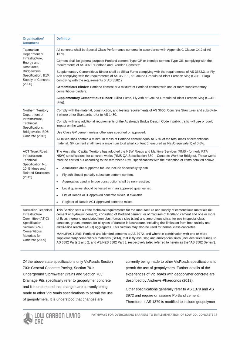
Tasmanian Department of Infrastructure, Energy and Resources, Bridgeworks Specification, B10: Supply of Concrete (2006)
All concrete shall be Special Class Performance concrete in accordance with Appendix C Clause C4.2 of AS 1379.
Cement shall be general purpose Portland cement Type GP or blended cement Type GB, complying with the requirements of AS 3972 "Portland and Blended Cements".
Supplementary Cementitious Binder shall be Silica Fume complying with the requirements of AS 3582.3, or Fly Ash complying with the requirements of AS 3582.1, or Ground Granulated Blast Furnace Slag (GGBF Slag) complying with the requirements of AS 3582.2
Cementitious Binder: Portland cement or a mixture of Portland cement with one or more supplementary cementitious binders.
Supplementary Cementitious Binder: Silica Fume, Fly Ash or Ground Granulated Blast Furnace Slag (GGBF Slag).
Northern Territory Department of Infrastructure, Technical Specifications, Bridgeworks, B06: Concrete (2012)
Comply with the material, construction, and testing requirements of AS 3600: Concrete Structures and substitute it where other Standards refer to AS 1480.
Comply with any additional requirements of the Austroads Bridge Design Code if public traffic will use or could impact on the works.
Use Class GP cement unless otherwise specified or approved.
All mixes shall contain a minimum mass of Portland cement equal to 55% of the total mass of cementitious material. GP cement shall have a maximum total alkali content (measured as Na2O equivalent) of 0.6%.
ACT Trunk Road Infrastructure Technical Specification No. 10: Bridges and Related Structures (2012)
The Australian Capital Territory has adopted the NSW Roads and Maritime Services (RMS - formerly RTA NSW) specifications for concrete works (RMS QA Specification B80 – Concrete Work for Bridges). These works must be carried out according to the referenced RMS specifications with the exception of items detailed below:
• Admixtures are supported for use include specifically fly ash
• Fly ash should partially substitute cement content.
• Aggregates used in bridge construction shall be non-reactive.
• Local quarries should be tested or in an approved quarries list.
• List of Roads ACT approved concrete mixes, if available.
• Register of Roads ACT approved concrete mixes.
Australian Technical Infrastructure Committee (ATIC) Specification Section SP43: Cementitious Materials for Concrete (2009)
This Section sets out the technical requirements for the manufacture and supply of cementitious materials (ie: cement or hydraulic cement), consisting of Portland cement, or of mixtures of Portland cement and one or more of fly ash, ground granulated iron blast-furnace slag (slag) and amorphous silica, for use in special class concrete, grouts, mortars for all types of durable infrastructure, including risk limitation from both salinity and alkali-silica reactive (ASR) aggregates. This Section may also be used for normal class concretes.
MANUFACTURE: Portland and blended cements to AS 3972, and where in combination with one or more supplementary cementitious materials (SCM), that is fly ash, slag and amorphous silica (includes silica fume), to AS 3582 Parts 1 and 2, and AS/NZS 3582 Part 3, respectively (also referred to herein as the “AS 3582 Series”).
Of the above state specifications only VicRoads Section
703: General Concrete Paving, Section 701:
Underground Stormwater Drains and Section 705:
Drainage Pits specifically refer to geopolymer concrete
and it is understood that changes are currently being
made to other VicRoads specifications to permit the use
of geopolymers. It is understood that changes are
currently being made to other VicRoads specifications to
permit the use of geopolymers. Further details of the
experiences of VicRoads with geopolymer concrete are
described by Andrews-Phaedonos (2012).
Other specifications generally refer to AS 1379 and AS
3972 and require or assume Portland cement.
Therefore, if AS 1379 is modified to include geopolymer
PATHWAYS FOR OVERCOMING BARRIERS TO IMPLEMENTATION OF LOW CO2 CONCRETE 16

concrete this will assist in adoption at a state level.
Modification of existing state specifications as has been
performed by VicRoads would also create a pathway for
use and greater adoption of geopolymer concrete.
PATHWAYS FOR OVERCOMING BARRIERS TO IMPLEMENTATION OF LOW CO2 CONCRETE 17
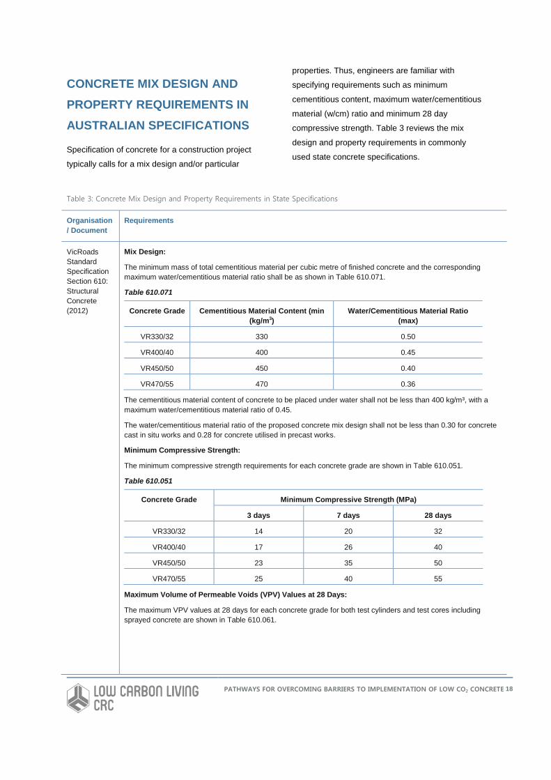
CONCRETE MIX DESIGN AND PROPERTY REQUIREMENTS IN AUSTRALIAN SPECIFICATIONS
Specification of concrete for a construction project
typically calls for a mix design and/or particular
properties. Thus, engineers are familiar with
specifying requirements such as minimum
cementitious content, maximum water/cementitious
material (w/cm) ratio and minimum 28 day
compressive strength. Table 3 reviews the mix
design and property requirements in commonly
used state concrete specifications.
Table 3: Concrete Mix Design and Property Requirements in State Specifications
Organisation/ Document
Requirements
VicRoads Standard Specification Section 610: Structural Concrete (2012)
Mix Design:
The minimum mass of total cementitious material per cubic metre of finished concrete and the corresponding maximum water/cementitious material ratio shall be as shown in Table 610.071.
Table 610.071
Concrete Grade Cementitious Material Content (min (kg/m3)
Water/Cementitious Material Ratio (max)
VR330/32 330 0.50
VR400/40 400 0.45
VR450/50 450 0.40
VR470/55 470 0.36
The cementitious material content of concrete to be placed under water shall not be less than 400 kg/m³, with a maximum water/cementitious material ratio of 0.45.
The water/cementitious material ratio of the proposed concrete mix design shall not be less than 0.30 for concrete cast in situ works and 0.28 for concrete utilised in precast works.
Minimum Compressive Strength:
The minimum compressive strength requirements for each concrete grade are shown in Table 610.051.
Table 610.051
Concrete Grade Minimum Compressive Strength (MPa)
3 days 7 days 28 days
VR330/32 14 20 32
VR400/40 17 26 40
VR450/50 23 35 50
VR470/55 25 40 55
Maximum Volume of Permeable Voids (VPV) Values at 28 Days:
The maximum VPV values at 28 days for each concrete grade for both test cylinders and test cores including sprayed concrete are shown in Table 610.061.
PATHWAYS FOR OVERCOMING BARRIERS TO IMPLEMENTATION OF LOW CO2 CONCRETE 18
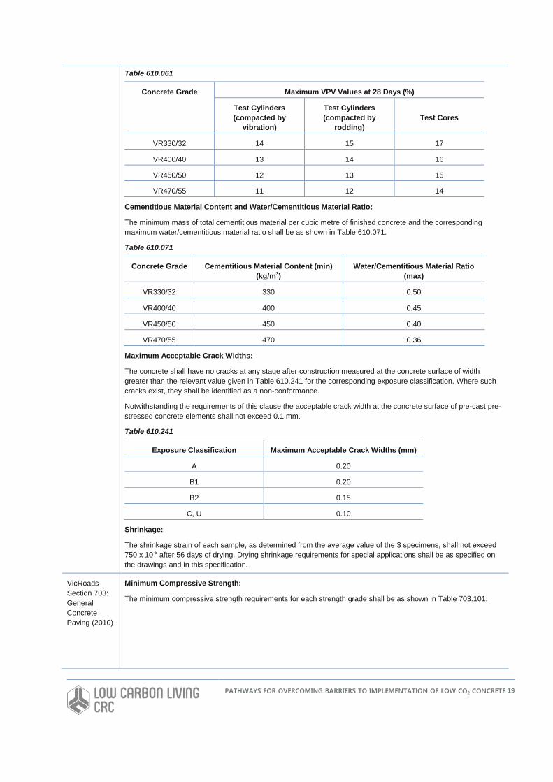
Table 610.061
Concrete Grade Maximum VPV Values at 28 Days (%)
Test Cylinders (compacted by
vibration)
Test Cylinders (compacted by
rodding) Test Cores
VR330/32 14 15 17
VR400/40 13 14 16
VR450/50 12 13 15
VR470/55 11 12 14
Cementitious Material Content and Water/Cementitious Material Ratio:
The minimum mass of total cementitious material per cubic metre of finished concrete and the corresponding maximum water/cementitious material ratio shall be as shown in Table 610.071.
Table 610.071
Concrete Grade Cementitious Material Content (min) (kg/m3)
Water/Cementitious Material Ratio (max)
VR330/32 330 0.50
VR400/40 400 0.45
VR450/50 450 0.40
VR470/55 470 0.36
Maximum Acceptable Crack Widths:
The concrete shall have no cracks at any stage after construction measured at the concrete surface of width greater than the relevant value given in Table 610.241 for the corresponding exposure classification. Where such cracks exist, they shall be identified as a non-conformance.
Notwithstanding the requirements of this clause the acceptable crack width at the concrete surface of pre-cast pre-stressed concrete elements shall not exceed 0.1 mm.
Table 610.241
Exposure Classification Maximum Acceptable Crack Widths (mm)
A 0.20
B1 0.20
B2 0.15
C, U 0.10
Shrinkage:
The shrinkage strain of each sample, as determined from the average value of the 3 specimens, shall not exceed 750 x 10-6 after 56 days of drying. Drying shrinkage requirements for special applications shall be as specified on the drawings and in this specification.
VicRoads Section 703: General Concrete Paving (2010)
Minimum Compressive Strength:
The minimum compressive strength requirements for each strength grade shall be as shown in Table 703.101.
PATHWAYS FOR OVERCOMING BARRIERS TO IMPLEMENTATION OF LOW CO2 CONCRETE 19
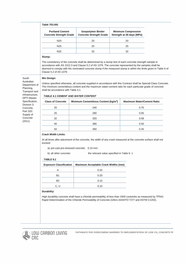
Table 703.091
Portland Cement Concrete Strength Grade
Geopolymer Binder Concrete Strength Grade
Minimum Compressive Strength at 28 days (MPa)
N20 20 20
N25 25 25
N32 32 32
Slump:
The consistency of the concrete shall be determined by a slump test of each concrete strength sample in accordance with AS 1012.3 and Clause 5.2 of AS 1379. The concrete represented by the samples shall be deemed to comply with the nominated concrete slump if the measured slump is within the limits given in Table 6 of Clause 5.2 of AS 1379.
South Australian Department of Planning, Transport and Infrastructure, DPTI Master Specification, Division 3: Concrete, Part 320: Supply of Concrete (2011)
Mix Design:
Unless specified otherwise, all concrete supplied in accordance with this Contract shall be Special-Class Concrete. The minimum cementitious content and the maximum water-cement ratio for each particular grade of concrete shall be accordance with Table 4.1.
TABLE 4.1 CEMENT AND WATER CONTENT
Class of Concrete Minimum Cementitious Content (kg/m3) Maximum Water/Cement Ratio
20 240 0.70
25 280 0.65
32 320 0.58
40 380 0.50
50 460 0.40
Crack Width Limits:
At all times after placement of the concrete, the width of any crack measured at the concrete surface shall not exceed:
a) pre-cast pre-stressed concrete: 0.10 mm;
b) all other concrete: the relevant value specified in Table 6. 1
TABLE 6.1
Exposure Classification Maximum Acceptable Crack Widths (mm)
A 0.20
B1 0.20
B2 0.15
C, U 0.10
Durability:
High durability concrete shall have a chloride permeability of less than 1500 coulombs as measured by TP541 Rapid Determination of the Chloride Permeability of Concrete (refers AASHTO T277 and ASTM C1202).
PATHWAYS FOR OVERCOMING BARRIERS TO IMPLEMENTATION OF LOW CO2 CONCRETE 20
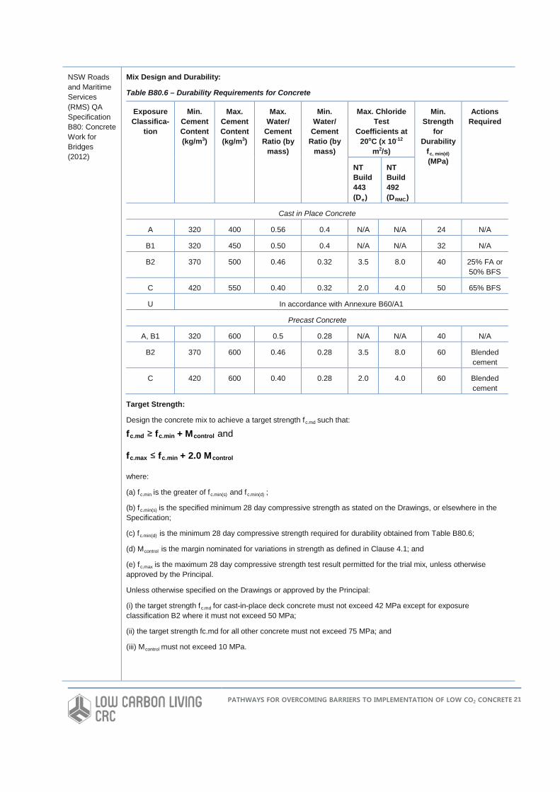
NSW Roads and Maritime Services (RMS) QA Specification B80: Concrete Work for Bridges (2012)
Mix Design and Durability:
Table B80.6 – Durability Requirements for Concrete
Exposure Classifica-
tion
Min. Cement Content (kg/m3)
Max. Cement Content (kg/m3)
Max. Water/
Cement Ratio (by
mass)
Min. Water/
Cement Ratio (by
mass)
Max. Chloride Test
Coefficients at 20oC (x 10-12
m2/s)
Min. Strength
for Durability
fc, min(d) (MPa)
Actions Required
NT Build 443 (De)
NT Build 492 (DRMC)
Cast in Place Concrete
A 320 400 0.56 0.4 N/A N/A 24 N/A
B1 320 450 0.50 0.4 N/A N/A 32 N/A
B2 370 500 0.46 0.32 3.5 8.0 40 25% FA or 50% BFS
C 420 550 0.40 0.32 2.0 4.0 50 65% BFS
U In accordance with Annexure B60/A1
Precast Concrete
A, B1 320 600 0.5 0.28 N/A N/A 40 N/A
B2 370 600 0.46 0.28 3.5 8.0 60 Blended cement
C 420 600 0.40 0.28 2.0 4.0 60 Blended cement
Target Strength:
Design the concrete mix to achieve a target strength fc.md such that:
fc.md ≥ fc.min + Mcontrol and
fc.max ≤ fc.min + 2.0 Mcontrol
where:
(a) fc.min is the greater of fc.min(s) and fc.min(d) ;
(b) fc.min(s) is the specified minimum 28 day compressive strength as stated on the Drawings, or elsewhere in the Specification;
(c) fc.min(d) is the minimum 28 day compressive strength required for durability obtained from Table B80.6;
(d) Mcontrol is the margin nominated for variations in strength as defined in Clause 4.1; and
(e) fc.max is the maximum 28 day compressive strength test result permitted for the trial mix, unless otherwise approved by the Principal.
Unless otherwise specified on the Drawings or approved by the Principal:
(i) the target strength fc.md for cast-in-place deck concrete must not exceed 42 MPa except for exposure classification B2 where it must not exceed 50 MPa;
(ii) the target strength fc.md for all other concrete must not exceed 75 MPa; and
(iii) Mcontrol must not exceed 10 MPa.
PATHWAYS FOR OVERCOMING BARRIERS TO IMPLEMENTATION OF LOW CO2 CONCRETE 21
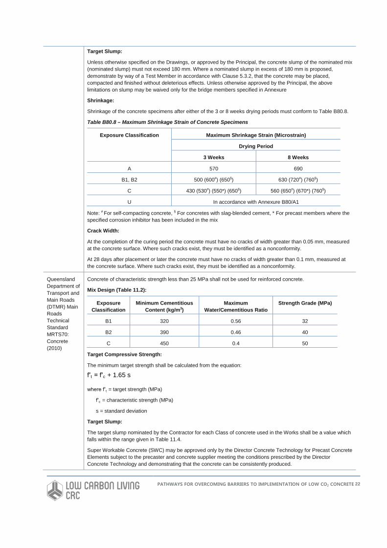
Target Slump:
Unless otherwise specified on the Drawings, or approved by the Principal, the concrete slump of the nominated mix (nominated slump) must not exceed 180 mm. Where a nominated slump in excess of 180 mm is proposed, demonstrate by way of a Test Member in accordance with Clause 5.3.2, that the concrete may be placed, compacted and finished without deleterious effects. Unless otherwise approved by the Principal, the above limitations on slump may be waived only for the bridge members specified in Annexure
Shrinkage:
Shrinkage of the concrete specimens after either of the 3 or 8 weeks drying periods must conform to Table B80.8.
Table B80.8 – Maximum Shrinkage Strain of Concrete Specimens
Exposure Classification Maximum Shrinkage Strain (Microstrain)
Drying Period
3 Weeks 8 Weeks
A 570 690
B1, B2 500 (600#) (650§) 630 (720#) (760§)
C 430 (530#) (550*) (650§) 560 (650#) (670*) (760§)
U In accordance with Annexure B80/A1
Note: # For self-compacting concrete, § For concretes with slag-blended cement, * For precast members where the specified corrosion inhibitor has been included in the mix
Crack Width:
At the completion of the curing period the concrete must have no cracks of width greater than 0.05 mm, measured at the concrete surface. Where such cracks exist, they must be identified as a nonconformity.
At 28 days after placement or later the concrete must have no cracks of width greater than 0.1 mm, measured at the concrete surface. Where such cracks exist, they must be identified as a nonconformity.
Queensland Department of Transport and Main Roads (DTMR) Main Roads Technical Standard MRTS70: Concrete (2010)
Concrete of characteristic strength less than 25 MPa shall not be used for reinforced concrete.
Mix Design (Table 11.2):
Exposure Classification
Minimum Cementitious Content (kg/m3)
Maximum Water/Cementitious Ratio
Strength Grade (MPa)
B1 320 0.56 32
B2 390 0.46 40
C 450 0.4 50
Target Compressive Strength:
The minimum target strength shall be calculated from the equation:
f′ t = f′c + 1.65 s
where f′ t = target strength (MPa)
f′c = characteristic strength (MPa)
s = standard deviation
Target Slump:
The target slump nominated by the Contractor for each Class of concrete used in the Works shall be a value which falls within the range given in Table 11.4.
Super Workable Concrete (SWC) may be approved only by the Director Concrete Technology for Precast Concrete Elements subject to the precaster and concrete supplier meeting the conditions prescribed by the Director Concrete Technology and demonstrating that the concrete can be consistently produced.
PATHWAYS FOR OVERCOMING BARRIERS TO IMPLEMENTATION OF LOW CO2 CONCRETE 22
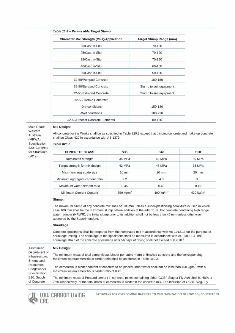
Table 11.4 – Permissible Target Slump
Characteristic Strength (MPa)/Application Target Slump Range (mm)
20/Cast In-Situ 70-120
25/Cast In-Situ 70-120
32/Cast In-Situ 70-150
40/Cast In-Situ 60-150
50/Cast In-Situ 50-150
32-50/Pumped Concrete 100-150
32-50/Sprayed Concrete Slump to suit equipment
32-50/Extruded Concrete Slump to suit equipment
32-50/Tremie Concrete:
-Dry conditions
-Wet conditions
150-180
180-220
32-50/Precast Concrete Elements 80-180
Main Roads Western Australia (MRWA) Specification 820: Concrete for Structures (2012)
Mix Design:
All concrete for the Works shall be as specified in Table 820.2 except that blinding concrete and make-up concrete shall be Class N20 in accordance with AS 1379.
Table 820.2
CONCRETE CLASS S35 S40 S50
Nominated strength 35 MPa 40 MPa 50 MPa
Target strength for mix design 42 MPa 48 MPa 58 MPa
Maximum aggregate size 10 mm 20 mm 20 mm
Minimum aggregate/cement ratio 3.2 4.0 3.0
Maximum water/cement ratio 0.45 0.43 0.40
Minimum Cement Content 350 kg/m3 400 kg/m3 420 kg/m3
Slump:
The maximum slump of any concrete mix shall be 100mm unless a super-plasticising admixture is used in which case 100 mm shall be the maximum slump before addition of the admixture. For concrete containing high range water reducer (HRWR), the initial slump prior to its addition shall not be less than 40 mm unless otherwise approved by the Superintendent.
Shrinkage:
Concrete specimens shall be prepared from the nominated mix in accordance with AS 1012.13 for the purpose of shrinkage testing. The shrinkage of the specimens shall be measured in accordance with AS 1012.13. The shrinkage strain of the concrete specimens after 56 days of drying shall not exceed 600 x 10-6.
Tasmanian Department of Infrastructure, Energy and Resources, Bridgeworks Specification, B10: Supply of Concrete
Mix Design:
The minimum mass of total cementitious binder per cubic metre of finished concrete and the corresponding maximum water/cementitious binder ratio shall be as shown in Table B10.2.
The cementitious binder content of concrete to be placed under water shall not be less than 400 kg/m3, with a
maximum water/cementitious binder ratio of 0.45.
The minimum mass of Portland cement in concrete mixes containing either GGBF Slag or Fly Ash shall be 60% or 75% respectively, of the total mass of cementitious binder in the concrete mix. The inclusion of GGBF Slag, Fly
PATHWAYS FOR OVERCOMING BARRIERS TO IMPLEMENTATION OF LOW CO2 CONCRETE 23

(2006) Ash or Silica Fume in concrete mixes shall be in binary or ternary combination with Portland cement.
In no case shall more than 40 kg/m3 of silica fume be added.
Where required by the Project Specification samples of concrete design mix shall be taken and tested in accordance with the relevant standard test methods for VPV. The maximum VPV values at 28 days for each concrete grade are shown in Table B10.2
Standard grades are shown in Table B10.2.
Table B10.2
Grade (f’c) Minimum Cementitious Binder (kg/m3)
Maximum Water/Cementitious Binder Ratio
Maximum VPV at 28 days (%) Test cylinders
S15 200 0.9
S20 260 0.75
S25 350 0.55
S32 400 0.5 15
S40 440 0.45 14
S50 470 0.4 13
S55 500 0.36 12
Compressive Strength:
The characteristic compressive strength of concrete (f'c) shall be determined at 28 days after placing by tests carried out on standard test specimens made, cured and tested in accordance with AS 1379 Appendix B Clause 3.4 and AS 1012:8 and 9.
Slump:
The slump shall be 60 mm + 15 or within the range nominated in the Mix Design for concrete containing superplasticiser.
Northern Territory Department of Infrastructure, Technical Specifications, Bridgeworks, B06: Concrete (2012)
Mix Design:
Use concrete which is normal grade except where the durability requirements dictate more stringent cement contents and water/cement ratios.
The minimum cementitious content and maximum water/cementitious ratio shall be as shown in the table below:
Minimum Cement Proportions for Durability and Strength
Exposure Classification* Minimum Cement Content (kg/m3) Maximum Water/Cement Ratio
B1 320 0.56
B2 390 0.46
C 450 0.40
* As defined in AS 3600.
Minimum Compressive Strength:
The minimum target strength shall be calculated from the equation:
f’t = f’c +1.65s where f′ t = target strength (MPa)
f′c = characteristic strength (MPa)
s = standard deviation
Slump:
PATHWAYS FOR OVERCOMING BARRIERS TO IMPLEMENTATION OF LOW CO2 CONCRETE 24
The slump determined on the site in accordance with AS1012, Part 3 shall lie within the range established using the approved slump and tolerances specified in Table 6 of AS 1379.
Shrinkage:
Where specified, use shrinkage compensated concrete to entirely counteract long term shrinkage assuming that ordinary concrete exhibits 500 microstrain shrinkage.
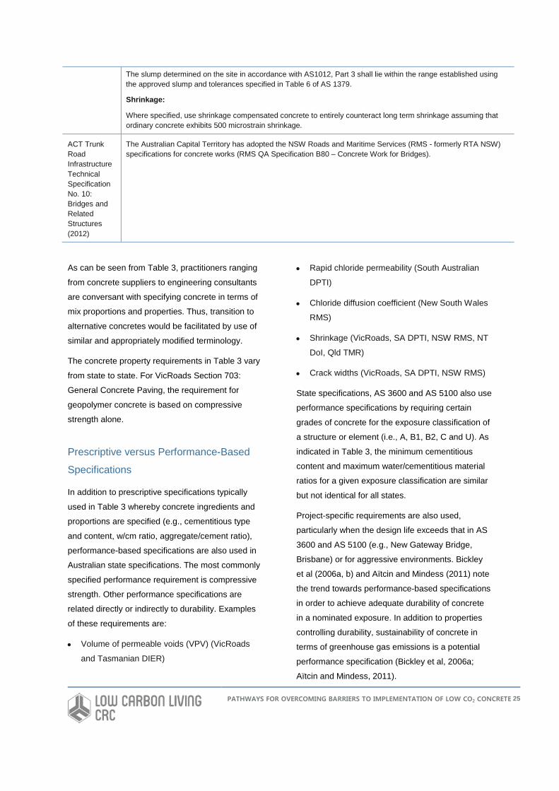
ACT Trunk Road Infrastructure Technical Specification No. 10: Bridges and Related Structures (2012)
The Australian Capital Territory has adopted the NSW Roads and Maritime Services (RMS - formerly RTA NSW) specifications for concrete works (RMS QA Specification B80 – Concrete Work for Bridges).
As can be seen from Table 3, practitioners ranging
from concrete suppliers to engineering consultants
are conversant with specifying concrete in terms of
mix proportions and properties. Thus, transition to
alternative concretes would be facilitated by use of
similar and appropriately modified terminology.
The concrete property requirements in Table 3 vary
from state to state. For VicRoads Section 703:
General Concrete Paving, the requirement for
geopolymer concrete is based on compressive
strength alone.
Prescriptive versus Performance-Based
Specifications
In addition to prescriptive specifications typically
used in Table 3 whereby concrete ingredients and
proportions are specified (e.g., cementitious type
and content, w/cm ratio, aggregate/cement ratio),
performance-based specifications are also used in
Australian state specifications. The most commonly
specified performance requirement is compressive
strength. Other performance specifications are
related directly or indirectly to durability. Examples
of these requirements are:
• Volume of permeable voids (VPV) (VicRoads
and Tasmanian DIER)
• Rapid chloride permeability (South Australian
DPTI)
• Chloride diffusion coefficient (New South Wales
RMS)
• Shrinkage (VicRoads, SA DPTI, NSW RMS, NT
DoI, Qld TMR)
• Crack widths (VicRoads, SA DPTI, NSW RMS)
State specifications, AS 3600 and AS 5100 also use
performance specifications by requiring certain
grades of concrete for the exposure classification of
a structure or element (i.e., A, B1, B2, C and U). As
indicated in Table 3, the minimum cementitious
content and maximum water/cementitious material
ratios for a given exposure classification are similar
but not identical for all states.
Project-specific requirements are also used,
particularly when the design life exceeds that in AS
3600 and AS 5100 (e.g., New Gateway Bridge,
Brisbane) or for aggressive environments. Bickley
et al (2006a, b) and Aïtcin and Mindess (2011) note
the trend towards performance-based specifications
in order to achieve adequate durability of concrete
in a nominated exposure. In addition to properties
controlling durability, sustainability of concrete in
terms of greenhouse gas emissions is a potential
performance specification (Bickley et al, 2006a;
Aïtcin and Mindess, 2011).
PATHWAYS FOR OVERCOMING BARRIERS TO IMPLEMENTATION OF LOW CO2 CONCRETE 25
Successful adoption of geopolymer concrete will
require a change of thinking from prescriptive
specification of conventional concrete mix
proportions to performance-based specifications. It
will also be necessary to determine what values of
particular properties are relevant for achieving
durability of geopolymer concrete. For example, a
maximum chloride diffusion coefficient of 2.0 x 10⁻¹²
m2/s specified to achieve a design life in a marine
environment controlled by reinforcement corrosion
may not necessarily be directly applicable to
geopolymer concrete. This would be the case if the
threshold concentration of chloride ions required to
initiate corrosion of reinforcement differs between
Portland cement concrete and geopolymer
concrete. The concrete strength and depth of cover
requirements in atmospherically exposed concrete
in AS 3600 and AS 5100 are based on assumed
carbonation rates. If carbonation rates differ
significantly for geopolymer concrete then these
requirements may need modification. Similarly,
durability design often assumes a certain corrosion
rate of reinforcement and a corrosion propagation
period before cracking and spalling occur. If the
corrosion rates and fracture properties for
conventional and geopolymer concrete differ
substantially then current specified concrete quality
and cover requirements may not be valid.
Consequently, long-term properties and behaviour
of geopolymer concrete need to be understood and
defined to develop appropriate performance-based
specifications or modify existing specifications.
PATHWAYS FOR OVERCOMING BARRIERS TO IMPLEMENTATION OF LOW CO2 CONCRETE 26
PROPERTY REQUIREMENTS FOR CONCRETE IN AS 3600
Design of plain, reinforced and prestressed
concrete in codes and standards such as AS 3600
implicitly assume that the concrete is based on
Portland cement. Therefore, adoption of
geopolymer concrete will necessitate understanding
of behaviour and if there are any substantial
differences from current design standards. An
example of where design codes have been
developed to deal with alternative materials is ACI
440.1R-06 (Guide for the Design and Construction
of Structural Concrete Reinforced with Fiber
Reinforced Polymer Bars).
This section reviews the state of the art for concrete
design in Australia and identifies which properties
are relevant if current standards are to be modified
to include geopolymer concrete. The design
property requirements are covered in Section 3 of
AS 3600. These requirements are summarised
below. Further details are provided in the standard.
Characteristic Compressive Strength
The characteristic compressive strength of concrete
at 28 days (f′c) shall be either—
(a) taken as equal to the specified strength grade,
provided the appropriate curing is ensured and that
the concrete complies with AS 1379; or
(b) determined statistically from compressive
strength tests carried out in accordance with AS
1012.9.
The characteristic compressive strengths of the
standard strength grades are 20 MPa, 25 MPa, 32
MPa, 40 MPa, 50 MPa, 65 MPa, 80 MPa and 100
MPa.
Mean In-Situ Compressive Strength
In the absence of more accurate data, the mean
value of the in situ compressive strength (fcmi) shall
be taken as 90% of the mean value of the cylinder
strength (fcm) or shall be taken as those given in
Table 3.1.2 of AS 3600.
Tensile Strength
The uniaxial tensile strength (fct) is the maximum
stress that concrete can withstand when subjected
to uniaxial tension. The uniaxial tensile strength
shall be determined from either the measured
flexural tensile strength (fct.f) or from the measured
splitting tensile strength (fct.sp) using:
fct = 0.6fct.f or fct = 0.9fct.sp
where fct.f and fct.sp are determined statistically from:
(a) flexural strength tests carried out in accordance
with AS 1012.11; or
(b) indirect tensile strength tests carried out in
accordance with AS 1012.10, respectively.
In the absence of more accurate data, the
characteristic flexural tensile strength of concrete
(f′ct.f) and the characteristic uniaxial tensile strength
of concrete (f’ct) shall be taken as:
𝑓𝑓′𝑐𝑐𝑐𝑐.𝑓𝑓 = 0.6�𝑓𝑓′ 𝑐𝑐 and 𝑓𝑓′𝑐𝑐𝑐𝑐 = 0.36�𝑓𝑓′ 𝑐𝑐 at 28 days and
standard curing, and where the mean and upper
characteristic values are obtained by multiplying
these values by 1.4 and 1.8, respectively.
Modulus of Elasticity
The mean modulus of elasticity of concrete at the
appropriate age (Ecj) shall be either:
(a) taken as equal to:
i. (𝜌𝜌1.5)×(0.043�𝑓𝑓𝑐𝑐𝑐𝑐𝑐𝑐) (in megapascals) when
fcmi ≤ 40 MPa; or
PATHWAYS FOR OVERCOMING BARRIERS TO IMPLEMENTATION OF LOW CO2 CONCRETE 27
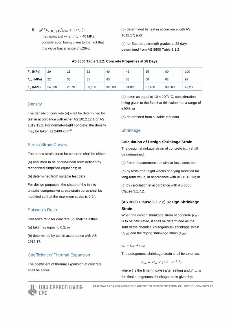
ii. (𝜌𝜌1.5)×(0.024�𝑓𝑓𝑐𝑐𝑐𝑐𝑐𝑐 + 0.12) (in
megapascals) when fcmi > 40 MPa,
consideration being given to the fact that
this value has a range of ±20%;
(b) determined by test in accordance with AS
1012.17; and
(c) for Standard strength grades at 28 days
determined from AS 3600 Table 3.1.2
AS 3600 Table 3.1.2: Concrete Properties at 28 Days
f’c (MPa) 20 25 32 40 45 65 80 100
fcmi (MPa) 22 38 35 43 53 68 82 99
Ec (MPa) 24,000 26,700 30,100 32,800 34,800 37,400 39,600 42,200
Density
The density of concrete (ρ) shall be determined by
test in accordance with either AS 1012.12.1 or AS
1012.12.2. For normal-weight concrete, the density
may be taken as 2400 kg/m3.
Stress-Strain Curves
The stress-strain curve for concrete shall be either:
(a) assumed to be of curvilinear form defined by
recognised simplified equations; or
(b) determined from suitable test data.
For design purposes, the shape of the in situ
uniaxial compressive stress-strain curve shall be
modified so that the maximum stress is 0.9f′c.
Poisson’s Ratio
Poisson’s ratio for concrete (ν) shall be either:
(a) taken as equal to 0.2; or
(b) determined by test in accordance with AS
1012.17.
Coefficient of Thermal Expansion
The coefficient of thermal expansion of concrete
shall be either:
(a) taken as equal to 10 × 10−6/°C, consideration
being given to the fact that this value has a range of
±20%; or
(b) determined from suitable test data.
Shrinkage
Calculation of Design Shrinkage Strain The design shrinkage strain of concrete (εcs) shall
be determined:
(a) from measurements on similar local concrete;
(b) by tests after eight weeks of drying modified for
long-term value, in accordance with AS 1012.13; or
(c) by calculation in accordance with AS 3600
Clause 3.1.7.2.
(AS 3600 Clause 3.1.7.2) Design Shrinkage Strain When the design shrinkage strain of concrete (εcs)
is to be calculated, it shall be determined as the
sum of the chemical (autogenous) shrinkage strain
(εcse) and the drying shrinkage strain (εcsd):
εcs = εcse + εcsd
The autogenous shrinkage strain shall be taken as:
𝜀𝜀𝑐𝑐𝑐𝑐𝑐𝑐 = 𝜀𝜀𝑐𝑐𝑐𝑐𝑐𝑐∗ × (1.0 − 𝑒𝑒−0.1𝑐𝑐)
where t is the time (in days) after setting and ε*cse is
the final autogenous shrinkage strain given by:
PATHWAYS FOR OVERCOMING BARRIERS TO IMPLEMENTATION OF LOW CO2 CONCRETE 28
𝜀𝜀𝑐𝑐𝑐𝑐𝑐𝑐∗ = (0.06𝑓𝑓𝑐𝑐′ − 1.0) × 50 × 10−6
At any time t (in days) after the commencement of
drying, the drying shrinkage strain shall be taken as:
𝜀𝜀𝑐𝑐𝑐𝑐𝑐𝑐 = 𝑘𝑘1𝑘𝑘4𝜀𝜀𝑐𝑐𝑐𝑐𝑐𝑐.𝑏𝑏
and k1 is obtained from Figure 3.1.7.2 in AS 3600
and k4 is equal to 0.7 for an arid environment, 0.65
for an interior environment, 0.6 for a temperate
inland environment and 0.5 for a tropical or near-
coastal environment.
The basic drying shrinkage strain (εcsd.b) is given by:
𝜀𝜀𝑐𝑐𝑐𝑐𝑐𝑐.𝑏𝑏 = (1.0 − 0.0008𝑓𝑓𝑐𝑐′) × 𝜀𝜀𝑐𝑐𝑐𝑐𝑐𝑐.𝑏𝑏∗
where the final drying basic shrinkage strain (ε*csd.b
) depends on the quality of the local aggregates and
shall be taken as 800 × 10−6 for Sydney and
Brisbane, 900 × 10−6 for Melbourne and 1000 × 10−6
elsewhere.
Further information is given in Table 3.1.7.2 of AS
3600.
Creep
The creep strain at any time (t) caused by a
constant sustained stress (σo) shall be calculated
from:
𝜀𝜀𝑐𝑐𝑐𝑐 = 𝜑𝜑𝑐𝑐𝑐𝑐𝜎𝜎/𝐸𝐸𝑐𝑐
where
Ec = mean modulus of elasticity of the concrete at
28 days
ϕcc = design creep coefficient at time (t) determined
in accordance with Clause 3.1.8.3 of AS 3600.
The basic creep coefficient of concrete (ϕcc.b) is the
mean value of the ratio of final creep strain to
elastic strain for a specimen loaded at 28 days
under a constant stress of 0.4f′c and shall be:
(a) determined from measurements on similar local
concrete; or
(b) determined by tests in accordance with AS
1012.16; or
(c) taken as the value given in Table 3.1.8.2 of AS
3600.
The design creep coefficient for concrete at any
time, t, (ϕcc) shall be determined from the basic
creep coefficient (ϕcc.b) by any accepted
mathematical model for creep behaviour, calibrated
such that ϕcc.b is also predicted by the chosen
model.
In the absence of more accurate methods, ϕcc at
any time shall be taken as:
ϕcc = k2k3k4k5ϕcc.b
where k2 and k3 are obtained from Figure
3.1.8.3(A) and Figure 3.1.8.3(B) of AS 3600
respectively; k4 = 0.70 for an arid environment, 0.65
for an interior environment, 0.60 for a temperate
inland environment and 0.50 for a tropical or near-
coastal environment; k5 is a modification factor for
high strength concrete and shall be taken as:
k5 = 1.0 when f’c ≤ 50 MPa;
or
k5 = (2.0 - α3) − 0.02(1.0−α3)f’c when 50 MPa < f’c ≤
100 MPa
The factor α3 = 0.7/(k4 α2); and α2 is defined as
Figure 3.1.8.3(A) in AS 3600.
Consideration shall be given to the fact that ϕcc has
a range of approximately ±30%. This range is likely
to be exceeded if:
(a) the concrete member is subjected to prolonged
periods of temperature in excess of 25°C; or
(b) the member is subject to sustained stress levels
in excess of 0.5f′cc.
The final design creep coefficients (ϕ*cc) (after 30
years) predicted by this method for concrete first
loaded at 28 days are given in Table 3.1.8.3 of AS
3600.
PATHWAYS FOR OVERCOMING BARRIERS TO IMPLEMENTATION OF LOW CO2 CONCRETE 29
Summary of AS 3600 Design
Requirements
Inclusion of geopolymer concrete in AS 3600 will
need knowledge on design properties if this material
is to be used in structural applications. Properties of
interest include:
• Compressive strength
• Tensile strength
• Modulus of elasticity
• Density
• Stress-strain curves
• Poisson’s ratio
• Coefficient of thermal expansion
• Shrinkage
• Creep
• Bond strength to reinforcement
Furthermore, durability properties such as chloride
diffusion coefficient, carbonation coefficient and
sulphate resistance require consideration in order to
comply with AS 3600 durability design.
Models predicting concrete behaviour are used
extensively in the design basis described in AS
3600 and it would be necessary to verify
applicability to geopolymer concrete or modify if
geopolymer concrete is to gain widespread
acceptance for structural use.
PATHWAYS FOR OVERCOMING BARRIERS TO IMPLEMENTATION OF LOW CO2 CONCRETE 30
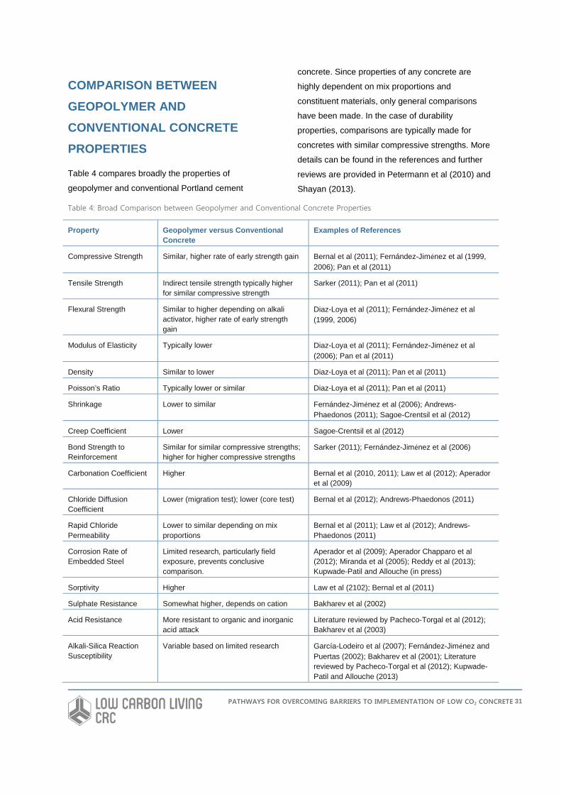
COMPARISON BETWEEN GEOPOLYMER AND CONVENTIONAL CONCRETE PROPERTIES
Table 4 compares broadly the properties of
geopolymer and conventional Portland cement
concrete. Since properties of any concrete are
highly dependent on mix proportions and
constituent materials, only general comparisons
have been made. In the case of durability
properties, comparisons are typically made for
concretes with similar compressive strengths. More
details can be found in the references and further
reviews are provided in Petermann et al (2010) and
Shayan (2013).
Table 4: Broad Comparison between Geopolymer and Conventional Concrete Properties
Property Geopolymer versus Conventional Concrete
Examples of References
Compressive Strength Similar, higher rate of early strength gain Bernal et al (2011); Fernández-Jiménez et al (1999, 2006); Pan et al (2011)
Tensile Strength Indirect tensile strength typically higher for similar compressive strength
Sarker (2011); Pan et al (2011)
Flexural Strength Similar to higher depending on alkali activator, higher rate of early strength gain
Diaz-Loya et al (2011); Fernández-Jiménez et al (1999, 2006)
Modulus of Elasticity Typically lower Diaz-Loya et al (2011); Fernández-Jiménez et al (2006); Pan et al (2011)
Density Similar to lower Diaz-Loya et al (2011); Pan et al (2011)
Poisson’s Ratio Typically lower or similar Diaz-Loya et al (2011); Pan et al (2011)
Shrinkage Lower to similar Fernández-Jiménez et al (2006); Andrews-Phaedonos (2011); Sagoe-Crentsil et al (2012)
Creep Coefficient Lower Sagoe-Crentsil et al (2012)
Bond Strength to Reinforcement
Similar for similar compressive strengths; higher for higher compressive strengths
Sarker (2011); Fernández-Jiménez et al (2006)
Carbonation Coefficient Higher Bernal et al (2010, 2011); Law et al (2012); Aperador et al (2009)
Chloride Diffusion Coefficient
Lower (migration test); lower (core test) Bernal et al (2012); Andrews-Phaedonos (2011)
Rapid Chloride Permeability
Lower to similar depending on mix proportions
Bernal et al (2011); Law et al (2012); Andrews-Phaedonos (2011)
Corrosion Rate of Embedded Steel
Limited research, particularly field exposure, prevents conclusive comparison.
Aperador et al (2009); Aperador Chapparo et al (2012); Miranda et al (2005); Reddy et al (2013); Kupwade-Patil and Allouche (in press)
Sorptivity Higher Law et al (2102); Bernal et al (2011)
Sulphate Resistance Somewhat higher, depends on cation Bakharev et al (2002)
Acid Resistance More resistant to organic and inorganic acid attack
Literature reviewed by Pacheco-Torgal et al (2012); Bakharev et al (2003)
Alkali-Silica Reaction Susceptibility
Variable based on limited research García-Lodeiro et al (2007); Fernández-Jiménez and Puertas (2002); Bakharev et al (2001); Literature reviewed by Pacheco-Torgal et al (2012); Kupwade-Patil and Allouche (2013)
PATHWAYS FOR OVERCOMING BARRIERS TO IMPLEMENTATION OF LOW CO2 CONCRETE 31
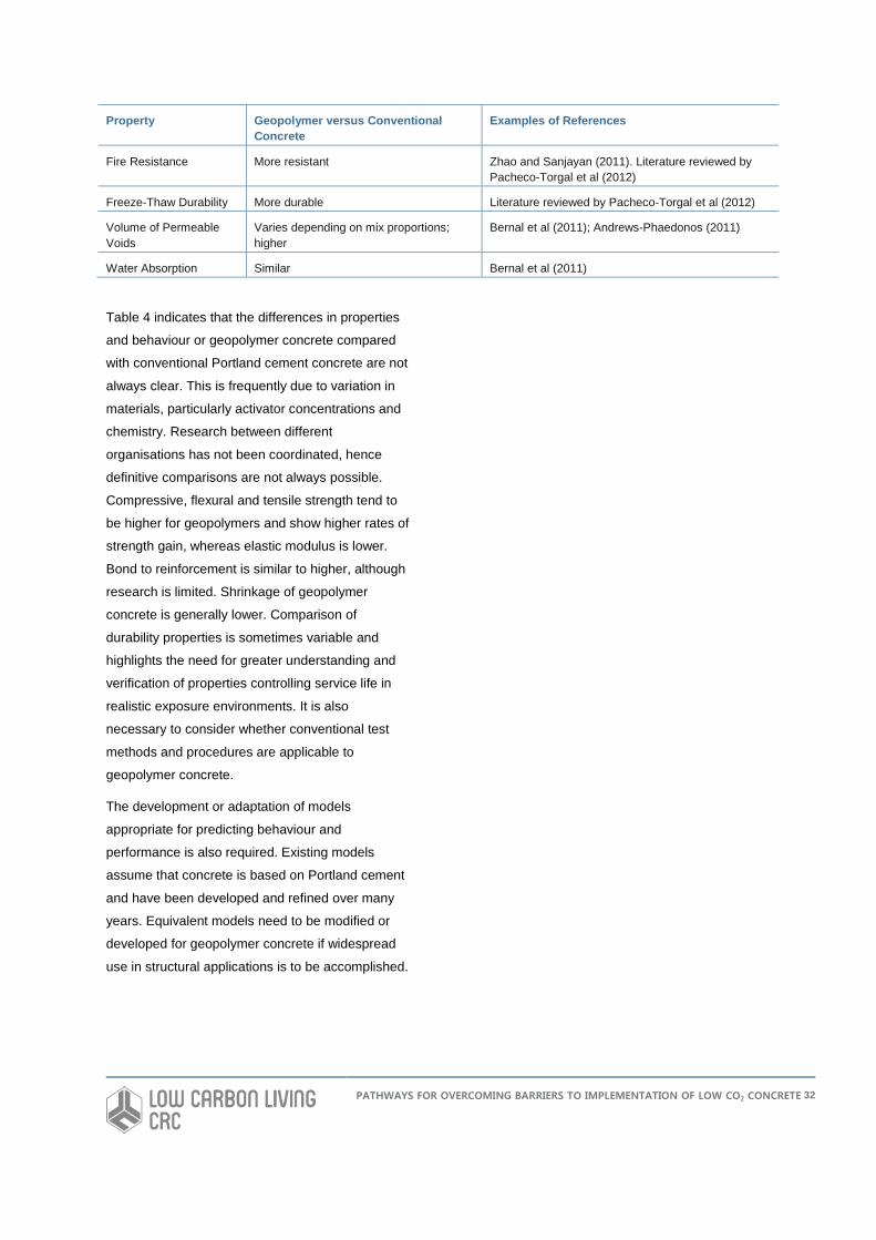
Property Geopolymer versus Conventional Concrete
Examples of References
Fire Resistance More resistant Zhao and Sanjayan (2011). Literature reviewed by Pacheco-Torgal et al (2012)
Freeze-Thaw Durability More durable Literature reviewed by Pacheco-Torgal et al (2012)
Volume of Permeable Voids
Varies depending on mix proportions; higher
Bernal et al (2011); Andrews-Phaedonos (2011)
Water Absorption Similar Bernal et al (2011)
Table 4 indicates that the differences in properties
and behaviour or geopolymer concrete compared
with conventional Portland cement concrete are not
always clear. This is frequently due to variation in
materials, particularly activator concentrations and
chemistry. Research between different
organisations has not been coordinated, hence
definitive comparisons are not always possible.
Compressive, flexural and tensile strength tend to
be higher for geopolymers and show higher rates of
strength gain, whereas elastic modulus is lower.
Bond to reinforcement is similar to higher, although
research is limited. Shrinkage of geopolymer
concrete is generally lower. Comparison of
durability properties is sometimes variable and
highlights the need for greater understanding and
verification of properties controlling service life in
realistic exposure environments. It is also
necessary to consider whether conventional test
methods and procedures are applicable to
geopolymer concrete.
The development or adaptation of models
appropriate for predicting behaviour and
performance is also required. Existing models
assume that concrete is based on Portland cement
and have been developed and refined over many
years. Equivalent models need to be modified or
developed for geopolymer concrete if widespread
use in structural applications is to be accomplished.
PATHWAYS FOR OVERCOMING BARRIERS TO IMPLEMENTATION OF LOW CO2 CONCRETE 32
CURRENT DEVELOPMENTS IN RECOMMENDED PRACTICES AND STANDARDS FOR LOW CO2 CONCRETE
The majority of research and development on low CO2
concrete, particularly geopoymer concrete, is published
in journals and conference proceedings. There are
currently several activities and resources aimed at
disseminating practical information and developing
standards for geopolymer concrete. The Concrete
Institute of Australia (CIA) has produced a
recommended practice for geopolymer concrete (CIA,
2011). This document provides background information
on geopolymer chemistry and materials and properties
of geopolymer concrete. Recommendations on
modification to current standards are given.
RILEM Technical Committee 224-AAM on Alkali-
Activated Materials has an objective of developing
performance-based specifications and recommendations
for development of standards for these materials. The
scope includes alkali-activated slags and ashes,
geopolymer and other emerging technologies. The
Committee aims to deliver recommendations on
performance-based requirements for alkali-activated
materials which can be used by national Standards
bodies. It is expected that the committee will finalise a
document in 2013. The RILEM Committee also plans to
conduct a durability testing programme.
ASTM Committees C01 (Cement) and C09 (Concrete
and Concrete Aggregates) are considering standards for
non-Portland cement binders such as geopolymers and
related alkali-activated aluminosilicates. Such standards
should increase user confidence with these materials.
PATHWAYS FOR OVERCOMING BARRIERS TO IMPLEMENTATION OF LOW CO2 CONCRETE
33
BARRIERS TO IMPLEMENTATION OF GEOPOLYMER CONCRETE
Implementation of low CO2 concrete materials on a large
scale requires identification of barriers to use. Adoption
of new or different materials in the construction and
other industries also face barriers and examination of
these is relevant. Barriers considered for geopolymer
concrete and new materials in general are discussed in
this section.
Geopolymer Specific Barriers
Several authors have highlighted technical, regulatory,
economic and supply chain barriers specific to
widespread commercialisation of geopolymer concrete.
For example, van Deventer et al (2012) identified the
following barriers compared with concrete based on
ordinary Portland cement:
• Variability in source materials
• Development of suitable admixtures
• Required operator skill at batch plants
• Capital intensive set up of processing facilities
• Existing prescriptive standard framework based on
Portland cement binder rather than performance
• Lack of long-term durability data, particularly field
performance
• Development of appropriate tests methods
• Risk of supply chain issues such as reduced
availability of suitable fly ash and blast furnace slag
Duxson and Provis (2008) stated that “The main
impediment facing the uptake of new construction
materials is the existing standards regime, where
prescriptive standards specify particular mix designs for
concrete rather than allowing any material which meets
given performance standards to be utilised”.
Acceptance of geopolymer concrete was also
considered by Aldred and Day (2012), in addition to
review of properties and case histories of use in
Australia. It was noted that the term “geopolymer” covers
a wide range of binder materials and, hence, wide
variation in properties and performance. This can be
confusing to designers and specifiers. The use of
prescriptive standards and codes and exclusion of non-
Portland cement binders in these regulations were
identified as an impediment to acceptance of
geopolymers.
Perera (2007) cited the following barriers for widespread
use of geopolymers:
• Conservatism of end user
• Lack of historical and long-term durability data
• Lack of investment in geopolymer plants
• Lack of pure precursors to study and improve
scientific understanding
• Variability
• Use of ambiguous terminology
RILEM Technical Committee 224-AAM has listed the
major obstacle hindering the widespread uptake of
alkali-activation technology in the construction industry
as the lack of uniformly accepted standards.
The Federal Highway Administration (FHWA) produced
a TechBrief on geopolymer concrete as part of the
Concrete Pavement Technology Program (FHWA,
2010). This document considered current limitations for
geopolymers as follows:
• Difficulty and care required in working with available
systems
• Safety risk associated with alkalinity of activating
solution
• Processing of high alkalinity solutions and associated
energy consumption and greenhouse gas generation
• Temperature sensitivity
• Elevated temperature curing under strict control
PATHWAYS FOR OVERCOMING BARRIERS TO IMPLEMENTATION OF LOW CO2 CONCRETE 34
It was suggested that geopolymer concrete in the
transportation industry is best suited to precast
applications until the above limitations are overcome.
In efforts to meet long-term CO2 reduction targets in
Europe, the Cement Sustainability Initiative investigated
a range of means of reducing emissions associated with
cement production (Cement Sustainability Initiative,
2009). Geopolymer binders were also considered and
barriers to implementation were listed as:
• Properties of geopolymer cement strongly depend on
the starting material. This can lead to variations in
the workability and other properties of the concrete
• Durability of the concrete has yet to be demonstrated
• Reactive components, like fly ash and slag, are
industrial waste products and their availability
depends on the future of coal fired power plants and
future steel production
• Operational safety working with highly alkaline
conditions has to be assured
• Production quantities and costs for the alkaline
activator (e.g., sodium silicate) will play an important
role in the production of geopolymer cements
Whilst geopolymer concrete offers potential benefits in
terms of greenhouse gas reduction compared with
Portland cement concrete, sustainability and reduced
emissions could be viewed as intangible. Improvement
in tangible properties such as cost, strength or durability
is likely to be more readily understood by end users than
greenhouse gas emissions.
Industry Survey on Barriers to Geopolymers
A survey consisting of six questions was proposed to
obtain input from representatives of the concrete and
affiliated industries. Participants were asked to identify
barriers to the implementation of geopolymer concrete
and determine potential pathways for overcoming these
barriers. The survey questions are presented below.
Q1. What is your primary role? (Tick one only)
Engineering consultant
Academic/Research
Government
Contractor
Material supplier
Industry association
Designer/Architect
Sales/Marketing
Other
Q2. What is your familiarity with geopolymer
concrete?
None at all
A little knowledge
Moderate knowledge
Detailed knowledge
Q3. What do you think are the barriers to widespread
implementation of geopolymer concrete? (Tick all that
apply)
Lack of awareness
Lack of industry guidelines or recommended
practices
Lack or standard specifications
Lack of education and training
Lack of demand
Geopolymer concrete is not covered in
existing Australian Standards (e.g., AS 3600)
Geopolymer concrete is not covered in state
or local specifications
Cost
Proprietary formulations
Lack of long-term performance data
Constructability or productivity issues
Risk/liability
PATHWAYS FOR OVERCOMING BARRIERS TO IMPLEMENTATION OF LOW CO2 CONCRETE 35
Supply chain or availability issues
Safety during production
Contractual issues
Other (please add comments)
Q4. What actions do you think should be taken to
overcome the barriers to implementation of geopolymer
concrete? (Tick all that apply)
Seminars and workforce training
Development of standard specifications
Modification of existing design methods
Modification of existing Australian Standards
for concrete to include geopolymers
Development of new Australian Standards
specific to geopolymer concrete
Development of performance-based
standards
Provision for use of geopolymer concrete in
state and local specifications and contracts
Financial incentives
Greater recognition of Green Star, LEED or
similar environmental reward schemes
Cost competitive with conventional concrete
More research on engineering properties and
long-term durability
More field demonstrations
Use of inspection and non-destructive testing
or sensors to monitor in-situ performance
Development of risk management and
assignment strategies
Increased availability of suitable products
Improved safety
Other (please comment)
Q5. What applications do you think offer the highest
volume use of geopolymer concrete in the near future?
(Tick all that apply)
Precast
Non-structural
Structural
Footpaths and bike or shared paths
Residential slabs and driveways
Industrial slabs (e.g., warehouses)
Roads
Pipes
Railway sleepers
No-fines (pervious) concrete
Fire resistant applications (e.g., tunnel linings)
Chemical resistant applications (e.g., acid
bunds, sewers)
Stabilisation of hazardous waste
Bricks, masonry blocks
Other (please comment)
Q6. Do you have any other comments? (Please add)
Results of Industry Survey
There were 42 total respondents to the survey and 40-42
responses to each question. As shown in Figure 1, the
majority of survey respondents were material suppliers,
government, academic/researchers or engineering
consultants. A significant proportion of respondents were
in the “other” category. The roles of these people were
retired/author, asset manager, coal power generators
and construction materials consultant. Figure 2 indicates
that most respondents were knowledgeable on
geopolymer concrete to some degree and that the
majority had a moderate level of knowledge. The
responses to the question regarding barriers are
presented in Figure 3 and discussed in Section 9.4.
PATHWAYS FOR OVERCOMING BARRIERS TO IMPLEMENTATION OF LOW CO2 CONCRETE 36
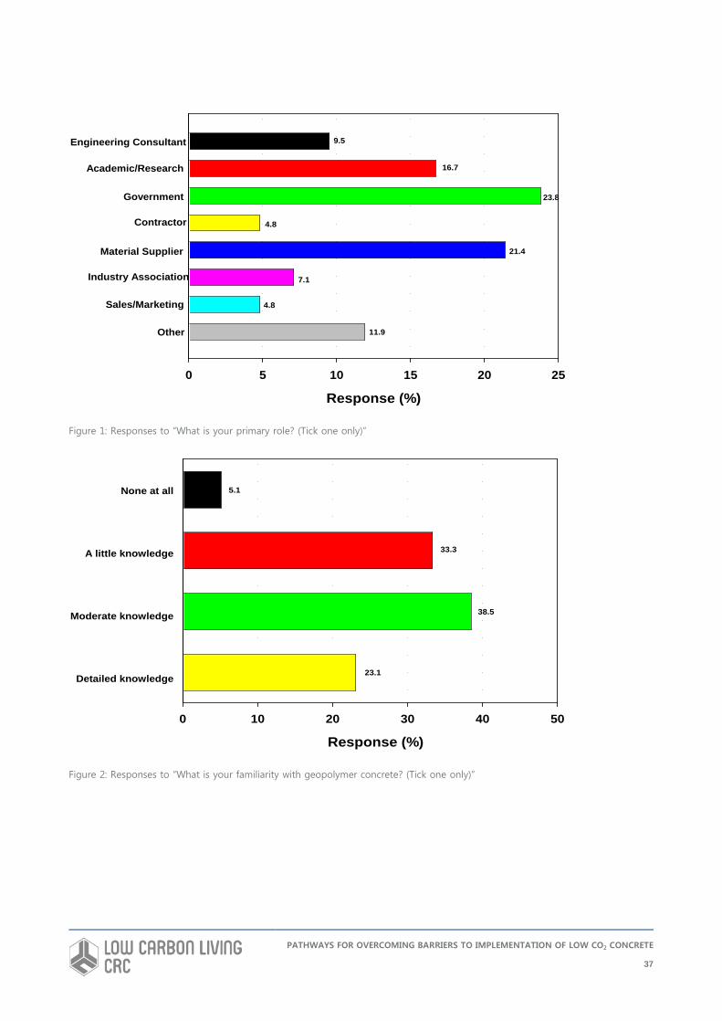
Figure 1: Responses to “What is your primary role? (Tick one only)”
Figure 2: Responses to “What is your familiarity with geopolymer concrete? (Tick one only)”
Response (%)
0 5 10 15 20 25
Engineering Consultant
Academic/Research
Government
Contractor
Material Supplier
Industry Association
Sales/Marketing
Other
9.5
16.7
23.8
4.8
21.4
7.1
4.8
11.9
Response (%)
0 10 20 30 40 50
None at all
A little knowledge
Moderate knowledge
Detailed knowledge
5.1
33.3
38.5
23.1
PATHWAYS FOR OVERCOMING BARRIERS TO IMPLEMENTATION OF LOW CO2 CONCRETE
37
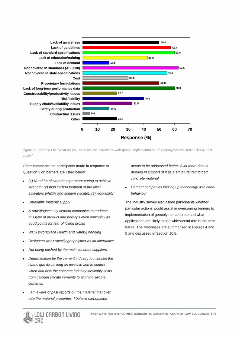
Figure 3: Responses to “What do you think are the barriers to widespread implementation of geopolymer concrete? (Tick all that
apply)”
Other comments the participants made in response to
Question 3 on barriers are listed below:
• (1) Need for elevated temperature curing to achieve
strength; (2) high carbon footprint of the alkali
activators (NaOH and sodium silicate); (3) workability
• Unreliable material supply
• A unwillingness by cement companies to endorse
this type of product and perhaps even downplay its
good points for fear of losing profits
• WHS (Workplace Health and Safety) handing
• Designers won't specify geopolymer as an alternative
• Not being pushed by the main concrete suppliers
• Determination by the cement industry to maintain the
status quo for as long as possible and to control
when and how the concrete industry inevitably shifts
from calcium silicate cements to alumino silicate
cements.
• I am aware of past reports on the material that over
rate the material properties. I believe carbonation
needs to be addressed better. A lot more data is
needed in support of it as a structural reinforced
concrete material
• Cement companies locking up technology with cartel
behaviour
The industry survey also asked participants whether
particular actions would assist in overcoming barriers to
implementation of geopolymer concrete and what
applications are likely to see widespread use in the near
future. The responses are summarised in Figures 4 and
5 and discussed in Section 10.5.
Response (%)
0 10 20 30 40 50 60 70
Lack of awarenessLack of guidelines
Lack of standard specificationsLack of education/training
Lack of demandNot covered in standards (AS 3600)Not covered in state specifications
CostProprietary formulations
Lack of long-term performance dataConstructability/productivity issues
Risk/liabilitySupply chain/availability issues
Safety during productionContractual issues
Other
50.0
57.560.0
42.517.5
62.5
55.0
30.0
50.0
60.0
22.5
40.0
32.5
17.55.0
22.5
PATHWAYS FOR OVERCOMING BARRIERS TO IMPLEMENTATION OF LOW CO2 CONCRETE 38
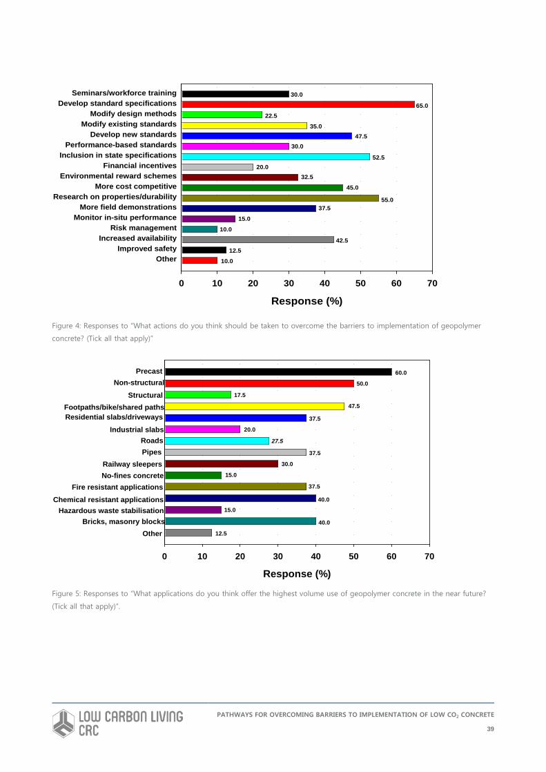
Figure 4: Responses to “What actions do you think should be taken to overcome the barriers to implementation of geopolymer
concrete? (Tick all that apply)”
Figure 5: Responses to “What applications do you think offer the highest volume use of geopolymer concrete in the near future?
(Tick all that apply)”.
Response (%)
0 10 20 30 40 50 60 70
Seminars/workforce trainingDevelop standard specifications
Modify design methodsModify existing standards
Develop new standardsPerformance-based standards
Inclusion in state specificationsFinancial incentives
Environmental reward schemesMore cost competitive
Research on properties/durabilityMore field demonstrations
Monitor in-situ performanceRisk management
Increased availabilityImproved safety
Other
30.0
65.022.5
35.047.5
30.0
52.520.0
32.5
45.0
55.037.5
15.0
10.0
42.512.5
10.0
Response (%)
0 10 20 30 40 50 60 70
PrecastNon-structural
StructuralFootpaths/bike/shared pathsResidential slabs/driveways
Industrial slabsRoadsPipes
Railway sleepersNo-fines concrete
Fire resistant applicationsChemical resistant applications
Hazardous waste stabilisationBricks, masonry blocks
Other
60.0
50.0
17.5
47.5
37.5
20.0
27.5
37.5
30.0
15.0
37.5
40.0
15.0
40.0
12.5
PATHWAYS FOR OVERCOMING BARRIERS TO IMPLEMENTATION OF LOW CO2 CONCRETE
39
Other responses to Question 4 on actions to overcome
barriers included:
• Program to help develop product on a site by site
basis
• Remove trademarks and patents - share IP
(Intellectual Property), partner with SRAs (Sponsored
Research Agreements)
• Independent research by people without an interest
in the material - people who don't want to "gild the
lily"
• Demonstrate/trial the use of in low risk applications -
walkways, footpaths, retaining walls
Additional comments in response to Question 5 on
highest volume applications in the near future included:
• Mine backfill
• Sewerage infrastructure (pipes, manholes, digestion
tanks)
• I don't know enough about the volume of available
applications to offer comments on the other options.
• School/Government Buildings and infrastructure
Respondents were asked to provide any additional
comments in Question 6. Responses received are as
follows:
• Development of niche markets where there is a
technical advantage over Portland cement and
blended cement concrete
• The possibility that by-products such as blast furnace
slag and fly ash from power stations will be used,
e.g., for geopolymer concrete, roadbase depends on
local circumstances, e.g., access to market, cost of
competing materials, local knowledge. In view of this
it's difficult to see a common solution. My thinking is
that the organisations that produce the by-products
e.g., smelters and power companies are generally
rich. In view of this they have the resources to
investigate the best (and most profitable) use of their
waste and should be pressured and encouraged to
do so.
• Need to consider supply, logistics, and other
components required for the manufacture
• The process to develop geopolymer concrete from fly
ash specific to individual power stations is going to
vary according to physical properties. The market
would develop quickly if the formula to make product
was available to all end users.
• I think we need to understand that geopolymer is not
a replacement for concrete. I think there a place for
both. Geopolymer by its nature requires for technical
assistance in preparation not like concrete which
every handyman can safely play with and come up
with a reasonable product. Hence I think the main
focus should be in other products which lend
themselves to QA control in a factory setting. Hence
blocks sleepers footpaths, special applications e.g.,
acid bunds etc
• Consolidate the warring factions - divided,
Geopolymer will fall!
• Intellectual Property and specification issues are a
significant barrier to moving forward.
• Governments need to push and customers need to
pull the demand for geopolymer concrete so that
industry can see its long term benefit as an
alternative (not a replacement) to OPC. The
pioneering work being done by Wagners in Qld
should be applauded by the industry!!
• I believe that it is inevitable that the concrete industry
will move to the use of alumino-silicate cements once
the cement industry gives in to community pressure
to reduce its carbon footprint. This transition will
probably take 20 or 30 years to complete and will
only be speeded up by community pressure,
authority acceptance and continued industrial
research.
• Being aware of a previous report produced
supposedly independently but which contained errors
and is guilty of "gilding the lily" and also aware of a
thesis from XXX University that also contained
errors, I feel I can't trust the literature that's being
PATHWAYS FOR OVERCOMING BARRIERS TO IMPLEMENTATION OF LOW CO2 CONCRETE
40
produced. The amount of data, level of detail of the
work performed, and accuracy of the data just aren't
sufficient at the present time, in my opinion, to
support the material being used for structural
applications. What's needed is very good quality
research by persons without any vested interests -
by persons who are more interested in producing
good research rather than promoting the product.
• Carbon footprint very high. Not really environmentally
friendly when proper life cycle analysis is performed.
Has a number of health and safety risks during
manufacture. Very costly.
• Happy to explore the use of Yallourn Ash in
Geopolymer development
Analysis of Barriers Identified in Industry
Survey
Respondents to the industry survey clearly identified the
lack of inclusion of geopolymer concrete in existing
Australian standards (e.g., AS 3600) and state or local
specifications and lack of industry guidelines or
recommended practices, lack of standard specifications,
and lack of education and training as significant barriers
(Figure 3). In particular, 62.5% of respondents rated the
absence of coverage in existing Australian standards as
the primary obstacle. Lack of long-term performance
data and lack of awareness were also significant.
Proprietary formulations were regarded as problematic
to widespread implementation. Risk/liability, supply chain
or availability issues and costs were considered as
barriers to a lesser, but still substantial, degree. Several
(17.5-22.5%) respondents rated constructability/
productivity issues and safety during production as
barriers. 22.5% of respondents added “Other” barriers
and these were related to material processing and
properties, carbon footprint of alkali activators, material
supply reliability, problems with cement companies and
concrete suppliers, handling, unwillingness of designers
to specify geopolymers, and conflicting, overrated and
insufficient property data. The responses to the question
regarding barriers distinctly demonstrate that there are
important issues and concerns that need to be
addressed if geopolymer concrete is to realise large-
scale use.
LinkedIn Survey on Geopolymer Concrete
In addition to the survey conducted under the CRC
project, an informal survey posed by the Cement,
Concrete and Construction discussion group on LinkedIn
(2013) asked the question “Will geopolymer binders be
the next best thing in construction?”. Of the 65
respondents, 41% voted “Yes”, 26% voted “Unsure”,
18% voted “No” and 13% indicated “I don’t know what
they are”. Barriers and potential pathways noted in the
LinkedIn survey comments included:
• Need for field versus laboratory data
• All mixes whether or not geopolymer should be the
result of extensive trial mixes by the producer and
initial supply to non-critical uses
• Less familiarity with geopolymer mixes requires more
caution than typical mixes
• Lack of standardised ingredients and procedures
• Conservatism of consultants and current codes of
practice
• Inconsistent data on CO2 savings
• Raw material availability
• Institutional barriers
• Health and safety issues with alkali activators
• Production needs to be well controlled, making it
more difficult and/or more expensive for mass
manufacturing
• The major issue is carbonation. Corrosion in
reinforced geopolymer concrete has not been
conclusively proved to be any lesser menace
compared to Portland cement concrete. Since the
major utilities of concrete are for building blocks or
reinforced concrete, geopolymer concrete needs
more studies. The aspects of plastic shrinkage and
rapid setting and development of suitable admixtures
PATHWAYS FOR OVERCOMING BARRIERS TO IMPLEMENTATION OF LOW CO2 CONCRETE 41
for tailoring the workability are real issues to be
answered.
• Let credible authorities use life cycle assessment to
determine the correct values of geopolymer concrete
versus OPC/SCM concrete, not the suppliers of the
materials
• Exploit those niche markets where enhanced
performance gives a market advantage rather than
replacing Portland cement
• Focus on precast that delivers final products first
Barriers to Other New or Sustainable
Materials in Construction
Lessons can also be learnt from introduction and
adoption of other new, alternative, innovative, more
sustainable and recycled materials to the conservative
construction industry. Such materials have faced similar
barriers and some published examples have been
reviewed.
The Transportation Research Board (TRB) produced a
research agenda for transportation infrastructure as a
conference outcome (TRB, 2009). One component of
the agenda was “Innovative Materials for Preservation,
Restoration, and Reconstruction”. With respect to
recycled and alternative materials, it was noted that
there the global trend towards sustainable infrastructure
requires increased use of these materials in
construction. However, despite the demand and wealth
of research and information, uptake on a large scale has
faced barriers. Cited impediments to high volume use of
recycled and alternative materials included (TRB, 2009;
Reid, 2002):
• Potential environmental impact
• Safety
• Constructability
• Lack of long-term performance data
• Lack of functional specifications and guidelines
• Lack of test methods
• Reliability and quality control issues
• Environmental concerns
• Waste regulations
• Conditions of contract
• Planning
• Supply and demand
• Economics
• Lack of awareness
The TRB agenda (TRB, 2009) also examined application
of innovative, advanced and smart materials in
transportation infrastructure. However, the potential
application areas were regarded as currently limited.
Costs, the highly risk averse nature of the transportation
infrastructure construction industry and the lack of
engagement in research has resulted in slow adoption of
new material technologies. It was pointed out that the
massive size and scale of the transportation industry
means that any improvement in materials performance
could result in significant economic impact.
A National Cooperative Highway Research Program
project identified “Implementation of the Use of New
Materials into Highway Construction Practice” as an area
requiring research (Russell et al, 2002). Identified
barriers to implementation included:
• Limited availability of long-term performance data
• Past unsuccessful experience with new materials
• High initial costs
• High risks
• Costs and time requirements of performance testing
to achieve acceptance by regulatory agencies
A study of sustainable practice and materials in the
Japanese Concrete Industry by Henry and Kato (2012).
Barriers identified are summarised in Table 5. These are
specific to Japan and may not necessarily be directly
applicable to Australia. However, the barriers are similar
to many of those for geopolymers and other new
materials.
PATHWAYS FOR OVERCOMING BARRIERS TO IMPLEMENTATION OF LOW CO2 CONCRETE 42
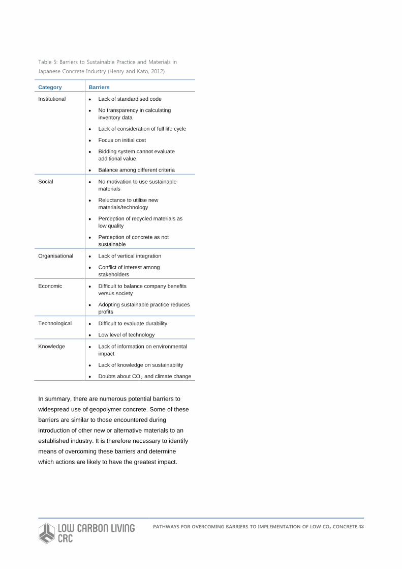
Table 5: Barriers to Sustainable Practice and Materials in
Japanese Concrete Industry (Henry and Kato, 2012)
Category Barriers
Institutional • Lack of standardised code
• No transparency in calculating inventory data
• Lack of consideration of full life cycle
• Focus on initial cost
• Bidding system cannot evaluate additional value
• Balance among different criteria
Social • No motivation to use sustainable materials
• Reluctance to utilise new materials/technology
• Perception of recycled materials as low quality
• Perception of concrete as not sustainable
Organisational • Lack of vertical integration
• Conflict of interest among stakeholders
Economic • Difficult to balance company benefits versus society
• Adopting sustainable practice reduces profits
Technological • Difficult to evaluate durability
• Low level of technology
Knowledge • Lack of information on environmental impact
• Lack of knowledge on sustainability
• Doubts about CO2 and climate change
In summary, there are numerous potential barriers to
widespread use of geopolymer concrete. Some of these
barriers are similar to those encountered during
introduction of other new or alternative materials to an
established industry. It is therefore necessary to identify
means of overcoming these barriers and determine
which actions are likely to have the greatest impact.
PATHWAYS FOR OVERCOMING BARRIERS TO IMPLEMENTATION OF LOW CO2 CONCRETE 43
POSSIBLE PATHWAYS FOR OVERCOMING BARRIERS Greater acceptance of geopolymer concrete requires
that concerns and issues are addressed in a thorough
and acceptable manner. The gap between research and
routine field use needs to be bridged.
Acceptance and Commercialisation of New
Materials
In discussion of new and innovative materials in general,
Maine et al (2005) noted the long period of gestation
(typically around 20 years) before widespread
acceptance and substitution. This includes materials
now in common use such as polyethylene. Maine et al
(2005) presented a methodology for viability analysis of
new materials including technical feasibility, production
cost modelling, value analysis and market assessment.
For materials proposed for substitution into a particular
application, performance and cost are key factors. For
materials with enhanced performance but higher costs or
vice versa, Maine et al (2005) suggested that
establishment of a market niche required information on
how the market values performance. In the case of
geopolymer concrete, this may require analysis of the
importance of greenhouse gas reduction to the
construction industry and greater dissemination of
potential benefits to end users.
Market assessment of new materials can follow two
broad strategies (Maine et al, 2005):
• Search for new markets or applications created by
the new material; or
• Explore substitution into existing markets
Substitution steps for new materials include: • Identify potential markets by comparing properties of
new material with existing materials and noting the
most promising property combinations of the new
material
• Identify size of potential markets
• Prioritise potential markets according to size and
type of substitution
• Assess utility of different markets and/or applications
for performance-cost attributes
• Use logistics curves to estimate time of market
penetration
• Choose toe-hold market for rollout
Future of Low CO2 Cements
In summarising the future of low CO2 cements, Gartner
(2004) stated the following: “Clearly, if any alternative
cementing system is ultimately to have a real impact on
global CO2 emissions related to the construction
industry, it will have to have performance and durability
characteristics at least as good as the current generation
of Portland-based cements, and probably even better,
because it is likely to be, at least initially, more
expensive to the consumer. The establishment of the
performance and durability of alternative cements and
concretes to the level required for the introduction of the
appropriate new standards and construction codes is
likely to be a very expensive undertaking because a
large number of tests (and committee meetings) will be
required. It will evidently require the full participation and
cooperation of industry, government, the scientific
community and members of the general public. It is only
by such a concerted effort that our society can hope to
bring about the long-term changes necessary to make
our built environment truly sustainable.”
The above statement is highly pertinent to geopolymer
concrete and emphasises key elements of performance
characteristics, appropriate standards and collaboration
required to gain widespread acceptance.
PATHWAYS FOR OVERCOMING BARRIERS TO IMPLEMENTATION OF LOW CO2 CONCRETE 44
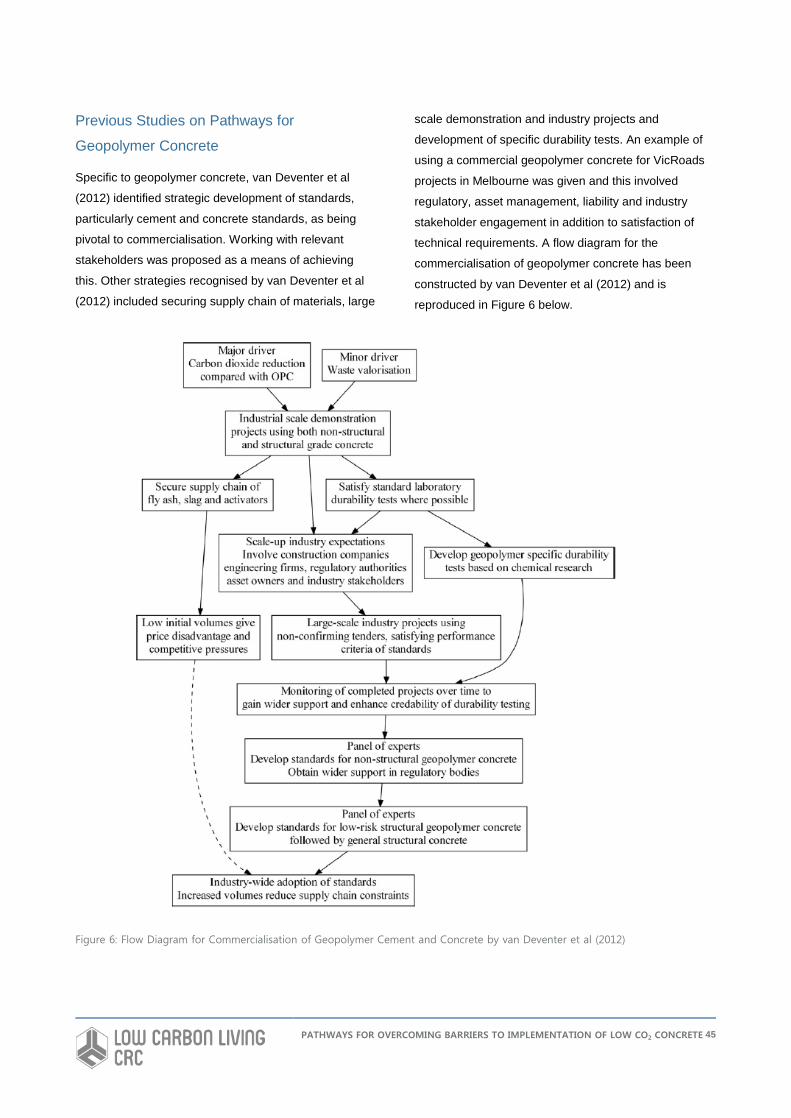
Previous Studies on Pathways for
Geopolymer Concrete
Specific to geopolymer concrete, van Deventer et al
(2012) identified strategic development of standards,
particularly cement and concrete standards, as being
pivotal to commercialisation. Working with relevant
stakeholders was proposed as a means of achieving
this. Other strategies recognised by van Deventer et al
(2012) included securing supply chain of materials, large
scale demonstration and industry projects and
development of specific durability tests. An example of
using a commercial geopolymer concrete for VicRoads
projects in Melbourne was given and this involved
regulatory, asset management, liability and industry
stakeholder engagement in addition to satisfaction of
technical requirements. A flow diagram for the
commercialisation of geopolymer concrete has been
constructed by van Deventer et al (2012) and is
reproduced in Figure 6 below.
Figure 6: Flow Diagram for Commercialisation of Geopolymer Cement and Concrete by van Deventer et al (2012)
PATHWAYS FOR OVERCOMING BARRIERS TO IMPLEMENTATION OF LOW CO2 CONCRETE 45
Duxson and Provis (2008) supported the development of
performance-based standards for greater acceptance of
low CO2 concrete in general. Acceptance by consulting
engineers was also regarded as important.
With respect to consulting engineers, architects and
clients may have interest in alternative concrete, but
approval by conservative and risk averse engineers can
prevent use in projects. This situation has been
encountered by the author on a number of major
projects where there has been a desire or requirement to
reduce greenhouse gas emissions and therefore
geopolymer concrete has been proposed for either
widespread or selected substitution for conventional
concrete. However, the perceived risks and liability of
using an alternative to Portland cement concrete,
particularly with regard to long-term performance,
typically result in geopolymer concrete only being used
for minor, non-structural applications, if at all. If
appropriate standards and specifications are developed
at state and national levels, in addition to long-term
durability data, then the obstacle presented by
consulting engineers could be overcome.
From technical and safety perspectives, the FHWA
(2010) suggested that low-alkali activating solutions and
curing in reasonable time under ambient conditions
would address barriers to use of geopolymer concrete.
The production of cost-effective geopolymer cements
that can be mixed and hardened essentially like Portland
cement was regarded as a “game changing”
advancement with potential for revolutionising
construction of transportation infrastructure.
Examples of Actions and Pathways for Other
Materials
The TRB research agenda (TRB, 2009) proposed
actions to address specific barriers to implementation of
new and innovative materials and technologies in the
transportation industry. These actions are also worth
consideration for overcoming barriers to use of
geopolymer concrete. Examples of actions include:
• Outreach to raise awareness
• Education
• Workforce training
• Improved strategies for workforce development
• Dissemination of best practices
• Application of existing standards for natural materials
to alternative materials
• Development of new or modified material, design
and construction standards and specifications
• Development of performance-based standards and
specifications
• Assess constructability using standard equipment
• Collect data and develop reliable life-cycle costs
• Develop inspection standards and policies
• Evaluate risk
• Risk assignment and management
• Risk based inspection
• Develop processes and policies for better decision
making
• Obtaining buy-in through demonstration, prototypes
and partnerships
• Continued development of infrastructure and
performance sensors
Polymer Concrete Two examples of new materials development in the
concrete field are polymer concrete and fibre reinforced
polymer (FRP) reinforcement. The pathways to use and
acceptance of these materials are relevant. Polymer
concrete, polymer impregnated concrete and polymer
modified concrete were the subject of extensive
research and development at Brookhaven National
Laboratory (BNL) from the mid-1960s until the late
1990s. This work, together with research at other
organisations, resulted in the development of
commercial products for numerous applications. The
ability to formulate polymer concrete from different resins
resulted in a wide range of properties and versatile uses.
PATHWAYS FOR OVERCOMING BARRIERS TO IMPLEMENTATION OF LOW CO2 CONCRETE 46
BNL’s work on polymer concrete included:
• Laboratory preparation and thorough testing of
different formulations for engineering, physical and
durability properties
• Evaluation of properties and identification of potential
applications
• Independent economic assessment
• Development of specific materials for a particular
need
• Scale-up and field demonstrations in collaboration
with regulatory agencies, industry partners and end-
users
• Monitoring of field demonstrations and evaluation of
material performance
• Development of user guidelines and specifications
• Testing to meet requirements of specific codes and
standards in order to demonstrate gain approval
• Technology transfer through publications, conference
presentations, field demonstrations, active
membership of technical committees, support and
training
• Technology transfer to commercial applicators
• Contribution to ACI Committee 548 and development
of ACI guidelines and specifications for polymer and
polymer modified concrete
The primary focus of research and development of
polymer concrete was applications where superior
performance compared with Portland cement concrete
could be readily achieved. Examples include durability in
aggressive environments, high temperature
performance, rapid setting, high strength, adhesion, low
permeability, wear resistance, versatility and aesthetics.
Owing to economics, polymer concrete cannot
realistically replace Portland cement concrete in
conventional construction. However, there is significant
demand for polymer concrete in precast applications,
overlays for concrete protection, concrete repair,
decorative floors and other specialised uses where
performance benefits or life-cycle costs outweigh initial
cost.
For geopolymer concrete, reduced greenhouse gas
emissions and improved performance in particular
applications are the key benefits. Unlike polymer
concrete, geopolymer concrete has the potential for
greater volume use, in addition to niche applications.
The approach used by BNL, other research institutions,
government organisations and private industry in the
development of polymer concrete show that
considerable effort and resources over a sustained
period of time are required to take a material from the
laboratory to widespread use and acceptance.
Fibre Reinforced Polymer Reinforcement Another example of introduction of a new material to an
established market is the use of fibre reinforced polymer
(FRP) reinforcement as an alternative to steel. The use
of FRP reinforcement in concrete is of growing interest
primarily due to its resistance to corrosion and damage
associated with steel reinforcement, especially in
aggressive environments. Owing to the relatively short
track record of FRP reinforcement in concrete compared
with conventional steel, questions arise as to its
performance and durability. Extensive research on the
performance of FRP has been conducted including
accelerated laboratory tests and monitored field
demonstrations to address raised concerns. This
research has focused on properties such as degradation
in alkaline environments, moisture absorption, creep,
relaxation, thermal behaviour, fire resistance, bond
strength, fatigue and behaviour of FRP reinforced
structures under static and dynamic loads.
Key to greater acceptance of FRP reinforcement has
been publication of research results, devoted conference
streams, field demonstrations involving collaboration
between research institutions and transportation
agencies, and production of informative reports,
specifications and design guidelines. In particular, ACI
Committee 440 has produced a number of documents
including ACI 440R-07 “State-of-the-Art Report on Fiber
Reinforced Plastic Reinforcement for Concrete
PATHWAYS FOR OVERCOMING BARRIERS TO IMPLEMENTATION OF LOW CO2 CONCRETE 47
Structures”, ACI 440.1R-06 “Guide for the Design and
Construction of Concrete Reinforced with FRP”, 440.3R-
04 “Guide Test Methods for Fiber-Reinforced Polymers
(FRPs) for Reinforcing or Strengthening Concrete
Structures”, and 440.5-08 “Specification for Construction
with Fiber-Reinforced Polymer Reinforcing Bars”. Design
guidelines for FRP reinforcement are also covered in
several international standards.
The example of how FRP reinforcement has overcome
barriers to acceptance highlights the necessity for
targeted research, engagement with regulatory agencies
and development of design standards, specifications and
guidelines. Similar actions, particularly on production of
standards, are required for greater adoption of
geopolymer concrete.
Pathways Identified in Industry Survey
The key action to overcome barriers rated by 65% of
respondents was the development of standard
specifications for geopolymer concrete (Figure 4). More
research on engineering properties and long-term
durability, inclusion in state/local specifications and
development of new Australian standards specific to
geopolymer concrete were rated very highly (>50%).
Improving the cost competitiveness compared with
conventional concrete and increased availability of
suitable products were regarded by more than 40% of
respondents as appropriate actions. More field
demonstrations, seminars and workforce training and
greater recognition of environmental reward schemes
(e.g., Green Star, LEED) were of moderate importance
(30.0-32.5%). Development of performance-based
standards and modification of existing standards and
design methods were regarded as of less importance
than development of new standards. Other responses
included removal of trademarks and patents,
independent research, demonstration in low risk
applications (footpaths, retaining walls) and a program to
help develop the product on a site by site basis.
The survey also asked what applications were likely to
offer highest volume use of geopolymer concrete in the
near future. The responses are shown in Figure 5.
Precast (60%) and non-structural applications (50%)
were rated highest, along with footpaths or bike/shared
paths (47.5%). Moderately rated applications (>30%)
were chemical and fire resistant uses, pipes, residential
slabs/driveways, bricks or masonry blocks and railway
sleepers. Roads and industrial slabs received responses
in the 20-30% range. Other suggested applications were
mine backfill, sewerage infrastructure (pipes, manholes,
digestion tanks and school/government buildings and
infrastructure.
From the survey and review of prior studies, it is
suggested that the highest priority actions to increase
the use of geopolymer concrete in Australia are:
• Development of standard specifications for use by
engineers
• Development of new standards specific to
geopolymer concrete that include performance
requirements
• Provision for use of geopolymer concrete in state
and local specifications
• More independent research on engineering
properties and long-term durability to reduce risk
• Focus on precast, non-structural and fire and
chemical resistant applications
Other important actions accompanying the above
include:
• Reduce costs and increase availability
• More field demonstrations, particularly low risk
applications such as footpaths, shared paths and
retaining walls
• Education and dissemination of information
• Greater involvement from concrete suppliers
• Credit for geopolymer concrete in environmental
rewards schemes
• Non-proprietary mixes
PATHWAYS FOR OVERCOMING BARRIERS TO IMPLEMENTATION OF LOW CO2 CONCRETE 48
Recommended Near-Term Pathways
Analysis of introduction of new materials into the
construction industry and the industry survey show that
many tasks need to be undertaken in an integrated
manner to make geopolymer concrete, or other low CO2
concrete formulations, accepted and used widely. In the
near-term (i.e., three years), efforts should concentrate
on gaining acceptance for geopolymer concrete through
production in controlled environments (i.e., precast) and
either low risk, non-structural applications or applications
where superior properties of geopolymer concrete are
advantageous. These efforts need to be coordinated
between all stakeholders to ensure successful and
productive outcomes.
Development of Handbook for Geopolymer Concrete Pathways for addressing the highest priority actions
identified in the previous section have been considered.
The first of these is the development of a handbook (HB)
through Standards Australia titled “Guide and Standard
Specification for Construction with Geopolymer
Concrete”. This handbook will be an appropriate
authoritative document to provide engineers and end-
users with practical information and specification clauses
necessary for integrating geopolymer concrete into
construction projects. The handbook will also include
relevant performance-based specifications and test
methods to meet service requirements. The validity of
applying existing tests for conventional concrete to
geopolymers will be assessed and any necessary
modifications in methods and acceptance criteria will be
proposed. It is intended that the handbook be similar to
an fib Model Code and will have potential to evolve into
an Australian Standard specific to geopolymer concrete.
Such a standard could then be incorporated into state
specifications. The handbook would address the
identified needs for standard specifications for use by
engineers, applicable performance-based specifications
and testing, and would provide a foundation for future
development of state specifications and a national
standard.
Durability of Geopolymer Concrete in Aggressive Environments The second proposed pathway would examine the
durability of geopolymer concrete in aggressive
environments and focus effort on knowledge gaps in the
performance of geopolymers. This research is needed to
reduce perceived risks in using geopolymers and to
demonstrate independently that durable materials can
be produced. Aggressive environments where
geopolymers may have an advantage over conventional
concrete include acidic conditions such as sewers and
chemical exposure sites. It is also possible that
geopolymers may be more durable in marine
environments but this is yet to be unequivocally proven
and current research lacks sufficient depth and
relationship to practice. Current research has identified
carbonation as a potential problem with geopolymer
concrete and this aspect needs to be investigated
further.
As part of a study on durability of geopolymer concrete it
would be valuable to investigate and monitor existing
applications of geopolymers that have already been in
service for some years. The durability study pathway
needs to be integrated with the task on development of a
handbook so that properties and behaviour of
geopolymer concrete is better understood and
appropriate performance-based specifications can be
developed or modified.
Demonstration Building Constructed with Geopolymer Concrete The third pathway would use the opportunity through the
CRC for Low Carbon Living to construct a building such
as a house with geopolymer concrete. This would
increase awareness of geopolymer concrete as a
building material to both the construction industry and
the public and also provide the opportunity for in-situ
monitoring of behaviour and properties. The building
could be used to showcase other state-of-the-art
technologies being explored as part of the CRC to
improve sustainability. Benefits of geopolymer concrete
such as reduced emissions, use of industry by-products,
PATHWAYS FOR OVERCOMING BARRIERS TO IMPLEMENTATION OF LOW CO2 CONCRETE 49
strength development and rapid construction could be
demonstrated in a high profile fashion and disseminated
to end-users.
Other Recommended Pathways
As found in the investigation presented in this report,
there are many other tasks that need to be performed to
achieve greater acceptance of geopolymer concrete. A
coordinated approach involving the full spectrum of
interested parties is necessary. Longer-term and other
pathways to address current gaps and barriers include:
• Independent study of long-term behaviour of
geopolymers in practical applications
• Optimisation of mixes to reduce costs, improve
safety and workability, reduce emissions and
increase availability
• Development of non-proprietary formulations
• Development of models predicting behaviour and
performance for structural applications in a manner
similar to the approach used in AS 3600
• Ongoing technology transfer, education and training
• Engagement of cement and concrete suppliers to
view geopolymer concrete as a niche, alternative
material rather than a competitor to conventional
concrete
PATHWAYS FOR OVERCOMING BARRIERS TO IMPLEMENTATION OF LOW CO2 CONCRETE 50
CONCLUSIONS AND RECOMMENDATIONS FOR FUTURE WORK
Alternative, low CO2 concrete materials offer potential
benefits in reducing the greenhouse gas emissions
associated with conventional concrete based on
Portland cement. However, conventional concrete is a
long-established material entrenched in the construction
industry and the use of alternatives such as geopolymer
concrete faces many barriers. These barriers are similar
to those encountered for other alternative or new
materials in infrastructure applications. The barriers have
been analysed to determine pathways so that
geopolymer concrete can be used in large volumes with
greater confidence and less risk. Based on review of
prior studies and an industry survey, there are many
issues and concerns that need to be addressed. Of
these, development of standard specifications,
development of new standards specific to geopolymer
concrete that include performance requirements,
provision for use of in state and local specifications and
more independent research on engineering properties
and long-term durability are regarded the highest priority.
However, it is also important to consider and address
other identified problems. In the short-term, it is likely
that the greatest volume uses for geopolymer will be
precast and non-structural applications, footpaths and
shared paths, pipes and fire or chemical resistant
purposes.
An integrated approach to actions and pathways
involving all stakeholders is recommended to overcome
existing barriers to implementation of low CO2 concrete
and, in particular, geopolymer concrete. Pathways that
can realistically be accomplished in the near-term (i.e.,
three years) to address highest priority items identified in
the industry survey include:
• Development of a handbook (HB) through Standards
Australia titled “Guide and Standard Specification for
Construction with Geopolymer Concrete”. This
handbook would provide engineers and end-users
with practical information and specification clauses
necessary for integrating geopolymer concrete into
construction projects. The handbook would also
include relevant performance-based specifications
and test methods to meet service requirements. It is
intended that the handbook be similar to an fib Model
Code and would have potential to evolve into an
Australian Standard specific to geopolymer concrete
and provide a basis for state specifications.
• Investigation of geopolymer concrete durability in
aggressive environments and focus effort on
knowledge gaps in the performance of geopolymers.
This research would reduce perceived risks in using
geopolymers and to demonstrate independently that
durable materials can be produced. As part of a
study on durability of geopolymer concrete it would
be valuable to investigate and monitor existing
applications of geopolymers that have already been
in service for some years. This would provide
important field data necessary to verify satisfactory
performance and remove a significant barrier to
specification and use.
• Construction of a building using geopolymer concrete
as a demonstration project for the CRC for Low
Carbon Living. This would be used to increase
awareness of geopolymer concrete as a building
material to both the construction industry and the
public and also provide the opportunity for in-situ
monitoring of behaviour and properties.
PATHWAYS FOR OVERCOMING BARRIERS TO IMPLEMENTATION OF LOW CO2 CONCRETE 51
REFERENCES
Aïtcin, P-C. and Mindess, S., Sustainability of Concrete, Spon Press, New York, 2011.
Aldred, J. and Day, J., Is Geopolymer Concrete a Suitable Alternative to Traditional Concrete?, 37th Conference on Our
World in Concrete and Structures, Singapore, 29-31 August 2012.
Andrews-Phaedonos, F., Reducing the Carbon Footprint-The VicRoads Experience, Concrete in Australia, Vol. 40, No.1,
pp. 40-48, 2012.
Aperador, W., de Gutiérrez, D.M. and Bastidas, D.M., Steel Corrosion Behaviour in Carbonated Alkali-Activated Slag,
Corrosion Science, Vol. 51, pp. 2027-2033, 2009.
Aperadror Chapparo, W., Ruiz, J.H.B and Gómez, R.D.J.T, Corrosion of Reinforcing Bars Embedded in Alkali-Activated
Slag Concrete Subjected to Chloride Attack, Materials Research, Vol. 51, No. 1, pp. 57-62, 2012
Bakharev, T., Sanjayan, J.G. and Cheng, Y-B., Resistance of Alkali-Activated Slag Concrete to Alkali-Aggregate
Reaction, Cement and Concrete Research, Vol. 31, No. 2, pp. 331-334, 2001.
Bakharev, T., Sanjayan, J.G. and Cheng, Y-B., Sulfate Attack on Alkali-Activated Slag Concrete, Cement and Concrete
Research, Vol. 32, No. 2, pp. 211-216, 2002.
Bakharev, T., Sanjayan, J.G. and Cheng, Y-B., Resistance of Alkali-Activated Slag Concrete to Acid Attack, Cement and
Concrete Research, Vol. 33, No. 10, pp. 1607-1611, 2003.
Bickley, J., Hooton, R.D. and Hover, K.C., Preparation of a Performance-Based Specification for Cast-in-Place Concrete,
RMC Research Foundation, 2006a.
Bickley, J., Hooton, R.D. and Hover, K.C., Performance Specifications for Durable Concrete, Concrete International, Vol.
28, No. 9, pp. 51-57, 2006b.
Cement Sustainability Initiative (CSI) and European Cement Research Academy (ECRA), Development of State-of-the-
Art Techniques in Cement Manufacturing: Trying to Look Ahead, Dusseldorf, Geneva, 2009.
Centre for Sustainability at TRL, The CO2 Emissions Estimator Tool for the use of Aggregates in Construction -User
Guide V 1.0, Waste Resources and Action Programme (WRAP), Report AGG079-007, 2006.
Chen, C., Habert, G., Bouzidi, Y. and Jullien, A., Environmental Impact of Cement Production: Detail of the Different
Processes and Cement Plant Variability Evaluation, Journal of Cleaner Production, Vol. 18, No. 5, pp. 478-485, 2010.
Concrete Institute of Australia, Recommended Practice for Geopolymer Concrete, Z16, 2011.
Damtoft, J.S., Lukasik, J., Herfort, D., Sorrentino, D. and Gartner, E.M., Sustainable Development and Climate Change
Initiatives, Cement and Concrete Research, Vol. 38, No. 1, pp. 115-127, 2008.
Diaz-Loya, E.I., Alluche, E.N. and Vaidya, S., Mechanical Properties of Fly-Ash-Based Geopolymer Concrete, ACI
Materials Journal, Vol. 108, No. 3, pp. 300-306, 2011.
Duxson, P. and Provis, J., Low CO2 Concrete: Are We Making Any Progress?, BEDP Environment Design Guide,
November 2008.
Duxson, P., Provis, J.L., Lukey, G.C., and van Deventer, J.S.J., The Role of Inorganic Polymer Technology in the
Development of ‘Green Concrete’, Cement and Concrete Research, Vol. 37, No. 12, pp. 1590-1597, 2007.
PATHWAYS FOR OVERCOMING BARRIERS TO IMPLEMENTATION OF LOW CO2 CONCRETE
52
Fernández-Jiménez, A.M, Palomo, A. and López-Hombrados, C., Engineering Properties of Alkali-Activated Fly Ash
Concrete, ACI Materials Journal, Vol. 103, No. 2, pp. 106-112, 2006.
Fernández-Jiménez, A.M, Palomo, A. and Puertas, F., Alkali-Activated Slag Mortars Mechanical Strength Behaviour,
Cement and Concrete Research, Vol. 29, No. 8, pp. 1313-1321, 1999.
Fernández-Jiménez and Puertas, F., The Alkali-Silica Reaction in Alkali-Activated Granulated Slag Mortars with Reactive
Aggregate, Cement and Concrete Research, Vol. 32, No. 7, pp. 1019-1024, 2002.
FHWA, Geopolymer Concrete, CPTP TechBrief, FHWA-HIF-10-014, March 2010.
Flower, D.J.M., and Sanjayan, J.G., Greenhouse Gas Emissions due to Concrete Manufacture, International Journal of
Life Cycle Assessment, Vol. 12, No 5, pp. 282-288, 2007.
García-Lodeiro, I., Palomo, A., and Fernández-Jiménez, A., Alkali–Aggregate Reaction in Activated Fly Ash Systems,
Cement and Concrete Research, Vol. 37, No. 2, pp.175–183, 2007.
Gartner, E., Industrially Interesting Approaches to “Low- CO2” Cements, Cement and Concrete Research, Vol. 34, No. 9,
pp. 1489-1498, 2004.
Gartner, E.M. and Macphee, D.E., A Physico-Chemical Basis for Novel Cementitious Binders, Cement and Concrete
Research, Vol. 41, pp. 736-749, 2011.
Hasanbeigi, A., Price, L., and Lin, E., Emerging Energy-Efficiency and CO2 Emission-Reduction Technologies for
Cement and Concrete Production: A Technical Review, Renewable and Sustainable Energy Reviews, Vol. 16, No. 8, pp.
6220-6238, 2012.
Henry, M. and Kato, Y., Perspectives on Sustainable Practice and Materials in the Japanese Concrete Industry, Journal
of Materials in Civil Engineering, Vol. 24, No. 3, pp. 275-288, 2012.
Josa, A., Aguado, A., Heino, A., Byars E., and Cardim, A., Comparative Analysis of Available Life Cycle Inventories of
Cement in the EU, Cement and Concrete Research, Vol. 34, No. 8, pp. 1313-1320, 2004.
Kupwade-Patil, K. and Allouche, E.N., Impact of Alkali Silica Reaction on Fly Ash-Based Geopolymer Concrete, Journal
of Materials in Civil Engineering, Vol. 25, No. 1, pp. 131-139, 2013.
Kupwade-Patil, K. and Allouche, E.N., Examination of Chloride Induced Corrosion in Reinforced Geopolymer Concretes,
Journal of Materials in Civil Engineering, in press, 2013.
Law, D.W., Adam, A.A., Molyneaux, T. K. and Patnaikuni, I., Durability Assessment of Alkali Activated Slag (AAS)
Concrete), Materials and Structures, Vol. 45, No. 1425-1437, 2012.
LinkedIn, http://www.linkedin.com/groups/Will-Geopolymer-Binders-be-next-1516127.S.107056377, accessed 17 April
2013.
Maine, E., Probert, D. and Ashby, M., Investing in New Materials: A Tool for Technology Managers, Technovation, Vol.
25, pp. 25-23, 2005.
Marceau, M.L., Nisbet, M.A., VanGeem, M.G., Life Cycle Inventory of Portland Cement Manufacture, PCA R&D Serial
No. 2095b, Portland Cement Association, 2006.
PATHWAYS FOR OVERCOMING BARRIERS TO IMPLEMENTATION OF LOW CO2 CONCRETE 53
Masanet E., Price, L., de la Rue du Can, S., Brown, R. and Worrell E., Optimization of Product Life Cycles to Reduce
Greenhouse Gas Emissions in California. California Energy Commission, PIER Energy-Related Environmental
Research. CEC-500-2005-110-F, 2005.
McLellan, B.C., Williams, R.P., Lay, J., van Riessen, A. and Corder, G.D., Costs and Carbon Emissions for Geopolymer
Pastes in Comparison to Ordinary Portland Cement, Journal of Cleaner Production, Vol. 19, No. 9-10, pp. 1080-1090,
2011.
Miranda, J.M, Fernández-Jiménez, A., González, J.A. and Palomo, A., Corrosion Resistance in Activated Fly Ash
Mortars, Cement and Concrete Resaerch, Vol. 35, pp. 1210-1217, 2005.
Neville, A.M., Properties of Concrete, Fourth Edition, John Wiley and Sons, New York, 1996.
Pacheco-Torgal, F., Abdollahnejad, Z., Camões, A.G., Jashidi, M. and Ding, Y., Durability of Alkali-Activated Binders: A
Clear Advantage over Portland Cement or an Unproven Issues?, Construction and Building Materials, Vol. 30, pp. 400-
405, 2012.
Pan, Z., Sanjayan, J.G. and Rangan, B.V., Fracture Properties of Geopolymer Paste and Concrete, Magazine of
Concrete Reaserch, Vol. 63, No. 10, pp. 763-771, 2011.
Perera, D.S., Geopolymers: Low Energy and Environmentally Sound Materials, in Global Roadmap for Ceramic and
Glass Technology, S. Friedman (ed) American Ceramic Society, pp. 623-634, 2007.
Petermann, J.C., Saeed, A. and Hammons, M.I., Alkali-Activated Geopolymers: A Literature Review, Air Force Research
Laboratory, AFRL-RX-TY-TR-2010-0097, 2010.
Reddy, D.V., Edouard, J.B. and Sobhan, K., Durability of Fly Ash-Based Geopolymer Structural Concrete in the Marine
Environment, Journal of Materials in Civil Engineering, Vol. 25, No. 6, pp. 781-787, 2013.
Reid, J. M., Recycling in Transport Infrastructure, Proceedings of the Institution of Civil Engineers, Transport, Vol. 153,
No. 4, pp. 255–262, 2002.
Russell, J.S., Anderson, S.D., Trejo, D. and Hanna, A.S., Construction Engineering and Management Research
Program, NCHRP Web Document 51, November 2002.
Sagoe-Crentsil, K., Brown, T. and Taylor, A., Creep Behaviour and Drying Shrinkage Performance of Steam-Cured
Geopolymer Concrete, Concrete in Australia, Vol. 38, No. 3, pp. 28-32, 2012.
Sarker, P.K., Bond Strength of Reinforcing Steel Embedded in Fly Ash-Based Geopolymer Concrete, Materials and
Structures, Vol. 44, pp. 1021-1030, 2011.
Shayan, A. Specification and Use of Geopolymer Concrete in the Manufacture of Structural and Non-Structural
Components, Austroads Report, Austroads Project No. TS1835, 2013.
Stengel, T., Reger, J. and Heinz, D., Life Cycle Assessment of Geopolymer Concrete – What is the Environmental
Benefit?, Concrete Institute of Australia Conference, 2009.
Transportation Research Board, Research Agenda for Transportation Infrastructure Preservation and Renewal, Reports
from a Conference, Washington, D.C., November 12–13, 2009.
Turner, L. and Collins, F., Geopolymers: A greener alternative to Portland cement?, Concrete in Australia, Vol. 40, No. 1,
pp. 49-56, 2012.
PATHWAYS FOR OVERCOMING BARRIERS TO IMPLEMENTATION OF LOW CO2 CONCRETE 54
Van Deventer, J.S.J., Provis, J.L. and Duxson, P., Technical and Commercial Progress in the Adoption of Geopolymer
Cement, Minerals Engineering, Vol. 29, pp. 82-104, 2012.
Yang, K-H, Song, J-K., and Song, K-L., Assessment of CO2 Reduction of Alkali-Activated Concrete, Journal of Cleaner
Production, Vol. 39, No. 1, pp. 265-272, 2013.
Weil, M., Dombrowski, K., Buchwald, A., Life-Cycle Analysis of Geopolymers, in Provis, J.L., Van Deventer, J.S.J. (Eds.),
Geopolymers: Structures, Processing, Properties and Industrial Applications. Woodhead Publishing Limited, Cambridge,
England, pp. 194-210, 2009.
Witherspoon, R., Wang, H., Aravinthan, T. and Omar, T., Energy and Emission Analysis of Fly Ash Based Geopolymers,
Proceedings of SSEE International Conference, Society for Sustainable and Environmental Engineering, Melbourne,
2009.
Worrell, E., Galitsky, C. and Price, L., Energy Efficiency Improvement Opportunities for the Cement Industry, LBNL-72E,
January 2008
Zhao, R. and Sanjayan, J.G., Geopolymer and Portland Cement Concretes in Simulated Fire, Magazine of Concrete
Research, Vol. 63, No. 3, pp. 163-173, 2011.
PATHWAYS FOR OVERCOMING BARRIERS TO IMPLEMENTATION OF LOW CO2 CONCRETE 55

PATHWAYS FOR OVERCOMING BARRIERS TO IMPLEMENTATION OF LOW CO2 CONCRETE
56