Path Loss and Link Budget - osmocom.org · Path Loss E stimating th e p ath l o ss w ith in a giv e...
31
Path Loss and Link Budget Harald Welte <[email protected]>
Transcript of Path Loss and Link Budget - osmocom.org · Path Loss E stimating th e p ath l o ss w ith in a giv e...

Path Loss and Link BudgetHarald Welte <[email protected]>
Path LossA fundamental concept in planning any type of radio communications link is the concept of PathLoss. Path Loss describes the amount of signal loss (attenuation) between a receive and atransmitter.
As GSM operates in frequency duplex on uplink and downlink, there is correspondingly an UplinkPath Loss from MS to BTS, and a Downlink Path Loss from BTS to MS. Both need to beconsidered.
It is possible to compute the path loss in a theoretical ideal situation, where transmitter andreceiver are in empty space, with no surfaces anywhere nearby causing reflections, and with noobjects or materials in between them. This is generally called the Free Space Path Loss.

Path LossEstimating the path loss within a given real-world terrain/geography is a hard problem, and thereare no easy solutions. It is impacted, among other things, by
the height of the transmitter and receiver antennas
whether there is line-of-sight (LOS) or non-line-of-sight (NLOS)
the geography/terrain in terms of hills, mountains, etc.
the vegetation in terms of attenuation by foliage
any type of construction, and if so, the type of materials used in that construction, theheight of the buildings, their distance, etc.
the frequency (band) used. Lower frequencies generally expose better NLOScharacteristics than higher frequencies.
The above factors determine on the one hand side the actual attenuation of the radio wavebetween transmitter and receiver. On the other hand, they also determine how many reflectionsthere are on this path, causing so-called Multipath Fading of the signal.

Radio Propagation ModelsOver decades, many different radio propagation models have been designed by scientists andengineers. They might be based on empirical studies condensed down into relatively simplemodels, or they might be based on ray-tracing in a 3D model of the terrain.
Several companies have developed (expensive, proprietary) simulation software that can helpwith this process in detail. However, the results of such simulation also depend significantly onthe availability of precise 3D models of the geography/terrain as well as the building structure inthe coverage area.
In absence of such simulation software and/or precise models, there are several models that canhelp, depending on the general terrain:

Common Path Loss Models
Table 1. List of common path loss models
Type Sub-Type Bands NameTerrain - 850, 900, 1800,
1900ITU terrain model
Rural Foliage 850, 900, 1800,1900
One woodland terminal model
City Urban 850, 900 Okumura-Hata Model for UrbanAreas
City Suburban 850, 900 Okumura-Hata Model for SuburbanAreas
City Open 850, 900 Okumura-Hata Model for Open Areas
City Urban 1800, 1900 COST-231 Hata Model
Indoor - 900, 1800, 1900 ITU model for indoor attenuation
In [path-loss-models] you can see a list of commonly-used path loss models. They are typicallyquite simple equations which only require certain parameters like the distance of transmitter andreceiver as well as the antenna height, etc. No detailed 3D models of the terrain are required.


RF Power in a Wireless Link
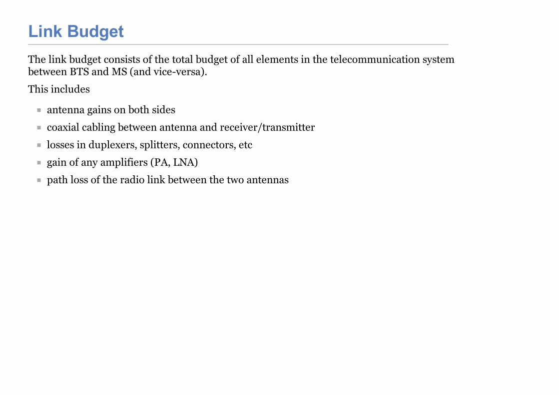
Link BudgetThe link budget consists of the total budget of all elements in the telecommunication systembetween BTS and MS (and vice-versa).
This includes
antenna gains on both sides
coaxial cabling between antenna and receiver/transmitter
losses in duplexers, splitters, connectors, etc
gain of any amplifiers (PA, LNA)
path loss of the radio link between the two antennas

Simplified Link Budget EquationThe simplified link budget equations looks like this:
Rx Power (dBm) = Tx Power (dBm) + Gains (dB) − Losses (dB)
Gains is the sum of all gains, including
Gain of the transmitter antenna
Gain of the receiver antenna
Gain of any PA (transmitter) or LNA (receiver)
Losses is the sum of all losses, including
Loss of any cabling and/or connectors on either side
Loss of any passive components like duplexers/splitters on either side
Path Loss of the radio link

Link Budget Equation vs. Path LossUsing the Link Budget equation and resolving it for the path loss will give you an idea ofhow much path loss on the radio link you can afford while still having a reliable radio link.
Resolving the path loss into a physical distance based on your path loss model will thengive you an idea about the coverage area that you can expect.
NOTE
The Rx Power substituted in the Link budget equation is determined by the receiversensitivity. It is customary to add some some safety margin to cover for fading.

RF Link
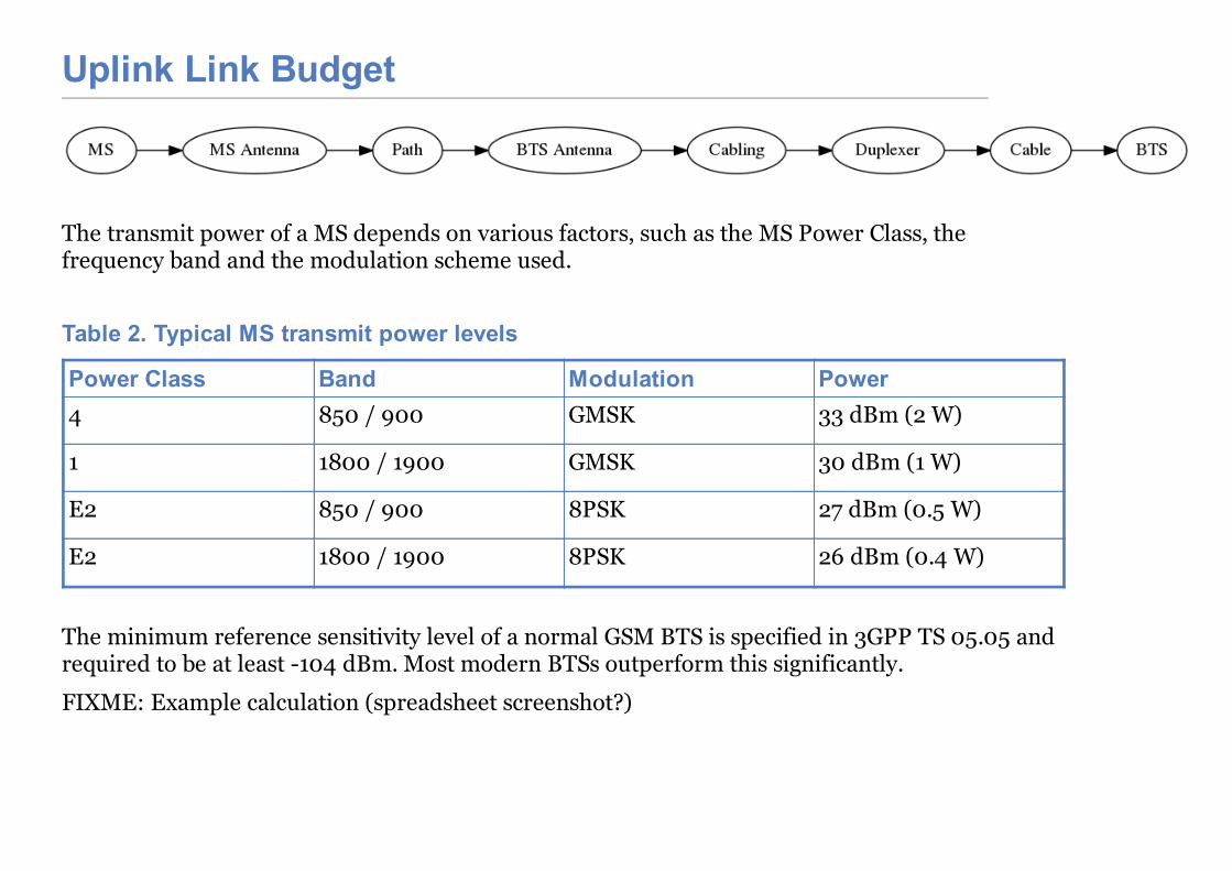
Uplink Link Budget
The transmit power of a MS depends on various factors, such as the MS Power Class, thefrequency band and the modulation scheme used.
Table 2. Typical MS transmit power levels
Power Class Band Modulation Power4 850 / 900 GMSK 33 dBm (2 W)
1 1800 / 1900 GMSK 30 dBm (1 W)
E2 850 / 900 8PSK 27 dBm (0.5 W)
E2 1800 / 1900 8PSK 26 dBm (0.4 W)
The minimum reference sensitivity level of a normal GSM BTS is specified in 3GPP TS 05.05 andrequired to be at least -104 dBm. Most modern BTSs outperform this significantly.
FIXME: Example calculation (spreadsheet screenshot?)
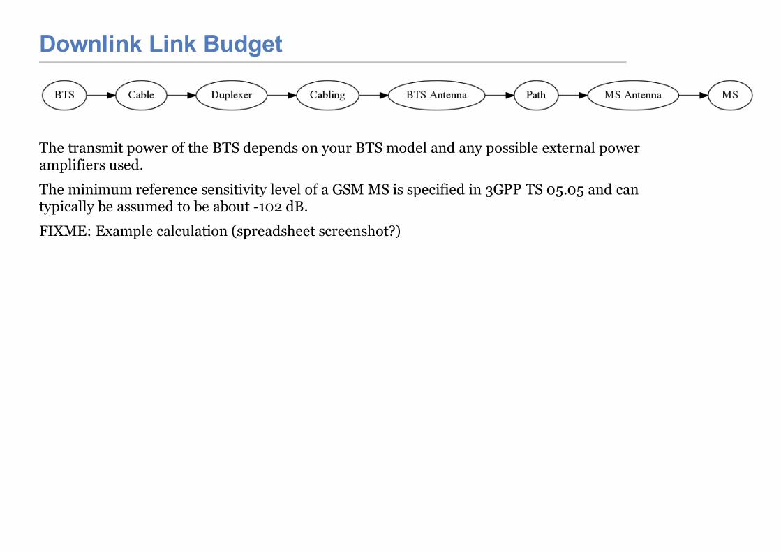
Downlink Link Budget
The transmit power of the BTS depends on your BTS model and any possible external poweramplifiers used.
The minimum reference sensitivity level of a GSM MS is specified in 3GPP TS 05.05 and cantypically be assumed to be about -102 dB.
FIXME: Example calculation (spreadsheet screenshot?)
Optimization of the Link BudgetIf the coverage area determined by the above procedure is insufficient, you can try to changesome of the parameters, such as
increasing transmit power by adding a bigger PA
increasing antenna gain by using a higher gain antenna
reducing cable losses by using better / shorter coaxial cables
increasing the height of your antenna

Coaxial Cabling
Introduction into RF ElectronicsSetup and Operation of a GSM network is not only about the configuration and systemadministration on the network elements and protocol stack, but also includes the physical radiotransmission part.
Basic understanding about RF (Radio Frequency) Electronics is key to achieving goodperformance of the GSM network.
Coaxial cables come in many different shapes, diameters, physical construction, dielectricmaterials, and last but not least brands and types.
There are many parameters that might be relevant to your particular installation, starting frommechanical/environmental properties such as temperature range, UV resilience,water/weatherproofness, flammability, etc.
For the subject of this manual, we will not look at those mechanical properties, but look at theelectrical properties instead.
The prime electrical parameters of a coaxial cable are:
its attenuation over frequency and length
its maximum current/power handling capability
its propagation velocity (ignored here)
its screening efficiency (ignored here)
Coaxial Cable AttenuationThe attenuation of a coaxial cable is given in dB per length, commonly in dB per 100m. This value
The attenuation of a coaxial cable is given in dB per length, commonly in dB per 100m. This valuechanges significantly depending on the frequency of the signal transmitted via the cable. Cablemanufacturers typically either provide tables with discrete frequency values, or graphs plottingthe attenuation per 100m (x axis) over the frequency (y axis).
FIXME: Example.
So in order to estimate the loss of a coaxial cable, you need to
1. determine the frequency at which you will use the cable, as determined by the GSMfrequency band of your BTS. Make sure you use the highest frequency that might occur,which is typically the upper end of the transmit band, see [gsm-bands]
2. determine the attenuation of your cable per 100m at the given frequency (check the cabledata sheet)
3. scale that value by the actual length of the cable
A real cable always has connectors attached to it, please add some additional losses for theconnectors that are attached. 0.05 dB per connector is a general rule of thumb for the frequenciesused in GSM.
FIXME: Example computation
As you can see very easily, the losses incurred in coaxial cables between your antenna and the BTScan very quickly become significant factors in your overall link budget (and thus cell coverage).This is particularly relevant for the uplink power budget. Every dB you loose in the antenna cablebetween antenna and the BTS receiver translates into reduced uplink coverage.
Using the shortest possible coaxial cabling (e.g. by mounting the BTS high up on the antennatower) and using the highest-quality cabling are the best strategies to optimize
WarningIf you plan to assemble the coaxial connectors yourself, please make sure

Coaxial Connectors
WarningIf you plan to assemble the coaxial connectors yourself, please make sureyou ensure to have the right skills for this. Properly assembling coaxialconnectors (whether solder-type or crimp-type) requires precision toolsand strict process as described by the manufacturer. Any mechanicalimprecision of connector assembly will cause significant extra signalattenuation.
Checking coaxial cablesIf you would like to check the proper operation of a coaxial cable, there are several possiblemethods available:
The more expensive method would be to use a RF Network Analyzer to measure theS11/S12 parameters or the VSWR of the cable.
Another option is to use a TDR (time domain reflectometer) to determine the VSWR. TheTDR method has the added advantage that you can localize any damage to the cable, assuch damage would cause reflections that can be converted into meters cable length fromthe port at which you are testing the cable. Mobile, battery-powered TDR for field-use inGSM Site installation are available from various vendors. One commonly used series is theAnritsu Site Master.
A coaxial connector is a connector specifically designed for mounting to coaxial cable. It facilitatesthe removable / detachable connection of a coaxial cable to a RF device.
There are many different types of coaxial connectors on the market.
The most important types of coaxial connectors in the context of GSM BTSs are:
The N type connector
Duplexers
The N type connector
The SMA type connector.
The 7/16 type connector
FIXME: Images
The above connectors are tightened by a screw-on shell. Each connector type has a specificdesignated nominal torque by which the connector shall be tightened. In case of uncertainty,please ask your connector supplier for the nominal torque.
Note Always ensure the proper mechanical condition of your RF connectors. Don’tuse RF connectors that are contaminated by dust or dirt, or which showsignificant oxidization, bent contacts or the like. Using such connectors posessignificant danger of unwanted signal loss, and can in some cases even lead toequipment damage (e.g. in case of RF power at PA output being reflected backinto the PA).
A GSM BTS (or GSM TRX inside a BTS) typically exposes separate ports for Rx (Receive) and Tx(Transmit). This is intentionally the case, as this allows the users to add e.g. additional poweramplifiers, filters or other external components into the signal path. Those components typicallyoperate on either the receive or the transmit path.
You could now connect two separate antennas to the two ports (one for Rx, one for Tx). This iscommonly done in indoor installations with small rubber-type antennas directly attached to theBTS connectors.In outdoor installations, you typically (want to) use a single Antenna for Rx and Tx. This single
RF Power Amplifiers
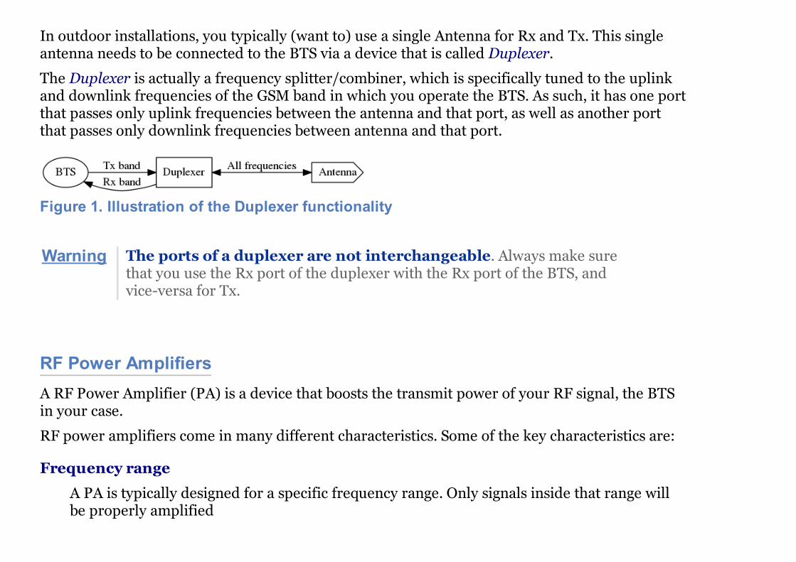
In outdoor installations, you typically (want to) use a single Antenna for Rx and Tx. This singleantenna needs to be connected to the BTS via a device that is called Duplexer.
The Duplexer is actually a frequency splitter/combiner, which is specifically tuned to the uplinkand downlink frequencies of the GSM band in which you operate the BTS. As such, it has one portthat passes only uplink frequencies between the antenna and that port, as well as another portthat passes only downlink frequencies between antenna and that port.
Figure 1. Illustration of the Duplexer functionality
Warning The ports of a duplexer are not interchangeable. Always make surethat you use the Rx port of the duplexer with the Rx port of the BTS, andvice-versa for Tx.
A RF Power Amplifier (PA) is a device that boosts the transmit power of your RF signal, the BTSin your case.
RF power amplifiers come in many different characteristics. Some of the key characteristics are:
Frequency range
A PA is typically designed for a specific frequency range. Only signals inside that range willbe properly amplified
Gain in dB
Gain in dB
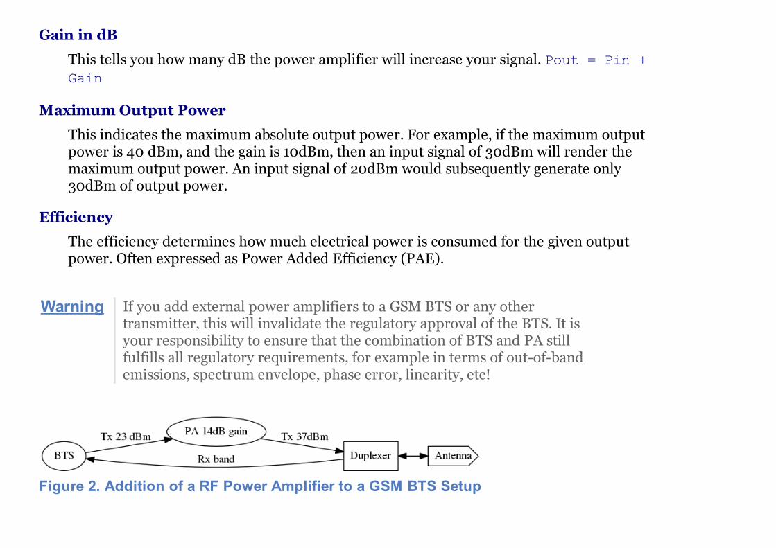
This tells you how many dB the power amplifier will increase your signal. Pout = Pin +Gain
Maximum Output Power
This indicates the maximum absolute output power. For example, if the maximum outputpower is 40 dBm, and the gain is 10dBm, then an input signal of 30dBm will render themaximum output power. An input signal of 20dBm would subsequently generate only30dBm of output power.
Efficiency
The efficiency determines how much electrical power is consumed for the given outputpower. Often expressed as Power Added Efficiency (PAE).
Warning If you add external power amplifiers to a GSM BTS or any othertransmitter, this will invalidate the regulatory approval of the BTS. It isyour responsibility to ensure that the combination of BTS and PA stillfulfills all regulatory requirements, for example in terms of out-of-bandemissions, spectrum envelope, phase error, linearity, etc!
Figure 2. Addition of a RF Power Amplifier to a GSM BTS Setup
AntennasThe Antenna is responsible for converting the electromagnetic waves between the coaxial cableand the so-called air interface and vice-versa. The properties of an antenna are always symmetricfor both transmission and reception.
Antennas come in many different types and shapes. Key characteristics distinguishing antennasare:
Antenna Gain
Expresses how much more efficient the antenna converts between cable and air interface.Can be expressed in dB compared to a theoretical isotropic radiator (dBi) or compared to adipole antenna (dBd). Gain usually implies directivity.
Frequency Band(s)
Antennas typically have only a relatively narrow band (or multiple narrow bands at whichthey radiate efficiently. In general, the higher the antenna gain, the lower the usablefrequency band of the antenna.
Directivity
Antennas radiate the energy in all three dimensions.
Mechanical Size
Mechanical Size is an important factor depending on how and where the antenna is mounted.Size also relates to weight and wind-load.
Wind Load
Expresses how much mechanical load the antenna will put on its support structure (antenna
Expresses how much mechanical load the antenna will put on its support structure (antennamast).
Connector Type
Your cabling will have to use a compatible connector for the antenna. Outdoor antennastypically use the 7/16 type connector or an N type connector. Indoor antennas either N typeor SMA type.
Environmental Rating
Indoor antennas cannot be used outdoor, as they do not offer the level of protection againstdust and particularly water / humidity / corrosion.
Down-tilt Capability
Particularly sector antennas are typically installed with a fixed or (mechanically / electrically)variable down-tilt in order to limit the radius/horizon of the antenna footprint and avoidexcess interference with surrounding cells.
VSWR
The Voltage Standing Wave Ratio indicates how well the antenna is matched to the coaxialcable, and how much of the to-be-transmitted radio signal is actually converted to radiowaves versus reflected back on the RF cable towards the transmitter. An ideal antenna has aVSWR of 1 (sometimes written 1:1). Real antennas are typically in the range of 1.2 to 2.
Side Lobes
A directional antenna never radiates only in one direction but always has certain side lobespointing outside of the main direction of the antenna. The number and strength of side lobesdiffer from antenna to antenna model.

Note Whenever installing antennas it is important to understand that any metallic orotherwise conductive object in their vicinity will inevitably alter the antennaperformance. This can affect the radiation pattern, but also de-tune theantenna and shift its frequency band outside the nominal usable frequencyband. It is thus best to mount antennas as far as practically possible fromconductive elements within their radiation pattern
Omni-directional AntennasOmni-directional antennas are typically thin long dipole antennas covered with fiberglass. Theyradiate with equal strength in all directions and thus result in a more or less circular cell footprint(assuming flat terrain). The shape of the radiation pattern is a torus (donut) with the antennalocated in the center of that torus.
Omni-directional antennas come with a variety of gains, typically from 0 dBd to 3 dBd, 6 dBd andsometimes 9 dBd. This gain is achieved by compressing the radiation torus in the vertical plane.
Sometimes, Omni-directional antennas can be obtained with a fixed down-tilt to limit the cellradius.
Sector AntennasSector antennas are used in sectorized cell setups. Sector antennas can have significantly highergain than omni-directional antennas.
Instead of mounting a single BTS with an omni-directional antenna to a given antenna pole,multiple BTSs with each one sector antenna are mounted to the same pole. This results in anoverall larger radius due to the higher gain of the sector antennas, and also in an overall capacityincrease, as each sector has the same capacity as a single omni-directional cell. And all that
benefit still requires only a single physical site with antenna pole, power supply, back-haul

RF Low Noise Amplifier (LNA)
benefit still requires only a single physical site with antenna pole, power supply, back-haulcabling, etc.
Experimentation and simulation has shown that typically the use of three sectors with antennas ofan opening angle of 65 degrees results in the most optimal combination for GSM networks. Ifmore sectors are being deployed, there is a lot of overlap between the sectors, and the amount ofhand-overs between the BTSs is increased.
A RF Low Noise Amplifier (LNA) is a device that amplifies the weak received signal. In general,LNAs are combined with band filters, to ensure that only those frequencies within the receiveband are amplified, and out-of-band interferers are filtered out. A duplexer can already be asufficient band-filter, depending on its characteristics.
The use of a LNA typically only makes sense if you . have very long and/or lossy coaxial cablesfrom your antenna to the BTS, and . can mount the duplexer + LNA close to the antenna, so thatthe amplification happens before the long/lossy coaxial line to the BTS
Key characteristics of a LNA are:
Frequency range
A LNA is typically designed for a specific frequency range. Only signals inside that range willbe properly amplified
Gain in dB
This tells you how many dB the low noise amplifier will increase your signal. Pout = Pin +Gain
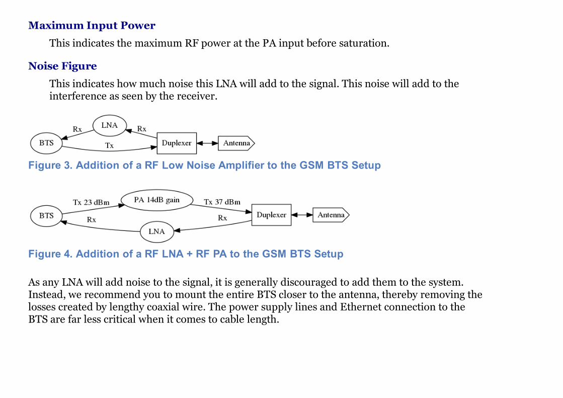
Maximum Input Power
Maximum Input Power
This indicates the maximum RF power at the PA input before saturation.
Noise Figure
This indicates how much noise this LNA will add to the signal. This noise will add to theinterference as seen by the receiver.
Figure 3. Addition of a RF Low Noise Amplifier to the GSM BTS Setup
Figure 4. Addition of a RF LNA + RF PA to the GSM BTS Setup
As any LNA will add noise to the signal, it is generally discouraged to add them to the system.Instead, we recommend you to mount the entire BTS closer to the antenna, thereby removing thelosses created by lengthy coaxial wire. The power supply lines and Ethernet connection to theBTS are far less critical when it comes to cable length.
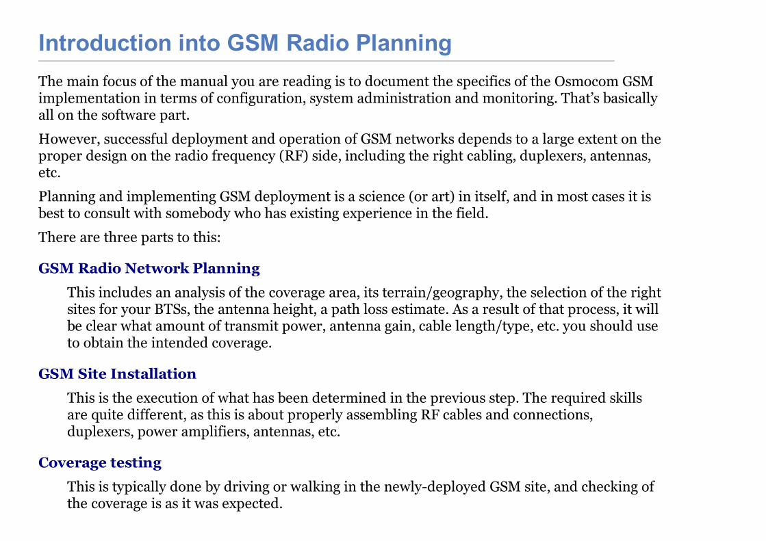
Introduction into GSM Radio PlanningThe main focus of the manual you are reading is to document the specifics of the Osmocom GSMimplementation in terms of configuration, system administration and monitoring. That’s basicallyall on the software part.
However, successful deployment and operation of GSM networks depends to a large extent on theproper design on the radio frequency (RF) side, including the right cabling, duplexers, antennas,etc.
Planning and implementing GSM deployment is a science (or art) in itself, and in most cases it isbest to consult with somebody who has existing experience in the field.
There are three parts to this:
GSM Radio Network Planning
This includes an analysis of the coverage area, its terrain/geography, the selection of the rightsites for your BTSs, the antenna height, a path loss estimate. As a result of that process, it willbe clear what amount of transmit power, antenna gain, cable length/type, etc. you should useto obtain the intended coverage.
GSM Site Installation
This is the execution of what has been determined in the previous step. The required skillsare quite different, as this is about properly assembling RF cables and connections,duplexers, power amplifiers, antennas, etc.
Coverage testing
This is typically done by driving or walking in the newly-deployed GSM site, and checking ofthe coverage is as it was expected.

GSM Radio Network Planning
Note This chapter can only give you the briefest overview about the process used,and cannot replace the experience and skill of somebody with GSM RFplanning and site deployment.
In GSM Radio Network Planning, the number and location of sites as well as type of requiredequipment is determined based on the coverage requirements.
For the coverage of a single BTS, this is a process that takes into consideration:
the terrain that needs to be covered
the type of mobile stations to be supported, and particularly the speed of their movement(residential, pedestrians, trains, highways)
the possible locations for cell sites, where BTSs and Antennas can be placed, as well as thepossible antenna mounting height
the equipment choices available, including
type and capabilities of BTS. The key criteria here is the downlink transmit powerin dBm, and the uplink receive sensitivity.
antenna models, including gain, radiation pattern, etc.
RF cabling, including the key aspect of attenuation per length
RF duplexers, splitting the transmit and receive path
power amplifiers (PAs), increasing the transmit power
low noise amplifiers (LNAs), amplifying the received signalFor coverage of an actual cellular network consisting of neighboring cells, this process also must
The Decibel (dB) and Decibel-Milliwatt (dBm)
For coverage of an actual cellular network consisting of neighboring cells, this process also musttake into consideration aspects of frequency planning, which is the allocation of frequencies(ARFCNs) to the individual cells within the network. As part of that, interference generated byfrequency re-use of other (distant) cells must be taken into consideration. The details of thiswould go beyond this very introductory text. There is plenty of literature on this subject available.
RF engineering heavily depends on the Decibel (dB) as a unit to express attenuation (losses) oramplification (gain) impacted on radio signals.
The dB is a logarithmic unit, it is used to express the ratio of two values of physical quantity. Youcan thus not express an absolute value in dB, only relative.
Note Relative loss (cable, connector, duplexer, splitter) or gain (amplifiers) arepower is expressed in dB.
In order to express an absolute value, you need to use a unit like dBm, which is referencing apower of 1 mW (milli-Watt).
Note Absolute power like transmitter output power or receiver input power isexpressed in dBm.
Table 3. Example table of dBm values and their corresponding RF Power
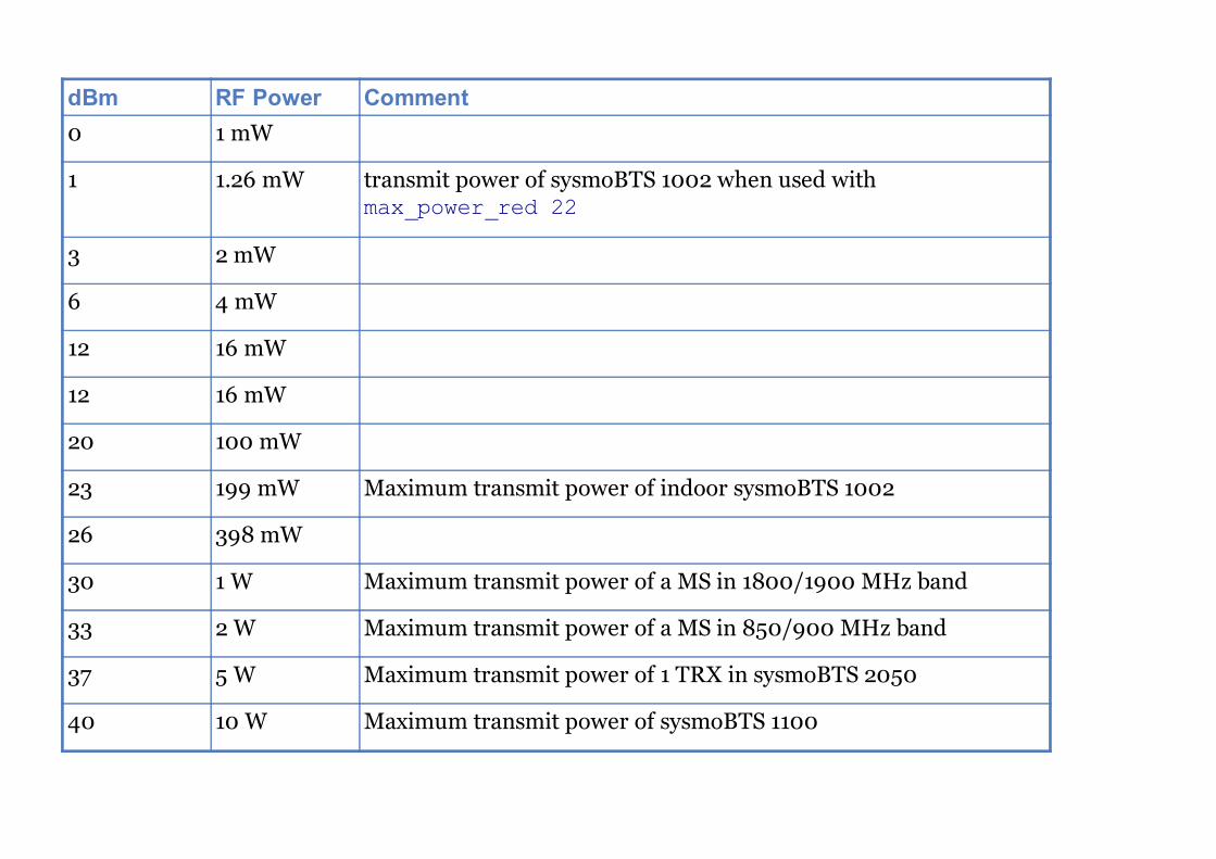
dBm RF Power Comment0 1 mW
1 1.26 mW transmit power of sysmoBTS 1002 when used withmax_power_red 22
3 2 mW
6 4 mW
12 16 mW
12 16 mW
20 100 mW
23 199 mW Maximum transmit power of indoor sysmoBTS 1002
26 398 mW
30 1 W Maximum transmit power of a MS in 1800/1900 MHz band
33 2 W Maximum transmit power of a MS in 850/900 MHz band
37 5 W Maximum transmit power of 1 TRX in sysmoBTS 2050
40 10 W Maximum transmit power of sysmoBTS 1100

GSM Frequency BandsGSM can operate in a variety of frequency bands. However, internationally only the following fourbands have been deployed in actual networks:
Table 4. Table of GSM Frequency Bands
Name Uplink Band Downlink Band ARFCN RangeGSM 850 824 MHz .. 849 MHz 869 MHz .. 894 MHz 128 .. 251
E-GSM 900 880 MHz .. 915 MHz 925 MHz .. 960 MHz 0 .. 124, 975 .. 1023
DCS 1800 1710 MHz .. 1785 MHz 1805 MHz .. 1880 MHz 512 .. 885
PCS 1900 1850 MHz .. 1910 MHz 1930 MHz .. 1990 MHz 512 .. 810

The EndQuestions?


![P R E O P E R A T O R I O[1]](https://static.fdocuments.net/doc/165x107/55917cdf1a28ab38138b459b/p-r-e-o-p-e-r-a-t-o-r-i-o1.jpg)