
Passive Solar Design - ZonBak
45
passive z n k power that changed the world solar design
Transcript of Passive Solar Design - ZonBak

p a s s i v e
z n kpower that changed the world
s o l a r
d e s i g n

SOLAR ENERGY BASICS
The ancient Native American cliff dwellers understood more about passive solar design than most modern architects and builders. Before the days of oil-burning furnaces, cheap electricity, and triple-glazed windows, Native Americans had to rely on passive solar energy for both heating and cooling of their dwellings. In the Southwest, they built into cliffs. Most of these cliff dwellings were erected on south-facing ledges in deep sandstone canyons. Thanks to their southern exposure, the low-riding sun provided heat during the winter and the overhanging cliff above offered cool shade from the high summer sun.
American Indian culture that roamed the Southwest from 1200 B.C. to A.D. 1300 built cliff dwellings such as these at Manitou Springs Colorado. With a southwest exposure and overhanging cliffs they are excellent examples of passive solar design.
This guide describes to builders, architects and homeowners techniques they can employ to dramatically reduce the energy “footprint” of structures that they build. The techniques do not rely on advanced and expensive technologies such as photovoltaicpanels, triple glazed solar windows, or a foot or more of insulation. Many of the gains, are achieved by applying simple design practices and by employing materials like
concrete and water. There is an infinite number of combinations of these simple solutions, with the best often determined by the site location, the local year-round climate, and the construction budget. But before we discuss specific design practices it is beneficial to understand solar energy.
solar energy The sun’s energy arrives on earth in the form of heat and light. This solar radiation travels through space in waves, and it is the wavelength of these light waves that what we call the solar spectrum. There are two important facets you need to consider about the solar spectrum. First, while the sun emits radiation in all wavelengths (from less than a millionth of an inch to more than a thousand
yards), it is the shorter wavelengths that account for the majority of energy in the solar spectrum. For example, the portion of the spectrum we see as visible light is a relatively small segment, yet accounts for 46 percent of the energy radiating from the sun. Another 49 percent, that whichwe perceive as heat, is derived from the relatively
narrow infrared band of the spectrum. Because the proportion of different wavelengths in the solar spectrum is fixed, the energy output of the sun remains constant. This phenomena is known as the Solar Constant. We define this as the amount of heat energy delivered in one hour to a square foot perpendicular to the sun’s rays at the outer edge of the earth’s atmosphere. The Solar Constant measurement is roughly 430 BTUs/ft2
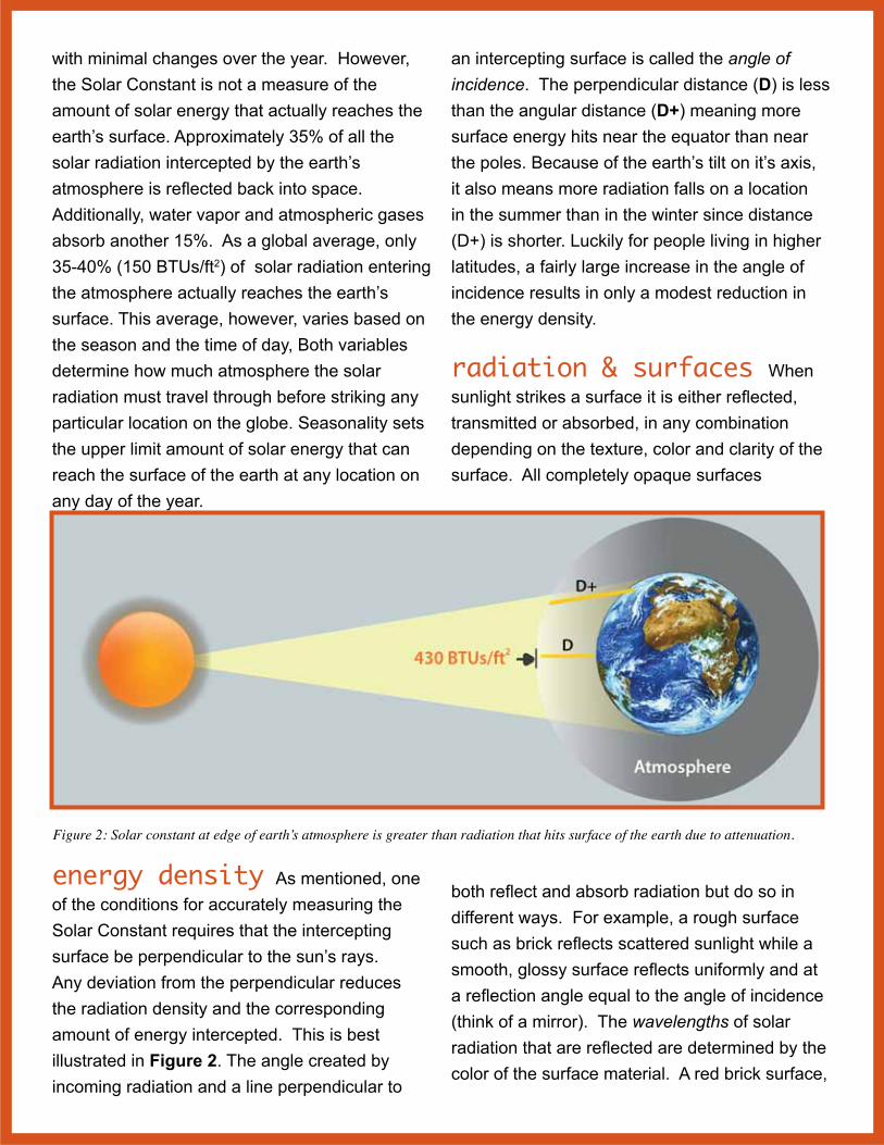
with minimal changes over the year. However, the Solar Constant is not a measure of the amount of solar energy that actually reaches the earth’s surface. Approximately 35% of all the solar radiation intercepted by the earth’s atmosphere is reflected back into space. Additionally, water vapor and atmospheric gases absorb another 15%. As a global average, only 35-40% (150 BTUs/ft2) of solar radiation entering the atmosphere actually reaches the earth’s surface. This average, however, varies based on the season and the time of day, Both variables determine how much atmosphere the solar radiation must travel through before striking any particular location on the globe. Seasonality sets the upper limit amount of solar energy that can reach the surface of the earth at any location on any day of the year.
Figure 2: Solar constant at edge of earth’s atmosphere is greater than radiation that hits surface of the earth due to attenuation.
energy density As mentioned, one of the conditions for accurately measuring the Solar Constant requires that the intercepting surface be perpendicular to the sun’s rays. Any deviation from the perpendicular reduces the radiation density and the corresponding amount of energy intercepted. This is best illustrated in Figure 2. The angle created by incoming radiation and a line perpendicular to
an intercepting surface is called the angle of incidence. The perpendicular distance (D) is less than the angular distance (D+) meaning more surface energy hits near the equator than near the poles. Because of the earth’s tilt on it’s axis, it also means more radiation falls on a location in the summer than in the winter since distance (D+) is shorter. Luckily for people living in higher latitudes, a fairly large increase in the angle of incidence results in only a modest reduction in the energy density.
radiation & surfaces When sunlight strikes a surface it is either reflected, transmitted or absorbed, in any combination depending on the texture, color and clarity of the surface. All completely opaque surfaces
both reflect and absorb radiation but do so in different ways. For example, a rough surface such as brick reflects scattered sunlight while a smooth, glossy surface reflects uniformly and at a reflection angle equal to the angle of incidence (think of a mirror). The wavelengths of solar radiation that are reflected are determined by the color of the surface material. A red brick surface,

for example, will scatter (diffuse) wavelengths in the red band of the spectrum and absorb all others, while a white glossy surface will reflect all wavelengths in the visible spectrum at an angle equal and opposite to the angle of incidence. Conversely, a rough black surface absorbs all wavelengths in the visible spectrum. The transparent surface of window glass allows nearly all radiation to pass through it with comparatively little reflection or adsorption, and without deflecting it from its parallel lines of travel. Translucent materials also transmit radiation but scatter the rays as they pass. It should be noted that few materials are either excellent reflectors, transmitters, or absorbers of the sun’s rays.
Figure 3: Absorption (yellow) and emissitivity (red) of common building materials and solar thermal panels. A high absorption and low emissitivity means the material captures and keeps most of the incident solar radiation.
solar absorption Sunlight exhibits a transformation from solar energy to heat energy when it falls on any material. As a material absorbs solar energy it stimulates movement of the molecules in the material generating heat. The greater the movement, the greater the heat. We call this process absorption. In physics, absorption refers to the full spectrum. With passive solar, it refers to absorption over a specific spectral range of sunlight here on earth. Since the color black absorbs more of the light spectrum than the color white (thus more energy), black surfaces will be hotter than
white surfaces. A flat black paint can have an absorption factor as high as 98%. This means that 98% of the incident solar energy is converted into heat. The radiation that is not absorbed, is lost due to reflection. Mirrors or polished metals are poor absorbers (absorption of 5 to 10%), since most of the light is reflected rather than absorbed. Table 1 shows absorption factors of some common, solar absorbers and finishes such as paint.
heat conduction As a material absorbs radiation, it will redistribute heat energy due to the natural phenomenon of maintaining equilibrium. This occurs when stimulated
molecules vibrating at a faster rate impact adjacent molecules vibrating at a slower rate. In this way, heat is conducted away from the source of energy and the energy distributes evenly throughout the mass. The rate at which energy “flows” or is conducted though a material depends on the density of the material and its conduction rate. Gases are poor conductors; metals are comparatively good conductors; and less dense materials containing tiny air pockets and voids (insulators) conduct heat at the least rate. In passive solar designs, you want the “C student” when it comes to conductivity. You need the heat storage material to absorb the heat over

the course of the day, and then slowly release it over several hours at night. Concrete, bricks, and wood all satisfy this requirement.
heat transfer Heat transfer from a solid material to a fluid medium (liquid or gas) occurs by radiation (infrared). Fluids can also move across a hot solid surface, allowing molecules of the fluid to become agitated (heated), then move away from the heat source, and be replaced by new, unheated molecules. When no machinery aids the process it is called natural convection. With an aid such as a fan it is called forced convection. Boiling water is a good example natural convection with heated molecules near the burner rising quickly to the surface where they boill off. Steam generated by boiling is simply water molecules whose vibration rate is violent enough to allow them to breakaway from of the water’s surface. Heat rising off pavement is also evidence of the power of natural convection. Air heated by dark pavement rises, creating a shimmering or “mirage” effect when viewed from afar.
Table 1: Solar Characteristics of MaterialsMaterial Absorption Emissivity RatioAnodized Aluminum 0.14 0.84 .17White Paint (typ.) 0.39 0.82 .48Colored Paints 0.50-0.70 0.85-0.95 .67Concrete 0.60 0.88 .68Galvanized Metal 0.65 0.13 5.00Brick, red 0.65 0.93 .68Concrete & Stone 0.65-0.80 0.85-0.95 .81Flat Black Paint 0.97 0.97 1.00Black Anodized Alu-minum
.88 .88 1.00
Selective Solar* 0.98 0.14 8.00* Materials used in solar collectors such as ZonBak solar ther-mal panels.
emissivity Molecular movement is continually generating heat in the form of radiant energy. Unlike solar energy, radiant energy is limited to low-temperature infrared radiation. The emission of thermal energy depends both on the temperature of the material and its surface. Polished metal surfaces have low thermal emission but also poor absorption of solar radiation. In contrast, black metal surfaces are the best absorbers but sometimes have high emission. Flat black paint, for example, while cheap to apply, it not necessarily the best material to use for a solar collector. It absorbs well, but also emits just as well.
In selecting passive solar materials you need to consider both absorption and emissivity. The higher the absorption the more you collect; the lower the emissivity, the less you lose. Ideally the emissivity should be zero. Of course that would be impossible. The best alternative is to look for materials that have high absorption and low emissivity. Brick, for example, will absorb 65% of incident radiation and release 88% of that right back at the surface (Figure 3). That leaves only 12% to be stored for later use. The “ideal” surfaces for absorbing and not emitting solar radiation are specialized coated metals (copper and aluminum) used in Zonbak solar thermal panels. The absorption is close to 100% and the emissivity is as low as 10%, meaning the material will convert almost all the solar radiation to heat and lose only 10% of it back from its surface. However, since they have a such small thermal mass, they will not store the heat. It must be transferred to a heat storage material (concrete, water, etc.) via passive or active convection.
Glass has the special characteristic of transmitting nearly all solar radiation. Solar
energy passes through windows and is reradiated into an interior space in the form of thermal energy (heat). The heat is unable to pass back through the glass to the outside since glass blocks infrared thermal radiation. This is known as the greenhouse effect.
heat storage All materials can store heat which is called its specific heat; the amount of heat, measured in BTU’s for a given mass, a material can hold when its temperature is raised by one degree Fahrenheit. However, the specific heat of a material is not very useful when evaluating materials for passive solar designs. The more useful measure of a solar material is its heat capacity; a measurement of the specific heat of a material multiplied by its density. The higher the heat capacity, the more effective the material is for solar thermal storage. A good thermal storage material must absorb heat when it is available (daytime), and give it up when it is needed (nighttime). The rate at which a material absorbs heat is known as its conductivity.
Table 2: Specific heat capacity of building materialsMaterial J/(g-k) Asphalt 0.920Brick 0.840Concrete 0.880Glass 0.840Granite 0.790Gypsum 1.090Marble 0.880Sand 0.836Wood 1.7Water at 25°C 4.18
Table 2 shows the comparative specific heat measurements for a variety of common building materials. Unfortunately, there is no perfect storage medium in terms of volume, storage capacity, conductivity, and cost. Oak, for
example is fairly good at storing heat, but it is too expensive to use alone as a heat storage material. Water has one of the highest heat capacities and is basically free, but it is much more difficult from a maintenance standpoint. You need containers to store it, it freezes, and under pressure the water storage system tends to leak and cause damage. Plus “stagnant” water will start to grow bacteria if left unattended.
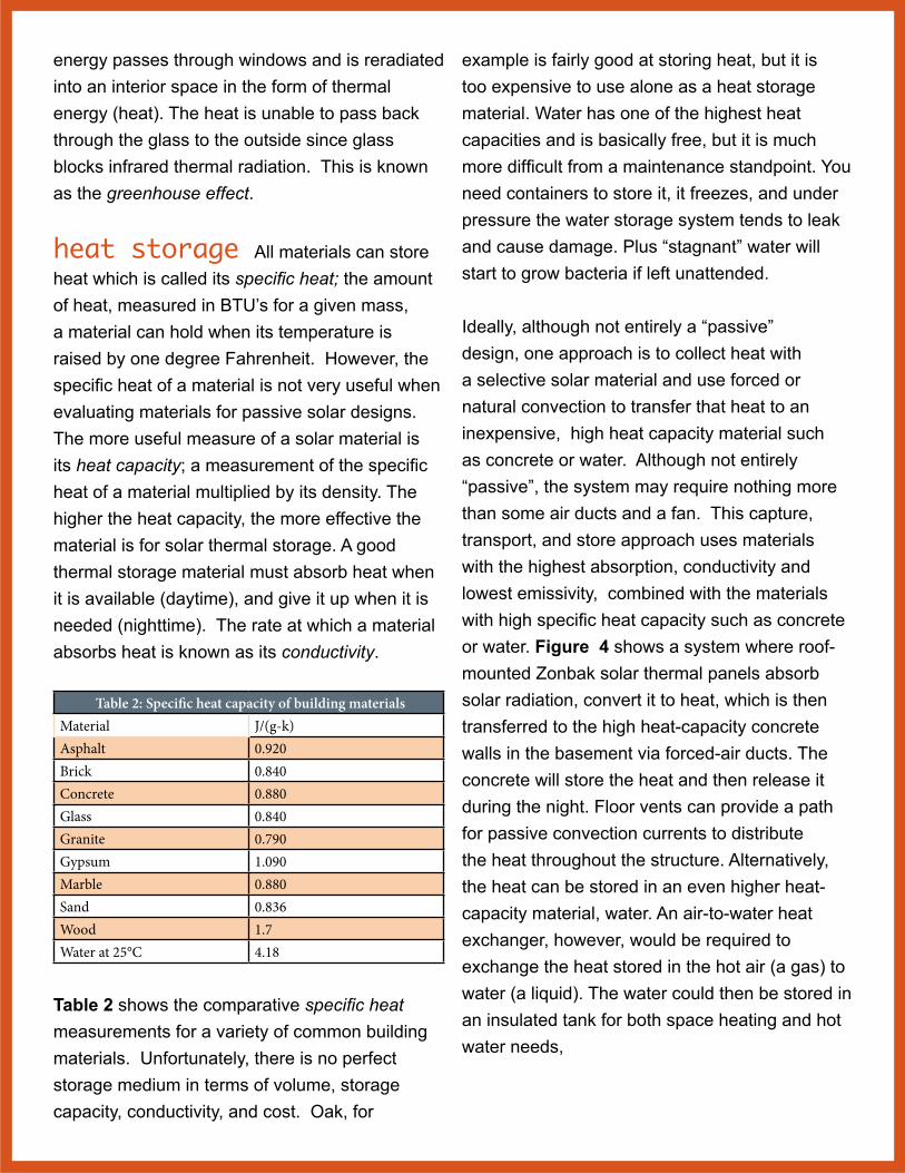
Ideally, although not entirely a “passive” design, one approach is to collect heat with a selective solar material and use forced or natural convection to transfer that heat to an inexpensive, high heat capacity material such as concrete or water. Although not entirely “passive”, the system may require nothing more than some air ducts and a fan. This capture, transport, and store approach uses materials with the highest absorption, conductivity and lowest emissivity, combined with the materials with high specific heat capacity such as concrete or water. Figure 4 shows a system where roof-mounted Zonbak solar thermal panels absorb solar radiation, convert it to heat, which is then transferred to the high heat-capacity concrete walls in the basement via forced-air ducts. The concrete will store the heat and then release it during the night. Floor vents can provide a path for passive convection currents to distribute the heat throughout the structure. Alternatively, the heat can be stored in an even higher heat-capacity material, water. An air-to-water heat exchanger, however, would be required to exchange the heat stored in the hot air (a gas) to water (a liquid). The water could then be stored in an insulated tank for both space heating and hot water needs,
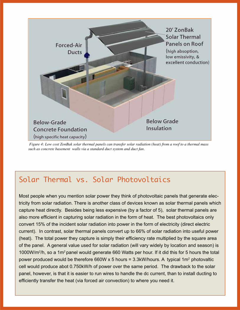
Figure 4: Low cost ZonBak solar thermal panels can transfer solar radiation (heat) from a roof to a thermal mass such as concrete basement walls via a standard duct system and duct fan.
Solar Thermal vs. Solar Photovoltaics
Most people when you mention solar power they think of photovoltaic panels that generate elec-tricity from solar radiation. There is another class of devices known as solar thermal panels which capture heat directly. Besides being less expensive (by a factor of 5), solar thermal panels are also more efficient in capturing solar radiation in the form of heat. The best photovoltaics only convert 15% of the incident solar radiation into power in the form of electricity (direct electric current). In contrast, solar thermal panels convert up to 66% of solar radiation into useful power (heat). The total power they capture is simply their efficiency rate multiplied by the square area of the panel. A general value used for solar radiation (will vary widely by location and season) is 1000W/m2/h, so a 1m2 panel would generate 660 Watts per hour. If it did this for 5 hours the total power produced would be therefore 660W x 5 hours = 3.3kW/hours. A typical 1m2 photovaltic cell would produce abot 0.750kW/h of power over the same period. The drawback to the solar panel, however, is that it is easier to run wires to handle the dc current, than to install ducting to efficiently transfer the heat (via forced air convection) to where you need it.

PASSIVE SOLAR HEATING
Passive solar heating is the most cost effective method to heat buildings. In most locations, the amount of solar energy that falls on the roof of a house is more than the total energy consumed within the house. In passive solar architecture, much of this wasted heat can be captured without adding substantially to the cost of the structure. A passive solar and energy efficient design can reduce the monthly operational costs and dramatically increase the resale value of any home. Because heating and cooling require the most energy in most homes, they will be the greatest part of any household’s utility bill. Consequently, reducing heating and cooling requirements via a passive design can generate large monthly savings, typically from 50 to 70%.
Figure 5: Chart showing typical household energy consumption by system. Heating and cooling are the largest energy users and can therefore generate the greatest savings with a passive design.
Most buildings are designed with a heating/cooling system using forced air or water (furnace, boiler, radiant floor, etc.) In passive building designs, the heating/cooling system is integrated
into the building design elements and materials: the windows, walls, floors, and roof are all used as the heat collecting, storing, releasing, and distributing system. Understand that passive solar does not necessarily mean the elimination of standard mechanical systems, although high efficiency back-up heating systems greatly reduce the size of the traditional heating systems and reduce the amount of non-renewable fuels needed to maintain comfortable indoor temperatures, even in the coldest climates.
Two elements must be present in all passive solar heating designs: a south facing exposure of transparent material (glass, plastic) to allow solar energy to enter; and a material to absorb and store the heat. With these two basic elements, there are a number of approaches to designing a passive solar structure. Passive solar design generally falls into three general categories. They are defined in how the “solar gain” is achieved. They are:
• DirectGain• IndirectGain• IsolatedGain
The choice of one approach versus the other will be determined by a number of factors, including site location, climate, budget, etc. No one approach is incrementally more effective such that it will serve in all climates. Conversely, limitations inherent in one approach do not mean that it is ineffective, only that it is more effective under specific conditions. In choosing a particular design approach you need to evaluate site and climate conditions carefully to determine the best approach or combination of approaches. This guide is designed to give you some “rules of thumb” so you start the evaluation process.
Besides what is included in this guide is a vast wealth of information and tools that can help in the design process. For example, the national weather service has an online database and tools that let you accurately predict solar incidence (i.e. amount of sunlight) in a particular region or state. There are free design tools such as Google Sketchup™ that let you visualize how shading performs with a particular design in a specific location (the actual street address or geolocation). The simple guidelines described here will, if observed, produce favorable passive solar performance. But the actual results will be determined by the actual specific details of your design and approach.
direct gain The simplest passive home is a direct gain design. South facing glass admits sunlight to the interior space and virtually all of it can be converted into thermal energy. The walls and floor provide solar collection and thermal storage by absorbing direct, reflected, or reradiated energy. As long as the room temperature remains at normal, the storage mass will conduct heat. At night, when outside temperatures drops and the interior space cools, the heat flow reverses and heat is given up to the interior space until the thermal mass and room reach a temperature equilibrium. This re-radiation of collected daytime heat maintains a comfortable temperature during cool/cold nights and has the potential to extend through several cloudy days without “solar recharging”. When planning the southern facing wall, the amount of window area versus thermal mass and floor space should follow these general guidelines for best performance and minimal daily temperature fluctuations:
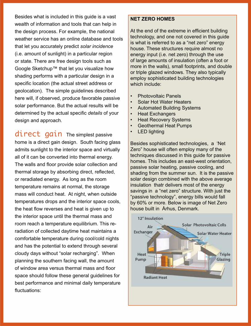
NET ZERO HOMES At the end of the extreme in efficient building technology, and one not covered in this guide is what is referred to as a “net zero” energy house. These structures require almost no energy input (i.e. net zero) through the use of large amounts of insulation (often a foot or more in the walls), small footprints, and double or triple glazed windows. They also typically employ sophisticated building technologies which include:
• Photovoltaic Panels• Solar Hot Water Heaters• Automated Building Systems• Heat Exchangers• Heat Recovery Systems• Geothermal Heat Pumps• LED lighting
Besides sophisticated technologies, a ‘Net Zero” house will often employ many of the techniques discussed in this guide for passive homes. This includes an east-west orientation, passive solar heating, passive cooling, and shading from the summer sun. It is the passive solar design combined with the above average insulation thatr delivers most of the energy savings in a “net zero” structure. With just the “passive technology”, energy bills would fall by 60% or more. Below is image of Net Zero house built in Århus, Denmark.

• In direct gain houses with no internal mass, the maximum allowable area of south-facing glass should be no more than 7 percent of the floor area.
• Direct gain systems can handle up to 12 percent of the floor area in south-facing windows.
• Every 1 square foot of south-facing glass over the 7 percent should be accompanied by 5 square feet of 4-inch-thick masonry.
Direct gain design can employ a wide variety of materials and combinations of ideas. Specifics will depend greatly upon the site and topography; building location and orientation; building shape (depth, length, and volume); and space use. A direct gain design requires that one-half to two-thirds of the total interior surface be thermal storage materials. Appropriate materials can include floor, ceiling and wall elements, and can range from masonry (concrete, adobe, brick, etc.) to water. The more advanced design would include a “water wall” due to its unparalleled ability to absorb and reradiate heat. Water stored within a plastic or a metal containment has the advantage of heating more quickly and evenly than masonry walls. Since water can “ flow” it creates a convection process that prevents surface temperatures from becoming too extreme as they sometimes do when dark colored masonry surfaces receive direct sunlight. However, the masonry heating problem can be alleviated by using a glazing material that scatters sunlight so that it is more evenly distributed over walls, ceiling, and floor storage. This decreases the intensity of rays reaching any single surface but does not reduce the amount of solar energy entering the space.
AdvantagesofaDirectGainSystem:• Low in cost to build, since no special room
has to be added.• Provides direct heating to the living space.• South-facing windows provide natural
daylight and outdoor views.
DisadvantagesofaDirectGainSystem:• It can overheat if you do not properly
balance windows and thermal mass.• Large areas of south-facing glass cause
problems with glare and loss of privacy.• You can not cover thermal mass by carpet
or block it by furnishings.• South-facing windows should have
summer shading and night time insulation in winter. In direct gain systems in colder climates heat will be lost quickly through even the best double or triple glazed windows.
Figure 6: Sloped glazing and no shading makes for a poor direct gain but good isolated gain system. The large amounts of heat produced in the summer will require isolation. The sloped windows will also be subject to leaking

indirect gain An indirect gain system uses the basic elements of heat collection and storage in combination with convection. In this approach, you place a dark-colored thermal storage wall (otherwise know as a “Trombe” wall) behind a south facing windows and in front of the living space. Sunlight enters through the glass and the surface immediately absorbs it. The stored heat is eventually conducted through the material mass to the inside space. In most cases, the masonry thermal storage mass can not absorb solar energy as fast as it enters the allocated space (concrete is a poor conductor). Consequently, temperatures on the wall can exceed 100°F even in the middle of the winter.
Besides direct conduction through a thermal wall, solar heat can be moved to adjacent space by providing a natural convection loop. Heated air flows out through heat-distributing vents at the top of the wall while vents at the bottom of the wall draw in cool air into the heating space. The top and bottom vents continue to circulate air as long as the air entering the bottom vent is cooler than the air leaving the top vent. Consequently, The storage mass continues to heat the interior space by radiation for six to eight hours. This time lag, as the mass warms and then gives off heat, keeps temperatures in the living space fairly uniform. It also means that the heating of the living area occurs in the evening and at night, when it is most needed.
One problem with an indirect gain is that it will restrict a view and light. Light can be addressed by adding a clerestory above the wall. There is not much you can do about the lost view, however. Consequently, a good location for indirect gain in many homes is the southern wall
of a garage it has a southern exposure. The view from a garage is largely wasted, so covering up the southern wall with an indirect gain or greenhouse space is ideal.
Figure 7 shows a south side entryway combined with a thermal wall and passive convection system. Duct work behind wall circulates air to and from the entryway into the house. The ducts on the bottom draw cooler air in, while the ducts on the top draws the warm air out. The wall can be built from concrete forms and then painted a dark color or covered with dark tiles. Because the entryway will be quite warm on sunny days, it is also a good location for plants. If proper shading and ventilation is provided, the thermal wall can provide cooling as well in the summer months. (See section on passive cooling.)
A variation of the vented masonry wall design is one that employs a water wall between the sun space and the interior space. Water walls used in this way need not be vented at top and bottom and can be constructed in many ways. You could even use 55-gallon drums filled with water, or specially constructed plastic or sealed concrete containers (see Figure 18). As the sun heats the water, the convection process quickly distributes the heat throughout the mass and the interior space is warmed by heat radiated from the wall.
Other than building a wall out of water barrels, there are some other alternatives. You can construct a south facing “greenhouse space” with water storage in the greenhouse. The water absorbs heat at the same time the sun heats the interior space of the greenhouse. The more water you have, then the more heat you can store. In addition, if you use a vented design, heat can also be released into the living space by

convection. The advantage is that a greenhouse condition can be maintained through days of no sun. As a backup for extended cloudy periods, however, you should provide secondary heating.
Figure 7. An indirect gain wall can be placed directly against a room you are trying to heat or nearby if you can employ convection air currents. This design shown turns what is normally a unheated entryway into an indirect gain system.
A more esthetic design could be to use what is typically referred to as an actual “water wall” In this type of wall shown in Figure 8, water circulates from a pool to the top of a rock wall, creating a waterfall effect. As water cascades
down the wall it heats up. In the “decorative only” design, the water pool at the bottom is only a few dozen gallons. But if you increase this to a few
hundred gallons, it will store large amounts of heat which will be released into the space over a long time period. If you add a duct system, then the air can flow from the greenhouse into the

house via convection currents. The design also acts as a natural humidifier since it will contain moisture as the water evaporates. The energy efficiency can be increased if you use a solar power panel to operate the water pump.
Figure 8. A water wall fountain can be used in an independent gain system. Instead of a small volume of water circulated, you can increase it to several hundred gallons.
AdvantagesofanIndirectGainSystem:
• The storage mass is located closer to the glass or collection area, which allows for efficient collection and storage of solar energy.
• The thermal mass prevents extreme temperature swings.
• The floor and wall area of the living space can be used with more flexibility than in a direct gain system.
• A Trombe wall system provides greater privacy on the south face of the house.
DisadvantagesofanIndirectGainSystem:
• The south-facing view and natural daylight are lost.
• Furniture and objects placed against or on the Trombe wall affect its efficiency in heating the living space.
• The Trombe wall heats only the room to which it is connected, so construction costs maybe
high relative to the contribution it makes to the overall heating needs of the house.
• The Trombe wall is a very poorly insulated wall and should be covered with exterior moveable insulation on summer days and winter days without sunshine.
isolated gain The isolated gain design approach uses a fluid (liquid or air) to collect heat in a solar collector such as a ZonBak solar thermal panel. Although not explicitly a “passive solar design”, it is simple enough to classify as such. With a hot-air solar panel, heat is distributed immediately through air ducts to interior rooms. Alternatively, the forced air can be directed into a rock (or other thermal mass such as a concrete slab) where heat is adsorbed. At night the interior space of the structure is heated by convection of the collected radiant energy from the thermal mass. Figure 4 shows an isolated thermal system where hot air is collected from rooftop solar thermal panels and distributed to a basement via a forced convection duct system. From the basement, the heat will automatically rise through the house via natural convection.
With new construction, isolated gain heat storage can be incorporated directly into the concrete slab construction; rock bins are rather obsolete. Today, it is almost a requirement to provide under-the-slab insulation to meet building codes. The most common slab insulation technique is to use rigid “pink” or “blue” foam boards. Sold under the trademark of Foamular® 400, 600, or 1000 the insulation offers good compressive strength (40, 60, and 100 psi, respectively.) so you can normally pour concrete directly onto it. On top of this insulation, however, you can also install galvanized decking then pour the concrete slab on top of that. The decking will provide rigid air-
flow channels beneath the slab to accommodate heated air. (Steel decking is commonly used in steel-girder buildings for concrete floors on each story).
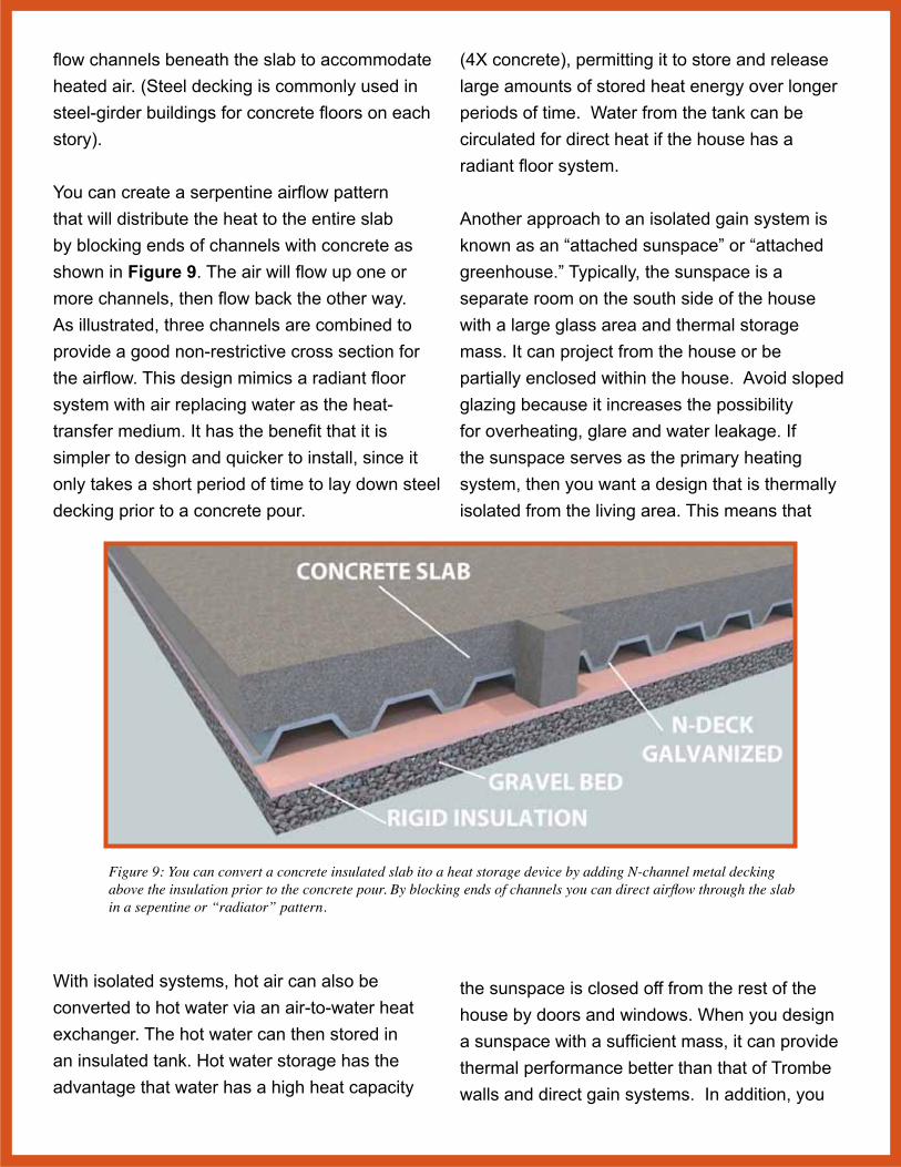
You can create a serpentine airflow pattern that will distribute the heat to the entire slab by blocking ends of channels with concrete as shown in Figure 9. The air will flow up one or more channels, then flow back the other way. As illustrated, three channels are combined to provide a good non-restrictive cross section for the airflow. This design mimics a radiant floor system with air replacing water as the heat- transfer medium. It has the benefit that it is simpler to design and quicker to install, since it only takes a short period of time to lay down steel decking prior to a concrete pour.
Figure 9: You can convert a concrete insulated slab ito a heat storage device by adding N-channel metal decking above the insulation prior to the concrete pour. By blocking ends of channels you can direct airflow through the slab in a sepentine or “radiator” pattern.
With isolated systems, hot air can also be converted to hot water via an air-to-water heat exchanger. The hot water can then stored in an insulated tank. Hot water storage has the advantage that water has a high heat capacity
(4X concrete), permitting it to store and release large amounts of stored heat energy over longer periods of time. Water from the tank can be circulated for direct heat if the house has a radiant floor system.
Another approach to an isolated gain system is known as an “attached sunspace” or “attached greenhouse.” Typically, the sunspace is a separate room on the south side of the house with a large glass area and thermal storage mass. It can project from the house or be partially enclosed within the house. Avoid sloped glazing because it increases the possibility for overheating, glare and water leakage. If the sunspace serves as the primary heating system, then you want a design that is thermally isolated from the living area. This means that
the sunspace is closed off from the rest of the house by doors and windows. When you design a sunspace with a sufficient mass, it can provide thermal performance better than that of Trombe walls and direct gain systems. In addition, you

can use awnings to block the sun to reduce build up of heat in the sunspace in the summer. Figure 10 shows an isolated sunspace that can be added to any south wall of a building. The space stores heat in a masonry wall in the form of 10” concrete blocks. With a forced convection system, you can use the empty center of the blocks as “concrete ducts” to circulate air through the entire mass. If you make the glazing removable for the summer months, the mass can also provide cooling since it will store cooler night time air. Some form of shading or exterior insulation should be provided to extend the daily cooling period, however.
AdvantagesofanIsolatedGainSystem:• It can be physically separated from the living
space, so that temperature fluctuations within the sunspace do not adversely affect the comfort of the living area.
• Sun spaces increase the resale value of a home.
• Solar thermal designs such as Zonbak panels can be retrofitted to existing structures.
• Solar thermal panels can be easily incorporated into any architectural style.
• Heat storage can be located in a basement or underground
DisadvantagesofanIsolatedGainSystem:• Heavy furnishings and rugs must be avoided
to prevent shading of the thermal storage mass.
• Shading and venting are important to avoid summertime overheating.
• They may require a forced convection system for best performance.
passive solar guidelines With passive solar design your goal is to capture the maximum solar radiation of the sun in the
winter. In the northern hemisphere, the sun will be due south, and the further north you go, the lower the sun will be on the horizon. Consequently, your home should face within 15°, plus or minus, of due south to receive maximum winter-heat gain. If the structure is 30° off axis by east or west of south solar, then it will reduce output by 15% due to the higher angle of incidence of the solar radiation. However, facing due south is not enough to ensure maximum solar gain; you must also make sure that the area to the south is clear of any obstructions blocking the sun in the winter between 9 a.m. and 3 p.m. At South Carolina’s latitudes, for example, this means that the area extending 45° south from the outer southern corners of the solar surfaces should be kept clear of any object that would shade them.
Figure 10: Isolated trombe wall combines masonry storage with air ducts for convection heating via standard air ducts.
You also need to match the passive solar heating system to your lifestyle. If you build a house you dislike just to achieve passive solar, then the exercise is useless. Furthermore, different passive designs require varying degrees of interaction — from seasonal shading that needs
to be added or removed twice a year, to movable insulation that needs to be adjusted frequently. In addition, unlike a traditional house design, you need to plan for then distribute the thermal mass through the room. In direct gain systems, performance is fairly insensitive to the locations of the mass in the room. It is relatively the same whether the mass is located on the floor or on the east, west or north walls. However, it is important to put some mass in direct sun, but rarely possible because of furniture and floor coverings. You can improve comfort if you distribute the mass evenly around the room because there is less chance of localized hot or cold spots. Light colored, lightweight materials “bounce” the sun to more massive materials as long as they are in a room with lots of sun. Also, massive materials in walls that are not in direct sunlight can act as a “heat sink,” absorbing excess heat from the air and serving to reduce temperature swings. You also should consider night window insulation. Generally R–9 night insulation over double-pane windows provides an approximate 20 percent to 30 percent increase in annual solar performance over systems using double-pane windows withoutnight time insulation. Window insulation can be heavy drapes, quilted shades or accordion blinds.
A good passive solar house requires more than just a sound design and quality construction. Italso requires that the site and house plan be considered together during the design phase to ensure that they work together to optimize solar performance. The best designed passive solar house will not work unless it is placed properly on a building site that allows access to solar radiation. Similarly, a lot with clear solar access provides little advantage unless the building is designed and oriented to take advantage of the site’s solar potential.
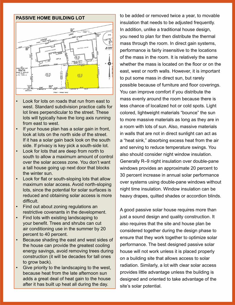
PASSIVE HOME BUILDING LOT
• Look for lots on roads that run from east to west. Standard subdivision practice calls for lot lines perpendicular to the street. These lots will typically have the long axis running from east to west.
• If your house plan has a solar gain in front, look at lots on the north side of the street. If it has a solar gain back look on the south side. If privacy is key pick a south-side lot.
• Look for lots that are deep from north to south to allow a maximum amount of control over the solar access zone. You don’t want a tall house going up next door that blocks the winter sun.
• Look for flat or south-sloping lots that allow maximum solar access. Avoid north-sloping lots, since the potential for solar surfaces is reduced and obtaining solar access is more difficult.
• Find out about zoning regulations an restrictive covenants in the development.
• Find lots with existing landscaping to your benefit. Trees and shrubs can cut air conditioning use in the summer by 20 percent to 40 percent.
• Because shading the east and west sides of the house can provide the greatest cooling energy savings, avoid removing trees during construction (it will be decades for tall ones to grow back).
• Give priority to the landscaping to the west, because heat from the late afternoon sun adds a great deal of heat gain to the house after it has built up heat all during the day.

orientation Naturally, buildings oriented along an east-west axis are more efficient for both winter heating and summer cooling. East-west orientation allows for maximum windows and roof top area for panels for solar capture for heating. This orientation also minimizes east-west exposure to morning and afternoon summer sunlight in the summer. You can employ different building shapes and orientations by combining effective glazing, solar exposure, and shading into the building form. Solar efficiency can also be enhanced by the placement of interior spaces and by the use of clerestories and skylights. Depending upon the site, orientations other than east and west may be desirable. However, you will find that for most climates, an east-west axis is the most efficient for both heating and cooling.
They are many creative ways to use passive solar design even on building lots with limited southern exposure. In Figure 11, the Ross House shows a two story design that uses a large atrium on the southern wall on a lot that is primarily north-south orientation. The owners call it a “southern light box”. According to the builders it uses 1/4 the energy of any of the neighboring homes and is LEED platinum certified. Designed by the firm of Richard Wittschiebe Hand, it is located in Madison, Wisconsin.
floor plans Rooms that are most used and have the greatest heating and lighting requirement should be arrayed along the south face of the building. Rooms that are least used (closets, storage areas, garages) should be placed along the north wall where they can act as a thermal buffer between high-use living space and the cold north side of the building. If a
Figure 11. The Ross house in Madison, Wisconsin uses a two-story atrium to compensate for a limited southern exposure. Windows on the North, East and West are limited for best solar performance.
structure does not have these rooms, then place bedrooms on the north side, since they have less daytime lighting and heating requirements. Consider the use of natural lighting such as clerestories combined with glass partitions to provide lighting to these northern rooms. In addition, consider an open floor plan that can facilitate the flow of air and reduce temperature variations among rooms that do not share a southern exposure.
entryways Entries account for great deal of heat loss especially in small structures during opening and closing of doors. Heat can also be lost by seeping between the door frame and the door, and at windows. Window, door or other wall penetration heat loss (or heat gain in the summer) is called infiltration. To reduce both direct and infiltration losses, recess entry ways to protect against the direct force of prevailing winds. Additional loss reduction can be accomplished by providing a double entry, or vestibule, creating a sealed zone between

the outside and the interior living space. It also reduces the amount of cold or warm air entering the living space whenever someone opens the interior door. This principal is behind the use of revolving doors as access to buildings, since the doors provide an “air lock” for each access to the building. It is why many buildings now have signs requesting that you use the revolving door instead of the standard door.
Figure 13 Ohio State’s entry in the U.S. Department of Energy Solar Decathlon 2011. The major living areas are oriented on an east-west axis along southern wall of building.
An excellent approach to entry ways is to locate them on southern exposures and use a vestibule. In this manner, the vestibule can be used as an indirect gain or “greenhouse” passive solar design where the vestibule both collects heat and provide cooling (Figure 7). Operable vents at the ceiling
and floor levels (both to inside and outside) can be used to regulate the temperature to provide both heating and cooling to the internal space. Because the vestibule is not a “living” space, temperature ranges can be higher than normally tolerated. To prevent overheating in the summer, however, the vestibule requires some form of shading. The best approach to provide an overhang.
windows Windows are the least effective heat flow inhibitors, both in terms of letting heat out in the winter, and letting heat in the summer. When the outside temperature is 30°F and the inside temperature is 68°F, a square foot of single pane glass will lose 20 times as much heat (about 43 BTU’s per hour) as a square foot of 3” thick insulated wall. Because of this heat loss, window sizing and window placement is critical. However, with southern exposure, double and triple-glazed windows can provide a “net” energy gain because the lower insulation value (versus an insulated wall) will easily be offset by the solar gain of the interior space via the solar radiation that passes through the glass. This will be doubly true if some form of window insulation is available at night.
The major expanse of windows in a passive solar structure will be south facing solar windows. Design planning should include considerations such as the impact of heat gain in the summer, views, natural lighting, and privacy requirements. For the most part, Keep window on east, west and north facing walls small. They should be recessed and all should be double-glazed at least. Triple glazing would be better.
For direct gain heating the area of the glazed surface is determined by the duration and severity of winter temperatures; the building size, and the amount of interior thermal storage mass.

You should find a correct balance between these factors in order to avoid large daily temperature fluctuations even in the winter. As a rule (assuming the correct amount of thermal storage mass), plan for 0.19 to 0.38 square feet of south facing glass for each square foot of interior floor area. This should provide enough sunlight to maintain an average temperature between 65°F and 70°F during the winter months in cold climates ( outside average winter temperatures between 20°F and 30°F). In more moderate climates you can achieve the same temperatures with 0.11 to 0.25 square feet of south facing glass (average winter temperatures between 35°F and 40°F).
Location and sizing of glazing is also dependent upon the building layout and types of spaces. Frequently used spaces should have the most windows while infrequently used spaces the least. Windows can be designed smaller with the use of reflectors, or larger by the use of movable insulation, double glazing, and by using wooden sash and frames. The lower heat conductivity of wood can reduce the heat loss around windows by as much as 20 percent.
north walls In an east-west oriented building, a north facing exterior wall will receive little sunlight during the winter and will be a major source of heat loss. You can use several different techniques to minimize this. First, shape the building so that the roof slopes downward from the south to the north wall (Figure 16). This reduces the height of the north face and the area through which heat is lost. This also allows sunlight to reach more area of north side outdoor spaces. Second, if possible, back the building into a sloped hillside or provide a berm, both of which reduce the exposed north area. Possibly
the easiest solution is to locate unheated spaces such as storage or a garage along the north face of the structure.
clerestories & skylights If there is a large gap between the southern wall and the interior thermal mass, then a large expanse of southern exposure glass will not work. The storage masses in direct gain designs must receive direct sunlight, and the further away from the collecting surface, the taller the collecting surface must be because of the sun’s angle. Usually, storage walls should not be set back more than 1.25 to 1.5 times the height of the collecting surface. So if the distance from glazing to wall is 10 feet, the windows should be between 12 and 15 feet tall. (At a maximum an interior thermal storage wall should be no more than 12’ from solar glazing wall). Tall windows will heat a building too much in the summer, and direct sunlight will play havoc on most furniture and interior finishes. Finally, and most important, adjacent structures and/or vegetation may reduce the amount of direct sunlight to the point that a south facing collecting surface at ground level becomes infeasible or seriously reduced. Any one, or combination of these conditions can
Figure 14: Solar tracking skylights can capture and redirect sunlight even on flat roofs.

make south wall heat collection for direct gain problematic. However, these can be easily mitigated by the use of clerestories or skylights. Both of these features admit sunlight at the roof structure of a building and can be used to direct sunlight to a specific interior surface. They can also be used in combination with or as a supplement to a south facing glazed wall. Additionally, they provide for natural light, which can reduce the need and cost of artificial lighting. Clerestories are vertical south facing windows are typically located at roof level. Their advantages are that they allow diffuse lighting into a room; provide privacy; and can be placed almost anywhere on a roof. In addition, you can install
Figure 15: Clerestory windows can reduce need for large expanses of solar glazing. They are often ease to shade from summer sun by awnings or roof overhangs (House designed by University of Maryland for DOE solar decathalon).
more than one set, so each room can have its own source of heat and light. The design should locate them at a distance from a thermal storage wall to allows direct sunlight to hit the wall throughout the winter. This distance should be roughly 1.5 times the height of the wall. Paint ceilings in rooms containing clerestories light in color to reflect or diffuse sunlight into the living space. The use of frosted glass will help to diffuse light and provide privacy. You can use multiple clerestories in large interior spaces to allow maximum admission of sunlight. Be careful that they do not shade each other, so the clerestory roof angle (from horizontal) should be roughly the same angle of the sun at the winter solstice.
Skylights are either horizontal (a flat roof) or pitched at the same angle as the roof slope. In many cases. Horizontal skylights are used with reflectors to increase the intensity of solar radiation and accommodate the sun’s angle of incidence. When they are placed on a pitched roof with a southern exposure they can, however, cause serious overheating. Most of the direct solar radiation admitted will be during the summer months when the sun is at its apex, typically in late afternoon. If used, then large skylights should be provided with external shading devices to prevent heat loss at night and heat gain during the summer months. (Internal blinds and shades will just capture light already in the house and convert it to heat.) Newer skylights (Figure 14) can actually track the sun during the day to provide maximum solar heating as well as a light source that can dramatically reduce interior lighting requirements. If you want natural light, then there are also “solar tubes” that redirect sunlight into just about any space and prevent overheating in the summer.

Figure 16: Example of a house that employs many passive solar design technique to acheive optimal solar performance. From the north side garage to the south roof overhang the house will maximize solar gains and minimize heat losses (insolation).
passive solar checklist1. lot with south facing exposure
2. east west building orientation
3. minimal southern obstructions
4. majority of glazing on southern wall
5. mininimal glazing on northern wall
6. minimal glazing on east-west walls
7. shading on east west exposures
8. roof overhang to block summer sun
9. low wall on north face
10. storage, garage and least used rooms on north walls
11. common rooms (kitchen, living-room) with southern exposure
12. isolated entryway with vestibule
13. no skylights unless they can be shaded from summer sun
14. distance from glazing to thermal mass less than 15 feet
15. clerestories to extend light further into room
16. non-storage walls light colors to refelect light
17. Decidious trees and shrubs to block summer sun
masonry heat storage A thermal mass can provide heating in the winter and cooling in the summer. It does this by absorbing direct sunlight; some is reradiated immediately back into structure but some is stored as latent heat. At night the process reverses as the thermal mass gives up its heat, warming the room by radiation, convection and conduction. If designed correctly, then convection air currents at night can cool the mass during cooler summer nights. During the day the mass absorbs internal heat, cooling a structure. This concept of the ‘diurnal heat capacity’ is defined as the amount of energy per degree swing in temperature stored in the material and returned back to the indoor space during the diurnal cycle per unit surface area.
In almost all the building components, heat transfer takes place through three modes of heat transfer. The external wall surface receives heat through convection from the ambient air, the heat gets transmitted from one side to the other via conduction, and the internal wall transfers the heat via convection to the interior. With passive solar designs, direct radiation plays a much greater role, so concepts like solar absorption and emissivity factor in along with convection and conduction.
Most building materials are evaluated for their U value. The term ‘U’ represents overall thermal conductance from the outside to inside covering all modes of heat transfer. The ‘U- value’ can be defined as the rate of heat flow over unit area of any building component through unit overall temperature difference between both sides of the component. Its units are Watts per meter squared Kelvin (W/m² K). (You can convert this to BTU/
Hour/Ft2/°F by multiplying by 0.176). This means that, if a wall material had a U-Value of 1 W/m² K, for every degree of temperature difference between the inside and outside surface, 1 Watt of heat energy would flow through each meter squared of its surface.
Because this refers to how well an element conducts heat from one side to the other, it is the reciprocal of its thermal resistance (1/R value). Thus, if we calculate the thermal resistance (R-value) of an element, we can simply invert it to obtain the U-Value.
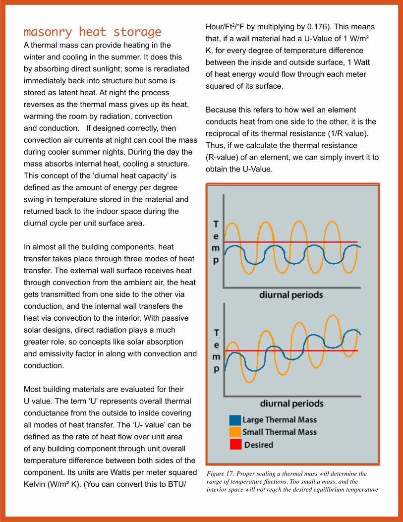
Figure 17: Proper scaling a thermal mass will determine the range of temperature fluctions. Too small a mass, and the interior space will not reqch the desired equilibrium temperature

A thermal mass provides “inertia” against temperature fluctuations, sometimes known as the thermal flywheel effect. The greater the volume of the thermal mass, the greater is its ability to store heat and maintain a uniform temperature. For example, when outside temperatures are fluctuating throughout the day, a large thermal mass will “flatten out” the daily temperature fluctuations, since the thermal mass will absorb thermal energy when the surroundings are higher in temperature than the mass, and give thermal energy back when the surroundings are cooler.
The major design goal of a direct gain passive solar system is to avoid large temperature fluctuations over the day-night cycle. Because the difference between heat gained and heat stored will largely determine the temperature fluctuation over a 24-hour period, this is one of the most important design considerations. It is relatively easy to calculate the amount of heat that will be admitted to a room by any particular collecting surface. It is more difficult to predict the percent of that heat which will be stored. Absorption, emissitivity, and heat capacity all come into play. To have a ‘thermally balanced” house you would need the heat stored in the thermal mass during the day to be equal to heat lost during the night. On average (which will vary based on number of windows, insolation, and insulation), about 65 percent of all heat gained through solar windows during a clear winter day can be lost during the night. This means that during the day, 65 percent of the heat gained must be stored to offset night time losses, and to maintain a relatively even temperature profile. In general terms, the following rules should be observed in regard to design of heat storage systems:
• Masonry and concrete floors, walls and ceilings to be used for heat storage should be a minimum of 4 inches thick.
• *Distribute sunlight over as much of the storage mass surface as possible by using translucent glazing.
• Obtain better thermal control by using a number of small windows to admit sunlight in patches than one large expanse of glass.
• Use light colored surfaces on walls, ceilings, floor to reflect sunlight to thermal storage mass elements.
• Thermal storage mass elements (floors, walls, ceilings) should be dark in color.
• Do not cover Masonry floors used for thermal mass should wall-to-wall carpeting.
• Direct sunlight should not hit dark colored masonry for long periods of time.
• Plan for shading elements to adjust the thermal characteristics of a room.
As a rule of thumb, the most favorable storage occurs when each square foot of sunlight is spread (diffused) over a nine square foot area of storage surface. With this sunlight distribution, the storage mass need not be more than 4 inches thick. If you can only distribute light over a smaller area, then storage efficiency can be increased somewhat by increasing the thickness of the storage mass up to a maximum 8 inches in thickness. Because of limited thermal conductivity (Table 3) of most building materials, however, increasing thickness beyond 8 inches has no beneficial effect on heat storage efficiency. Masonry absorbs heat slowly, and intense sunlight on a small area will have the negative affect by increasing room temperature while not significantly increasing the energy storage rate. It is better to increase heat storage capacity by enlarging the storage surface area and the

distribution of sunlight rather than the thickness of the storage mass.
Higher conductivity means that a material responds more quickly in both absorbing and giving up heat - a quality that increases storage efficiency and decreases temperature fluctuations. As shown in table below most woods are poor conductors compared to stone or concrete. Table 3 shows that gravel concrete has twice the conductivity of light concrete.
Table 3. Thermal Conductivity of Common Building Materials
Material Specific Mass (kgm3)
Thermal Conductivity (W/m2K)
Brick 1600-1900 0.6-0.7Marble 2563 2.2Gravel Concrete 2300-2500 1.7Light Concrete 1600-1900 0.7-0.9Glass 2500 0.8Gypsum 1300 0.5Hardwood 800 0.17Softwood 550 0.14Plywood 700 0.17Floor Tiles 2000 1.5Asphalt 2100 0.7Linoleum 1200 0.17
direct gain water walls Because water’s high specific capacity (Table 2), interior walls of water are much more efficient for thermal collection, storage, and re-radiation than are masonry walls. Water walls should be a dark color to increase heat absorption when exposed to direct sunlight, and will perform well without the problem of heat build-up in the room. The convection process carries heat away from the storage surface quickly, preventing heat build-up, and allowing the storage mass to heat evenly in a relatively short time. If interior water walls receive direct sunlight between the hours of 10:00 a.m. and 2:00 p.m. and are a dark color, you need
about one cubic foot of water for each square foot of solar glazing to maintain comfortable temperatures during winter months. Increasing the volume of water in this ratio to 3 cubic feet of water will decrease daily temperature fluctuations by as much as 6°F.
indirect gain thermal storage Indirect gain systems have different glazing-to-mass values since the solar radiation falls almost exclusively on the storage wall. An indirect wall can provide a high percentage of the heat required in a structure, even in very cold climates. These thermal storage walls can be constructed of either masonry or water. In climates with average winter temperatures between 20°F and 30°F you’ll need between 0.43 and 1.0 square feet of south facing double glazed solar window for each square foot of floor area you are heating. If you use a water wall, then you can reduce the ratio to between 0.31-0.85. In climates where the average winter temperature is between 35°F to 45°F, the figures are 0.22 to 0.60 for masonry walls and 0.16 to 0.43 for water walls. See Table 4.
Correct wall size varies with local conditions and climate; the amount of insulation used; and the latitude of the building site. The first two elements affect the rate of temperature loss from a space, which is influenced by the difference between outside and inside temperatures; and how much insulation is used to slow that rate. Latitude is important because it affects the amount of solar radiation received at the collecting surface on any particular day. For instance, on a clear January day in northern Texas, a square foot of collecting surface will intercept 1883 BTU’s while on the same day, a like amount of surface located in Seattle will intercept only 1537 BTU’s (assuming

the same slope for both surfaces). Local conditions aside, it is generally true that wall size will need to be increased as one moves further north in latitude.
Table 4: Indirect Gain Window SizingAverage outdoor tempera-
ture (°F) and degree days per month
Square feet of glass per square foot of floor area
20° (1,350) 0.6 -1.025° (1,200) 0.51-0.9330° (1,050) 0.43-0.7835° (900) 0.35-0.6040° (750) 0.28-0.4645° (600) 0.22-0.35Degree days are for Dec-JanChoose within a range based on latitude. 35°N use lower number. 48°N use higher number. With poor insulation also use higher number
Other conditions that bear on wall size include obstructions to solar radiation exposure, such as trees, structures, etc.. While unhampered solar access will determine an optimal wall size, reduced or variable access to the sun will require a larger wall area to compensate for reduced solar impact. Sizing should provide enough heat on a clear midwinter day to maintain an average internal temperature of 65°F to 75°F over a 24-hour period. Since thermal storage walls are placed between the solar collecting glazing and the interior space to be heated, overheating is less problematic than with a direct gain design. In very cold climates, or where site conditions allow less than recommended wall size, an indirect gain design can benefit from the use of reflectors, which bounce the sun’s rays to the collection window, thereby increasing the amount of solar radiation moving through the glazing and intercepted by the energy absorber wall. Thermal wall size reduction can occur by as much as 15% if substantial insulation is used at all other wall and roof locations to reduce heat loss from the building.
thermal wall details Aside from the wall area and amount of exposure, the thickness, type of material, and exposed surface color of a wall are main considerations that determine the effectiveness of a wall in meeting the thermal needs of the structure’s occupants. In general, cold climate design benefits from dark, exterior surface colors at the thermal storage wall.
As a variation of the wall which relies on absorption of solar energy at its face and radiation of converted heat at its back, is wall convection. Addition of vents at the upper and lower wall locations (See Figure 7 and Figure 8) provide convected heat to the interior space. Thermal storage wall vents take advantage of the excessive heat build up between the glazing and the surface of the storage wall which can easily exceed 100°F. As warm air moves through the vents, cooler room air is drawn through the lower vents, where it is warmed and rises to repeat the action. This convective cycle directly warms the interior space at the same time heat is being absorbed by the thermal mass of the wall, which will give up its heat to the interior at a later time. This dual action is a benefit for direct heating as well as delayed heating.
Convection air currents can continue 2 to 3 hours after sunset due to the heated exterior surface of the thermal storage wall. Once it stops at night it is important that upper vents are closed when the exterior surface begins to cool. Closing the vents prevents a reverse convection cycle, which removes heat from the space. Vent sizing is about two square feet for each 100 square feet of thermal wall surface equally distributed between top and bottom vents.

Appropriate wall thickness varies with the material used. Again, the idea is to provide comfortable environment while avoiding large and rapid temperature fluctuations. Regardless of the material used, it can be expected that thick walls will produce both minimum and maximum temperatures at different times of day than thin walls, due to the additional time it takes the wall to conduct heat and radiate back into the room. A thicker wall will reduce the temperature variations and will provide longer term storage in the case of cloudy days. General Guidelines are:
• Adobe: 8-12 inches• Brick: 10-14 inches• Concrete: 12-18 inches• Water: 6 inches or more
Water walls are slightly more efficient than masonry walls in collection, retention and re-radiation of heat. They require different design
Figure 18: Cutaway view of a water storage wall that employs inexpensive water barrels for heat storage. Heat can enter interior through conduction through wall or via convection via vents.
consideration i.e. containing the water in an effective, inexpensive and esthetically pleasing way. There are a variety of water encasing systems ranging from manufactured, free standing cylinders to do-it-yourself systems of used, stacked drums, free-standing plastic cylinders, and site-built tanks. The simplest may be just to use 55-gallon water barrels. There would be the thought that metal barrels would perform better, but greenhouse tests revealed no differences whatsoever in heat gain advantage by either type of barrel. Overall, after combining and averaging all of temperature measurements, the water in the plastic barrels and water in metal were virtually identical and black polyethylene barrels are widely available. In the summer, the barrels can also be used for rain storage. A simple design shown in Figure 18 has barrels in racks in an attached indirect gain system. Heat is stored in water in the barrels as well as the brick wall.

greenhouses A greenhouse added to the south side of a building enables it to collect heat due to its solar exposure. The heat can be conducted through a thermal storage wall separating the house and greenhouse, or can be convected to the interior space of the building. The greenhouse serves both as a heat collector and a solarium for people and plants. However, its dual purpose requires a thoughtful design to create ideal conditions for the normal greenhouse operation and passive solar heat. Generally, in cold climates, a greenhouse would use between 0.65 and 1.5 square feet of double-glazed glass surface for each square foot of floor area in the adjacent living space. In more moderate climates this can be reduced to 0.33 and 0.9 square feet. This should provide enough heat to keep the average temperature in the adjacent space between 60°F and 70°F. More data is given in Table 5.
Although it restricts some views from the greenhouse, it is better for it to be recessed into the south facade of the building, thereby minimizing east and west exposures, which have little heat collection but can be a great source of heat loss. Furthermore, this configuration will increase heat transfer through the common wall between the greenhouse and the living space.
You can add a greenhouse for heating purposes to existing frame building, but without a thermal storage mass it will be unable to store heat for use at night. You can adjust for night time heating by transferring via convection (forced) all the greenhouse heat to the main living area’s storage mass (floors, walls, etc.) for deferred use at night. However, this only works in moderately cold climates, because very cold climates require the greenhouse keep residual heat to prevent it and
its contents from freezing at night.
If you are adding a greenhouse to an existing structure, then you can replace the common wall between the greenhouse and the building interior. It should be constructed of thermal mass materials (masonry, water, etc.). The greenhouse side of common walls should be dark in color (better absorber) and should receive maximum sunlight throughout the day. Wall vents and/or operable windows can be used to allow heated air directly into the interior space during the daytime.
Table 5: Greenhouse Window SizingAverage outdoor tempera-
ture (°F) and degree days per month
Square feet of glass per square foot of floor area
20° (1,350) 0.9-1.525° (1,200) 0.78-1.330° (1,050) 0.65-1.1735° (900) 0.53-0.9040° (750) 0.42-0.6945° (600) 0.33-0.53Degree days are for Dec-JanChoose within a range based on latitude. 35°N use lower number. 48°N use higher number. With poor insulation also use higher number
Wall thickness should be same as that provided for in an indirect gain (Trombe) wall. If water is used, its minimum thickness should be 8 inches (or 0.67 cubic feet for each square foot of south-facing glass). Masonry walls can not absorb and transfer heat as fast as a greenhouse can collect it. As a result, temperatures in the greenhouse will fluctuate as much as 60°F on a clear day. To dampen (level out) these fluctuations, extra storage mass (such as masonry units or containers filled with water) can be placed in the greenhouse. These act as an interior heat dampening water wall (1 cubic foot of water for each square foot of south facing glass will reduce temperature fluctuations 25°F to 29°F).

If water is used as the common wall between the greenhouse and the living space, temperature fluctuations will be smaller, and if more than the 0.67 cubic feet of water for each square foot of glass is used in the wall, temperature fluctuations will be further reduced. One approach that combines a greenhouse and rain storage would be to use a water storage tank. The tank shown below holds 650 gallons of water (2.8 tons), and when placed in an attached greenhouse would provide a massive amount of heat storage capacity. In a dry desert climate like the southwest, the tank could also provide cooling in the summertime if there was convective air currents from outside to inside and tank was shaded during the day. In cold climates, you can utilize a heat storage in the form of a rock bin under the building or living space. (Or a thermally heated slab as shown in Figure 9.) This would act as thermal storage of heat collected during the day. Heat transfer can occur
Figure 19: A product called a “waterwall” stores 650 gallons and can be used in a greenhouse as a thermal mass in winter and water storage (rainfall) in summer.
by natural convection if the building is terraced up a slope, or by use of a fan, which would transfer heat to a rock bed located in a crawl space under the floor of the structure. The rock bed should spread across 75 to 100% of the floor area of the structure in cold climates, and 50 to 75% of the floor area in moderate climates. Direct heat from the greenhouse over the rock bed. You need a means of returning cold air from the bottom of the rock bed to the greenhouse. If you have a terraced design, then colder air will naturally settle due to the convective loop cycle. About 1.5 to 3 cubic feet of fist-sized rock is necessary in cold climates and .5 to 1 cubic feet in temperate climates. Rock bin storage has also been used as a part of a cooling system in warmer climates.
roof ponds Although rather rare, another passive solar design is the roof pond. In 1973 a three bedroom, two-bath house with a roof pond was constructed in 1973 in Atascadero, California. This house used black plastic bags of water on the roof for thermal storage. During daylight in the winter, the black bags of water were exposed to solar radiation and then covered with insulation at night. Heat radiated downward into the interior space from the ceiling. During the summer, the process was reversed; the black bags of water were exposed to the night sky and then covered with insulation during the day. This system maintained interior temperatures of 62º - 79ºF without any backup heating or cooling, even though outside temperatures ranged from 26º to 100º F.
The ratio pond surface for each square foot of floor area will vary depending on location, solar exposure and local conditions. A lower ratio should be employed at lower latitudes while the higher ratio should be used at higher latitudes.

For latitudes higher that 36° north, roof ponds require greater solar gain exposure as well as greater protection from loss of gained heat.
In climates where snow is likely, ponds can be placed in a solar attic below the sloping roof with south facing glazing to allow solar gain, and the attic ceiling can be painted a reflective color or sheathed with a reflective material. To increase system performance, glazing for cold climate solar ponds can be dual pane, or the ponds can contain an upper layer inflated air cell.
Because water is so heavy (62 lbs per cubic foot) ceiling structural support for solar ponds should be either structural metal decking (excellent for thermal transfer to spaces below) or thin reinforced concrete decks (more costly, less effective for direct transfer of heat). In constructing the support structure for roof ponds, the layout of the interior space and the weight of the ponds and insulating devices require the assistance of a structural engineer prior to design.
It is important to provide a waterproof layer (membrane, etc.) underneath any pond to provide protection during draining of water for maintenance, bed failure,and weather impacts. The water should be enclosed in ultra-violet light inhibiting (prevents degradation) plastic bags, waterproof structural metal or fiberglass tanks. The top of the water containment system must be transparent and the sides/bottom a dark color. Insulation panels should be constructed so that they can be tightly sealed to prevent infiltration heat loss. In some applications, the insulating panels can also serve as reflectors when open in order to direct more solar to the ponds.
The underside of the support deck serves as an interior ceiling, and all surfaces (including galvanized metal decking) should be painted. Because the system provides a “radiant” ceiling it is important that you use no insulation between the roof pond and the interior space. The one exception is the bathroom, which generates high humidity from showers and tubs. Here, an uninsulated ceiling can result in condensation, so effective water barriers and insulation are critical. Care should be taken to choose tank materials which do not degrade when exposed to sunlight and water, nor are easily damaged from handing and local conditions. You can avoid temperature stratification in the ponds by using a clear top and dark bottom. Sunlight will penetrate the water, be absorbed at the black surface and heat from the bottom will cause a continual convection cycle effect in the pond.
Although as described water ponds can offer a rather simple solution to heating and cooling a structure, the design issues and the basic “fear” of having a large body of water on a roof makes them rather rare. One of the key facts of the roof pond is that you can store a lot of thermal energy in a large volume of water. You can accomplish the same goal with an isolated gain system combined with an insulated water storage tank.
hybrid systems Many times it is necessary to use more than one passive heating design. For instance, a thermal storage wall may block a beautiful view while a direct gain design in the same south wall may create intolerable glare and overheating. In such cases the two designs can be used side by side or in any other configuration (a thermal storage wall on each side of a direct gain window). It is essential, however, to properly size this combination in order to avoid

undesirable temperature fluctuations. About 60 to 75% of the energy striking the collecting surface of a direct gain window can be used in space heating. On the other hand, only about 30 to 45% of the energy striking the collecting surface of a thermal storage wall is transferred to the interior space as heat. It can be seen that the approximate ratio in sizing this combination would be one square foot of direct gain window equals two square feet of thermal storage collecting surface. With these approximations in mind, it should be a relatively easy matter to size various combinations of passive solar designs.
Figure 20. Moveable insulation (white sliding cover) is used to cover a trombe thermal wall at night. The trombe wall uses a phase change material to capture heat. (image from DOE solar decathalon)
cloudy day storage The sun does not always shine. But even on cloudy days passive solar heating designs can continue to collect energy from diffused sunlight. However, the greatly diffuse solar radiation usually does not provide enough energy to keep interior temperatures at 70°F. To compensate, well designed thermal mass systems can be sized to have carryover capacity and when combined with
some auxiliary heating systems, provide enough stored heat for a comfortable environment for a number of cloudy days.
As a rule, direct gain systems can provide comfortable conditions for 1-2 cloudy days if you increase the collecting area by 10-20%, and design the interior walls and floors of solid masonry up to 8 inches thick. If water walls are used in place of masonry, you need to increase the amount of water to two or three cubic feet for each square foot of south facing collecting area.
In contrast, climates where a number of consecutive sunny winter days are common you need to think about for overheating. For example, average temperatures with the above average sizing may result in uncomfortable interior temperatures in excess of 75°F. However, on cloudy days, if the interior temperature drops an average of four degrees per day, comfortable conditions can be maintained for two days with no additional space heating needed. Over sizing a thermal storage wall in very cloudy or foggy climates
( i.e. Seattle) will not work since thicker masonry takes a few days
of sunshine to become fully charged. In climates such as these, overly thick storage masses are likely to result in under-heating. The better approach is to employ large glazed windows with minimum mass thickness so that the system can respond quickly when the sun is available.
Indirect gain systems differ slightly when designing for one or two cloudy days’ storage.

The collector area should be increased by 10 to 20%, and thermal storage walls of greater conductivity be used. This may increase average daily temperatures, but you can control overheating by use of insulating panels or curtains drawn across the interior of the wall to provide temperature control. Built in ventilation systems can be used to control overheating for both indirect gain and direct gain systems..
moveable insulation In all structures, the greatest amount of heat gain is lost through the glazing, either by conduction through the glass or by infiltration around the window frame. Heat loss during the winter reduces the efficiency of all heating systems including passive solar designs. Where possible, you can use movable insulation to cut losses to a minimum. This can even in the form of insulated shades. More complex movable insulation can involve manually operated panels that slide on a track across the glazed area (See Figure 20) to motor driven and temperature activated designs. In hard to reach locations, use mechanical systems. If you often leave a building when insulation should be moved, automatic timers connected to thermostats and/or light sensitive devices can operate, providing appropriate operation of the system. Some machinations can include automatically operated louvers, motor driven panels (roof ponds, etc.) and movable insulation. Whatever the method used, an effective insulation system will greatly increase the efficiency of passive solar designs.
reflectors If partial shading is problematic, collection of solar radiation can be greatly enhanced by the use of reflecting devices. Generally, horizontal reflector should equal in width and one to two times the height of the
glazed opening length should be used for vertical (wall) glazing. South sloping skylights, benefit from reflectors located above the skylight at a tilt angle of roughly 100° from the slope of the roof. The reflector should be roughly equal to the length and width of the skylight. Solar collection can be increased 30-40% when reflectors are used with either vertical, horizontal, or sloping glazing. For greatest efficiency, you need to carefully select the angle of a reflector in relation to the collecting surface. You can test different parameters if you use a program such as Google Sketchup that let you model the sun’s impact on shading over the course of a year.
Figure 21: A reflector directs solar radiation into a thermal mass and increases its heat-capture abilities. In the summer it can be used to cover the glazing to convert space for radiant
In some instances, reflecting surfaces can be used to direct sunlight to an interior storage surface such as a water wall as shown in Figure 21. Reflectors should also be constructed so that they can be used to block heat gain in the summer. As an example, the reflector shown in Figure 21 could be equal to window’s height and attached with a hinge. In the summer it could be

closed and the water wall could be converted to a cooling design if nighttime convection currents were available.
shading Large expanses of south facing glazing can overheat during summer months. You can reduce this overheating by employing a roof overhang carefully designed to shade the glass during the summer (sun higher in the sky) but not block sunlight during the winter (lower in the sky). If you do not want a large overhang, then you can use movable outside shading such as a manual or motor-operated awning. Awnings also have the additional benefit of providing an outside covered space during the summer months. Trellised overhangs that support deciduous vines (vines that lose their leaves in the winter) are another way to block sunlight in the summer and admit sunlight in early spring. Overhangs should be equal in length to roughly one fourth the height of the window opening in southern latitudes and one-half the height of the opening in northern latitudes. The projection of the overhang that will be adequate (which provides 100% shading at noon on June 21) at your particular latitudes can be quickly calculated by using the following formula:
Projection=windowopening(height)/F
Table 6: Shade Factor for Different LatitudesNorth Latitude F Factor28° 5.6-11.132° 4.0-6.336° 3.0-4.540° 2.5-3.444° 2.0-2.748° 1.7-2.252° 1.5-1.856° 1.3-1.8
Fixed louvered awnings are another way to automatically control sunlight over the course of the year. As shown below, a fixed set of louvers offset about two feet from the front windows control the amount of light admitted into the house. The width and depth of the individual louvers and the distance to the windows is set so that on June 23, no light penetrates the windows at all, but on December 21, light travels all the way to the back of the space.
Figure 22: Fixed louvers can control the amount of sunlight in winter and summer if the angle of the angle of the louvers are calculated based on latitude (Ross House Madison, WI).
Another way to modify the amount of solar radiation reaching a solar storage wall is to employ operable louvers. These should be installed externally. Internal louvers or blinds just capture the heat already in the building. In addition, external operable shutters and blinds permit you to adjust for variations in the weather and grant you some forgiveness for any initial design errors in your passive solar design. If a space is overheating all you need is to change is the angle of the louvers. If under heating, change the angle to permit more light to pass. Furthermore, they can have a large impact of the cooling loads of a building. The two graphs
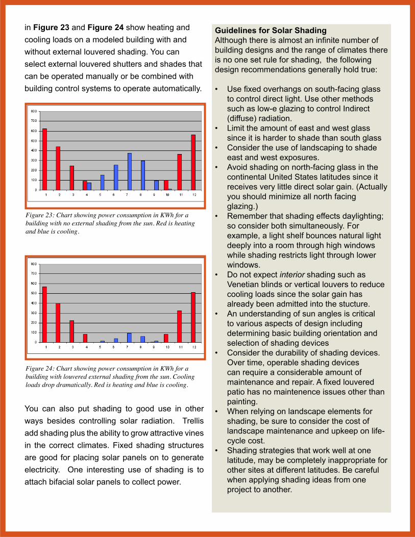
in Figure 23 and Figure 24 show heating and cooling loads on a modeled building with and without external louvered shading. You can select external louvered shutters and shades that can be operated manually or be combined with building control systems to operate automatically.
Figure 23: Chart showing power consumption in KWh for a building with no external shading from the sun. Red is heating and blue is cooling.
Figure 24: Chart showing power consumption in KWh for a building with louvered external shading from the sun. Cooling loads drop dramatically. Red is heating and blue is cooling.
You can also put shading to good use in other ways besides controlling solar radiation. Trellis add shading plus the ability to grow attractive vines in the correct climates. Fixed shading structures are good for placing solar panels on to generate electricity. One interesting use of shading is to attach bifacial solar panels to collect power.
Guidelines for Solar ShadingAlthough there is almost an infinite number of building designs and the range of climates there is no one set rule for shading, the following design recommendations generally hold true:
• Use fixed overhangs on south-facing glass to control direct light. Use other methods such as low-e glazing to control Indirect (diffuse) radiation.
• Limit the amount of east and west glass since it is harder to shade than south glass
• Consider the use of landscaping to shade east and west exposures.
• Avoid shading on north-facing glass in the continental United States latitudes since it receives very little direct solar gain. (Actually you should minimize all north facing glazing.)
• Remember that shading effects daylighting; so consider both simultaneously. For example, a light shelf bounces natural light deeply into a room through high windows while shading restricts light through lower windows.
• Do not expect interior shading such as Venetian blinds or vertical louvers to reduce cooling loads since the solar gain has already been admitted into the stucture.
• An understanding of sun angles is critical to various aspects of design including determining basic building orientation and selection of shading devices
• Consider the durability of shading devices. Over time, operable shading devices can require a considerable amount of maintenance and repair. A fixed louvered patio has no maintenence issues other than painting.
• When relying on landscape elements for shading, be sure to consider the cost of landscape maintenance and upkeep on life-cycle cost.
• Shading strategies that work well at one latitude, may be completely inappropriate for other sites at different latitudes. Be careful when applying shading ideas from one project to another.
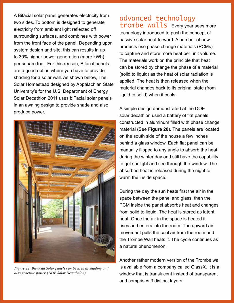
A Bifacial solar panel generates electricity from two sides. To bottom is designed to generate electricity from ambient light reflected off surrounding surfaces, and combines with power from the front face of the panel. Depending upon system design and site, this can results in up to 30% higher power generation (more kWh) per square foot. For this reason, Bifacal panels are a good option where you have to provide shading for a solar wall. As shown below, The Solar Homestead designed by Appalachian State University’s for the U.S. Department of Energy Solar Decathlon 2011 uses biFacial solar panels in an awning design to provide shade and also produce power.
Figure 22: BiFacial Solar panels can be used as shading and also generate power. (DOE Solar Decathalon).
advanced technology trombe walls Every year sees more technology introduced to push the concept of passive solar heat forward. A number of new products use phase change materials (PCMs) to capture and store more heat per unit volume. The materials work on the principle that heat can be stored by change the phase of a material (solid to liquid) as the heat of solar radiation is applied. The heat is then released when the material changes back to its original state (from liquid to solid) when it cools.
A simple design demonstrated at the DOE solar decathlon used a battery of flat panels constructed in aluminum filled with phase change material (See Figure 20). The panels are located on the south side of the house a few inches behind a glass window. Each flat panel can be manually flipped to any angle to absorb the heat during the winter day and still have the capability to get sunlight and see through the window. The absorbed heat is released during the night to warm the inside space.
During the day the sun heats first the air in the space between the panel and glass, then the PCM inside the panel absorbs heat and changes from solid to liquid. The heat is stored as latent heat. Once the air in the space is heated it rises and enters into the room. The upward air movement pulls the cool air from the room and the Trombe Wall heats it. The cycle continues as a natural phenomenon.
Another rather modern version of the Trombe wall is available from a company called GlassX. It is a window that is translucent instead of transparent and comprises 3 distinct layers:

1. A prismatic layer which reflects summer solar radiation (>40°) and allows winter solar radiation to pass through2. A low E tempered safety glass3. The central heat storage module consisting of phase change materials in the form of salt hydrate crystals.
The salt hydrate is a phase change material (PCM) that stores solar thermal radiation by melting to a liquid state. The latent heat energy is radiated back into the interior of the building when temperatures drop and the salt resolidifies. The internal prism minimizes the heat energy reflected (g-value), thereby maximizing solar gains during the winter. The solar radiation that passes through charges up the GlassX PCM core during the day, which it then radiates out at night as the PCM returns to solid phase. This creates an average reduction of heating load of a building by 150-200 kWh/m2 per year on heating days. In the summer, the prism reflects solar radiation so the PCM core does not heat up.
Figure 23: Summer sun high in the sky >(40) so prisims totally reflect all of the sun so phase change material won’t heat up
Figure 24: Winter sun low in in the sky <30% so solar spectrum will pass through to phase change cells (in gray).
When solid, the PCM transmits about 25% of visible light and about 40% in its liquid state. These salt hydrates crystals are hermetically sealed in grey polycarbonate containers. The polycarbonate spacers between the layers give the glass an Venetian blind look. These characteristics maintain a heat transmission coefficient or U-value of 0.08 Btu/F-ft2-hr (the equivalent of an R12 wall). This type of window is highly efficient because the system has no threshold losses; solar energy is gained even in the case of diffuse solar radiation.
PhaseChangingDrywallAvailable in Europe and in testing in the United States is a new category of building products called phase-changing drywall. Embedded in the drywall are small micro spheres that melt and then resolidify based on heat input. The process of solidifying releases heat. The idea is that heat from the sun during the day will be stored in the wallboard, and then released at night to keep the space warm. It will both help prevent overheating during the day and help reduce heating costs at night.

passive solar retrofit
Most of the techniques in this guide apply to construction of new homes. Unfortunately, there are tens of millions of existing structures in the United States where you cannot directly apply these practices. Most of these homes have an expected “lifetime” of 50 or more years, meaning that they will continue to consume non-renewable energy, energy that is becoming more expensive by the year, for decades more. One alternative, however, is to retrofit an existing home with solar thermal panels. If mounted on a roof or other surface with a southern exposure, then they can provide most of the daytime heating requirements of a home on a sunny day. They capture solar radiation in the form of heat for immediate use. Most homes, however, do not have a thermal mass to store it. Walls, furniture, and other surface can store some of the solar radiation however. ZonBak
flexible solar thermal panels are lightweight solar thermal panels that can mount on a roof,
wall, or any other surface. By adding standard air ducts, the heat they generate can be channeled into any room. When the sun shines, they produce heat. The total amount they
produce, and how much you can expect your heating bill to decline will be based on many attributes such as house location (number of sunny days), orientation (angle of pannels to acheive maximum solar gain), but mostly by square footage. Since they are so light and
inexpensive you can install dozens of of square meters at the cost of a one or two photovoltaic panels. Each square meter can produce 4kWh (13,000 BTUs) per an average sunny day based on location. That is typically enough to heat a 10’ x 12’ room (120 ft2). Install 20 square meters that’s enough to heat 2400 ft2. These savings are delivered year in and year out and dramaticaly reduce use of non- renewable energy.
Ducting in attic moves heat from ZonBak panels to rooms throughout the house. Heat moved through panels via forced hot air convection (duct fan). If scaled correctly, panels provide all of the required daytime heat.
A typical ranch-style house with three 30’ ZonBak flexible solar thermal panels to generate passive solar heat. Each panel weighs less than 20 lbs.
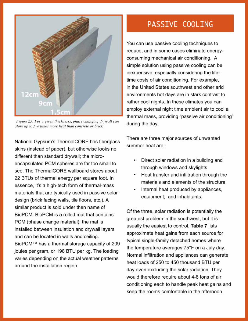
Figure 25: For a given thicknesss, phase changing drywall can store up to five times more heat than concrete or brick
National Gypsum’s ThermalCORE has fiberglass skins (instead of paper), but otherwise looks no different than standard drywall; the micro-encapsulated PCM spheres are far too small to see. The ThermalCORE wallboard stores about 22 BTUs of thermal energy per square foot. In essence, it’s a high-tech form of thermal-mass materials that are typically used in passive solar design (brick facing walls, tile floors, etc.). A similar product is sold under then name of BioPCM: BioPCM is a rolled mat that contains PCM (phase change material); the mat is installed between insulation and drywall layers and can be located in walls and ceiling. BioPCM™ has a thermal storage capacity of 209 joules per gram, or 198 BTU per kg. The loading varies depending on the actual weather patterns around the installation region.
PASSIVE COOLING
You can use passive cooling techniques to reduce, and in some cases eliminate energy- consuming mechanical air conditioning. A simple solution using passive cooling can be inexpensive, especially considering the life-time costs of air conditioning. For example, in the United States southwest and other arid environments hot days are in stark contrast to rather cool nights. In these climates you can employ external night time ambient air to cool a thermal mass, providing “passive air conditioning” during the day.
There are three major sources of unwanted summer heat are:
• Direct solar radiation in a building and through windows and skylights
• Heat transfer and infiltration through the materials and elements of the structure
• Internal heat produced by appliances, equipment, and inhabitants.
Of the three, solar radiation is potentially the greatest problem in the southwest, but it is usually the easiest to control. Table 7 lists approximate heat gains from each source for typical single-family detached homes where the temperature averages 75°F on a July day. Normal infiltration and appliances can generate heat loads of 250 to 450 thousand BTU per day even excluding the solar radiation. They would therefore require about 4-8 tons of air conditioning each to handle peak heat gains and keep the rooms comfortable in the afternoon.
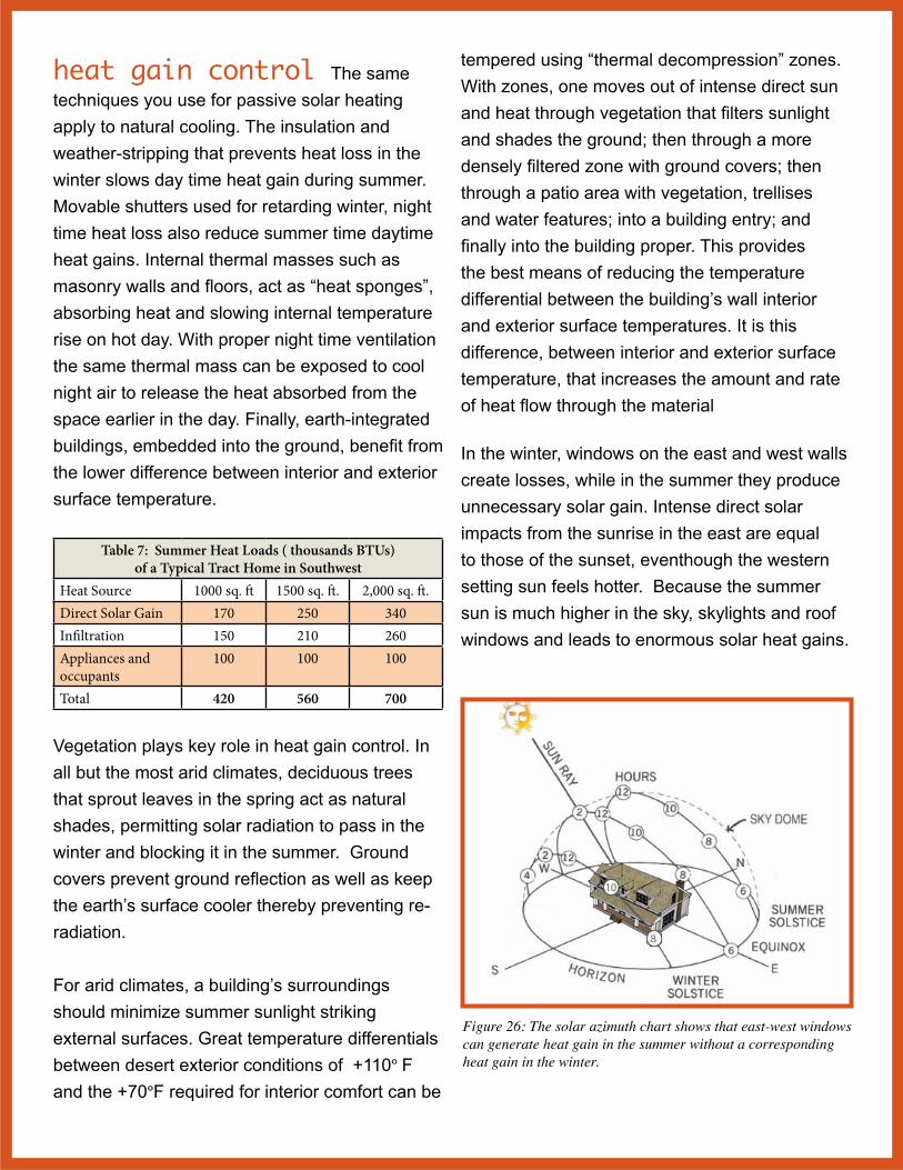
heat gain control The same techniques you use for passive solar heating apply to natural cooling. The insulation and weather-stripping that prevents heat loss in the winter slows day time heat gain during summer. Movable shutters used for retarding winter, night time heat loss also reduce summer time daytime heat gains. Internal thermal masses such as masonry walls and floors, act as “heat sponges”, absorbing heat and slowing internal temperature rise on hot day. With proper night time ventilation the same thermal mass can be exposed to cool night air to release the heat absorbed from the space earlier in the day. Finally, earth-integrated buildings, embedded into the ground, benefit from the lower difference between interior and exterior surface temperature.
Table 7: Summer Heat Loads ( thousands BTUs) of a Typical Tract Home in Southwest
Heat Source 1000 sq. ft 1500 sq. ft. 2,000 sq. ft.Direct Solar Gain 170 250 340Infiltration 150 210 260Appliances and occupants
100 100 100
Total 420 560 700
Vegetation plays key role in heat gain control. In all but the most arid climates, deciduous trees that sprout leaves in the spring act as natural shades, permitting solar radiation to pass in the winter and blocking it in the summer. Ground covers prevent ground reflection as well as keep the earth’s surface cooler thereby preventing re-radiation.
For arid climates, a building’s surroundings should minimize summer sunlight striking external surfaces. Great temperature differentials between desert exterior conditions of +110° F and the +70°F required for interior comfort can be
tempered using “thermal decompression” zones. With zones, one moves out of intense direct sun and heat through vegetation that filters sunlight and shades the ground; then through a more densely filtered zone with ground covers; then through a patio area with vegetation, trellises and water features; into a building entry; and finally into the building proper. This provides the best means of reducing the temperature differential between the building’s wall interior and exterior surface temperatures. It is this difference, between interior and exterior surface temperature, that increases the amount and rate of heat flow through the material
In the winter, windows on the east and west walls create losses, while in the summer they produce unnecessary solar gain. Intense direct solar impacts from the sunrise in the east are equal to those of the sunset, eventhough the western setting sun feels hotter. Because the summer sun is much higher in the sky, skylights and roof windows and leads to enormous solar heat gains.
Figure 26: The solar azimuth chart shows that east-west windows can generate heat gain in the summer without a corresponding heat gain in the winter.
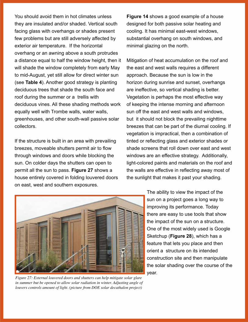
You should avoid them in hot climates unless they are insulated and/or shaded. Vertical south facing glass with overhangs or shades present few problems but are still adversely affected by exterior air temperature. If the horizontal overhang or an awning above a south protrudes a distance equal to half the window height, then it will shade the window completely from early May to mid-August, yet still allow for direct winter sun (see Table 4). Another good strategy is planting deciduous trees that shade the south face and roof during the summer or a trellis with deciduous vines. All these shading methods work equally well with Trombe walls, water walls, greenhouses, and other south-wall passive solar collectors.
If the structure is built in an area with prevailing breezes, moveable shutters permit air to flow through windows and doors while blocking the sun. On colder days the shutters can open to permit all the sun to pass. Figure 27 shows a house entirely covered in folding louvered doors on east, west and southern exposures.
Figure 27: External louvered doors and shutters can help mitigate solar glare in summer but be opened to allow solar radiation in winter. Adjusting angle of louvers controls amount of light. (picture from DOE solar decathalon project)
Figure 14 shows a good example of a house designed for both passive solar heating and cooling. It has minimal east-west windows, substantial overhang on south windows, and minimal glazing on the north.
Mitigation of heat accumulation on the roof and the east and west walls requires a different approach. Because the sun is low in the horizon during sunrise and sunset, overhangs are ineffective, so vertical shading is better. Vegetation is perhaps the most effective way of keeping the intense morning and afternoon sun off the east and west walls and windows, but it should not block the prevailing nighttime breezes that can be part of the diurnal cooling. If vegetation is impractical, then a combination of tinted or reflecting glass and exterior shades or shade screens that roll down over east and west windows are an effective strategy. Additionally, light-colored paints and materials on the roof and the walls are effective in reflecting away most of the sunlight that makes it past your shading.
The ability to view the impact of the sun on a project goes a long way to improving its performance. Today there are easy to use tools that show the impact of the sun on a structure. One of the most widely used is Google Sketchup (Figure 28), which has a feature that lets you place and then orient a structure on its intended construction site and then manipulate the solar shading over the course of the year.

Figure 28: Programs like Google Sketchup let you visualize shading over the course of a day and over the seasons.
convective cooling With mild summer temperatures, appropriate shading should suffice to keep room temperatures comfortable in houses. But there are many other regions of the southwest, particularly the desert areas, where you will need incremental cooling techniques. One of the most prevalent is “convective” cooling methods, those which use the prevailing winds and natural, gravity-induced convection to ventilate a house at the appropriate times of the day.
The oldest, straightforward convective method admits cool night air to drive out the warm air. If breezes are predominant, high vents or open windows on the leeward side (away from prevailing breeze) will let the hottest air, located near the ceiling, escape. Roof vents such as turbine fans are another option. The cooler night air sweeping in through low open vents or windows on the windward side will replace this hot air and bring relief. (In place of air conditioning, many homes can use whole house fans that draw cool night air through windows
and exhaust it out through the attic). With passive methods, to get the best cooling rates, leeward openings should have substantially larger total area (50% to 100% larger) than those on the windward side of the house. If there are only light breezes at the site, you can use natural convection to ventilate and cool a house as long as the outdoor air is cooler than the indoor air
at the peak of the house. Since warm air rises, vents located at high points in the interior will allow warm air to escape while cooler outdoor air flows in through low vents to replace it. The coolest air around a house is usually found on the north side, especially if this area is well shaded by trees or shrubs and has water features.
Figure 29: Before central air conditioning homes were designed for passive cooling. The Vanderbilt mansion in Hyde Park, NY built in 1888 uses a central atrium and vented skylight to cool the mansion. In the summer vents where opened at the periphery of the skylight which provided for convection air currents throughout the structure.

Cool air intake vents are best located as low as possible on the north side. The greater the height difference between the low and high vents, the faster the flow of natural convection and the more heat mitigation will occur. There are two basic ways to enhance the convective cooling rate: 1) increase the volume (V) of air escaping per minute, or 2) bring in cooler air. If ∆T is the temperature difference between exiting indoor air and incoming outdoor air, the overall cooling rate in BTU’s per hour is given by the simple equation:
Cooling rate = 1.08 x V x ∆T
where V is the volume of air escaping in cubic feet per minute.
Table 8: Temperature Difference, ∆TAir Flow, V 5°F 10°F 15°F 20°F100 cfm 0.5 1.1 1.6 2.2500 cfm 2.7 5.4 8.1 10.81000 cfm 5.4 10.8 16.2 21.62000 cfm 10.8 21.6 32.4 43.2* in thousands of BTU’s/hour
Table 8 contains sample values of the cooling rate for selected air flow rates and temperature differences. For example, an air flow velocity of 1-2 feet/sec. through a vent of 10 square feet will result in air flow rates between 500 and 1000 cubic feet per minute. If the incoming air is 10 degrees cooler than the indoor air, the overall cooling rate will be about 5 to 10 thousand BTU’s per hour. Increasing vent area to improve convection is only helpful to a point. Turbine vents at the roof peak are one way to improve the cooling rate. Even gentle breezes flowing up and over the roof peak create an upward suction that draws out warm interior air.
An even better approach is to use solar radiation
to induce a more rapid air flow. One of the many possible approaches, uses a Trombe wall vented to the outside. Sunlight striking the concrete wall will heat the air in the space between glass and wall to temperatures above 150°F. This very hot air rises quickly, drawing cool air into the house through low vents on the north wall.
Figure 30: Mayan architecture uses natural convection cooling to great effect. The peaked roofs create rapid horizontal air flow from prevailing breezes at top of ceilings that extract hot air from from the structure (Coanda effect). The design technique provides comfortable year-round temperatures even in the tropics.
Figure 9 shows a Trombe wall vented into the house. If you were to add a duct vented to the exterior, than this wall would pull air from inside and vent it to the outside via natural convection.
A similar technique has been used in the middle east for decades. A black painted chimney, or “solar chimney” can serve many purposes. Direct gain warms air inside the chimney causing it to rise out the top and drawing air in from the bottom. This drawing of air can be used to ventilate a home. Frequently, they can induce air velocities of more than 1-2 feet per second. The chimney has to be higher than the roof level, and has to be constructed on the wall

facing the direction of the sun. Absorption of heat from the sun can be increased by using a glazed surface on the side facing the sun. Heat absorbing material can be used on the opposing side. The size of the heat-absorbing surface is more important than the diameter of the chimney. Openings of the vents in the chimney should face away from the direction of the prevailing wind.
Another convective cooling strategy is drawing outdoor air through ducts buried in the ground. Tubes or air-ducts made of material that allows thermal transfer to the ground extract the cooler subsurface temperatures. Warm outdoor air entering the duct exchanges its heat to the cooler earth. However, you need to address thermal saturation of the ground through landscaping and watering, thereby eliminating the gained thermal energy from the duct/earth transfers. Though condensation is rarely a problem in dry climates, such ducts should be sloped slightly downhill and have adequate drainage. When properly built and sized, these underground tubes can supply cool air during mid afternoon even in the hottest climates. radiative cooling Exterior water wall and roof pond systems are very effective summer cooling strategies. Insulation panels remain closed by day to block unwanted solar heat. The ponds act as “thermal sponges”, absorbing room heat conducted through the interior ceiling (metal deck) supporting them. At night, the insulation panels can roll back, exposing the ponds to the cooler night air and breezes. The ponds will lose heat by radiation to the night sky and by natural convection to the air.
Cloud cover can interfere with the cooling performance of any roof pond system. So, roof ponds will be less effective in coastal
areas where there is dense fog in the evening. Fortunately, coastal areas need little cooling during the summer. So in summary, roof pond systems are particularly effective in regions of low humidity and clear summer nights such as the southwest. Unfortunately, in these geographic regions water is scarce so roof ponds or similar approaches lose most of their appeal.
evaporative cooling When water evaporates it absorbs a large amount of heat from its surroundings (about 1000 BTU per pound of water evaporated). The most familiar example of this is the cooling effect of perspiration on the human skin. In hot humid climates evaporative cooling is less effective because of the high moisture content of the surrounding air. Regardless of the humidity, the evaporation rate is raised as you increase the air movement. Both of these facts can be applied to natural cooling of structures.
Evaporative methods can improve performance of convective cooling systems. One way of doing this is to bring the outdoor air into the house through a moist filter or pad. The familiar evaporative cooler, predecessor to the air conditioner uses a motor-driven fan to force air distribution across a wet surface. You can experience a similar effect if you place a moist towel over a standard house fan. These evaporative cooling strategies are well suited to those areas of the southwest with the most severe cooling requirements. They are most effective where the humidity is low and there is access to a large volume of water.
With advanced planning, one simple technique for passive evaporative cooling can employ a swimming pool. An open pool of water on the

north side of a house is shaded from the summer sun but exposed to the cool north sky both day and night. Evaporation from the pool surface, aided by radiation and natural convection, can keep the water in the pool an average 30°F below the outside air temperature even on a hot summer day. In addition, the water at the bottom of the pool will be cooler than the water at the top due to convection currents (cold water sinks because it is more dense). Exchanging heat at the bottom of a pool (Figure 31) therefore can extract massive amounts of cold air via passive evaporative cooling at the surface of the pool and conduction from the pool to cooling ducts. The heat exchange to the pool will heat the water, making the water warmer and extending the pool’s season. If the pool is built on a slope, then ducting can run from outside under pool, into structure. Convection air flow out through an exit on the roof will provide cooling via a natural process.
Figure 31: A swimming pool can be used as a source of evaoprative cooling if built with under-pool ducting for forced air convection.
With all evaporative cooling methods, it is important to maximize airflow across the exposed water.
Fresh air must be continually available to replace the humid air being built up near or over the water. Failing this, air will be quickly saturated with water vapor, and the evaporation and cooling rates will decline abruptly. Lips, edges and other structures or buildings that could block or deflect prevailing winds away from the water surfaces should be studiously avoided. That is why an “infinity pool” that brings the water surface above ground level will have better cooling properties than a standard in-ground pool.
In many areas of the southwest which are considered hot, arid zones, periods of higher humidity renders mechanical evaporative cooling ineffective. One possible solution is to employ a two-stage evaporative cooling system. On the first stage, cooling is accomplished by pre-cooling ambient air before further cooling via evaporation. The cool air that enters the structure is exhausted, typically through areas of heat gain such as the attic. Precooling may be accomplished at night via a cooled thermal mass such as a rock bed through which air is drawn. The second stage, evaporative cooling, is accomplished via a standard commercial evaporative cooler. This type of system is best suited for new construction because it requires a rock bed, which is most effectively located beneath the structure. The comfort levels that can be attained with this approach is similar to that of refrigerated air-conditioning systems. These evaporative air conditioning systems are well-suited to the southern (temperate) part of Australia as well as the Southwest United States. In dry, arid
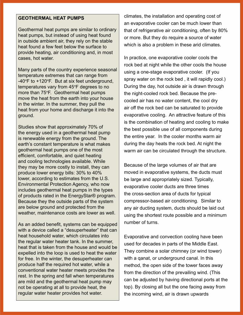
GEOTHERMAL HEAT PUMPS Geothermal heat pumps are similar to ordinary heat pumps, but instead of using heat found in outside ambient air, they rely on the stable heat found a few feet below the surface to provide heating, air conditioning and, in most cases, hot water.
Many parts of the country experience seasonal temperature extremes that can range from -40°F to +120°F. But at six feet underground, temperatures vary from 45°F degrees to no more than 75°F. Geothermal heat pumps move the heat from the earth into your house in the winter. In the summer, they pull the heat from your home and discharge it into the ground.
Studies show that approximately 70% of the energy used in a geothermal heat pump is renewable energy from the ground. The earth’s constant temperature is what makes geothermal heat pumps one of the most efficient, comfortable, and quiet heating and cooling technologies available. While they may be more costly to install, they can produce lower energy bills: 30% to 40% lower, according to estimates from the U.S. Environmental Protection Agency, who now includes geothermal heat pumps in the types of products rated in the EnergyStar® program. Because they the outside parts of the system are below ground and protected from the weather, maintenance costs are lower as well.
As an added benefit, systems can be equipped with a device called a “desuperheater” that can heat household water, which circulates into the regular water heater tank. In the summer, heat that is taken from the house and would be expelled into the loop is used to heat the water for free. In the winter, the desuperheater can produce half the required hot water, while a conventional water heater meets provides the rest. In the spring and fall when temperatures are mild and the geothermal heat pump may not be operating at all to provide heat, the regular water heater provides hot water.
climates, the installation and operating cost of an evaporative cooler can be much lower than that of refrigerative air conditioning, often by 80% or more. But they do require a source of water which is also a problem in these arid climates.
In practice, one evaporative cooler cools the rock bed at night while the other cools the house using a one-stage evaporative cooler. (If you spray water on the rock bed , it will rapidly cool.) During the day, hot outside air is drawn through the night-cooled rock bed. Because the pre-cooled air has no water content, the cool dry air off the rock bed can be saturated to provide evaporative cooling. An attractive feature of this is the combination of heating and cooling to make the best possible use of all components during the entire year. In the cooler months warm air during the day heats the rock bed. At night the warm air can be circulated through the structure.
Because of the large volumes of air that are moved in evaporative systems, the ducts must be large and appropriately sized. Typically, evaporative cooler ducts are three times the cross-section area of ducts for typical compressor-based air conditioning. Similar to any air ducting system, ducts should be laid out using the shortest route possible and a minimum number of turns.
Evaporative and convection cooling have been used for decades in parts of the Middle East. They combine a solar chimney (or wind tower) with a qanat, or underground canal. In this method, the open side of the tower faces away from the direction of the prevailing wind. (This can be adjusted by having directional ports at the top). By closing all but the one facing away from the incoming wind, air is drawn upwards
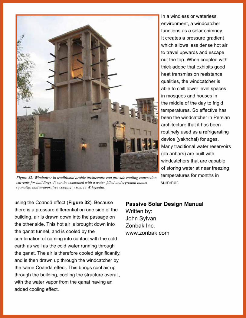
Figure 32: Windtower in traditional arabic archtecture can provide cooling convection currents for buildings. It can be combined with a water-filled underground tunnel (qanat)to add evaporative cooling. (source Wikepedia)
using the Coandă effect (Figure 32). Because there is a pressure differential on one side of the building, air is drawn down into the passage on the other side. This hot air is brought down into the qanat tunnel, and is cooled by the combination of coming into contact with the cold earth as well as the cold water running through the qanat. The air is therefore cooled significantly, and is then drawn up through the windcatcher by the same Coandă effect. This brings cool air up through the building, cooling the structure overall, with the water vapor from the qanat having an added cooling effect.
In a windless or waterless environment, a windcatcher functions as a solar chimney. It creates a pressure gradient which allows less dense hot air to travel upwards and escape out the top. When coupled with thick adobe that exhibits good heat transmission resistance qualities, the windcatcher is able to chill lower level spaces in mosques and houses in the middle of the day to frigid temperatures. So effective has been the windcatcher in Persian architecture that it has been routinely used as a refrigerating device (yakhchal) for ages. Many traditional water reservoirs (ab anbars) are built with windcatchers that are capable of storing water at near freezing temperatures for months in summer.
Passive Solar Design ManualWritten by:John SylvanZonbak Inc.www.zonbak.com


