passive solar design handbook -
90
United States Air Force Passive Solar Handbook Introduction To Passive Solar Concepts Volume I
Transcript of passive solar design handbook -

United States Air Force
Passive Solar HandbookIntroduction To Passive Solar Concepts
Volume I
Daniel Friedman
Text Box
Click anywhere in the top of this page to see online articles on Solar Energy, Wind Turbines, Energy Savings and Building Inspection Diagnosis & Repair Guides at InspectAPedia.com
Foreword
The United States Air Force is committed to energy efficiencyand the use of renewable forms of energy in all of its facilitieswhen shown to be reliable and cost effective. In its response tothe Military Construction Codification Act of 10 USC 2801,Executive Order 12003 and Office of the Secretary of Defensedirectives, the Air Force has implemented numerous policies andprocedures to significantly reduce the usage of fossil fuel derivedenergy. Since the oil embargo of the early 1970’s, the Air Forcehas encouraged and demonstrated the integration of a variety ofenergy conserving features, including solar applications, in itsfacilities. Passive solar systems represent one type of solarapplication that can be used in almost all facilities to improvetheir energy efficiency and to lower their energy costs.
The audience for this five-volume passive solar handbook is thenumerous Air Force personnel and others responsible forprogramming, planning, designing, supervising construction,commissioning, and operating and maintaining Air Forcecommercial-type facilities worldwide. This handbook wasdeveloped in response to MAJCOM and base needs forinformation on the integration of passive solar systems into newAir Force commercial-type facilities.
The goal of the Air Force Passive Solar Handbook series is tointegrate passive solar concepts into the Air Force planning,programming, design, construction, and operation processes forcommercial-type facilities.
The five volumes of the Passive Solar Handbook are as follows:
Volume I: Introduction To Passive Solar ConceptsVolume II: Comprehensive Planning GuideVolume III: Programming GuideVolume IV Passive Solar Design (proposed)Volume V: Construction Inspection (proposed)
This is the first volume of the series.
Joseph A. Ahearn, Major General, USAFDirector of Engineering and Services
Introduction To Passive Solar Concepts i
Acknowledgements
This handbook was written by Architectural Energy Corporationunder contract to the United States Air Force EngineeringDirectorate. We wish to acknowledge the support and technicalassistance of Refugio Fernandez, HQ USAF/LEEDE, andCharles F. Lewis, HQ USAF/LEEDX. On their behalf, we wish toacknowledge others throughout the United States Air Force whoreviewed earlier drafts of this handbook.
Architectural Energy Corporation staff responsible for theresearch, building energy simulations, software development,writing, graphic design, layout, proofreading and camera-readyproduction include Michael J. Holtz, Claude L. Robbins, DonaldJ. Frey, David N. Wortman, Peter A. Oatman, Joan M.Gregerson, Chris Mack, Linda J. Ross, and Tracy Ashleigh. P.S.Computer Graphics Inc. assisted with the camera-readyproduction and coordinated the color separation and printing.
We would also like to thank Dr. Subrato Chandra and Dr. RossMcCluney of the Florida Solar Energy Center for their help inour analysis of warm-humid climates.
Michael J Holtz, A.I.A. Pres identArchitectural Energy Corporation
Additional copies of this handbook may be obtained from:
Architectural Energy Corporation2540 Frontier Avenue, Suite 201Boulder, Colorado 8 0 3 0 1 U S A(303) 444-4149 FAX (303) 444-4304
i i Volume I
Table of Contents
Foreword
Acknowledgements
1.0
2.0
3.0
4.0
5.0
Passive Solar Concepts 1
Introduction 1Passive Solar System Components 2Passive Heating 4Passive Cooling 10Daylighting 13Conclusions 19
Energy and Site Planning 20
Introduction 20Site Planning For Passive Heating 21Site Planning For Passive Cooling 25Planning For Daylighting 28Building Orientation and Shape 29
Energy and Buildings 32
Introduction 32Climate and Buildings 33Energy Responsive Buildings 37Energy Costs 43
Suggested Additional Reading 47
Glossary of Terms 50
Appendix A: USAF Climate Regions
Appendix B: Building-Type Category Codes
Index
59
71
79
Introduction To Passive Solar Concepts i i i

i v Volume I
Passive Solar Concepts 1.0
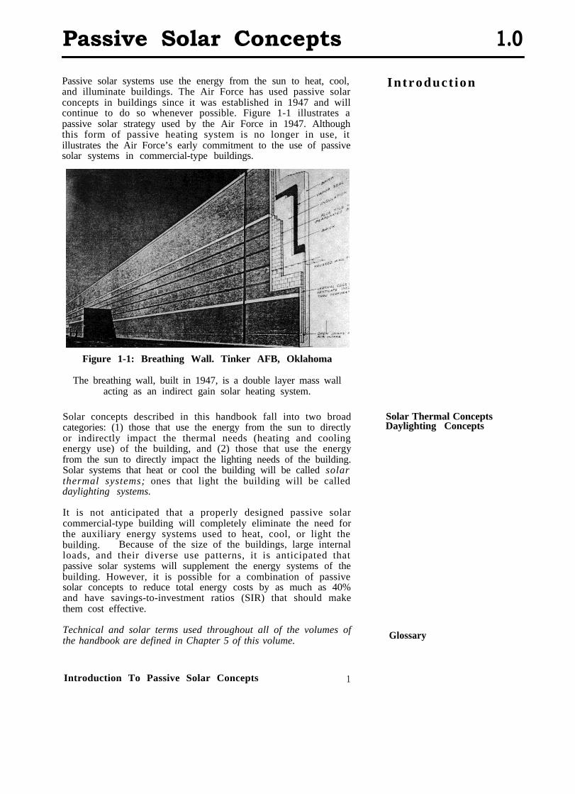
Passive solar systems use the energy from the sun to heat, cool, Introduct ionand illuminate buildings. The Air Force has used passive solarconcepts in buildings since it was established in 1947 and willcontinue to do so whenever possible. Figure 1-1 illustrates apassive solar strategy used by the Air Force in 1947. Althoughthis form of passive heating system is no longer in use, itillustrates the Air Force’s early commitment to the use of passivesolar systems in commercial-type buildings.
Figure 1-1: Breathing Wall. Tinker AFB, Oklahoma
The breathing wall, built in 1947, is a double layer mass wallacting as an indirect gain solar heating system.
Solar concepts described in this handbook fall into two broadcategories: (1) those that use the energy from the sun to directlyor indirectly impact the thermal needs (heating and coolingenergy use) of the building, and (2) those that use the energyfrom the sun to directly impact the lighting needs of the building.Solar systems that heat or cool the building will be called solarthermal systems; ones that light the building will be calleddaylighting systems.
Solar Thermal ConceptsDaylighting Concepts
It is not anticipated that a properly designed passive solarcommercial-type building will completely eliminate the need forthe auxiliary energy systems used to heat, cool, or light thebuilding. Because of the size of the buildings, large internalloads, and their diverse use patterns, it is anticipated thatpassive solar systems will supplement the energy systems of thebuilding. However, it is possible for a combination of passivesolar concepts to reduce total energy costs by as much as 40%and have savings-to-investment ratios (SIR) that should makethem cost effective.
Technical and solar terms used throughout all of the volumes ofthe handbook are defined in Chapter 5 of this volume. Glossary
Introduction To Passive Solar Concepts 1
1.0 Passive Solar Concepts
Solar Concepts
A total of eleven different passive concepts will be considered inthis handbook. Many other possible solar concepts wereevaluated. The ones listed below are appropriate in a widerange of climates and building types.
(H) Direct gain with storage(H) Indirect gain(H) Direct gain (without storage)(H) Sunspaces(C) Night Mechanical Ventilation(C) Natural Ventilation(L) Windows(L) Skylights(L) Sawtooth Apertures(L) Monitor Apertures(L) Atria
The letters (H), (C), and (L) stand for heating, cooling, andlighting, respectively, and are used to remind you of the purposefor each passive solar system concept.
Passive SolarS y s t e m
Components
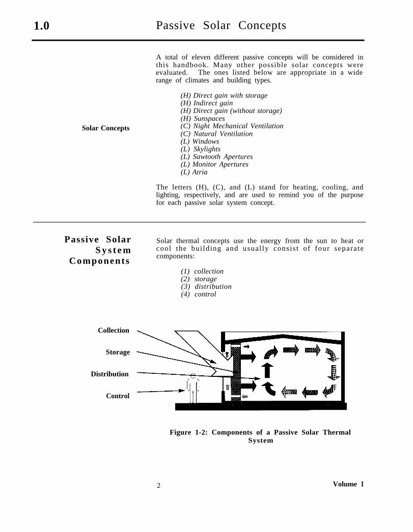
Solar thermal concepts use the energy from the sun to heat orcool the bui ld ing and usual ly consis t of four separa tecomponents:
(1) collection(2) storage(3) distribution(4) control
Collection
Storage
Distribution
Control
Figure 1-2: Components of a Passive Solar ThermalSystem
2 Volume I
Passive Solar Concepts 1.0
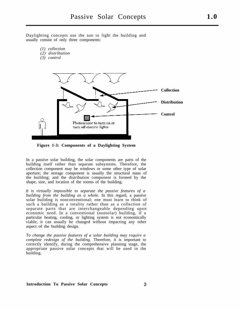
Daylighting concepts use the sun to light the building andusually consist of only three components:
(1) collection(2) distribution(3) control
Collection
Distribution
Control
Figure 1-3: Components of a Daylighting System
In a passive solar building, the solar components are parts of thebuilding itself rather than separate subsystems. Therefore, thecollection component may be windows or some other type of solaraperture; the storage component is usually the structural mass ofthe building; and the distribution component is formed by theshape, size, and location of the rooms of the building.
It is virtually impossible to separate the passive features of abuilding from the building as a whole. In this regard, a passivesolar building is nonconventional; one must learn to think ofsuch a building as a totality rather than as a collection ofseparate parts that are interchangeable depending uponeconomic need. In a conventional (nonsolar) building, if aparticular heating, cooling, or lighting system is not economicallyviable, it can usually be changed without impacting any otheraspect of the building design.
To change the passive features of a solar building may require acomplete redesign of the building. Therefore, it is important tocorrectly identify, during the comprehensive planning stage, theappropriate passive solar concepts that will be used in thebuilding.
Introduction To Passive Solar Concepts
1.0 Passive Solar Concepts
Passive Heating
Collection
Passive heating concepts use heat from the sun to offset winterheating needs. The collection subsystem may include windows,skylights, or some other type of solar aperture. The purpose ofthe collection subsystem is to allow sunlight into the building toheat the space and, if appropriate, to heat the storage mass. Thestorage subsystem usually includes parts of the floor or interiorwalls of the building.
Storage The purpose of the storage subsystem is to store the collected solarheat until it is needed by the occupants in the building. In mostcases, heat is collected during the daytime and used at night.Stored energy is released from the storage mass and distributedthroughout the building to offset heating energy use.
Distribution Distribution is accomplished by arranging the functional spacesof the building such that those that need heat are closest to thestorage subsystem.
The size and shape of the solar apertures (collection subsystem)affects the quantity of heating energy available to offset auxiliaryheating energy needs. The size of the storage subsystem affectsthe quantity of heat stored and the time delay between initialcollection and final use of energy. The size, shape, and location ofrooms in the building impact the optimum distribution of theheat throughout the building.
Heat distribution is accomplished by a combination of radiationand convection. Heat is radiated from the storage subsysteminto the rooms being heated after the collected solar energy haspassed through the storage system. Heat is convected throughthe air, warming it, and thereby warming the people in the room.
Control Control of the passive heating system might be quite differentfrom control of an HV or HVAC system. In many passivebuildings, control is achieved through the use of shading devices,or some other means to regulate the sunlight entering thebuilding. More complex passive buildings may also havethermostats to control fans and motors that regulate the air flowor control vents. In many passive buildings, the controlmechanisms are manual; that is, people control the building.
A balance between the size, shape, and location of each subsystemmust be achieved to ensure optimal system performance andefficiency. If the collection subsystem is too large or too small,then either too much energy is collected and the building isoverheated or not enough energy is collected to be effective.Similarly, if the storage subsystem is improperly sized, then iteither holds the energy in storage too long (oversized) or not longenough (undersized) to provide heat to the building when it isneeded. Finally, if the spaces of the building are not correctlyorganized, the heat cannot be distributed in a manner thatensures optimal auxiliary heating energy savings and comfort. Indeveloping this handbook, extensive analysis was done todetermine the -optimal size of different subsystems for variousclimate zones and building types.
4 Volume I
Passive Solar Concepts 1.0
When developing a knowledge of the optimal performancecharacteristics of a passive heating system, it is usually thestorage component that is least understood. When a storagesurface is illuminated by sunlight, the energy enters the massand is stored as heat. The type of material used, its thermalstorage capacity, thermal conductance, thickness, and the room’stemperature dictate the quantity of energy stored and the lengthof time it stays in storage. For example, a 4-inch concrete wallmight store energy for 4 hours before completely releasing it asheat. Similarly, 24 inches of concrete might store energy for 18 to20 hours before completely releasing it. By varying the type ofbuilding material used, and its thickness, it is possible tosubstantially vary the performance characteristics of a passiveheating system. The most commonly used materials in storagesystems are concrete and masonry products.
Passive heating systems that collect and distribute the heat in 4hours or less are called prompt systems. Ones that perform thisprocess and take more than 12 hours to release the heat arecalled extended systems. Most passive solar heating systems aredesigned to release their heat between 4 and 12 hours. This isespecially true of passive heating systems used in commercial-type buildings, such as administration buildings, which are notoccupied for more than 10 to 12 hours a day.
Prompt Systems
Extended Systems
Passive solar heating systems are often categorized by therelationship between the solar system and the building, that is,whether or not the solar system is part of a room being heated,part of the building, or totally separate from the building. Usingthis reasoning, there are three categories of passive solar heatingsystems:
(1) direct gain systems(2) indirect gain systems(3) isolated gain systems
This terminology will be used to describe the four passive heatingconcepts described in this handbook:
o Direct gain (without storage) (DG)o Direct gain plus storage (D+S)o Indirect gain (with storage)(IND)o Sunspace (isolated gain with storage) (SUN)
There are two types of direct gain heating systems. A directgain without storage, abbreviated DG, is a prompt system thatdoes not include any additional interior mass in the building(other than what would normally be available in structuralmembers, walls, ceilings, and floors). A direct gain system isschematically illustrated in Figure 1-4. Figure 1-5 contains aphotograph of a direct gain system used in an airport facility.Both of these figures are on the following page. A direct gainplus storage, abbreviated D+S, includes additional internal massto extend the storage capacity to approximately 8 hours. Thissystem is schematically illustrated in Figure 1-6, and aphotograph of one is shown in Figure l-7. Both figures are onpage 7.
Direct Gain (DG)
Direct Gain plus Storage(D+S)
Introduction To Passive Solar Concepts 5

1.0 Passive Solar Concepts
Figure 1-4: Direct Gain (DG) Schematic
Figure 1-5: Direct Gain. Walker Field Terminal,Grand Junction, Colorado
The roof apertures are used to provide both heating anddaylighting. They were primarily designed to be a
direct gain heating system.
6 Volume I
Passive Solar Concepts 1.0
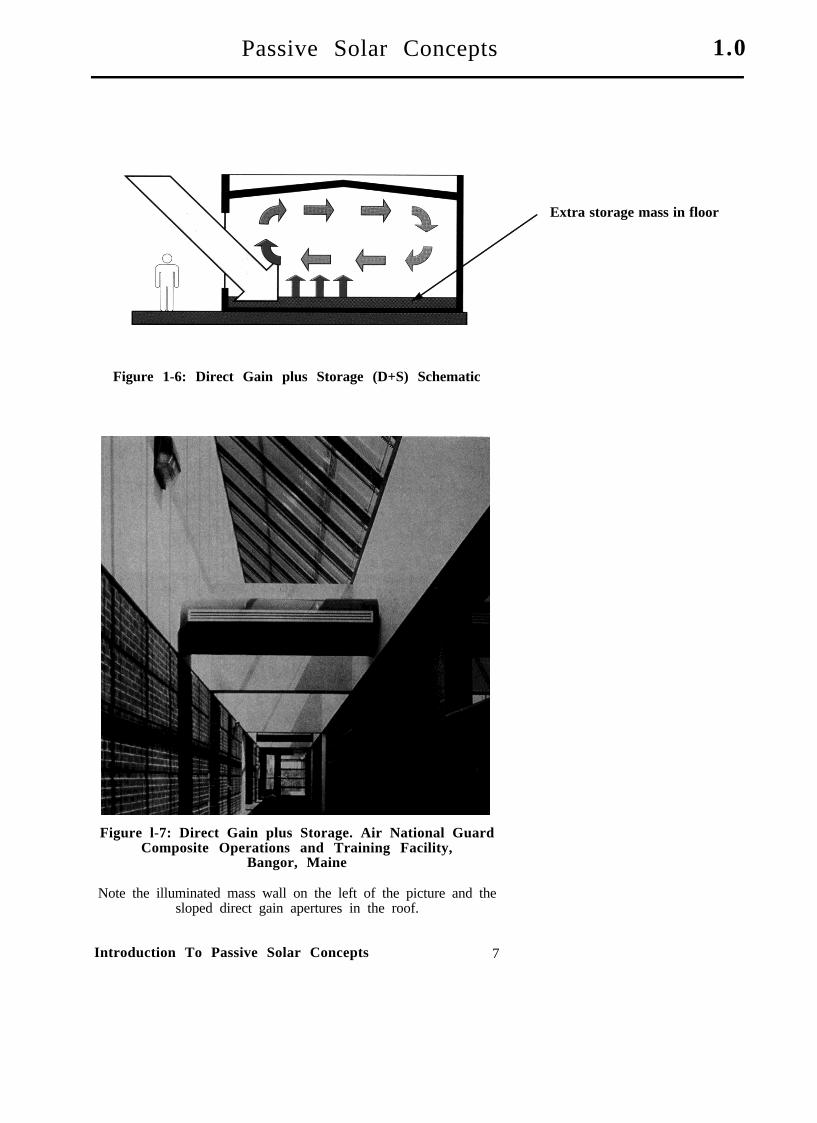
Extra storage mass in floor
Figure 1-6: Direct Gain plus Storage (D+S) Schematic
Figure l-7: Direct Gain plus Storage. Air National GuardComposite Operations and Training Facility,
Bangor, Maine
Note the illuminated mass wall on the left of the picture and thesloped direct gain apertures in the roof.
Introduction To Passive Solar Concepts 7
1.0 Passive Solar Concepts
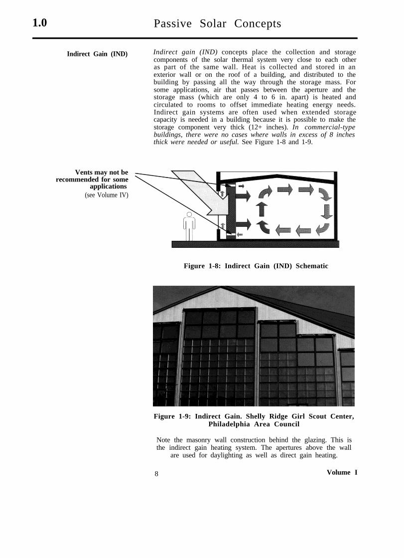
Indirect Gain (IND) Indirect gain (IND) concepts place the collection and storagecomponents of the solar thermal system very close to each otheras part of the same wall. Heat is collected and stored in anexterior wall or on the roof of a building, and distributed to thebuilding by passing all the way through the storage mass. Forsome applications, air that passes between the aperture and thestorage mass (which are only 4 to 6 in. apart) is heated andcirculated to rooms to offset immediate heating energy needs.Indirect gain systems are often used when extended storagecapacity is needed in a building because it is possible to make thestorage component very thick (12+ inches). In commercial-typebuildings, there were no cases where walls in excess of 8 inchesthick were needed or useful. See Figure 1-8 and 1-9.
Vents may not berecommended for some
applications(see Volume IV)
Figure 1-8: Indirect Gain (IND) Schematic
Figure 1-9: Indirect Gain. Shelly Ridge Girl Scout Center,Philadelphia Area Council
Note the masonry wall construction behind the glazing. This isthe indirect gain heating system. The apertures above the wall
are used for daylighting as well as direct gain heating.
8 Volume I
Passive Solar Concepts 1.0
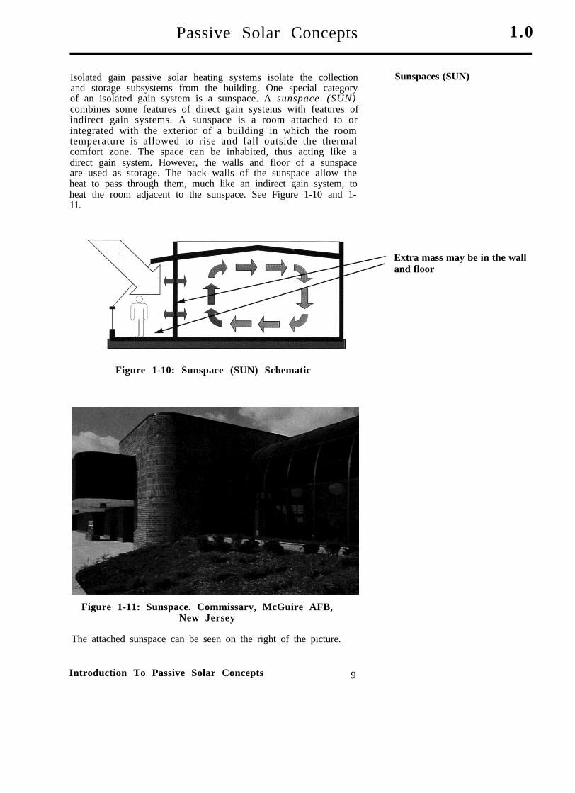
Isolated gain passive solar heating systems isolate the collectionand storage subsystems from the building. One special categoryof an isolated gain system is a sunspace. A sunspace (SUN)combines some features of direct gain systems with features ofindirect gain systems. A sunspace is a room attached to orintegrated with the exterior of a building in which the roomtemperature is allowed to rise and fall outside the thermalcomfort zone. The space can be inhabited, thus acting like adirect gain system. However, the walls and floor of a sunspaceare used as storage. The back walls of the sunspace allow theheat to pass through them, much like an indirect gain system, toheat the room adjacent to the sunspace. See Figure 1-10 and 1-11.
Sunspaces (SUN)
Extra mass may be in the walland floor
Figure 1-10: Sunspace (SUN) Schematic
Figure 1-11: Sunspace. Commissary, McGuire AFB,New Jersey
The attached sunspace can be seen on the right of the picture.
Introduction To Passive Solar Concepts 9

1 . 0 Passive Solar Concepts
Different types of passive heating systems have been consideredto allow for design variation and to recognize the fact that someconcepts work better in some building types. In general, passiveheating systems work best in buildings: (1) with low levels ofcontinuous internal load (less than 1.5 w/sf), (2) that areoccupied for extended periods (more than 8 hours), and (3) arelocated in climates with heating seasons in excess of 1,000 HDD.The severity and length of the heating season are not as criticalas the internal load and occupancy schedule of the building.
Passive Cool ing Passive cooling systems have the same basic components aspassive heating systems, but work in a different manner.Whereas the purpose of passive heating systems is to draw heatinto the building, the purpose of a passive cooling strategy is toremove or reject heat from the building, and thereby cool it.Because the mechanisms that drive passive cooling strategies arenot fully understood, many cooling concepts are difficult to fullyevaluate during the comprehensive planning process. Therefore,the number of cooling concepts advocated in this volume of thehandbook is limited. A more detailed discussion of passivecooling concepts can be found in Volume IV: Passive SolarDesign.
Peak Cooling Passive cooling benefits are achieved by avoidance of the coolingload in the building. In many commercial-type buildings, thepeak cooling requirement is directly associated with solar gains.By avoiding solar gains, a portion of the cooling load is avoided.This can be accomplished by shading the apertures of thebuilding.
Shading Shading can be achieved using the shape and form of the facade,using low transmission glazing, or using devices inside of thebuilding. From a passive solar viewpoint, the most effectivemethod of shading is on the outside of the building using
Figure 1-12: Shading Schematic
10 Volume I
Passive Solar Concepts 1.0
overhangs, fins, or louvers, as illustrated in Figures 1-12 and 1-13. A less effective method is to use glazing with a low shadingcoefficient.
Shading devices must be carefully designed. For passive heatingsystems, shading devices should block the sun during thesummer months hut allow sunlight to enter the building duringwinter. For daylighting systems, the sun is usually blockedduring the swing seasons (spring and autumn) as well as thesummer. In either case, there will be variations depending uponthe building type and internal loads.
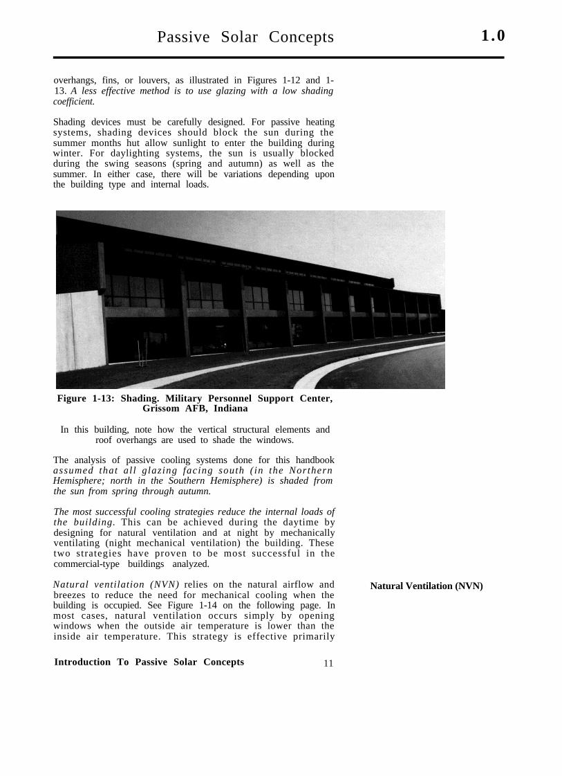
Figure 1-13: Shading. Military Personnel Support Center,Grissom AFB, Indiana
In this building, note how the vertical structural elements androof overhangs are used to shade the windows.
The analysis of passive cooling systems done for this handbookassumed that al l glazing facing south ( in the NorthernHemisphere; north in the Southern Hemisphere) is shaded fromthe sun from spring through autumn.
The most successful cooling strategies reduce the internal loads ofthe building. This can be achieved during the daytime bydesigning for natural ventilation and at night by mechanicallyventilating (night mechanical ventilation) the building. Thesetwo strategies have proven to be most successful in thecommercial-type buildings analyzed.
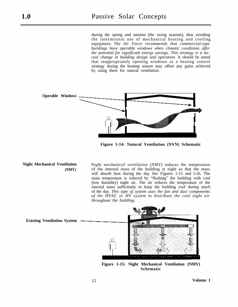
Natural ventilation (NVN) relies on the natural airflow and Natural Ventilation (NVN)breezes to reduce the need for mechanical cooling when thebuilding is occupied. See Figure 1-14 on the following page. Inmost cases, natural ventilation occurs simply by openingwindows when the outside air temperature is lower than theinside air temperature. This strategy is effective primarily
Introduction To Passive Solar Concepts 11
1.0 Passive Solar Concepts
during the spring and autumn (the swing seasons), thus avoidingthe intermit tent use of mechanical heat ing and cool ingequipment. The Air Force recommends that commercial-typebuildings have operable windows when climatic conditions offerthe potential for significant energy savings. This strategy is a no-cost change in building design and operation. It should be notedthat inappropriately opening windows as a heating controlstrategy during the heating season may offset any gains achievedby using them for natural ventilation.
Operable Windows
Figure 1-14: Natural Ventilation (NVN) Schematic
Night Mechanical Ventilation(NMV)
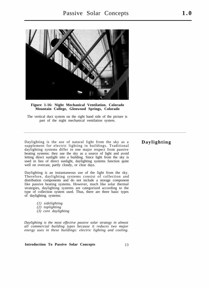
Night mechanical ventilation (NMV) reduces the temperatureof the internal mass of the building at night so that the masswill absorb heat during the day See Figures 1-15 and l-16. Themass temperature is reduced by “flushing” the building with cool(low humidity) night air. The air reduces the temperature of theinternal mass sufficiently to keep the building cool during muchof the day. This type of system uses the fan and duct componentsof the HVAC or HV system to distribute the cool night airthroughout the building.
Existing Ventilation System
Figure 1-15: Night Mechanical Ventilation (NMV)Schematic
12 Volume I
Passive Solar Concepts 1 . 0
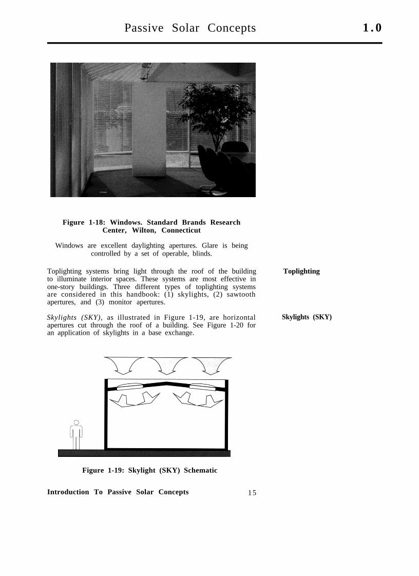
Figure 1-16: Night Mechanical Ventilation. ColoradoMountain College, Glenwood Springs, Colorado
The vertical duct system on the right hand side of the picture ispart of the night mechanical ventilation system.
Daylighting is the use of natural light from the sky as asupplement for electric lighting in buildings. Traditionaldaylighting systems differ in one major respect from passiveheating systems: they use the sky as a source of light and avoidletting direct sunlight into a building. Since light from the sky isused in lieu of direct sunlight, daylighting systems function quitewell on overcast, partly cloudy, or clear days.
Dayl ight ing
Daylighting is an instantaneous use of the light from the sky.Therefore, daylighting systems consist of collection anddistribution components and do not include a storage componentlike passive heating systems. However, much like solar thermalstrategies, daylighting systems are categorized according to thetype of collection system used. Thus, there are three basic typesof daylighting systems:
(1) sidelighting(2) toplighting(3) core daylighting
Daylighting is the most effective passive solar strategy in almostall commercial building types because it reduces two majorenergy uses in these buildings: electric lighting and cooling.
Introduction To Passive Solar Concepts 13

1.0 Passive Solar Concepts
Obviously, if daylighting is being used, the electric lighting mustbe turned off. This reduces electricity consumption for lighting.In many large buildings, the largest single component of thecooling load is the energy needed to remove heat generated bythe electric lighting system. Therefore, turning off the electriclighting, reduces, by as much as 40%, the energy used tomechanically cool the building.
A total of five different daylighting systems were analyzed forthis handbook. These were:
o Windows (sidelighting) (WIN)o Skylights (toplighting) (SKY)o Sawtooth apertures (toplighting) (SAW)o Monitor apertures (toplighting) (MON)o Atria (core daylighting) (ATR)
Windows (WIN) In this volume of the handbook, sidelighting systems are limitedto windows (WIN) to illuminate the interior of a building. SeeFigures 1-17 and 1-18. Additional sidelighting concepts arediscussed in Volume IV Passive Solar Design.
It is not necessary to add extensive amounts of glazing tosidelight a building. However, there are limitations to the depththat daylight can penetrate into a building from a window. I nmost cases, 30 feet is the maximum depth of daylight penetrationfor a typical office, though a greater depth can be assumed fortall hangars, depending on their geometry. The layout of interiorwalls and furnishings can reduce this depth of daylightpenetration. Beyond this distance, either toplighting or coredaylighting systems must be used.
Figure 1-17: Window (WIN) Schematic
14 Volume I
Passive Solar Concepts 1 . 0
Figure 1-18: Windows. Standard Brands ResearchCenter, Wilton, Connecticut
Windows are excellent daylighting apertures. Glare is beingcontrolled by a set of operable, blinds.
Toplighting systems bring light through the roof of the buildingto illuminate interior spaces. These systems are most effective inone-story buildings. Three different types of toplighting systemsare considered in this handbook: (1) skylights, (2) sawtoothapertures, and (3) monitor apertures.
Toplighting
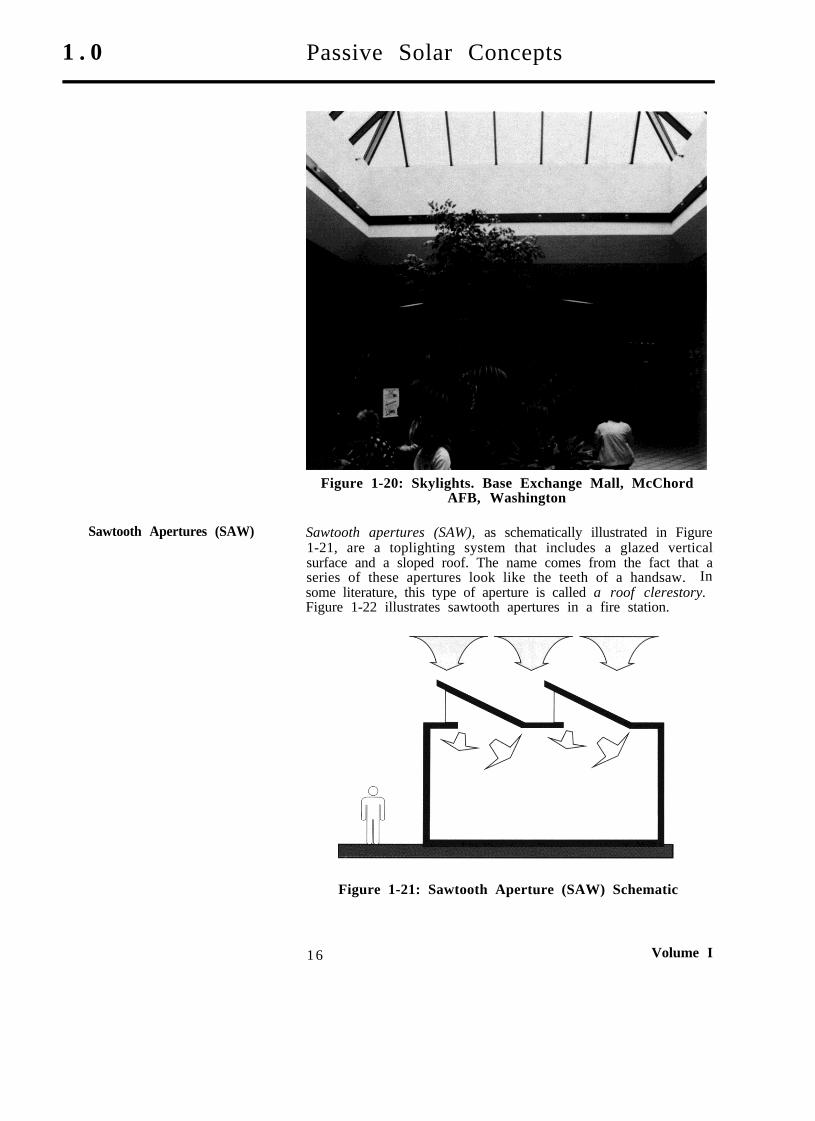
Skylights (SKY), as illustrated in Figure 1-19, are horizontalapertures cut through the roof of a building. See Figure 1-20 foran application of skylights in a base exchange.
Skylights (SKY)
Figure 1-19: Skylight (SKY) Schematic
Introduction To Passive Solar Concepts 15
1 . 0 Passive Solar Concepts
Figure 1-20: Skylights. Base Exchange Mall, McChordAFB, Washington
Sawtooth Apertures (SAW) Sawtooth apertures (SAW), as schematically illustrated in Figure1-21, are a toplighting system that includes a glazed verticalsurface and a sloped roof. The name comes from the fact that aseries of these apertures look like the teeth of a handsaw. Insome literature, this type of aperture is called a roof clerestory.Figure 1-22 illustrates sawtooth apertures in a fire station.
Figure 1-21: Sawtooth Aperture (SAW) Schematic
16 Volume I
Passive Solar Concepts 1.0
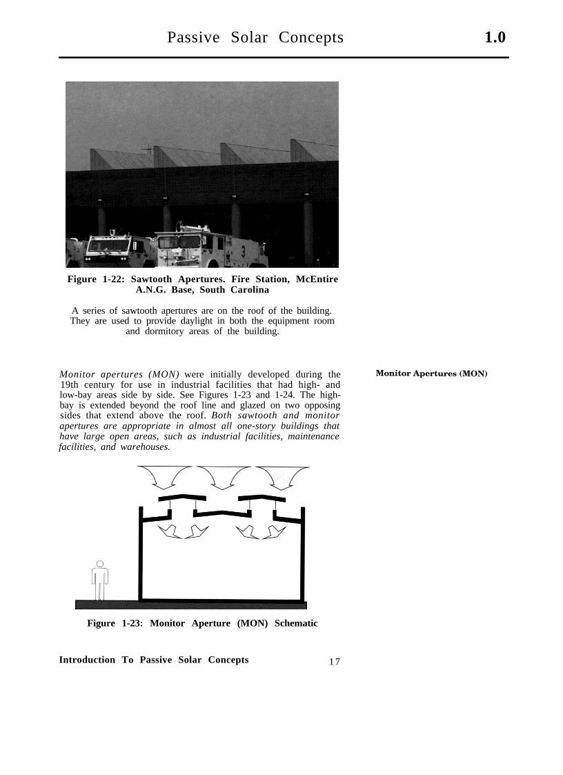
Figure 1-22: Sawtooth Apertures. Fire Station, McEntireA.N.G. Base, South Carolina
A series of sawtooth apertures are on the roof of the building.They are used to provide daylight in both the equipment room
and dormitory areas of the building.
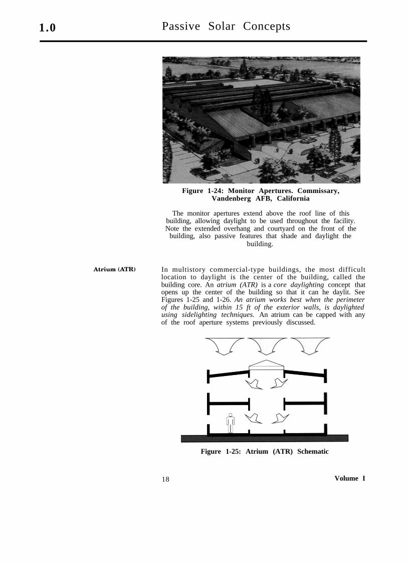
Monitor apertures (MON) were initially developed during the19th century for use in industrial facilities that had high- andlow-bay areas side by side. See Figures 1-23 and 1-24. The high-bay is extended beyond the roof line and glazed on two opposingsides that extend above the roof. Both sawtooth and monitorapertures are appropriate in almost all one-story buildings thathave large open areas, such as industrial facilities, maintenancefacilities, and warehouses.
Figure 1-23: Monitor Aperture (MON) Schematic
Introduction To Passive Solar Concepts 17
1.0 Passive Solar Concepts
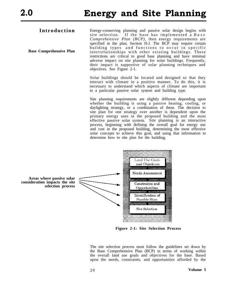
Figure 1-24: Monitor Apertures. Commissary,Vandenberg AFB, California
The monitor apertures extend above the roof line of thisbuilding, allowing daylight to be used throughout the facility.Note the extended overhang and courtyard on the front of the
building, also passive features that shade and daylight thebuilding.
In multistory commercial-type buildings, the most difficultlocation to daylight is the center of the building, called thebuilding core. An atrium (ATR) is a core daylighting concept thatopens up the center of the building so that it can he daylit. SeeFigures 1-25 and 1-26. An atrium works best when the perimeterof the building, within 15 ft of the exterior walls, is daylightedusing sidelighting techniques. An atrium can be capped with anyof the roof aperture systems previously discussed.
Figure 1-25: Atrium (ATR) Schematic
18 Volume I

Passive Solar Concepts 1.0
Figure 1-26: Atrium. Personnel Services Building, RobinsAFB, Georgia
The center bays of this building have been raised above the roofline to create a large atrium that allows daylight to he used to
offset electric lighting usage.
To save energy by using daylight, the electric lighting must beturned off when daylight can be used. This is accomplished byan automated electric lighting control system. Different controlstrategies are discussed in more detail in Volume IV: PassiveSolar Design.
Automated Electric LightingControl
If automated electric lighting control is not planned for aparticular building, it is not appropriate to assume that energysavings will result from daylighting the building.
A large number of passive solar concepts can be applied tocommercial-type buildings. The ones presented in this chapterare appropriate for most cases. However, other passive solarsystems may be appropriate under special circumstances, forparticular building types, or for a particular climate region.During the comprehensive planning process, it may he enough toknow that pass ive solar heat ing and/or cool ing, and/ordaylighting, are appropriate in a building. When more detailedanalysis is needed during the design process, it can be donefollowing the procedures found in Volume IV: Passive SolarDesign.
Conclus ions
For those interested in learning more about passive solar Additional Readingsystems, additional reading material is listed in Chapter 4.
Introduction To Passive Solar Concepts 19
2.0 Energy and Site Planning
Introduct ion
Base Comprehensive Plan
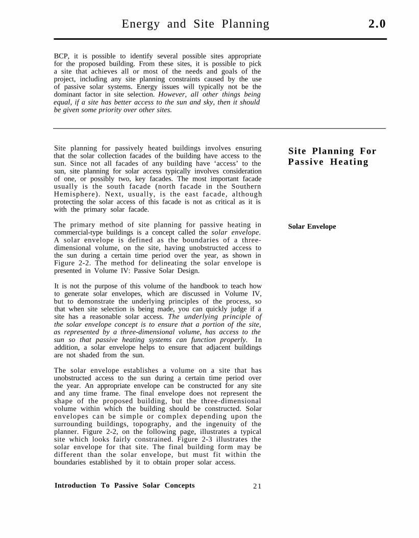
Energy-conserving planning and passive solar design begins withs i te se lect ion. I f t h e b a s e h a s i m p l e m e n t e d a B a s eComprehensive Plan (BCP), then energy requirements arespecified in the plan, Section II-J. The BCP may require certainbu i l d ing t ypes a n d f u n c t i o n s t o o c c u r i n s p e c i f i cin ter re la t ionships wi th o ther exis t ing bui ld ings . Theserestrictions are critical to good base planning and have minimaladverse impact on site planning for solar buildings. Frequently,their impact is supportive of solar planning techniques andobjectives. See Figure 2-1.
Solar buildings should be located and designed so that theyinteract with climate in a positive manner. To do this, it isnecessary to understand which aspects of climate are importantto a particular passive solar system and building type.
Site planning requirements are slightly different depending uponwhether the building is using a passive heating, cooling, ordaylighting strategy, or a combination of these. The decision tosite plan for one strategy over another is dependent upon theprimary energy uses in the proposed building and the mosteffective passive solar system. Site planning is an interactiveprocess, beginning with defining the overall goal for energy useand cost in the proposed building, determining the most effectivesolar concepts to achieve this goal, and using that information todetermine how to site plan for the building.
Areas where passive solarconsideration impacts the site
selection process
Figure 2-1: Site Selection Process
The site selection process must follow the guidelines set down bythe Base Comprehensive Plan (BCP) in terms of working withinthe overall land use goals and objectives for the base. Basedupon the needs, constraints, and opportunities afforded by the
2 0 Volume I
Energy and Site Planning 2.0
BCP, it is possible to identify several possible sites appropriatefor the proposed building. From these sites, it is possible to picka site that achieves all or most of the needs and goals of theproject, including any site planning constraints caused by the useof passive solar systems. Energy issues will typically not be thedominant factor in site selection. However, all other things beingequal, if a site has better access to the sun and sky, then it shouldbe given some priority over other sites.
Site planning for passively heated buildings involves ensuringthat the solar collection facades of the building have access to thesun. Since not all facades of any building have ‘access’ to thesun, site planning for solar access typically involves considerationof one, or possibly two, key facades. The most important facadeusually is the south facade (north facade in the SouthernHemisphere). Next, usually, is the east facade, althoughprotecting the solar access of this facade is not as critical as it iswith the primary solar facade.
Site Planning ForPassive Heating
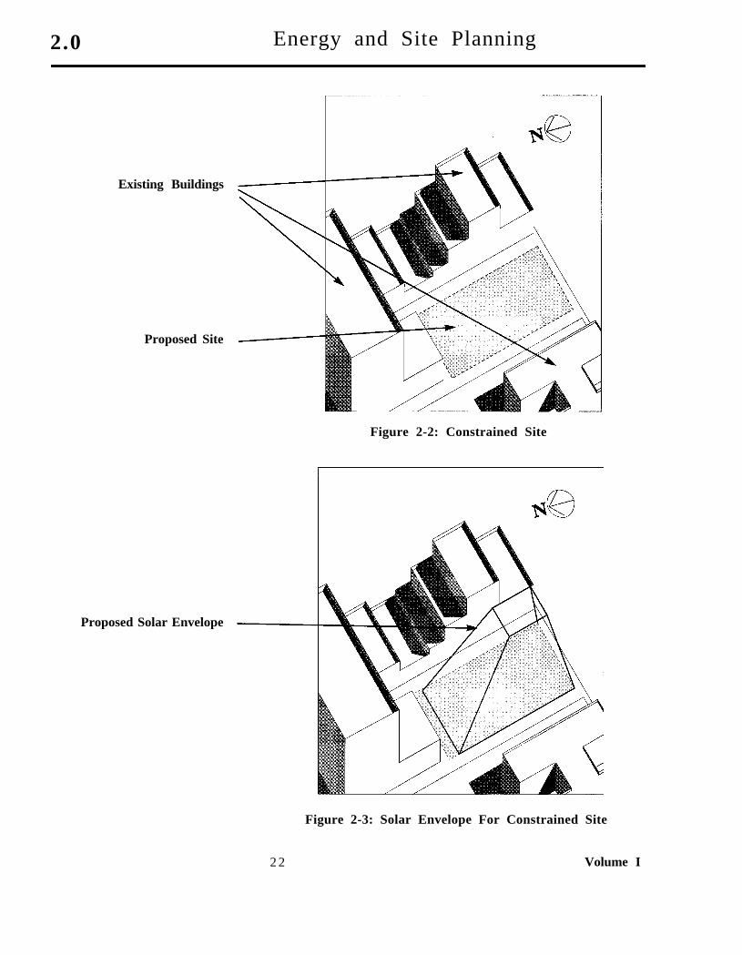
The primary method of site planning for passive heating incommercial-type buildings is a concept called the solar envelope.A solar envelope is defined as the boundaries of a three-dimensional volume, on the site, having unobstructed access tothe sun during a certain time period over the year, as shown inFigure 2-2. The method for delineating the solar envelope ispresented in Volume IV: Passive Solar Design.
Solar Envelope
It is not the purpose of this volume of the handbook to teach howto generate solar envelopes, which are discussed in Volume IV,but to demonstrate the underlying principles of the process, sothat when site selection is being made, you can quickly judge if asite has a reasonable solar access. The underlying principle ofthe solar envelope concept is to ensure that a portion of the site,as represented by a three-dimensional volume, has access to thesun so that passive heating systems can function properly. Inaddition, a solar envelope helps to ensure that adjacent buildingsare not shaded from the sun.
The solar envelope establishes a volume on a site that hasunobstructed access to the sun during a certain time period overthe year. An appropriate envelope can be constructed for any siteand any time frame. The final envelope does not represent theshape of the proposed building, but the three-dimensionalvolume within which the building should be constructed. Solarenvelopes can be simple or complex depending upon thesurrounding buildings, topography, and the ingenuity of theplanner. Figure 2-2, on the following page, illustrates a typicalsite which looks fairly constrained. Figure 2-3 illustrates thesolar envelope for that site. The final building form may bedifferent than the solar envelope, but must fit within theboundaries established by it to obtain proper solar access.
Introduction To Passive Solar Concepts 21
2.0 Energy and Site Planning
Existing Buildings
Proposed Site
Figure 2-2: Constrained Site
Proposed Solar Envelope
Figure 2-3: Solar Envelope For Constrained Site
2 2 Volume I
Energy and Site Planning 2.0
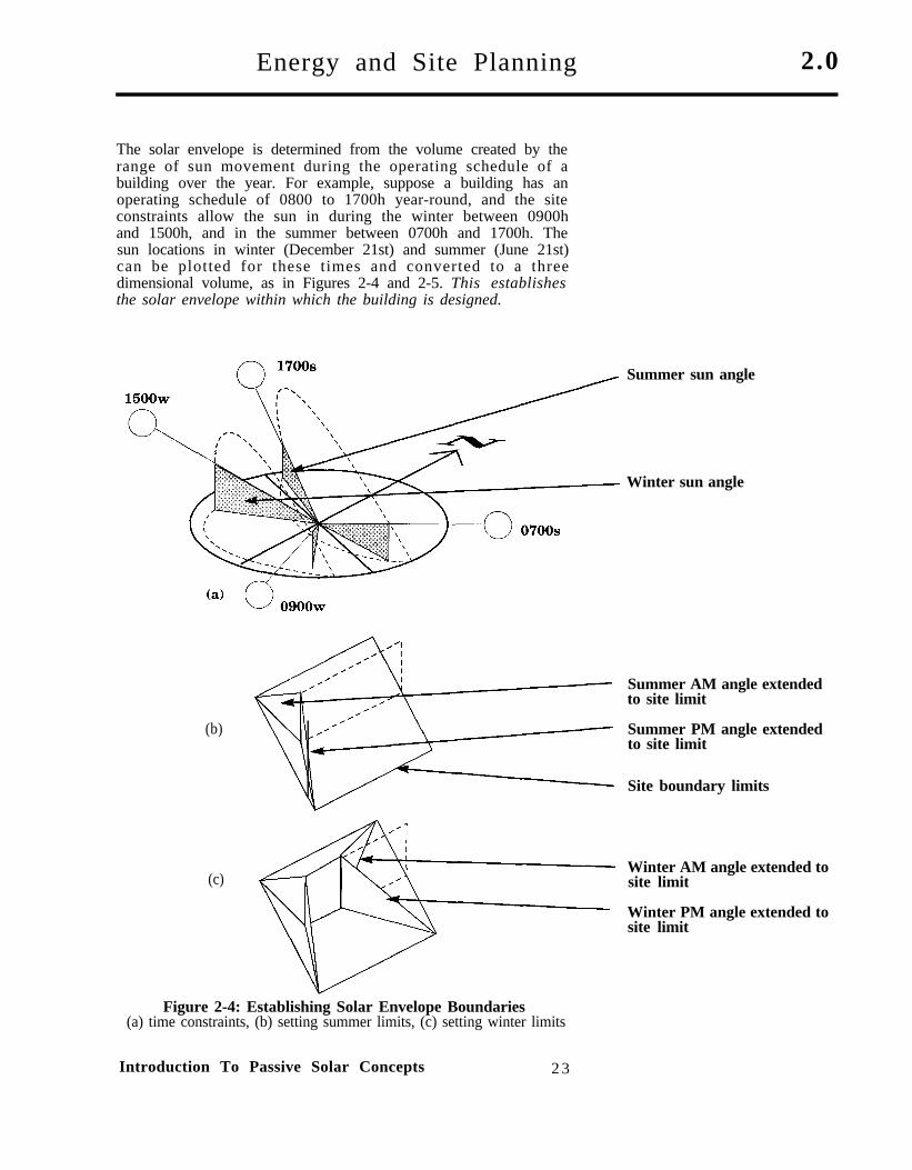
The solar envelope is determined from the volume created by therange of sun movement during the operating schedule of abuilding over the year. For example, suppose a building has anoperating schedule of 0800 to 1700h year-round, and the siteconstraints allow the sun in during the winter between 0900hand 1500h, and in the summer between 0700h and 1700h. Thesun locations in winter (December 21st) and summer (June 21st)can be plotted for these times and converted to a threedimensional volume, as in Figures 2-4 and 2-5. This establishesthe solar envelope within which the building is designed.
(b)
(c)
Figure 2-4: Establishing Solar Envelope Boundaries(a) time constraints, (b) setting summer limits, (c) setting winter limits
Summer sun angle
Winter sun angle
Summer AM angle extendedto site limit
Summer PM angle extendedto site limit
Site boundary limits
Winter AM angle extended tosite limit
Winter PM angle extended tosite limit
Introduction To Passive Solar Concepts 2 3
2 . 0 Energy and Site Planning
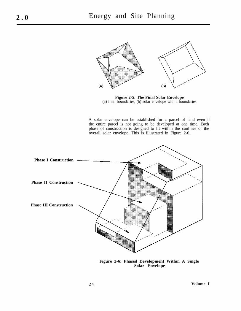
Figure 2-5: The Final Solar Envelope(a) final boundaries, (b) solar envelope within boundaries
A solar envelope can be established for a parcel of land even ifthe entire parcel is not going to be developed at one time. Eachphase of construction is designed to fit within the confines of theoverall solar envelope. This is illustrated in Figure 2-6.
Phase I Construction
Phase II Construction
Phase III Construction
Figure 2-6: Phased Development Within A SingleSolar Envelope
2 4 Volume I
Energy and Site Planning 2 . 0
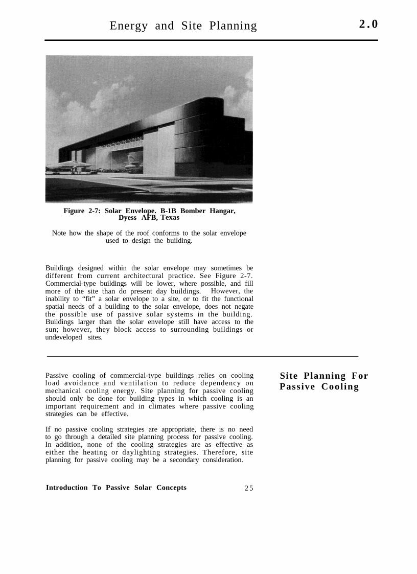
Figure 2-7: Solar Envelope. B-1B Bomber Hangar,Dyess AFB, Texas
Note how the shape of the roof conforms to the solar envelopeused to design the building.
Buildings designed within the solar envelope may sometimes bedifferent from current architectural practice. See Figure 2-7.Commercial-type buildings will be lower, where possible, and fillmore of the site than do present day buildings. However, theinability to “fit” a solar envelope to a site, or to fit the functionalspatial needs of a building to the solar envelope, does not negatethe possible use of passive solar systems in the building.Buildings larger than the solar envelope still have access to thesun; however, they block access to surrounding buildings orundeveloped sites.
Passive cooling of commercial-type buildings relies on coolingload avoidance and ventilation to reduce dependency onmechanical cooling energy. Site planning for passive coolingshould only be done for building types in which cooling is animportant requirement and in climates where passive coolingstrategies can be effective.
Site Planning ForPassive Cool ing
If no passive cooling strategies are appropriate, there is no needto go through a detailed site planning process for passive cooling.In addition, none of the cooling strategies are as effective aseither the heating or daylighting strategies. Therefore, siteplanning for passive cooling may be a secondary consideration.
Introduction To Passive Solar Concepts 2 5
2.0 Energy and Site Planning
The most important factors to be considered when planning for apassive cooling system are:
(1) high humidity (60%+) levels(2) air movement over and through the site(3) solar gains through glazing
Solar gains (through glazing) and air movement can be handledthrough a combination of site planning and building design.High humidity (60% +) levels during occupied hours are a givenin many locations that ma.y limit the effective use of passivecooling.
High Humidity Humidity is a critical consideration for two reasons. First, highhumidity levels can create physical discomfort even if the airtemperature is comfortable. One of the purposes of mechanicalcooling systems is to maintain a reasonable humidity level insidea building so that it is a comfortable work environment. Thesecond reason that humidity is a critical design element has to dowith the energy needed by a mechanical cooling system to removehumidity and moisture from a building. In warm and humidclimates, opening a window for an hour may require a constant24 hours of mechanical cooling to remove the moisture from thebuilding that enters through the window and permeates thestructure. Obviously, trading off 1 hour of “free” natural coolingfor 24 hours of mechanical cooling is not cost effective.
Keep in mind that the site planning process and the buildingcomprehensive planning process are interactive. For a givenbuilding type in a given climate region, one may have alreadydetermined that all, some, or none of the recommended coolingstrategies are appropriate.
Air Movement Air movement, in the form of adequate ventilation, is perhaps themost important aspect of passive cooling. Air movement as lowas 2.3 miles per hour can reduce the effective air temperature ina building by as much as 5°F.
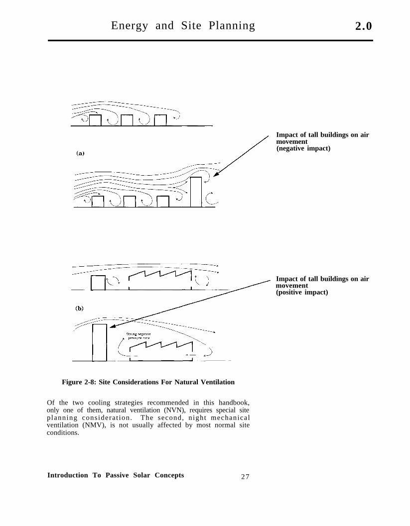
Site planning for natural ventilation requires knowledge of theprevailing wind directions and speeds, and being able todetermine what parts of a site are most favorable for ventilation.Rapid changes in slope, dense vegetation, and tall surroundingbuildings can effectively block the prevailing breezes, eventhough they may be useful to shade the sun from the building.See Figure 2-8 on the following page.
Solar Gains Solar gains represent an important part of the cooling load of alarge building. Reducing solar gains reduces energy use, peakdemand, and mechanical cooling equipment size. W h e nconsidering a site and trying to judge what the implications ofsite planning are on solar gains, you should be looking for treesand surrounding buildings that can shade the proposedbuilding.
2 6 Volume I
Energy and Site Planning 2.0
Figure 2-8: Site Considerations For Natural Ventilation
Of the two cooling strategies recommended in this handbook,only one of them, natural ventilation (NVN), requires special siteplanning considerat ion. The second, night mechanicalventilation (NMV), is not usually affected by most normal siteconditions.
Introduction To Passive Solar Concepts 27
Impact of tall buildings on airmovement(negative impact)
Impact of tall buildings on airmovement(positive impact)

2 . 0 Energy and Site Planning
Planning ForDayl ight ing
Site planning for daylighting is different from site planning forsolar thermal systems. Daylighting systems use the light from aclear or overcast sky to illuminate the interior of buildings. Inmost cases, direct sunlight is avoided. Therefore, it is notnecessary to protect a specific facade (such as the south or eastfacade) as in a passive thermal system. In general, any facadecan be used to daylight the interior of a building. When siteplanning for daylight, the following simple rules can be applied:
Protected Zones:A) Single Aperture
B) Entire WallDependent upon building height
or height of the surroundingbuildings.
Protect any two opposite facades of a building.
Protect any facade and the roof of the building.
Site planning to “protect” a facade of a building means to keep itfree of major obstructions, such as adjacent buildings and largetrees. For a daylighted building, this means a space adjacent tothe daylighted facade(s) equal to one-half of the building heightmust be left relatively free of obstructions to ensure that lightfrom the sky can reach the facade(s). This type of daylight accessrequirement is far less constraining than most requirements forpassive heating systems.
For example, if the north and south facades of a building arebeing used to daylight the building and the building is 40 feettall, then a space 20 feet wide must be left clear adjacent to thedaylighted facades of the building. See Figure 2-9. Similarly, ifthe site already has a building 60 feet tall, no new buildingsshould be built within 30 feet of it, assuming the new buildingsare less than 60 feet tall. All of the values used in these examplesrepresent minimum protection zones. Good design sense and thescale of the building will also help determine the size and shapeof the protected zone. Daylight planning tools are explained inmore detail in Volume IV: Passive Solar Design.
Figure 2-9: Site Planning For Daylighting
2 8 Volume I
Energy and Site Planning 2.0
No special protection or site planning is needed for toplightingand core daylighting concepts because they typically have anunobstructed view of the sky.
When looking at possible building sites and attempting todetermine whether a site is appropriate for a daylit building, it ishelpful to have some sense of the proposed building’s overall sizeand volume so that an estimate of the space needed to protect thedaylighting facades can be made. If the building is also going touse a passive heating system, the space surrounding the solarenvelope must be protected.
Most building sites are adjacent to streets or alleyways. Facadesfacing these are usually relatively easy to protect. Sites used forlow (one-story, low-bay) buildings that are surrounded by tallhigh-bay buildings should consider the use of toplightingconcepts, assuming these concepts are appropriate for thebuilding type and climate.
Daylighting is the most appropriate passive system for allbuilding types in all climate regions. Therefore, site planning fordaylighting will be a routine part of the comprehensive buildingplanning process. Fortunately, it is also the easiest system toaccommodate.
In general, passive solar buildings which take advantage of theclimate are less tolerant to changes in orientation and shape thanare climate rejecting buildings. However, sites do not have to beideal for passive solar strategies to be appropriate. This does notnegate the need for site planning; it just helps keep the siteplanning process, as applied to large passive solar commercial-type buildings, in its proper perspective. The impact of buildingorientation on site selection is discussed in more detail inVolume IV: Passive Solar Design.
B u i l d i n gOrientation andS h a p e
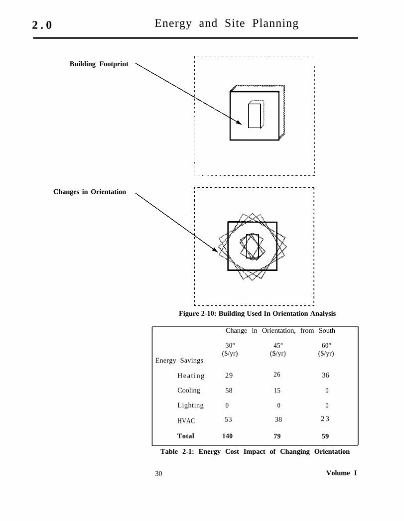
Internal loads (people, equipment, lighting, and so forth) have amajor impact upon the importance of orientation and shape insite planning. The importance of internal loads and their impacton site planning can best be illustrated by looking at severalexamples. The first is a large administration building located inthe northeastern United States. This example building is threestories tall with 10,000 sf of floor area per story. The annualenergy costs (1987) are $36,900 per year, or about $1.23 persquare foot per year. The building is oriented such that the fourfacades face north, south, east, and west. The building site planis illustrated in Figure 2-10 and energy costs are shown in Table2-l. Both of these are on the following page.
Introduction To Passive Solar Concepts 2 9
2 . 0 Energy and Site Planning
Building Footprint
Changes in Orientation
Figure 2-10: Building Used In Orientation Analysis
Change in Orientation, from South
Energy Savings
30° 45° 60°($/yr) ($/yr) ($/yr)
Heat ing 29 26 36
Cooling 58 15 0
Lighting 0 0 0
HVAC 53 38 2 3
Total 140 79 59
Table 2-1: Energy Cost Impact of Changing Orientation
30 Volume I
Energy and Site Planning 2.0
If the building is reoriented such that the primary facades arerotated 30°, 45°, and 60° east of due south, the greatest savingsoccur when the building is rotated 30°. This results in a $140 peryear savings, considerably less than one-half of 1% of the annualenergy costs. Rotating the building 45° or 60° results in evensmaller savings of $79.00 per year or $59.00 per year,respectively. Clearly, the orientation of this building has littleeffect on the energy consumption. It is not sensitive to climate,and its energy use is determined by internal loads.
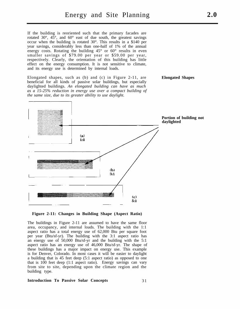
Elongated shapes, such as (b) and (c) in Figure 2-11, arebeneficial for all kinds of passive solar buildings, but especiallydaylighted buildings. An elongated building can have as muchas a 15-25% reduction in energy use over a compact building ofthe same size, due to its greater ability to use daylight.
Elongated Shapes
Figure 2-11: Changes in Building Shape (Aspect Ratio)
The buildings in Figure 2-11 are assumed to have the same floorarea, occupancy, and internal loads. The building with the 1:1aspect ratio has a total energy use of 62,000 Btu per square footper year (Btu/sf-yr). The building with the 3:1 aspect ratio hasan energy use of 50,000 Btu/sf-yr and the building with the 5:1aspect ratio has an energy use of 46,000 Btu/sf-yr. The shape ofthese buildings has a major impact on energy use. This exampleis for Denver, Colorado. In most cases it will be easier to daylighta building that is 45 feet deep (5:1 aspect ratio) as opposed to onethat is 100 feet deep (1:1 aspect ratio). Energy savings can varyfrom site to site, depending upon the climate region and thebuilding type.
Introduction To Passive Solar Concepts 31
Portion of building notdaylighted

3.0 Energy and Buildings
Introduct ion
< = less than> = greater than
Building-Type Code Used InThis Handbook
A. ADMIN, <5000 SFB. ADMIN, >5000 SFC. ADMIN, MULTISTORYD. ADMIN, COMPUTER FACILITYE. DINING FACILITYF. DORMITORYG. FIRE STATIONH. INDUSTRIAL FACILITYI. MAINTENANCE, <5000 SFJ.K.L.M.N.O.P.
R.NC.
MAINTENANCE, HIGH-BAYMAINTENANCE, HVACMAINTENANCE, LOW-BAYTRAINING, AUDITORIUMTRAINING, <5000 SFTRAINING, >5000 SFTRAINING, MULTISTORYTRAINING, GYMNASIUMWAREHOUSENO CURRENT BUILDING TYPE
A total of 18 different commercial-type buildings were analyzedfor this handbook. A listing of these building types, in the orderthey appear in various charts and appendices throughout thehandbook, is as follows:
A. ADMIN, <5000 SFB. ADMIN, >5000 SFC. ADMIN, MULTISTORYD. ADMIN, COMPUTER FACILITYE. DINING FACILITYF. DORMITORYG. FIRE STATIONH. INDUSTRIAL FACILITYI. MAINTENANCE, <5000 SFJ. MAINTENANCE, HIGH-BAYK. MAINTENANCE, AIR CONDITIONEDL. MAINTENANCE, LOW -BAYM. TRAINING, AUDITORIUMN. TRAINING, <5000 SFO. TRAINING, >5000 SFP. TRAINING, MULTISTORYQ. TRAINING, GYMNASIUMR. WAREHOUSE
These building types represent general categories of commercial-type buildings and do not describe specific buildings as found inthe USAF building type category codes. For example, a lawoffice, building code 610-112, would be an administrativebuilding, but it could be <5000 sf, >5000 sf, or multistory.
Appendix B lists all of the USAF building-type category codesand the building type they represent. An example of Appendix Bis shown in Table 3-1.
Q .
Table 3-1: Appendix B: Building Type Category Codes
3 2 Volume I
Energy and Buildings 3.0
Climates are typically characterized as rainy, sunny, hot, cloudy,humid, cold, and so forth. However, subjective characterizationssuch as these are inadequate when concerned with buildingenergy performance because: (1) they may not be an indicator ofb u i l d i n g e n e r g y u s e , a n d ( 2 ) c o m p a r i n g s u b j e c t i v echaracterizations often leads to error. For example, the followingstatement would widely be considered true: “It rains more inSeattle than in Boston.” Two questions should be asked: (1) israinfall usually an indicator of building energy use?, and (2) doesit really rain more in Seattle than Boston? The answer to bothquestions is no.
Weather represents the momentary condition of the atmospherewith respect to temperature (hot or cold), moisture (wet or dry),wind (calm or storm), sky (clear or cloudy), and pressure (high orlow). Climate represents the average long-term condition of theatmosphere. Therefore, climate variables are often used tocategorize regions that have similar characteristics. In general,different climate variables are used to analyze the energy use of abuilding depending upon whether the building is residential ornonresidential.
The climate variables that usually influence commercial-typebuilding energy use are:
0 outside air temperature0 humidity0 solar radiation
Climate regions group different geographic locations according tospecific sets of climate variables. Climate regions that areindicators of building energy use commonly use heating degreedays (HDD) and cooling degree days (CDD) as a way to establishregional boundaries. These have previously been used by theAir Force to establish building climate regions and are discussedin Engineering Technical Letter (ETL): Energy Budget Figures.
Heating and cooling degree days are not sufficient to analyzecomplex commercial-type passive solar buildings for two basicreasons: (1) they do not encompass the latent cooling load (thatis, the moisture load) common in nonresidential buildings, causedby a high occupancy density, and (2) they do not include someform of solar (or daylighting) variable to properly analyze passivesolar commercial-type buildings.
To determine the energy use in this handbook, four climatevariables were used to establish climate regions:
(1)(2)(3)(4)
Heating Degree Days (HDD)Cooling Degree Days (CDD)Latent Enthalpy Hours (LEH)Cloudiness Index (RAD)
Introduction To Passive Solar Concepts 33
Climate andBuildings
Weather
Climate
Climate Regions
Engineering Technical Letter(ETL): Energy Budget Figures
Climate Variables Used toEstablish Climate Regions

3.0 Energy and Buildings
Heating Degree Days (HDD) The number of Heating Degree Days (HDD) in a single day isdetermined by subtracting the average (maximum - minimum)temperature for that day from a reference temperature: 65°F inthe United States and 60°F in the United Kingdom. The averagetemperature must be less than 65°F for heating degree days tooccur. Heating is assumed to be required under these conditions.For days when the average temperature is greater than 65°F, seethe discussion on Cooling Degree Days (CDD) beginning on thenext page.
The number of heating degree days for a month or year isdetermined by summing all of the daily values for a month oryear, respectively. Heating Degree Days (HDD) are considered agood indicator of heating energy use and are often used todetermine the total climate related heating energy use of abuilding located on a given air base or in a given climate region.Cold climates have HDD values for a year in excess of 6,000;extremely cold climates have HDD values greater than 10,000.Warm climates may have HDD values for a year less than 2,000,while tropical climates may have no heating degree days, that is,HDD equals 0. The range of HDD annual values for the freeworld is from 20,264 (Barrow, Alaska) to 0 (several locales,including such places as Honolulu and Wake Island).
AFM 88-29 Facility Designand Planning: Engineering
Weather Data
As you might suspect, a wide range of HDD values exists in acountry as large as the United States. For example, for air baseslocated near Fort Wayne, Indiana, Sacramento, California, orApalachicola, Florida, the HDDs would be 6208, 2842, and 1361,respectively. Each of these locales would have a different needfor heating and the appropriate passive solar system to meet apart of this need would therefore be quite different in concept andcapacity.
Fort Wayne, IN
Information about specific HDDs characteristics of any air basecan be found in AFM 88-29 (TM 5-784, NAVFAC P-89) Facility
Sacramento, CA
Apalachicola, FL
Figure 3-2: Heating Degree Day (HDD) Example
3 4 Volume I

Energy and Buildings 3.0
Cooling Degree Days (CDDs) are quite similar to HDDs exceptthey represent a cooling condition rather than a heatingcondition. Therefore, the number of Cooling Degree Days in as ingle day is determined by subtract ing the referencetemperature from the average temperature for the day. Since thisis a cooling condition, it is assumed that the average temperatureis greater than the reference temperature (65°F).
If an air conditioning system is used to cool a building, thenCDDs provide some information about the climate related coolingload. Since the CDD is an indicator of cooling needs, values arelow in cold climates, which have little cooling, and high inclimates which are warm. The range of CDD annual values forthe free world is from 0 (several locales, such as Barrow, Alaska)to 7576 in Khartoum in the Sudan. Fort Wayne, Sacramento,and Apalachicola have values of 747, 1157, and 2662,respectively.
Cooling Degree Days (HDD)
Information about specific CDDs characteristics of any air basecan be found in AFM 88-29 (TM 5-784, NAVFAC P-89) FacilityDesign and Planning: Engineering Weather Data.
Sacramento, CA
Fort Wayne, IN
Apalachicola, FL
Figure 3-3: Cooling Degree Day (CDD) Example
In commercial-type buildings, or even large residences such asdormitories or apartments, a great deal of energy is expendedremoving moisture from the building during the cooling season.This type of energy use is more important in large buildings thanin detached houses. To determine the impact of this type ofenergy use, called latent energy use, on buildings, a new climatemeasure has been developed called a Latent Enthalpy Hour(LEH).
Latent Enthalpy Hours (LEH)
Introduction To Passive Solar Concepts 35
3.0 Energy and Buildings
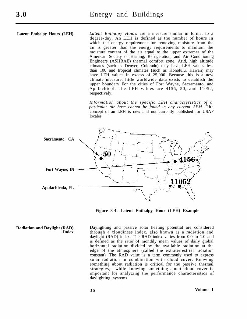
Latent Enthalpy Hours (LEH) Latent Enthalpy Hours are a measure similar in format to adegree-day. An LEH is defined as the number of hours inwhich the energy requirement for removing moisture from theair is greater than the energy requirements to maintain themoisture content of the air equal to the upper extremes of theAmerican Society of Heating, Refrigeration, and Air ConditioningEngineers (ASHRAE) thermal comfort zone. Arid, high altitudeclimates (such as Denver, Colorado) may have LEH values lessthan 100 and tropical climates (such as Honolulu, Hawaii) mayhave LEH values in excess of 25,000. Because this is a newclimate measure, little worldwide data exists to establish theupper boundary For the cities of Fort Wayne, Sacramento, andApalachicola the LEH values are 4156, 50, and 11052,respectively.
Information about the specific LEH characteristics of aparticular air base cannot be found in any current AFM. Theconcept of an LEH is new and not currently published for USAFlocales.
Sacramento, CA
Fort Wayne, IN
Apalachicola, FL
Radiation and Daylight (RAD)Index
Figure 3-4: Latent Enthalpy Hour (LEH) Example
Daylighting and passive solar heating potential are consideredthrough a cloudiness index, also known as a radiation anddaylight (RAD) index. The RAD index varies from 0.0 to 1.0 andis defined as the ratio of monthly mean values of daily globalhorizontal radiation divided by the available radiation at theedge of the atmosphere (called the extraterrestrial radiationconstant). The RAD value is a term commonly used to expresssolar radiation in combination with cloud cover. Knowingsomething about radiation is critical for the passive thermalstrategies, while knowing something about cloud cover isimportant for analyzing the performance characteristics ofdaylighting systems.
3 6 Volume I
Energy and Buildings 3.0
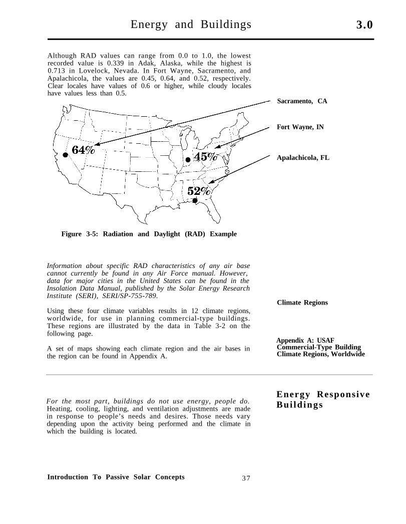
Although RAD values can range from 0.0 to 1.0, the lowestrecorded value is 0.339 in Adak, Alaska, while the highest is0.713 in Lovelock, Nevada. In Fort Wayne, Sacramento, andApalachicola, the values are 0.45, 0.64, and 0.52, respectively.Clear locales have values of 0.6 or higher, while cloudy localeshave values less than 0.5.
Sacramento, CA
Fort Wayne, IN
Apalachicola, FL
Figure 3-5: Radiation and Daylight (RAD) Example
Information about specific RAD characteristics of any air basecannot currently be found in any Air Force manual. However,data for major cities in the United States can be found in theInsolation Data Manual, published by the Solar Energy ResearchInstitute (SERI), SERI/SP-755-789.
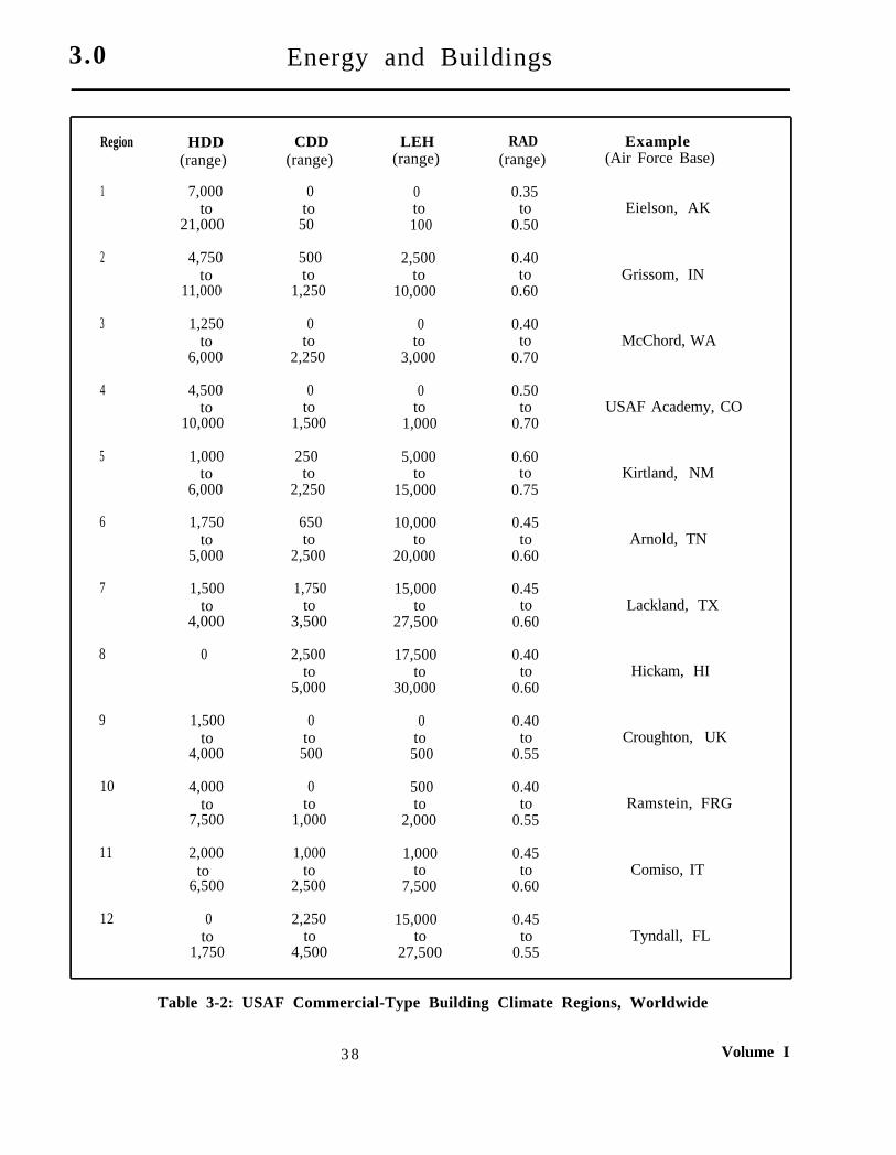
Using these four climate variables results in 12 climate regions,worldwide, for use in planning commercial-type buildings.These regions are illustrated by the data in Table 3-2 on thefollowing page.
A set of maps showing each climate region and the air bases inthe region can be found in Appendix A.
Climate Regions
Appendix A: USAFCommercial-Type BuildingClimate Regions, Worldwide
For the most part, buildings do not use energy, people do.Heating, cooling, lighting, and ventilation adjustments are madein response to people’s needs and desires. Those needs varydepending upon the activity being performed and the climate inwhich the building is located.
Introduction To Passive Solar Concepts 37
Energy ResponsiveBui ld ings
3.0 Energy and Buildings
Region
1
2
3
4
5
6
7
8
9
10
11
12
HDD(range)
7,000to
21,000
4,750to
11,000
1,250to
6,000
4,500to
10,000
1,000to
6,000
1,750to
5,000
1,500to
4,000
0
1,500to
4,000
4,000to
7,500
2,000to
6,500
0to
1,750
CDD LEH(range) (range)
0 0to to
50 100
500 2,500to to
1,250 10,000
0 0to to
2,250 3,000
0 0to to
1,500 1,000
250 5,000to to
2,250 15,000
650 10,000to to
2,500 20,000
1,750 15,000to to
3,500 27,500
2,500 17,500to to
5,000 30,000
0 0to to500 500
0 500to to
1,000 2,000
1,000 1,000to to
2,500 7,500
2,250 15,000to to
4,500 27,500
RAD(range)
0.35to
0.50
0.40to
0.60
0.40to
0.70
0.50to
0.70
0.60to
0.75
0.45to
0.60
0.45to
0.60
0.40to
0.60
0.40to
0.55
0.40to
0.55
0.45to
0.60
0.45to
0.55
Example(Air Force Base)
Eielson, AK
Grissom, IN
McChord, WA
USAF Academy, CO
Kirtland, NM
Arnold, TN
Lackland, TX
Hickam, HI
Croughton, UK
Ramstein, FRG
Comiso, IT
Tyndall, FL
Table 3-2: USAF Commercial-Type Building Climate Regions, Worldwide
3 8 Volume I
Energy and Buildings 3 . 0
Energy use is usually divided into several energy end usecomponents for detailed analysis. In this handbook, energy enduse is divided into the following categories: Energy End Use Categories
(1) heating(2) cooling(3) lighting(4) ventilation(5) process loads
Energy Use Per UnitOf Floor Area: Btu/sf-yrEnergy use by each end use category can be measured in terms of
total energy, such as 450,000,000 Btu’s per year, or it can beconsidered in terms of energy use per unit of floor area, such as45,000 Btu’s per square foot per year. Throughout this handbook,energy use per unit of area will be used as a measure of energyuse in different building types, sizes, and climate regions.
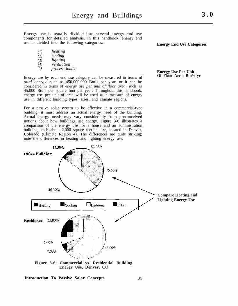
For a passive solar system to be effective in a commercial-typebuilding, it must address an actual energy need of the building.Actual energy needs may vary considerably from preconceivednotions about how buildings use energy. Figure 3-6 illustrates acomparison of the energy use for a house and an administrationbuilding, each about 2,000 square feet in size, located in Denver,Colorado (Climate Region 4). The differences are quite striking;note the differences in heating and lighting energy use.
Compare Heating andLighting Energy Use
Figure 3-6: Commercial vs. Residential BuildingEnergy Use, Denver, CO
Introduction To Passive Solar Concepts 39
3.0 Energy and Buildings
An appropriate passive solar system for the house will be quitedifferent from the appropriate passive solar solutions for theadministration building of the same size.
Commercial-type buildings range in size from small (1,000 sf) toquite large (100,000 sf) and range in use from administrationfacilities to warehouses, from dormitories to fire stations.Therefore, it is not surprising that the range of possible solutionsto the energy needs of these different building types will also bequite varied. In buildings of such varied size and use, theapplication of solar technologies is termed “making the buildingclimate adapted,” that is, making the building more responsiveto the energy savings associated with using the climate to bestadvantage. Climate adapting a building can include suchdiverse concepts as shading the building from the sun, using thesun for heat and light, or using the prevailing breezes to cool thebuilding. Any or all of these solutions might be appropriatedepending upon the building type, its size, and climate region.
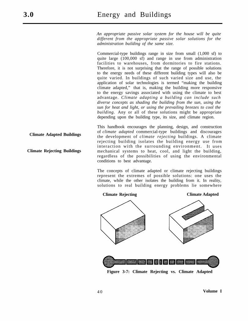
Climate Adapted Buildings
Climate Rejecting Buildings
This handbook encourages the planning, design, and constructionof climate adapted commercial-type buildings and discouragesthe development of climate rejecting buildings. A climaterejecting building isolates the building energy use frominteract ion with the surrounding environment . I t usesmechanical systems to heat, cool, and light the building,regardless of the possibilities of using the environmentalconditions to best advantage.
The concepts of climate adapted or climate rejecting buildingsrepresent the extremes of possible solutions: one uses theclimate, while the other isolates the building from it. In reality,solutions to real building energy problems lie somewhere
Climate Rejecting Climate Adapted
Figure 3-7: Climate Rejecting vs. Climate Adapted
4 0 Volume I
Energy and Buildings 3.0
Energy use and energy economics may make some passiveconcepts attractive and others impractical when consideredwithin the constraints of a project’s needs, fuel availability, andbudgetary requirements. Therefore, some compromise isexpected, and the planner or designer should keep in mind thatthe final solution may be a combination of climate adapted andrejecting concepts.
Two primary characteristics of each building type have a majorimpact upon the overall energy use:
(1) envelope loads(2) internal loads
Envelope LoadsEnvelope loads are associated with energy transfer through thebuilding shell. In some building types, such as single familydetached housing or a warehouse, envelope loads are the singledominant energy transfer.
Internal LoadsInternal loads can be divided into two subcategories: (1) thosedue to occupancy, and (2) those due to lighting and processenergy use. It is primarily the variation in internal loadcharacteristics that determines which passive solar systems willbe most effective in commercial-type buildings.
Each building type has specific occupancy characteristics thatcan be expressed in terms of people loads, period of operation,hours of operation, and schedules. The people load is an estimateof the number of people in the building. This varies considerablyfrom one bui lding type to another . F o r e x a m p l e , a nadministration building is assumed to house one person per 65square feet, while a warehouse typically has one person per 4,000square feet. The period of operation is a designation of whetherthe building is open during the daytime, at night, or both. Anadministration building is usually open only during the day,while a warehouse may be used day and night. The hours ofoperation are the average number of hours per day that thebuilding is occupied, while the schedule is the number of days perweek the building is occupied. An administration building istypically occupied 10 hours a day, 5 days a week, while awarehouse may be occupied 24 hours a day, 7 days a week.
Energy use associated with lighting and process loads (coffeepots, vending machines, etc.) make up the second major internalload category. In most commercial-type buildings, these loads areassumed to be continuous during the occupied period of each day.For example, a continuous lighting load is one in which theelectric lights are turned on in the morning and off at night andstay on all day long. It is the continuous nature of these internalloads that make them so critical to the overall energy use andcosts of the building.
A fair amount of variation exists in these internal loadcharacteristics; however, each of the building types typically
Introduction To Passive Solar Concepts 4 1
3.0 Energy and Buildings
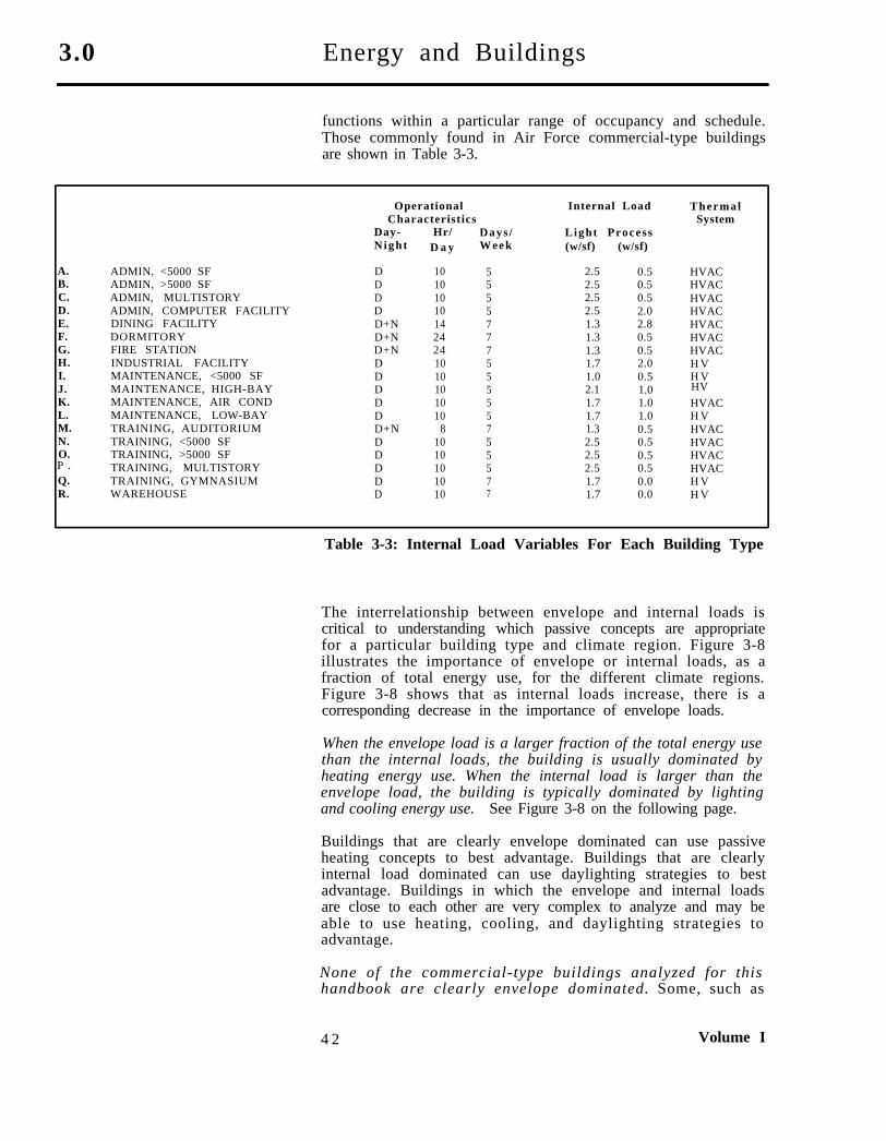
functions within a particular range of occupancy and schedule.Those commonly found in Air Force commercial-type buildingsare shown in Table 3-3.
OperationalCharacteristics
Internal Load ThermalSystem
A.B.C.D.E.F.G.H.I.J.K.L.M.N.O.
Q.R.
ADMIN, <5000 SFADMIN, >5000 SFADMIN, MULTISTORYADMIN, COMPUTER FACILITYDINING FACILITYDORMITORYFIRE STATIONINDUSTRIAL FACILITYMAINTENANCE, <5000 SFMAINTENANCE, HIGH-BAYMAINTENANCE, AIR CONDMAINTENANCE, LOW-BAYTRAINING, AUDITORIUMTRAINING, <5000 SFTRAINING, >5000 SFTRAINING, MULTISTORY
HV
P .TRAINING, GYMNASIUMWAREHOUSE
Day- Hr/Night D a y
D 10D 10D 10D 10D+N 14D+N 24D+N 24D 10D 10D 10D 10D 10D+N 8D 10D 10D 10D 10D 10
Days /Week
555577755555755577
Light Process(w/sf) (w/sf)
2.5 0.52.5 0.52.5 0.52.5 2.01.3 2.81.3 0.51.3 0.51.7 2.01.0 0.52.1 1.01.7 1.01.7 1.01.3 0.52.5 0.52.5 0.52.5 0.51.7 0.01.7 0.0
HVACHVACHVACHVACHVACHVACHVACH VH V
HVACH VHVACHVACHVACHVACH VH V
Table 3-3: Internal Load Variables For Each Building Type
The interrelationship between envelope and internal loads iscritical to understanding which passive concepts are appropriatefor a particular building type and climate region. Figure 3-8illustrates the importance of envelope or internal loads, as afraction of total energy use, for the different climate regions.Figure 3-8 shows that as internal loads increase, there is acorresponding decrease in the importance of envelope loads.
When the envelope load is a larger fraction of the total energy usethan the internal loads, the building is usually dominated byheating energy use. When the internal load is larger than theenvelope load, the building is typically dominated by lightingand cooling energy use. See Figure 3-8 on the following page.
Buildings that are clearly envelope dominated can use passiveheating concepts to best advantage. Buildings that are clearlyinternal load dominated can use daylighting strategies to bestadvantage. Buildings in which the envelope and internal loadsare close to each other are very complex to analyze and may beable to use heating, cooling, and daylighting strategies toadvantage.
None of the commercial-type buildings analyzed for thishandbook are clearly envelope dominated. Some, such as
4 2 Volume I

Energy and Buildings 3 . 0
warehouses or dormitories, have an almost equal balancebetween envelope and in ternal loads . Others , such asadministration buildings and dining facilities, are dominated bytheir internal loads. This means that many of the traditionalpassive heating concepts associated with the phrase “passivesolar” are not going to be effective in these buildings.Recognizing that commercial-type buildings are complex andrespond differently to the environment than do more simplebuildings (such as houses), makes it easier to find theappropriate passive solution to the energy needs of the building.
Envelope vs. Internal Loads
Figure 3-8: Internal vs. Envelope Loads
Energy costs represent another way to consider the impact ofenergy use in buildings. The impact of different fuels used forheating (such as electricity, natural gas, or fuel oil) as well as thecosts of electricity for cooling and lighting a building can provideanother important clue as to what kinds of passive concepts aremost effective in commercial-type buildings.
Energy Costs
In this handbook, energy costs are considered in terms of costs(in dollars) per square foot of building area per year. Thus, anenergy cost of $1.00/sf-yr in a 10,000 sf building would meanthat the building costs $10,000 per year to heat, cool, light, andso forth. Using a cost per unit of area measure allows one tocompare the energy costs of different building types or differentsizes of the same building type.
In large nonresidential buildings, no direct link between energyuse and energy costs exists. Put another way, saving energy isnot directly proportional to saving energy costs. This is astartling revelation to many people who are not familiar with
Introduction To Passive Solar Concepts 4 3
3.0 Energy and Buildings
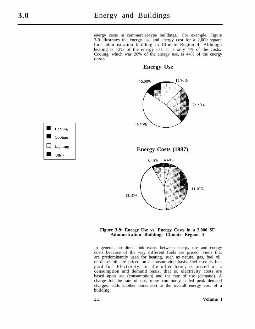
energy costs in commercial-type buildings. For example, Figure3-9 illustrates the energy use and energy cost for a 2,000 squarefoot administration building in Climate Region 4. Althoughheating is 13% of the energy use, it is only 4% of the costs.Cooling, which was 26% of the energy use, is 44% of the energycosts.
Energy Use
Energy Costs (1987)
Figure 3-9: Energy Use vs. Energy Costs in a 2,000 SFAdministration Building, Climate Region 4
In general, no direct link exists between energy use and energycosts because of the way different fuels are priced. Fuels thatare predominantly used for heating, such as natural gas, fuel oil,or diesel oil, are priced on a consumption basis; fuel used is fuelpaid for. Electricity, on the other hand, is priced on aconsumption and demand basis; that is, electricity costs arebased upon use (consumption) and the rate of use (demand). Acharge for the rate of use, more commonly called peak demandcharges, adds another dimension to the overall energy cost of abuilding.
4 4 Volume I
Energy and Buildings 3 . 0
Peak demand charges can be found in more than 80% of allutility company rate schedules in the United States, and close to100% of all utilities outside the United States. Peak demandcharges represent the costs associated with building andmaintaining generation plants, distribution networks, andtransformers used by utilities to provide electricity.
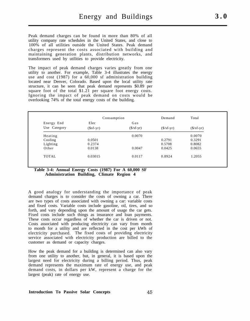
The impact of peak demand charges varies greatly from oneutility to another. For example, Table 3-4 illustrates the energyuse and cost (1987) for a 60,000 sf administration buildinglocated near Denver, Colorado. Based upon the local utility ratestructure, it can be seen that peak demand represents $0.89 persquare foot of the total $1.21 per square foot energy costs.Ignoring the impact of peak demand on costs would beoverlooking 74% of the total energy costs of the building.
Energy EndUse Category
Consumption Demand Total
Elec Gas($sf-yr) ($/sf-yr) ($/sf-yr) ($/sf-yr)
Heat ing 0.0070 0.0070Cooling 0.0501 0.2791 0.3291Lighting 0.2374 0.5708 0.8082Other 0.0138 0.0047 0.0425 0.0655
TOTAL 0.03015 0.0117 0.8924 1.2055
Table 3-4: Annual Energy Costs (1987) For A 60,000 SFAdministration Building, Climate Region 4
A good analogy for understanding the importance of peakdemand charges is to consider the costs of owning a car. Thereare two types of costs associated with owning a car: variable costsand fixed costs. Variable costs include gasoline, oil, tires, and soforth, and vary depending upon the amount of usage the car gets.Fixed costs include such things as insurance and loan payments.These costs occur regardless of whether the car is driven or not.Costs associated with producing electricity can vary from monthto month for a utility and are reflected in the cost per kWh ofelectricity purchased. The fixed costs of providing electricityservice associated with electricity production are billed to thecustomer as demand or capacity charges.
How the peak demand for a building is determined can also varyfrom one utility to another, but, in general, it is based upon thelargest need for electricity during a billing period. Thus, peakdemand represents the maximum rate of energy use, and peakdemand costs, in dollars per kW, represent a charge for thelargest (peak) rate of energy use.
Introduction To Passive Solar Concepts
3.0 Energy and Buildings
The rate of electrical energy use, in kW, is different than theconsumption of electricity, in kWh. An analogy for understandingthe concept of peak demand as representative of the rate ofenergy use is to consider using either a fire hose or a garden hoseto fill a 5-gallon water bucket. Using either hose, the totalquantity of water in the bucket is eventually 5 gallons, that is,the water “consumed” is 5 gallons. However, the “rate ofconsumption” for a 3/4-inch garden hose is quite a bit less thanthe rate for a 3-inch fire hose. Thus, for either hose, the totalquantity of water in the bucket is 5 gallons, however, the firehose fills the bucket much faster than the garden hose.
Suppose two identical buildings consume 20,000 kWh ofelectricity in a month. However, one building has a peak demandof 5 kW and the other a peak demand of 500 kW. It is clear thatthe utility has to be able to maintain a power plant that has thecapacity to produce 505 kW of electricity to be able to meet theneeds of the two buildings, regardless of the fact that they areboth consuming 20,000 kWh. If the utility rate structure is $0.10per kWh for electricity and $10.00 per kW for peak demand, thenthe building with a 5 kW peak demand has a monthly utility billof $2,050. The building with the 500 kW peak demand has autility bill of $7,000. Although the two buildings consume thesame quantity of energy (20,000 kWh), their monthly bills arequite different.
Save energy and energy costA properly designed passive solar building is one that saves bothenergy use and energy costs. However, a primary purpose of thishandbook is to save energy costs. The possibility of savingenergy costs without reducing energy use or by increasing energyuse will also be considered. Saving energy costs withoutreducing energy use can occur if the peak demand for a buildingcan be reduced. For example, in the previous example, supposethe demand were reduced from 500 kW to 250 kW. Then theenergy costs would be reduced from $7,000 to $4,500 even if thereis no reduction in energy usage (it is still 20,000 kWh).
Saving energy costs by increasing energy use can occur in twoways. First, by decreasing the peak demand but simultaneouslyincreasing the consumption of electricity, it is possible to reducethe overall cost of energy in a building. For example, suppose the500 kW building could have the peak demand reduced to 100 kWif it “costs” an additional 10,000 kWh. Thus, the total electricitycosts would be based upon 30,000 kWh and 100 kW. Totalelectricity costs would be $4,000, down from $7,000.
The second way to reduce energy costs by increasing energy useis to switch fuel, that is, change from a more costly fuel to a lessexpensive fuel. A good example of this is to use natural gasinstead of electricity to heat a building. Even though natural gasheating is less efficient than electric heating, the cost differentialassociated with the two fuels usually makes it cheaper to usen a t u r a l g a s r a t h e r t h a n e l e c t r i c i t y . A l t h o u g h s p e c i a lcircumstances may make it difficult or impossible to trade off onefuel for another, it is a viable alternative that should beconsidered during the comprehensive planning process.
4 6 Volume I
Suggested Additional Reading 4.0
The following are a selection of books and Air Force documents Introduct ionthat are suggested as additional reading to better understandpass ive solar energy sys tems. The books range f romnontechnical to engineering texts.
Concepts and Practice of Architectural Daylighting, FullerMoore, New York: Van Nostrand Reinhold, 1985. ISBN 0-442-26439-9.
Dayl ight inga n dLight ing
Daylighting Design and Analysis, Claude L. Robbins, NewYork: Van Nostrand Reinhold, 1986. ISBN 0-442-27949-3.
Illuminating Engineering Society Handbook, Volumes 1a n d 2 , Edi to r : J . Kau fman , New York : I l l umina t i ngEngineering Society, 1985.
Illumination Engineering: From Edison’s Lamp to theLaser, Joseph B. Murdoch, New York: Macmillan, 1985. ISBN 0-02-948580-0.
Interior Lighting for Environmental Designers, James L.Nuckolls, New York: Wiley-Interscience, 1976. ISBN 0-471-65163-X.
The Lighting of Buildings, Hopkinson and Kay, London: Faberand Faber. 1972.
R e c o m m e n d e d P r a c t i c e o f D a y l i g h t i n g , I l l umina t ingEngineering Society, New York: Illuminating EngineeringSociety, 1979. PR-5.
Sunlight as Formgiver for Architecture, William Lam, NewYork: Van Nostrand Reinhold. 1986. ISBN 0-442-25941-7.
The Passive Solar Energy Book (Expanded ProfessionalEdition), Edward Mazria, Emmaus, PA: Rodale Press, 1979.ISBN 0-87857-238-4.
Passive SolarThermal
Passive Solar Heating Analysis, American Society of Heating,Refrigerating and Air Conditioning Engineers, New York:ASHRAE, 1985.
T h e S o l a r C o o l i n g H a n d b o o k , Editor : Harry Mil ler ,Proceedings of the Passive Cooling Workshop, Amherst MA,1981.
Introduction To Passive Solar Concepts 4 7

4.0 Suggested Additional Reading
Solar Envelope Concepts: Moderate Density BuildingApplications, Knowles and Berry, U.S. Department of Energy,Golden, CO: Solar Energy Research Institute, 1980. SERI/SP-98155-1.
Bui ld ingsa n d
Energy
ASHRAE Handbook of Fundamentals, American Society ofHeating, Refrigerating and Air Conditioning Engineers, NewYork: ASHRAE. 1985.
ASHRAE Systems Handbook, American Society of Heating,Refrigerating and Air Conditioning Engineers, New York:ASHRAE, 1984.
The Design of Energy Responsive Commercial Buildings,Ternoey, Bickle, Robbins, Busch, and McCord, New York: Wileyand Sons, 1985. ISBN 0-471-80463-0.
Mechanical and Electrical Equipment For Buildings, 7 thEdition, McGuinness, Stein, and Reynolds, New York: Wiley andSons, 1985. ISBN 0-471-58432-0.
Small Office Building Handbook, Burt-Hill-Kosar-RittelmannAssociates, New York: Van Nostrand Reinhold, 1985. ISBN 0-442-21126-0.
Sun, Wind, and Light: Architectural Design Strategies, G .Brown, New York: Wiley and Sons, 1985. ISBN 0-471-82063-6.
United StatesAir Force
D o c u m e n t s
Base Comprehensive Planning, Land Use Planning Bulletin:HQ USAF/LEEVX.
Engineering Weather Data, AFM 88-29.
Engineering Technical Letter (ETL): Energy EfficientEquipment.
Engineering Technical Letter (ETL): Normal Passive SolarApplications.
Engineering Technical Letter (ETL): Unique Passive SolarApplications.
Engineering Technical Letter (ETL): Solar Applications inMedical Facilities.
Engineering Technical Letter (ETL): Computer EnergyAnalysis.
Engineering Technical Letter (ETL): Energy Budget Figures.
4 8 Volume I
Suggested Additional Reading 4 . 0
Engineering Technical Letter (ETL): Energy Managementand Control Systems (EMCS).
Engineering Technical Letter (ETL): Solar Applications.
Installation Design, AFM 88-43.
Insolation Data Manual, Knapp, Stoffel, and Whitaker. U.S. Other Sources ofDepartment of Energy, Golden, CO: Solar Energy ResearchInstitute, 1981. SERI/SP-755-789. Informat ion
Renewable Energy Technology Handbook for Mili taryEngineers, Golden CO: Solar Energy Research Institute, 1981.
Solar Energy Dictionary, V. Hunt, New York: Industrial Press,1982. ISBN 0-8311-1139-9.
Introduction To Passive Solar Concepts 4 9
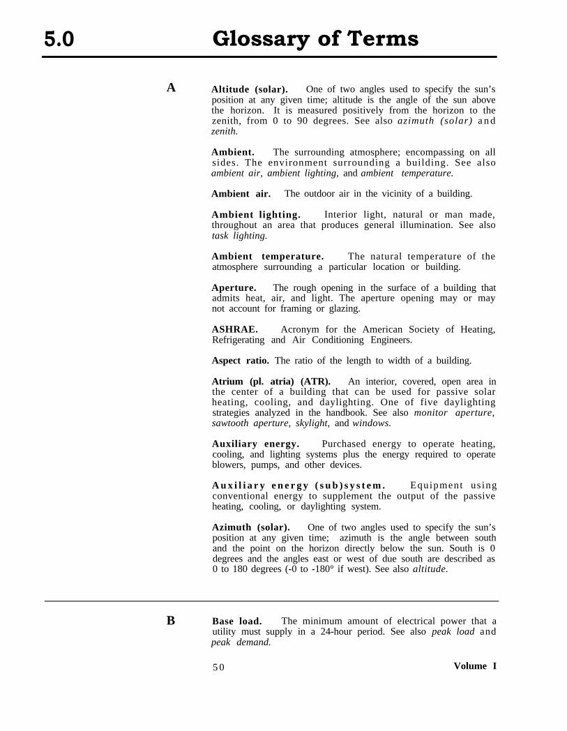
5.0 Glossary of Terms
A Altitude (solar). One of two angles used to specify the sun’sposition at any given time; altitude is the angle of the sun abovethe horizon. It is measured positively from the horizon to thezenith, from 0 to 90 degrees. See also azimuth (solar) a n dzenith.
Ambient. The surrounding atmosphere; encompassing on allsides. The environment surrounding a building. See alsoambient air, ambient lighting, and ambient temperature.
Ambient air. The outdoor air in the vicinity of a building.
Ambient lighting. Interior light, natural or man made,throughout an area that produces general illumination. See alsotask lighting.
Ambient temperature. The natural temperature of theatmosphere surrounding a particular location or building.
Aperture. The rough opening in the surface of a building thatadmits heat, air, and light. The aperture opening may or maynot account for framing or glazing.
ASHRAE. Acronym for the American Society of Heating,Refrigerating and Air Conditioning Engineers.
Aspect ratio. The ratio of the length to width of a building.
Atrium (pl. atria) (ATR). An interior, covered, open area inthe center of a building that can be used for passive solarheating, cooling, and daylighting. One of five daylightingstrategies analyzed in the handbook. See also monitor aperture,sawtooth aperture, skylight, and windows.
Auxiliary energy. Purchased energy to operate heating,cooling, and lighting systems plus the energy required to operateblowers, pumps, and other devices.
A u x i l i a r y e n e r g y ( s u b ) s y s t e m . Equipment us ingconventional energy to supplement the output of the passiveheating, cooling, or daylighting system.
Azimuth (solar). One of two angles used to specify the sun’sposition at any given time; azimuth is the angle between southand the point on the horizon directly below the sun. South is 0degrees and the angles east or west of due south are described as0 to 180 degrees (-0 to -180° if west). See also altitude.
B Base load. The minimum amount of electrical power that autility must supply in a 24-hour period. See also peak load andpeak demand.
5 0 Volume I
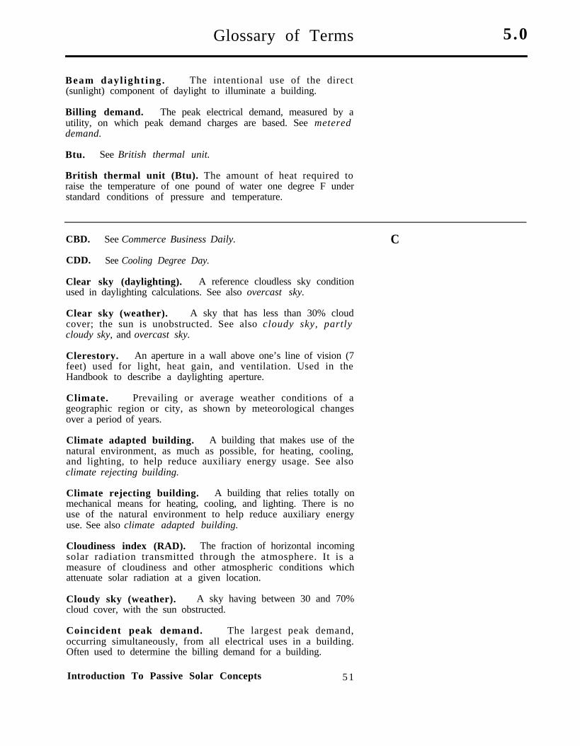
Glossary of Terms 5.0
Beam dayl ight ing. The intentional use of the direct(sunlight) component of daylight to illuminate a building.
Billing demand. The peak electrical demand, measured by autility, on which peak demand charges are based. See metereddemand.
Btu. See British thermal unit.
British thermal unit (Btu). The amount of heat required toraise the temperature of one pound of water one degree F understandard conditions of pressure and temperature.
CBD. See Commerce Business Daily. C
CDD. See Cooling Degree Day.
Clear sky (daylighting). A reference cloudless sky conditionused in daylighting calculations. See also overcast sky.
Clear sky (weather). A sky that has less than 30% cloudcover; the sun is unobstructed. See also cloudy sky, partlycloudy sky, and overcast sky.
Clerestory. An aperture in a wall above one’s line of vision (7feet) used for light, heat gain, and ventilation. Used in theHandbook to describe a daylighting aperture.
Climate. Prevailing or average weather conditions of ageographic region or city, as shown by meteorological changesover a period of years.
Climate adapted building. A building that makes use of thenatural environment, as much as possible, for heating, cooling,and lighting, to help reduce auxiliary energy usage. See alsoclimate rejecting building.
Climate rejecting building. A building that relies totally onmechanical means for heating, cooling, and lighting. There is nouse of the natural environment to help reduce auxiliary energyuse. See also climate adapted building.
Cloudiness index (RAD). The fraction of horizontal incomingsolar radiation transmitted through the atmosphere. It is ameasure of cloudiness and other atmospheric conditions whichattenuate solar radiation at a given location.
Cloudy sky (weather). A sky having between 30 and 70%cloud cover, with the sun obstructed.
Coincident peak demand. The largest peak demand,occurring simultaneously, from all electrical uses in a building.Often used to determine the billing demand for a building.
Introduction To Passive Solar Concepts 51
5.0 Glossary of Terms
Collection. The process of trapping energy for use as heat(passive solar thermal system) or light (daylighting system).
Commerce Business Daily. A daily publication of the U.S.Department of Commerce listing all goods and services to bepurchased by the U.S. government.
Commercial-type buildings. A term used by the UnitedStates Air Force to describe all nonresidential, institutional, andindustrial buildings.
Control. That part of a passive solar thermal or daylightingsystem used to manage temperatures, air movement, or thequantity of light in a space.
Conventional building. The name given a building that doesnot use any passive solar strategies to reduce energy use andenergy costs.
Cooling Degree Day (CDD). A measure of the need forcooling. The number of cooling degree days in a single day isdetermined by subtracting the reference temperature from theaverage temperature for the day. See Heating Degree Day.
D D+S. See direct gain plus storage.
Daylight. The light from the sun and (clear or overcast) skyused to illuminate the interior of buildings.
Daylighting. The use of natural lighting from the sun and(clear or overcast) sky as a supplement to electric lighting inbuildings.
DD Form 1391. The form used by the Department of Defenseentitled “Military Construction Project Data” to specify a facilityrequirement, including estimated costs.
Degree Day. See heating degree day and cooling degree day.
Design Instructions (DIs). Provide authority to the designmanager, through the AFRCE, to initiate the facility designprocess.
DG. See direct gain.
DI’s. See design instructions.
Direct gain (DG). A passive system where the sun heats thefloor or walls of the building directly, through appropriatelyplaced apertures. The building does not have any additionalinternal mass beyond normal construction practices. One of fourpassive heating strategies analyzed in the handbook. See directgain plus storage, indirect gain, and sunspace.
5 2 Volume I
Glossary of Terms 5 . 0
Direct gain plus storage (D+S). A passive system where thesun heats the floor or walls of the building directly throughappropriately placed apertures. The building has additionalinternal mass beyond normal construction practices for a givenbuilding type. One of four passive heating strategies analyzed inthe handbook. See direct gain, indirect gain, and sunspace.
Distribution. Moving heat, air, and daylight to where theyare needed in a building.
Energy budget. The quantity of energy, usually in Btu’s persquare-foot per year (Btu/sf-yr), allocated to a building or end use Ecategory.
Energy end use. The amount of energy used by a specific enduse category of the building. In this handbook, end usecategories are heating, cooling, lighting, process, a n dventilation.
Envelope loads. The heating and cooling energy useassociated with the energy gains and losses through the shell(envelope) of the building.
Erg. The CGS (centimeter-gram-second) unit of work equal tothe work done by a force of one dyne acting through a distance ofone centimeter. Equal to approximately 1,050 Btu’s.
Facade. The front of a building; any face of a building givenspecial architectural consideration.
fc. See footcandle.
Fenestration. Arrangements, proportions, and design ofwindows in a building.
Footcandle (fc). The non-SI unit of measure of illuminance.One footcandle is equal to one lumen per square foot. Seeilluminance and lux.
Form 254 (Standard Form 254). U.S. government formentitled “Architect-Engineer and Related Services Questionnaire”used to record the experience and capabilities of architecturaland engineering firms.
Form 255 (Standard Form 255). U.S. government formentitled “Architect-Engineer and Related Services Questionnairefor Specific Project” used to record the experience andcapabilities of architectural and engineering firms on a specificproject.
F
Introduction To Passive Solar Concepts 53
5.0 Glossary of Terms
G Glare. The sensation produced by luminance within the visualfield that is sufficiently greater than the luminance to which theeyes are adapted to cause annoyance, discomfort, or loss of visualperformance and visibility.
Greenhouse. See sunspace.
H HDD. See Heating Degree Day.
Heat storage. See storage.
Heating Degree Day (HDD). A measure of the need forheating. The number of heating degree days in a single day isdetermined by subtracting the average temperature from thereference temperature for the day.
Heating-Ventilating system (HV). A mechanical systemdesigned for heating and ventilating only; no mechanical coolingcapability. This type of system is commonly used in industrialand maintenance facilities.
Heating-Ventilating-Air Conditioning system (HVAC). Amechanical system designed for heating, ventilating, and airconditioning a building. For example, this type of system iscommonly used in administration facilities.
HV. See heating-ventilating system.
HVAC. See heating-ventilating-air conditioning system.
I IES. Acronym for the Illuminating Engineering Society.
Illuminance. The density of the luminous flux incident on asurface, in lumens per unit of area. See footcandle and lux.
Illumination. The act of being illuminated.
IND. See indirect gain solar system.
Indirect gain (IND) solar system. Passive heating system inwhich the collection and storage components are part of the samebuilding element, wall or roof. The sunlight passes through thecollector aperture to heat the storage component. Conductionthrough the storage component brings the heat to the insidesurface where it is distributed to the space by radiation andconvection. One of four passive heating strategies analyzed inthe handbook. See also direct gain, direct gain plus storage, andsunspace.
5 4 Volume I
Glossary of Terms 5.0
Internal gains. Combined heat release from all heat sources(including lighting, people, and process loads) in a building otherthan its heating system.
Internal loads. The heating, cooling, lighting, ventilation,and process loads of a building associated with the interiorspaces. See envelope loads and internal gains.
Irradiance. The density of the radiant flux incident on asurface, in Btu’s per square foot or watts per square meter.
Isolated solar system. See sunspace.
Joule (J). The absolute SI unit of work or energy that equals J107 ergs. See erg.
Kilowatt (kW). A unit of power equal to 1,000 watts. The rateof flow of energy into a building. See peak demand.
K
Kilowatt-hour (kWh). The time rate of flow of electricity inone hour. Equal to 3,413 Btu’s.
kW. See kilowatt.
kWh. See kilowatt-hour.
Latent Enthalpy Hour (LEH). The number of hours inwhich the energy requirement for removing moisture from the air Lis greater than that for the upper extremes of the ASHRAEthermal comfort zone.
LEH. See Latent Enthalpy Hour.
Light. Radiant energy that is capable of exciting the retina ofthe eye and producing visual sensation. Radiation in thespectrum of 380 nanometers to 780 nanometers, where ananometer is 10-9 meters.
Light court. An uncovered, interior, open area in the center ofa building. See also atrium.
lm. See Lumen
Lumen (lm). The SI and non-S1 unit of luminous flux, that is,the visible energy exitant a light source.
Introduction To Passive Solar Concepts 55
5.0 Glossary of Terms
Lux (lx). The SI unit of measure of illuminance. One lux isequal to one lumen per square meter. See illuminance a n dfootcandle.
lx. See lux.
M Metered demand. The measured total coincident electricaldemand in a building. See also billing demand.
MON. See monitor aperture.
Monitor aperture (MON). A raised portion of the roof of abuilding which has apertures on opposing surfaces. Commonlyused in passive heating and daylighting systems. One of fivedaylighting strategies analyzed in the handbook. See alsoatrium, sawtooth aperture, skylight, and windows.
N Natural light. See daylight.
Natural ventilation (NVN). The unassisted movement of airthrough a building. Can be caused by pressure or temperaturedifferences between the outside and inside air. One of twopassive cooling strategies analyzed in the handbook. See alsonight mechanical ventilation.
Night mechanical ventilation (NMV). The mechanicalventilation of the mass of the building at night to help reducedaytime cooling loads and cooling peak demand. One of twopassive cooling strategies analyzed in the handbook. See alsonatural ventilation.
NMV. See night mechanical ventilation.
NVN. See natural ventilation.
O Operating schedule. The portion of the workday that abuilding is typically occupied.
Orientation. The relationship of a building surface withrespect to compass heading. Usually expressed as either acompass heading or a degree heading.
Overcast sky (daylighting). A sky with 100% cloud cover.The sun is obstructed and clouds extend to the horizon in alldirections. See also clear sky, cloudy sky, and partly cloudy sky.
5 6 Volume I
Glossary of Terms 5.0
Partly cloudy sky (weather). A sky that has intermittentc louds in which the sun is a l ternate ly obst ructed andunobstructed. See also clear sky, cloudy sky, and overcast sky.
P
Passive solar system. A heating, cooling, or daylightingsystem that operates without mechanical devices to collect, store,and distribute energy in a building.
Peak cooling. The peak cooling load in a building; measuredin Btu’s or kW’s. See peak demand.
Peak demand. The maximum rate of electricity usage by autility customer during a 15 or 30 minute time period. See alsobilling demand.
Project book. A document containing data, criteria,functional requirements, and cost information to supportprogramming and design of Air Force facilities.
RAD. See Cloudiness Index. Q, R
Savings-to-investment ratio (SIR). Used by the Air Forceto determine the economic viability of passive solar energysystems.
SAW. See sawtooth aperture.
Sawtooth aperture (SAW). A roof aperture system in whichthe glazing is placed on the short, usually vertical, surface of aseries of roof serrations. One of five daylighting strategiesanalyzed in the handbook. See also atrium, monitor aperture,skylight, and windows.
Shading. An effective way to keep a building comfortablethrough cooling load avoidance. Shading is primarily used onapertures to avoid excessive solar gains, but can also be used onfacades to keep walls from being exposed to the sun.
Shading coefficient. The ratio of the solar heat gain througha specific glazing system under a given set of conditions, to thetotal solar heat gain through a single layer of clear, l/S-inchthick, double-strength glass under the same conditions.
Sidelighting. The use of daylight apertures in the walls of abuilding. See windows and clerestories.
SIR. See savings-to-investment ratio.
SKY. See skylight.
Introduction To Passive Solar Concepts 5 7
S
5.0 Glossary of Terms
Skylight (SKY). A roof aperture, typically horizontal, used toilluminate the interior zones of low-rise buildings. One of fivedaylighting strategies analyzed in the handbook. See alsoatrium, monitor aperture, sawtooth aperture, and windows.
Solar envelope. A solar envelope is a three-dimensionalvolume, covering that part of a site that is buildable, withinwhich a building has access to the sun without blocking directsunlight to adjacent buildings or property.
Standard Form 254. See Form 254
Standard Form 255. See Form 255
Storage. Using the mass in the walls or floor of a building tocollect heat during the day for use at night or on cloudy days.
Sunspace. A usable space attached to a building that hasglazing on two or more sides. Air temperatures are allowed tovary more than in the building proper. Sometimes called asolarium, winter garden, or greenhouse. One of four passiveheating strategies analyzed in the handbook. See also directgain, direct gain plus storage, and indirect gain.
T, U Toplighting. The use of daylight apertures on the roof of abuilding. See monitor apertures, sawtooth apertures, a n dskylight.
V Ventilation. The atmospheric air that is purposely allowed toenter an interior space to cool or freshen it.
W Watt (W). The absolute SI unit of power that equals one (1)absolute joule per second.
WIN. See window aperture.
Window aperture (WIN). An aperture in a wall of a building.One of five daylighting strategies analyzed in the handbook. Seealso atrium, monitor aperture, skylight, and sawtooth aperture.
X, Y, Z Zenith. The point at the top of a hemispheric sky dome.
5 8 Volume I
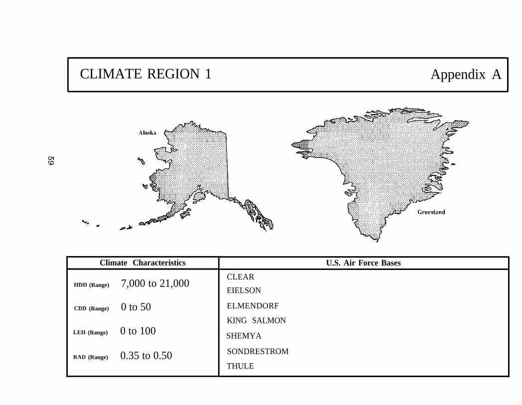
CLIMATE REGION 1 Appendix A
Climate Characteristics
HDD (Range) 7,000 to 21,000
CDD (Range) 0 to 50
LEH (Range) 0 to 100
RAD (Range) 0.35 to 0.50
CLEAR
EIELSON
ELMENDORF
KING SALMON
SHEMYA
SONDRESTROM
THULE
U.S. Air Force Bases
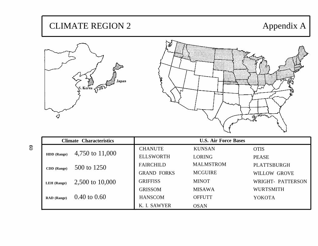
CLIMATE REGION 2 Appendix A
Climate Characteristics
HDD (Range) 4,750 to 11,000
CDD (Range) 500 to 1250
LEH (Range) 2,500 to 10,000
RAD (Range) 0.40 to 0.60
CHANUTE
ELLSWORTH
FAIRCHILD
GRAND FORKS
GRIFFISS
GRISSOM
HANSCOM
K. I. SAWYER
U.S. Air Force Bases
KUNSAN OTIS
LORING PEASEMALMSTROM PLATTSBURGH
MCGUIRE WILLOW GROVE
MINOT WRIGHT- PATTERSON
MISAWA WURTSMITH
OFFUTT YOKOTA
OSAN
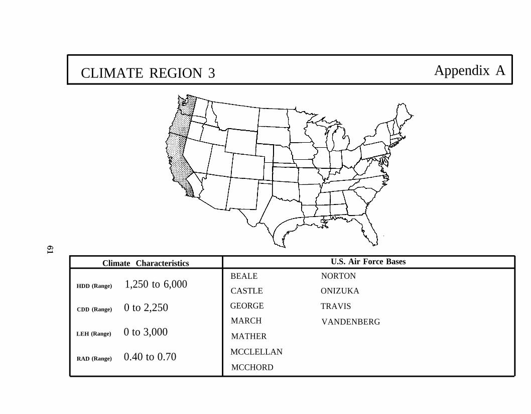
CLIMATE REGION 3 Appendix A
Climate Characteristics U.S. Air Force Bases
HDD (Range) 1,250 to 6,000
CDD (Range) 0 to 2,250
LEH (Range) 0 to 3,000
RAD (Range) 0.40 to 0.70
BEALE NORTON
CASTLE ONIZUKA
GEORGE TRAVIS
MARCH VANDENBERG
MATHER
MCCLELLAN
MCCHORD
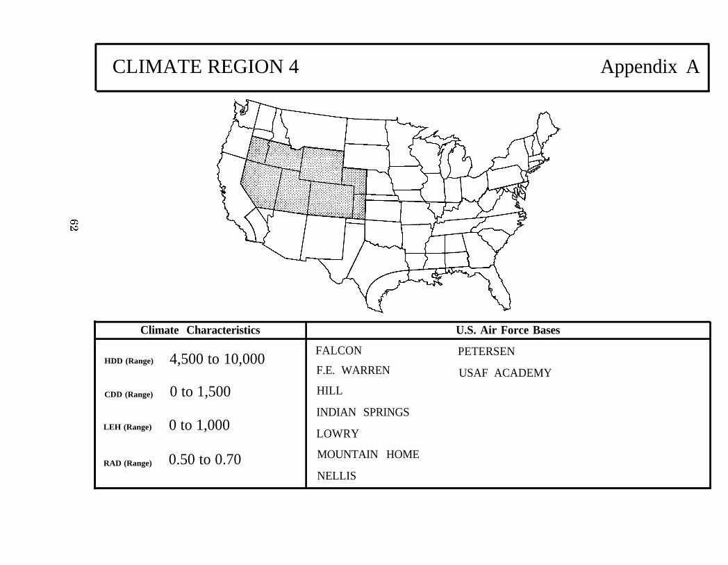
CLIMATE REGION 4 Appendix A
Climate Characteristics
4,500 to 10,000HDD (Range)
CDD (Range) 0 to 1,500
LEH (Range) 0 to 1,000
FALCON
F.E. WARREN
HILL
INDIAN SPRINGS
LOWRY
U.S. Air Force Bases
PETERSEN
USAF ACADEMY
0.50 to 0.70 MOUNTAIN HOMERAD (Range)
NELLIS
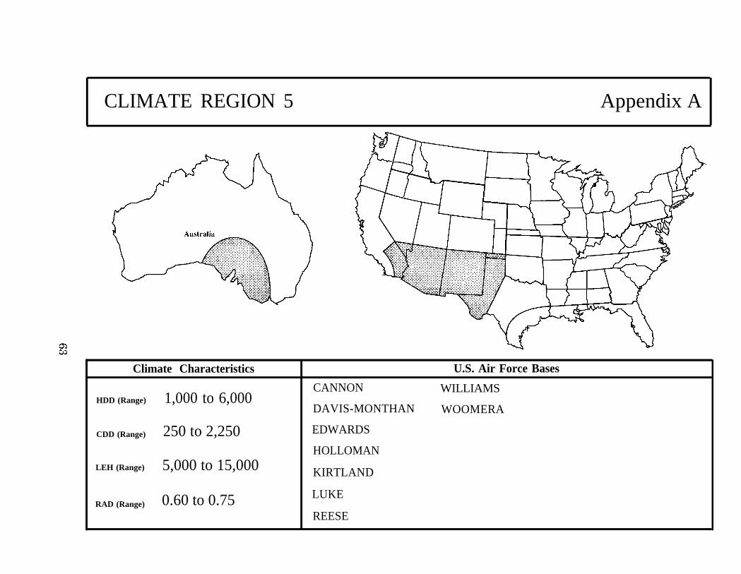
CLIMATE REGION 5 Appendix A
Climate Characteristics
1,000 to 6,000HDD (Range)
CDD (Range) 250 to 2,250
LEH (Range) 5,000 to 15,000
0.60 to 0.75RAD (Range)
CANNON
DAVIS-MONTHAN
EDWARDS
HOLLOMAN
KIRTLAND
LUKE
REESE
U.S. Air Force Bases
WILLIAMS
WOOMERA
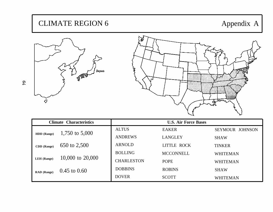
CLIMATE REGION 6 Appendix A
Climate Characteristics
1,750 to 5,000HDD (Range)
CDD (Range) 650 to 2,500
LEH (Range) 10,000 to 20,000
RAD (Range) 0.45 to 0.60
ALTUS
ANDREWS
ARNOLD
BOLLING
CHARLESTON
DOBBINS
DOVER
U.S. Air Force Bases
EAKER SEYMOUR JOHNSON
LANGLEY SHAW
LITTLE ROCK TINKER
MCCONNELL WHITEMAN
POPE WHITEMAN
ROBINS SHAW
SCOTT WHITEMAN

CLIMATE REGION 7 Appendix A
Climate Characteristics
HDD (Range) 1,500 to 4,000
CDD (Range) 1,750 to 3,500
LEH (Range) 15,000 to 27,500
RAD (Range) 0.45 to 0.60
BERGSTROM
BROOKS
CARSWELL
COLUMBUS
DYESS
GOODFELLOW
U.S. Air Force Bases
KELLY
LACKLAND
LAUGHLIN
MAXWELL
RANDOLPH
SHEPPARD
GUNTER VANCE
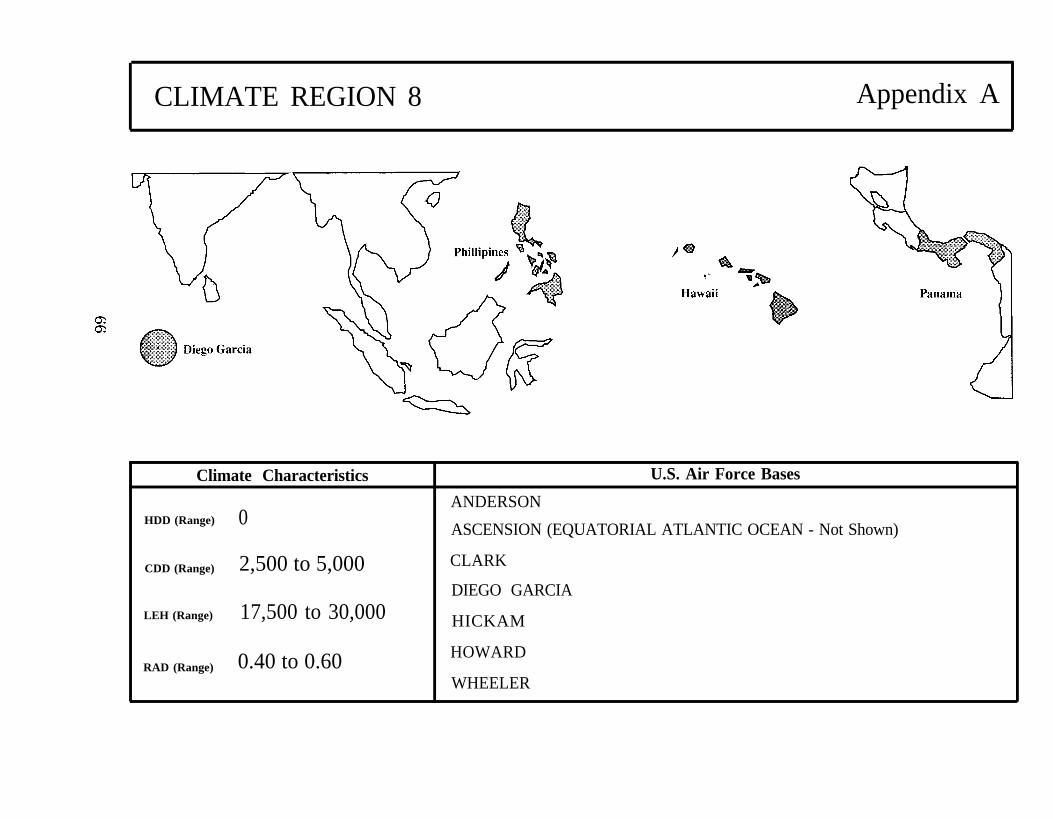
CLIMATE REGION 8 Appendix A
Climate Characteristics
HDD (Range) 0
U.S. Air Force Bases
ANDERSON
ASCENSION (EQUATORIAL ATLANTIC OCEAN - Not Shown)
CDD (Range) 2,500 to 5,000 CLARK
DIEGO GARCIALEH (Range) 17,500 to 30,000 HICKAM
RAD (Range) 0.40 to 0.60 HOWARD
WHEELER
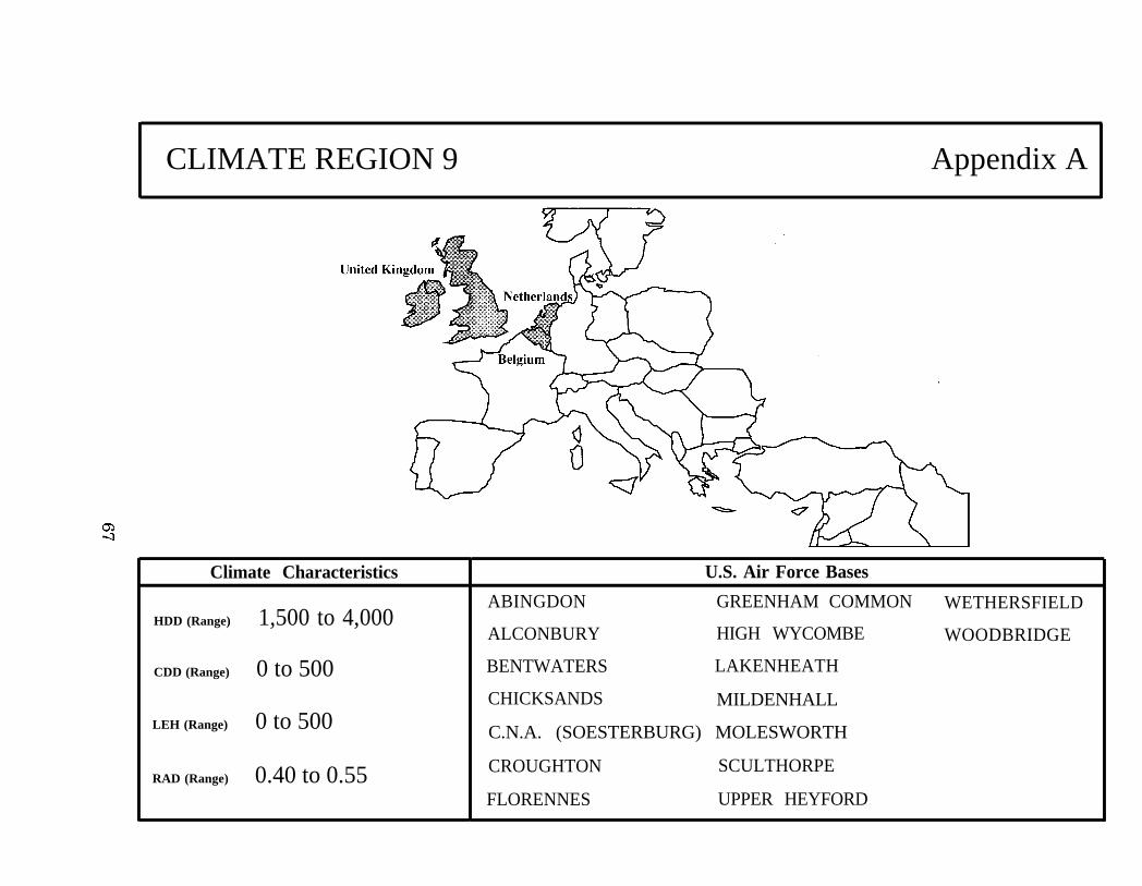
CLIMATE REGION 9 Appendix A
Climate Characteristics
HDD (Range) 1,500 to 4,000
CDD (Range) 0 to 500
LEH (Range) 0 to 500
RAD (Range) 0.40 to 0.55
U.S. Air Force Bases
ABINGDON GREENHAM COMMON WETHERSFIELD
ALCONBURY HIGH WYCOMBE WOODBRIDGE
BENTWATERS LAKENHEATH
CHICKSANDS MILDENHALL
C.N.A. (SOESTERBURG) MOLESWORTH
CROUGHTON SCULTHORPE
FLORENNES UPPER HEYFORD
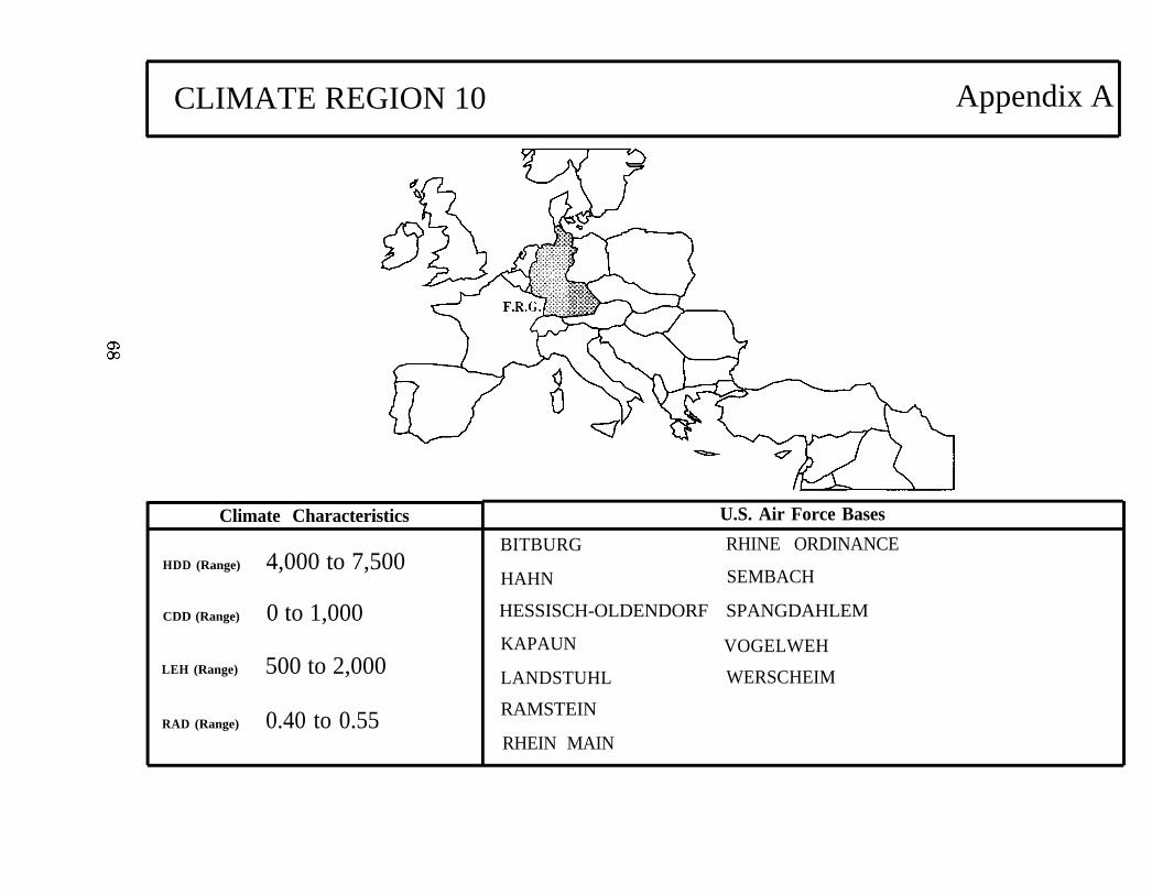
CLIMATE REGION 10 Appendix A
Climate Characteristics
HDD (Range) 4,000 to 7,500
CDD (Range) 0 to 1,000
LEH (Range) 500 to 2,000
RAD (Range) 0.40 to 0.55
U.S. Air Force Bases
BITBURG RHINE ORDINANCE
HAHN SEMBACH
HESSISCH-OLDENDORF SPANGDAHLEM
KAPAUN VOGELWEH
LANDSTUHL WERSCHEIM
RAMSTEIN
RHEIN MAIN
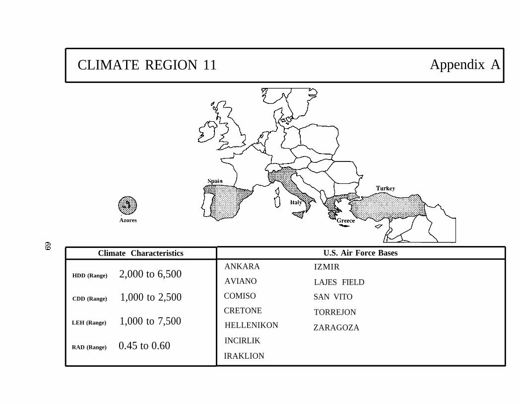
CLIMATE REGION 11 Appendix A
Azores
Climate Characteristics
HDD (Range) 2,000 to 6,500
CDD (Range) 1,000 to 2,500
LEH (Range) 1,000 to 7,500
RAD (Range) 0.45 to 0.60
ANKARA
AVIANO
COMISO
CRETONE
HELLENIKON
INCIRLIK
IRAKLION
U.S. Air Force Bases
IZMIR
LAJES FIELD
SAN VITO
TORREJON
ZARAGOZA
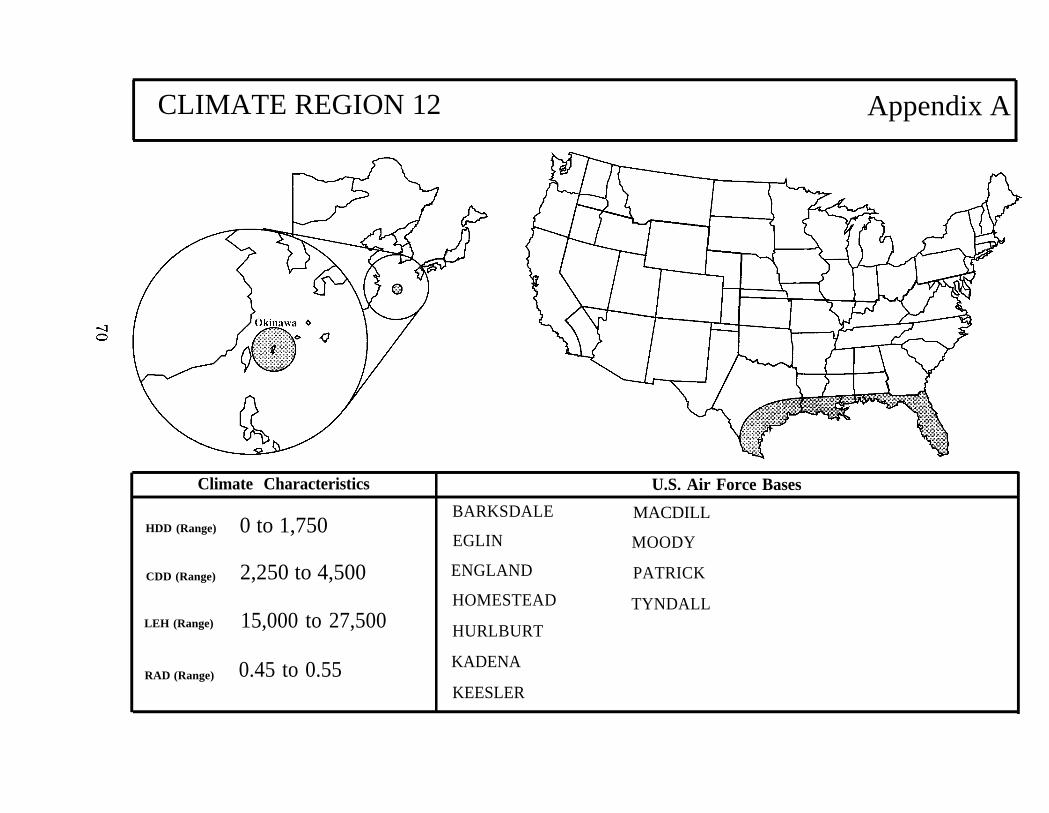
CLIMATE REGION 12 Appendix A
Climate Characteristics
HDD (Range) 0 to 1,750
CDD (Range) 2,250 to 4,500
LEH (Range) 15,000 to 27,500
0.45 to 0.55RAD (Range)
BARKSDALE
EGLIN
ENGLAND
HOMESTEAD
HURLBURT
KADENA
KEESLER
U.S. Air Force Bases
MACDILL
MOODY
PATRICK
TYNDALL
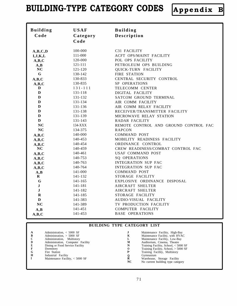
BUILDING-TYPE CATEGORY CODES Appendix B
B u i l d i n gCode
A,B,C,DI,J,K,LA,B,C
A,BNCG
A,B,CA,B,C
DDDDDDDDNCNC
A,B,CA,B,CA,B,C
NCA,B,CA,B,CA,B,CA,B,C
A,BRGJJRD
NCA,B
A,B,C
U S A FCategoryCode
100-000111-000120-000121-111121-120130-142130-833130-8351 3 1 - 1 1 1 131-118131-132131-134131-136131-138131-139131-143134-XXX134-375140-000140-453140-454140-459140-461140-753140-763140-764141-000141-132141-165141-181141-182141-185141-383141-389141-451141-453
B u i l d i n gDescr ip t ion
C31 FACILITYACFT OPS/MAINT FACILITYPOL OPS FACILITYPETROLEUM OPS BUILDINGQUICK-TURN FACILITYFIRE STATIONCENTRAL SECURITY CONTROLSP OPERATIONSTELECOMM CENTERDIGITAL FACILITYSATCOM GROUND TERMINALAIR COMM FACILITYAIR COMM RELAY FACILITYRECEIVER/TRANSMITTER FACILITYMICROWAVE RELAY STATIONRADAR FACILITYREMOTE CONTROL AND GROUND CONTROL FACRAPCONCOMMAND POSTMOBILITY READINESS FACILITYORDINANCE CONTROLCREW READINESS/COMBAT CONTROL FACUSAF COMMAND POSTSQ OPERATIONSINTEGRATION SUP FACINTEGRATION SUP FACCOMMAND POSTSTORAGE FACILITYEXPLOSIVE ORDINANCE DISPOSALAIRCRAFT SHELTERAIRCRAFT SHELTERSTORAGE FACILITYAUDIO-VISUAL FACILITYTV PRODUCTION FACILITYCOMPUTER FACILITYBASE OPERATIONS
BUILDING TYPE CATEGORY LIST
A Administration, < 5000 SF J Maintenance Facility, High-BayB Administration, > 5000 SF K Maintenance Facility, with HVACC Administration, Multistory L Maintenance Facility, Low-BayD Administration, Computer Facility M Auditorium, Cinema, TheatreE Dining or Food Service Facility N Training Facility, School, < 5000 SFF Dormitory O Training Facility, School, > 5000 SFG Fire Station Training Facility, MultistoryH Industrial Facility Q GymnasiumI Maintenance Facility, < 5000 SF R Warehouse, Storage Facility
NC No current building type category
71

BUILDING-TYPE CATEGORY CODES Appendix B
B u i l d i n gCode
U S A FCategoryCode
B u i l d i n gDescr ip t ion
D 141-454A,B 141-455NC 141-626NC 141-629NC 141-743NC 141-745NC 141-747NC 141-748
A,B,C,D 141-750NC 141-766R 141-782R 141-783
NC 141-784NC 149-962D 171-152
N,O,P 171-158N,O,P 171-211
D 171-212N,O,P 171-213N,O,P 171-214
A,B,C 171-356A,B,C 171-445
R 171-472L,R 171-473NC 171-475NC 171-476D 171-611
N,O,P 171-618A,B,C,D 171-620
D 171-621N,O,P 171-623N,O,P 171-623
NC 171-625J 171-625
N,O,P 171-712D 171-810
MOBILITY READINESS FACILITYORDINANCE CONTROLCONTROL TOWERWEATHER OBSERVATION FACILITYBASE PHOTO LABCOMBAT TARGET CTRPPIF FACILITYPASSENGER TERMINALSTECH OPERATIONS FACCHEMICAL LABORATORYAIR FREIGHT TERMINALAIR FREIGHT TERMINAL PART (ONLY)AIR PASSENGER TERMINALSTRAFFIC CONTROL TOWERCOMBAT MANEUV INSTRU FACILITYBAND CTRFLYING TRAINING CLASSROOMFLIGHT SIMULATOR TRAININGFLIGHT TRAINING UNITPHYSIOLOGICAL TRAININGHISTORICAL RESEARCH CENTERSQUAD OPS FACILITYRANGE SUPPLY AND EQUIPMENT STORAGERANGE TARGET STORAGE AND REPAIRINDOOR SMALL-ARMS RANGESMALL-ARMS MARKSMANSHIP TRAININGSCIENTIFIC FACILITYFIELD TRAINING FACILITYCOMBAT LOGISTICS SUPPORT FACILITYTECH TRAINING FACILITYTECH TRAINING LAB/SHOPAVIONICS ACADEMIC CLASSROOMSLIQ FUELS TRAINING FACHIGH-BAY TECH TRAINING FACTARGET INTELLIGENCE TRAININGRADAR BOMB-SCORE FACILITY
BUILDING TYPE CATEGORY LIST
Administration, < 5000 SFAdministration, > 5000 SFAdministration, MultistoryAdministration, Computer FacilityDining or Food Service FacilityDormitoryFire StationIndustrial FacilityMaintenance Facility, < 5000 SF
JKLMNOPQRNC
Maintenance Facility, High-BayMaintenance Facility, with HVACMaintenance Facility, Low-BayAuditorium, Cinema, TheatreTraining Facility, School, < 5000 SFTraining Facility, School, > 5000 SFTraining Facility, MultistoryGymnasiumWarehouse, Storage FacilityNo current building type category
72

BUILDING-TYPE CATEGORY CODES Appendix B
B u i l d i n gCode
U S A FCategoryCode
B u i l d i n gDescr ip t ion
N,O,P 171-813N,O,P 171-815N,O,P 171-851N,O,P 171-873N,O,P 171-875
NC 179-475I,J,K,L 200-000
I,J,K,L,R 210-000I,K,L 210-000
L 211-XXXI,J,K,L 211-000
J 211-111NC 211-111NC 211-133
I,K,L,R 211-147I,J,L 211-152
NC 211-152J 211-152
NC 211-153I,J,K,L 211-154
J 211-154I,J,K,L 211-157
J 211-159J 211-159
I,J,K 211-179NC 211-179NC 211-183NC 211-193NC 211-254NC 211-271I,J,K,L 211-271
R 212-213L,R 212-213
I,J,K,L 212-216I,J,K,L 213-XXXI,J,K,L 213-636
SAFETY EDUCATION FACILITYNCO PME CENTERLEADERSHIP DEV COMPLEXAERIAL PORTMUNITIONS LOAD-REW TRAINING FACSMALL ARMS TRAININGACFT MAINTENANCE & MGMT FACMUNI MAINTENANCE/STORAGE FACMUNITIONS MAINT FACLOW-BAY INSTRU/ELECT EQUIP MAINT SHOPMAINTENANCE COMPLEXHANGARFUEL SYSTEMS MAINT DOCKFUEL ACCESSORIES TEST FACILITYAIRCRAFT WEAPONS CAL SHELTERACFT MAINTENANCELOW-BAYMAINTENANCE HANGARNDI LABMAINTENANCE COMPLEXHIGH-BAY FACILITYGENERAL PURPOSE/NDI/ACFT ORG MAINT SHOPCORROSION CONTROL FACCORROSION CONTROL FACILITYFUEL SYSTEMS MAINT FACILITYFUEL SYST MAINT FACILITYSOUND-SUPPRESSOR SUP FACSOUND-SUPPRESSOR SUP FACCONSOLIDATED FUEL CONTROL FACILITYDEPOT INSTRUMENT OH SHOPDEPOT INSTN OVERHAUL SHOPMUNITIONS MAINT AND STORAGEMUNITIONS MAINTENANCE/STORAGEMISSILE MAINTENANCE SHOPTACTICAL MISSILE/GUIDE WEAPON MAINT SHOPMARINE MAINT SHOP
N C 214-425 VEHICLE MAINTENANCE FACILITY
BUILDING TYPE CATEGORY LIST
Administration, < 5000 SFAdministration, > 5000 SFAdministration, MultistoryAdministration, Computer FacilityDining or Food Service FacilityDormitoryFire StationIndustrial FacilityMaintenance Facility, < 5000 SF
JKLMN0
QRNC
Maintenance Facility, High-BayMaintenance Facility, with HVACMaintenance Facility, Low-BayAuditorium, Cinema, TheatreTraining Facility, School, < 5000 SFTraining Facility, School, > 5000 SFTraining Facility, MultistoryGymnasiumWarehouse, Storage FacilityNo current building type category
P
73

BUILDING-TYPE CATEGORY CODES Appendix B
B u i l d i n gCode
U S A FCategoryCode
B u i l d i n gDescr ip t ion
I,J,K,L 214-425R 214-425R 214-426R 214-428
I,J,K,L 214-467I,J,K,L 215-XXXI,J,K,L 216-642I,J,K,L 217-000NC 217-000K 217-712I,J,K,L 217-713
I,J,L,R 217-713K 217-713
I,J,K,L 217-735I,J,K,L 217-812I,J,K,L 218-712A,B,C,D 218-712L 217-762
I,J,K,L 218-852NC 218-868I,J,K,L 219-000
R 219-422I,J,K,L 219-900I,J,K,L 219-940I,J,K,L 219-943I,J,K,L 219-944
R 219-946R 219-947H 220-XXXD 310-916
NC 310-921NC 310-922NC 310-926
A,B,C,D 311-173I,J,K,L 311-174I,J,K,L 315-236
VEHICLE MAINT SHOPVEHICLE OPERATION HEATED-PARKING SHEDVEHICLE OPERATION HEATED-PARKING SHEDVEHICLE OPERATION HEATED-PARKING SHEDVEHICLE MAINT SHOPWEAPONS & MUNITIONS MAINT SHOPAMMO MAINT SHOPVEHICLE MAINT FACMAINT/STORAGE AND VEH PARKING FACAVIONICS REPAIR FACAIRCRAFT EQM POD SHOPPOD SHOP AND STORAGEHAVAIDS COMM MAINT SHOPENGINEERING TEST FACEW MAINT FACSPECIAL EQUIPMENT SHOPACFT SUP EQUIP FACHVACAIDS COMM MAINT SHOPPARACHUTE-EGRESS FACILITYPRECISION MEASUREMENT LABBCE COMPLEXSTORAGE FACILITYBCE MAINT COMPLEXBCE MAINT COMPLEXBCE MAINT SHOPBCE MAINT SHOPSTORAGE FACILITYSTORAGE FACILITYPRODUCTIONCOMPUTER SERVICE CTRBIOCOMMUNICATIONS LABOPTICAL SYS LABMICROWAVE LABACFT SYS ENG FACTEST & EVALUATION FACGUIDED WEAPON & EVAL FAC
BUILDING TYPE CATEGORY LIST
A Administration, < 5000 SFB Administration, > 5000 SF
C Administration, MultistoryD Administration, Computer FacilityE Dining or Food Service FacilityF DormitoryG Fire StationH Industrial FacilityI Maintenance Facility, < 5000 SF
JKLMNO
QRNC
Maintenance Facility, High-BayMaintenance Facility, with HVACMaintenance Facility, Low-BayAuditorium, Cinema, TheatreTraining Facility, School, < 5000 SFTraining Facility, School, > 5000 SFTraining Facility, MultistoryGymnasiumWarehouse, Storage FacilityNo current building type category
P

BUILDING-TYPE CATEGORY CODES Appendix B
B u i l d i n gCode
I,J,K,LI,J,K,LI,J,K,LI,J,K,L
RI,J,K,LNC
A,B,CNCRRRRRRR
NCNCNCNCNCJ , RRRR
NCNCNCNCNCNC
NCA,B,C
A,B,C,IA,B,CA,B,C
U S A FCategoryCode
317-311317-315317-932318-612318-612319-946319-951400-000411-135411-628422-250422-258422-264422-275441-758442-000442-257442-275442-515442-628442-750442-758442-765442-768442-769510-XXX510-001510-411510-713530-XXX540-243550-XXX610-000610-100610-111610-112
B u i l d i n gDescr ip t ion
ELECT TEC/RESEARCH LABSYS MGT ENG FACAVIONICS RESEARCH LABACFT FIRE PROT/EXPL RES FACPROPANE LAB STORAGEHAZARDOUS-MATTER EVAL FACTEST TRACK FACILITYCOMMAND POST, SUPPORTHYDRANT FUEL SYSTEM AND STORAGETOOLING SHEDOPS/MUNITIONS STORAGE FACMUNITIONS STORAGE FACILITYMUNITIONS STORAGE IGLOOSMUNITIONS PRELOAD COMPLEXDEPOT WAREHOUSERRR EQUIPMENT STORAGEBASE HAZARDOUS-MATERIAL STORAGEANCILLARY EXPLOSIVE COMPLEXMEDICAL STORAGEBASE HAZARDOUS-MATERIAL STORAGERESOURCE MANAGEMENT COMPLEXAIRCRAFT WAREHOUSE/RRR EQUIP STORAGETROOP SUBSISTENCE WAREHOUSEFORMS/PUBLICATIONS WAREHOUSEHOUSING SUPPLY/STORAGE FACILITYHOSPITAL BUILDINGDENTAL CLINICDISPENSARIESMEDICAL LOGISTICS FACILITYLABORATORIESDENTAL CLINICDISPENSARIESCONSOLIDATED SUPPORT CENTER/LOG FACACFT MAINTENANCE MGMT FACAREA DEFENSE OFFICELAW OFFICE
BUILDING TYPE CATEGORY LIST
A Administration, < 5000 SF J Maintenance Facility, High-BayB Administration, > 5000 SF K Maintenance Facility, with HVACC Administration, Multistory L Maintenance Facility, Low-BayD Administration, Computer Facility M Auditorium, Cinema, TheatreE Dining or Food Service Facility N Training Facility, School, < 5000 SFF Dormitory O Training Facility, School, > 5000 SFG Fire Station Training Facility, MultistoryH Industrial Facility Q GymnasiumI Maintenance Facility, < 5000 SF R Warehouse, Storage Facility
NC No current building type category
75
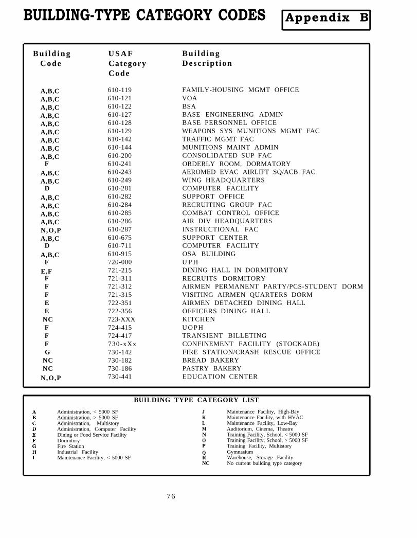
BUILDING-TYPE CATEGORY CODES Appendix B
B u i l d i n gCode
U S A FCategoryCode
B u i l d i n gDescr ip t ion
A,B,C 610-119A,B,C 610-121A,B,C 610-122A,B,C 610-127A,B,C 610-128A,B,C 610-129A,B,C 610-142A,B,C 610-144
A,B,C 610-200F 610-241
A,B,C 610-243A,B,C 610-249
D 610-281A,B,C 610-282A,B,C 610-284A,B,C 610-285A,B,C 610-286N,O,P 610-287A,B,C 610-675
D 610-711A,B,C 610-915
F 720-000E,F 721-215
F 721-311F 721-312F 721-315E 722-351E 722-356
NC 723-XXXF 724-415F 724-417F 730-xXxG 730-142
NC 730-182NC 730-186
N,O,P 730-441
FAMILY-HOUSING MGMT OFFICEVOABSABASE ENGINEERING ADMINBASE PERSONNEL OFFICEWEAPONS SYS MUNITIONS MGMT FACTRAFFIC MGMT FACMUNITIONS MAINT ADMINCONSOLIDATED SUP FACORDERLY ROOM, DORMATORYAEROMED EVAC AIRLIFT SQ/ACB FACWING HEADQUARTERSCOMPUTER FACILITYSUPPORT OFFICERECRUITING GROUP FACCOMBAT CONTROL OFFICEAIR DIV HEADQUARTERSINSTRUCTIONAL FACSUPPORT CENTERCOMPUTER FACILITYOSA BUILDINGU P HDINING HALL IN DORMITORYRECRUITS DORMITORYAIRMEN PERMANENT PARTY/PCS-STUDENT DORMVISITING AIRMEN QUARTERS DORMAIRMEN DETACHED DINING HALLOFFICERS DINING HALLKITCHENU O P HTRANSIENT BILLETINGCONFINEMENT FACILITY (STOCKADE)FIRE STATION/CRASH RESCUE OFFICEBREAD BAKERYPASTRY BAKERYEDUCATION CENTER
BUILDING TYPE CATEGORY LIST
Administration, < 5000 SFAdministration, > 5000 SFAdministration, MultistoryAdministration, Computer FacilityDining or Food Service FacilityDormitoryFire StationIndustrial FacilityMaintenance Facility, < 5000 SF
JKLMNO
QRNC
Maintenance Facility, High-BayMaintenance Facility, with HVACMaintenance Facility, Low-BayAuditorium, Cinema, TheatreTraining Facility, School, < 5000 SFTraining Facility, School, > 5000 SFTraining Facility, MultistoryGymnasiumWarehouse, Storage FacilityNo current building type category
P
76
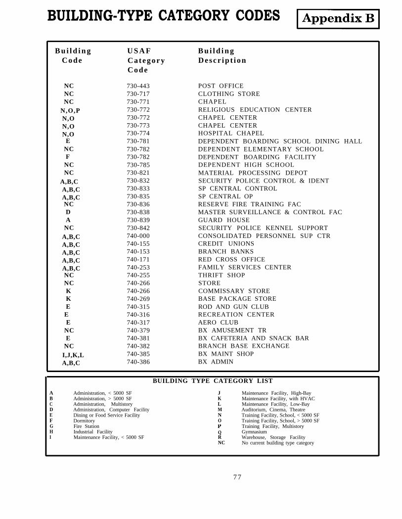
BUILDING-TYPE CATEGORY CODES
B u i l d i n gCode
U S A FCategoryCode
B u i l d i n gDescr ip t ion
NC 730-443NC 730-717NC 730-771
N,O,P 730-772N,O 730-772N,O 730-773N,O 730-774
E 730-781NC 730-782F 730-782
NC 730-785NC 730-821
A,B,C 730-832A,B,C 730-833A,B,C 730-835NC 730-836D 730-838A 730-839
NC 730-842A,B,C 740-000A,B,C 740-155A,B,C 740-153A,B,C 740-171A,B,C 740-253NC 740-255NC 740-266K 740-266K 740-269E 740-315
E 740-316E 740-317
NC 740-379E 740-381
NC 740-382I,J,K,L 740-385A,B,C 740-386
POST OFFICECLOTHING STORECHAPELRELIGIOUS EDUCATION CENTERCHAPEL CENTERCHAPEL CENTERHOSPITAL CHAPELDEPENDENT BOARDING SCHOOL DINING HALLDEPENDENT ELEMENTARY SCHOOLDEPENDENT BOARDING FACILITYDEPENDENT HIGH SCHOOLMATERIAL PROCESSING DEPOTSECURITY POLICE CONTROL & IDENTSP CENTRAL CONTROLSP CENTRAL OPRESERVE FIRE TRAINING FACMASTER SURVEILLANCE & CONTROL FACGUARD HOUSESECURITY POLICE KENNEL SUPPORTCONSOLIDATED PERSONNEL SUP CTRCREDIT UNIONSBRANCH BANKSRED CROSS OFFICEFAMILY SERVICES CENTERTHRIFT SHOPSTORECOMMISSARY STOREBASE PACKAGE STOREROD AND GUN CLUBRECREATION CENTERAERO CLUBBX AMUSEMENT TRBX CAFETERIA AND SNACK BARBRANCH BASE EXCHANGEBX MAINT SHOPBX ADMIN
BUILDING TYPE CATEGORY LIST
A Administration, < 5000 SF J Maintenance Facility, High-BayB Administration, > 5000 SF K Maintenance Facility, with HVACC Administration, Multistory L Maintenance Facility, Low-BayD Administration, Computer Facility M Auditorium, Cinema, TheatreE Dining or Food Service Facility N Training Facility, School, < 5000 SFF Dormitory O Training Facility, School, > 5000 SFG Fire Station Training Facility, MultistoryH Industrial Facility Q GymnasiumI Maintenance Facility, < 5000 SF R Warehouse, Storage Facility
NC No current building type category
77

BUILDING-TYPE CATEGORY CODES Appendix B
B u i l d i n gCode
U S A FCategoryCode
B u i l d i n gDescr ip t ion
NCKFEEEEEE
N,OLF
NCA,B,C
QA,B,CNCRM
NCN,O,PNCH
740-388 BASE EXCHANGE740-389 SERVICE OUTLET740-443 TLF740-615 CONSOLIDATED OPEN MESS740-617 OFFICERS CLUB740-618 NCO CLUB740-62X AIRMEN OPEN MESS740-732 RESTAURANT740-735 BASE RESTAURANT740-644 ARTS & CRAFTS CTR740-665 AUTO HOBBY SHOP740-666 RECREATION SITE LODGING740-668 MISCELLANEOUS RECREATION BLDG740-669 COMPOSITE RECREATION BLDG740-673 FIELD HOUSE740-674 GYMNASIUM740-675 LIBRARY740-677 INDOOR SWIMMING POOL740-733 STORAGE FACILITY740-873 BASE THEATRE740-883 YOUTH CLUB740-884 CHILD CARE CENTER760-XXX MUSEUMS AND MEMORIALS890-XXX OTHER
Q
BUILDING TYPE CATEGORY LIST
Administration, < 5000 SFAdministration, > 5000 SFAdministration, MultistoryAdministration, Computer FacilityDining or Food Service FacilityDormitoryFire StationIndustrial FacilityMaintenance Facility, < 5000 SF
JKLMNOPQRNC
Maintenance Facility, High-BayMaintenance Facility, with HVACMaintenance Facility, Low-BayAuditorium, Cinema, TheatreTraining Facility, School, < 5000 SFTraining Facility, School, > 5000 SFTraining Facility, MultistoryGymnasiumWarehouse, Storage FacilityNo current building type category
Index
This index is a cross-reference for the information in the firstthree volumes of the Passive Solar Handbook. For each entry, thevolume number is shown in parentheses, followed by the pagenumber in that volume upon which the information is located. Ifthe information is found in more than one volume, semicolons areused to separate volumes. For instance, for the entry Airmovement: (I) 26; (II) 5, information about air movement iscontained in Volume I on page 26 and in Volume II on page 5.
A-E firm: (III) 13evaluation factors: (III) 14, 19
AFRCE: (III) 6Air
A
movement: (I) 26; (II) 5temperature: (II) 5
ATR: see atriumAtrium (ATR): (I) 14, 18Automated electric lighting controls: (I) 19
Base comprehensive plan (BCP): (I) 20; (II) 1 BBCP: see base comprehensive planBuilding
climate adapted: (I) 40; (II) 9climate rejecting: (I) 40; (II) 9conventional: (II) 14elongated shape: (I) 31; (II) 6energy responsive: (I) 37multistory: (II) 25orientation: (I) 29; (II) 4, 6passive: (II) 34period of operation: (II) 10redesign: (I) 3schedule: (II) 10shape: (I) 29; (II) 4, 6target energy use: (II) 14type: (I) 32; (II) 13, 18, 21, 24type codes (USAF): (I) 32; (II) 8, 13
CBD: see Commerce Business DailyCDD: see cooling degree dayClimate: (I) 33Climate adapted building: (I) 40; (II) 9Climate regions: (I) 32; (II) 12, 18, 21, 33
special cases: (II) 23Climate rejecting building: (I) 40; (II) 9Climate variables: (I) 33
Introduction To Passive Solar Concepts 79
C
Index
Cloudiness index: see radiation and daylightCollection
daylighting: (I) 3passive solar thermal: (I) 2, 4
Commerce Business Daily (CBD): (III) 13announcement: (II) 32; (III) 1
Comprehensive planning: (III) 2Control
daylighting: (I) 3passive solar: (I) 2, 4
Conventional building: (II) 14Cooling degree day (CDD): (I) 33, 35Cooling peak demand calculation: (II) 18Core daylighting: (I) 13Credit Union: (II) 18, 30, 42
D D+S: see direct gain plus storageDaylight
planning rules: (II) 5protected zone: (II) 5site planning: (II) 6with passive solar heating: (II) 6
Daylightingatrium (ATR): (I) 14, 18concepts: (I) 1core: (I) 13monitor apertures (MON): (I) 14, 17sawtooth apertures (SAW): (I) 14, 16sidelighting: (I) 13, 14site planning: (I) 28skylights (SKY): (I) 14toplighting: (I) 13, 15windows (WIN): (I) 14
DD Form 1391: (II) 32; (III) 1, 16five year plan: (III) 2, 16Item 9: (III) 2,3,5, 16Item 10: (III) 2,3,5, 16Item 11: (III) 2,4,5, 1635% design submission: (III) 2,5
Design agent: (III) 6Design guidance: (III) 6
Tab A: (III) 6Tab B: (III) 6, 7, 16Tab C: (III) 6, 7, 17Tab D: (III) 6, 8, 17Tab E: (III) 6, 9, 17Tab F: (III) 6, 9, 17Tab G: (III) 6Tab H: (III) 6Tab I: (III) 6Tab J: (III) 6, 10, 18
80 Volume I
Index
Tab K: (III) 6Design instructions (DI’s): (III) 1, 12, 18Design manager: (III) 12, 13Detailed building energy data: (II) 17DG: see direct gainDI’s: see design instructionsDirect gain systems: (I) 5
direct gain (DG): (I) 5, 6direct gain plus storage (D+S): (I) 5, 7
Distributiondaylighting: (I) 3passive solar thermal: (I) 2
Electric lighting: (II) 39automated controls: (I) 19
Elongated shape, building: (I) 31Energy costs: (I) 43; (II) 10
cost calculation: (II) 38cost per unit of area: (II) 10determine costs: (II) 37vs. energy use: (I) 44
Energy responsive buildings: (I) 37Energy use
annual energy use calculation: (II) 23end use: (II) 15, 19, 21end use calculation: (II) 17, 38end use categories: (I) 39percent energy savings calculation: (II) 36priority: (II) 15, 19, 21vs. energy costs: (I) 44
Envelope loads: (I) 41; (II) 9vs. internal loads: (I) 43
Evaluation factors, A-E firms: (III) 14, 19Extended systems, passive heating: (I) 5
E
Five year plan: (III) 2, 16 F, G
HDD: see heating degree dayHeating degree day (HDD): (I) 33, 34Heating, ventilating, air conditioning (HVAC) systems: (II) 24
analysis: (II) 40plant size: (II) 41with night mechanical ventilation (NMV) systems: (I) 12
Hours of operation: (II) 10HQ USAF/LEE: (III) 6
H
Introduction To Passive Solar Concepts 81
Index
Humidity: (I) 26HVAC: see heating, ventilating, air conditioning systems
I, J, K Indirect gain systems: (I) 5indirect gain (IND): (I) 5, 8
IND: see indirect gain.Internal loads: (I) 41; (II) 9, 10
energy use: (II) 10occupancy characteristics: (II) 10variables: (I) 42vs. envelope loads: (I) 43
Isolated gain systems: (I) 5, 9sunspaces: (I) 5, 9
Item 9: (III) 2, 3, 5, 16Item 10: (III) 2, 3, 5, 16Item 11: (III) 2, 4, 5, 16
L Latent enthalpy hour: (I) 33, 35LEH: see latent enthalpy hour
M MAJCOMComprehensive planning: (III) 2
MON: see monitor apertureMonitor aperture (MON): (I) 14, 17Multistory buildings: (II) 25
N Natural ventilation (NVN): (I) 11; (II) 4Night mechanical ventilation (NMV): (I) 12; (II) 4NMV see night mechanical ventilationNVN: see natural ventilation
O Operable windows: (I) 12Orientation, building: (I) 29; (II) 4, 6
P, Q Passive buildingenergy use: (II) 34peak demand: (II) 34
Passive heating: (I) 4direct gain systems: (I) 5extended systems: (I) 5indirect gain systems: (I) 5
8 2 Volume I
Index
isolated gain systems: (I) 5prompt systems: (I) 5site planning: (I) 21
Passive solar systemscombinations: (II) 44components: (I) 2
PDC screen: (III) 13Peak demand: (I) 45; (II) 16, 18, 19, 21
calculation: (II) 36cooling: (I) 10; (II) 18costs: (I) 45passive building: (II) 34
People load: (II) 10Period of operation: (II) 10Project book: (III) 1, 6, 16Project description: (III) 19Project designer: (III) 6Project support data: (III) 6
Tab L: (III) 6Tab M: (III) 6, 10, 18Tab N: (III) 6, 10, 18Tab O: (III) 6, 11, 18Tab P: (III) 6, 11, 18
Prompt systems, passive heating: (I) 5Protected zone, daylighting: (I) 28
RAD: see radiation and daylightRadiation and daylight (RAD): (I) 33, 37Roof clerestory: (I) 16. see also sawtooth aperture
R
Savings-to-investment ratio (SIR): (I) 1; (II) 1SAW see sawtooth apertureSawtooth aperture (SAW): (I) 14, 16; (II) 31, 39Schedule, building: (II) 10Shading: (I) 10
coefficient: (I) 10daylighting: (I) 11
Shapebuilding: (II) 4, 6elongated: (II) 6
Sidelighting: (I) 13, 14SIR: see savings-to-investment ratioSite planning
daylighting: (I) 28passive cooling: (I) 25passive heating: (I) 21
Site selection process: (I) 20SKY: see skylights
Introduction To Passive Solar Concepts 83
S
Index
Skylights (SKY): (I) 14, 15Solar concepts: (I) 2Solar envelope: (I) 21; (II) 2
phased development: (I) 24Solar gains: (I) 26Solar PA: see solar program amountSolar program amount (Solar PA): (III) 12, 18Solar thermal concepts: (I) 1Standard Form 254: (III) 14, 15Standard Form 255: (III) 13, 14, 15Steps in comprehensive process: (II) 12
Step 1: (II) 12Step 2: (II) 13Step 3: (II) 12Step 4: (II) 16Step 5: (II) 27Step 6: (II) 27, 29Step 7: (II) 34Step 8: (II) 37Step 9: (II) 40Step 10: (III) 1
Storage, passive solar thermal: (I) 2, 4SUN: see sunspacesSunspaces (SUN): (I) 5, 9. see also isolated gain systems.
T Tab A: (III) 6Tab B: (III) 6, 7, 16Tab C: (III) 6, 7, 17Tab D: (III) 6, 8, 17Tab E: (III) 6, 9, 17Tab F: (III) 6, 9, 17Tab G: (III) 6Tab H: (III) 6Tab I: (III) 6Tab J: (III) 6, 10, 18Tab K: (III) 6Tab L: (III) 6Tab M: (III) 6, 10, 18Tab N: (III) 6, 10, 18Tab O: (III) 6, 11, 18Tab P: (III) 6, 11, 18Target building energy use: (II) 14Thirty-five percent design submission: (III) 2Toplighting: (I) 13, 15
U USAF building type codes: (II) 8
8 4 Volume I

Index
Ventilation: (II) 5 V
Warehouse: (II) 21, 32, 46Weather: (I) 33WIN: see windowsWindows (WIN): (I) 14; (II) 36
W, X, Y, Z
Introduction To Passive Solar Concepts 8 5