
Passive phase correction for stable radio frequency ...
9
Photon Netw Commun (2016) 31:327–335 DOI 10.1007/s11107-015-0519-x Passive phase correction for stable radio frequency transfer via optical fiber Shilong Pan 1 · Juan Wei 1 · Fangzheng Zhang 1 Received: 6 April 2015 / Accepted: 11 June 2015 / Published online: 26 June 2015 © Springer Science+Business Media New York 2015 Abstract The transfer of radio frequency (RF) signal via optical fiber is widely adopted in distributed antenna sys- tems and clock standard disseminating networks. To suppress the phase variation caused by fiber length fluctuation, pas- sive phase correction technique based on frequency mixing has been proved as a promising approach due to its signif- icant advantages over the traditional active compensation technique in terms of complexity, compensation speed, and compensation range. The phase correction can be done either in the transmitter or in the receiver, but it usually requires many stages of electronic mixing and auxiliary microwave signals, which not only increases the cost of the link but also degrades the quality of the transmitted signal. In addition, the effect of chromatic dispersion, polarization mode dispersion, and coherent Rayleigh noise in the optical fiber will further deteriorate the phase noise of the signal after transmission. In this paper, an analytical model for the stable RF transfer system based on passive phase correction is established, and the techniques developed in the last few years in solving the problems of the method are described. Future prospects and perspectives are also discussed. Keywords Stable RF transfer · RF delivery · Phase correction · Pre-phase distortion · Microwave photonics B Shilong Pan [email protected] 1 Key Laboratory of Radar Imaging and Microwave Photonics, Ministry of Education, Nanjing University of Aeronautics and Astronautics, Nanjing 210016, China 1 Introduction In applications such as radio astronomy, deep space network, distributed synthetic aperture radar systems, high-precision clock standard distribution, and particle accelerators, radio frequency (RF) signals are required to be transferred between different stations via optical fiber with the least phase vari- ation [1–6]. Taking advantages of low loss, high stability, large bandwidth, and immunity to electromagnetic interfer- ence, optical fiber has been proved as the best medium for long-distance RF transfer with the frequency stability sev- eral orders of magnitude better than the technique based on satellites [7, 8]. The research on disseminating RF reference signals through optical fibers can date back to 1970s for the Deep Space Network built by the National Aeronautics and Space Administration (NASA) Jet Propulsion Laboratory (JPL) [1]. After that, many optical fiber links were estab- lished for stable RF transmission. For example, a fiber link with a length of 642km was built in Italy (the Italian Link for Time and Frequency, LIFT) to transmit RF standard sig- nals from the Italian metrological institute to several Italian scientific poles with high stability [9]. Besides, optical fiber links were also built in the Atacama Large Millimeter Array (ALMA) to transfer two phase-correlated optical waves from the control center to each antenna in order to obtain stable RF references [10]. Since the environmental perturbations, such as the tem- perature changes and mechanical vibrations, would change the effective refractive index and length of optical fiber, a random phase variation will be introduced to the transmit- ted RF signal. To realize stable RF transfer, many schemes have been proposed, which can be generally classified into three categories. One method is to actively adjust the optical path by changing the length of the fiber link or the wave- length of the laser source [11–22]. The second approach is to 123
Transcript of Passive phase correction for stable radio frequency ...
Photon Netw Commun (2016) 31:327–335DOI 10.1007/s11107-015-0519-x
Passive phase correction for stable radio frequency transfervia optical fiber
Shilong Pan1 · Juan Wei1 · Fangzheng Zhang1
Received: 6 April 2015 / Accepted: 11 June 2015 / Published online: 26 June 2015© Springer Science+Business Media New York 2015
Abstract The transfer of radio frequency (RF) signal viaoptical fiber is widely adopted in distributed antenna sys-tems and clock standard disseminating networks. To suppressthe phase variation caused by fiber length fluctuation, pas-sive phase correction technique based on frequency mixinghas been proved as a promising approach due to its signif-icant advantages over the traditional active compensationtechnique in terms of complexity, compensation speed, andcompensation range. The phase correction can be done eitherin the transmitter or in the receiver, but it usually requiresmany stages of electronic mixing and auxiliary microwavesignals, which not only increases the cost of the link but alsodegrades the quality of the transmitted signal. In addition, theeffect of chromatic dispersion, polarization mode dispersion,and coherent Rayleigh noise in the optical fiber will furtherdeteriorate the phase noise of the signal after transmission.In this paper, an analytical model for the stable RF transfersystem based on passive phase correction is established, andthe techniques developed in the last few years in solving theproblems of the method are described. Future prospects andperspectives are also discussed.
Keywords Stable RF transfer · RF delivery · Phasecorrection · Pre-phase distortion · Microwave photonics
B Shilong [email protected]
1 Key Laboratory of Radar Imaging and Microwave Photonics,Ministry of Education, Nanjing University of Aeronautics andAstronautics, Nanjing 210016, China
1 Introduction
In applications such as radio astronomy, deep space network,distributed synthetic aperture radar systems, high-precisionclock standard distribution, and particle accelerators, radiofrequency (RF) signals are required to be transferred betweendifferent stations via optical fiber with the least phase vari-ation [1–6]. Taking advantages of low loss, high stability,large bandwidth, and immunity to electromagnetic interfer-ence, optical fiber has been proved as the best medium forlong-distance RF transfer with the frequency stability sev-eral orders of magnitude better than the technique based onsatellites [7,8]. The research on disseminating RF referencesignals through optical fibers can date back to 1970s for theDeep Space Network built by the National Aeronautics andSpace Administration (NASA) Jet Propulsion Laboratory(JPL) [1]. After that, many optical fiber links were estab-lished for stable RF transmission. For example, a fiber linkwith a length of 642km was built in Italy (the Italian Linkfor Time and Frequency, LIFT) to transmit RF standard sig-nals from the Italian metrological institute to several Italianscientific poles with high stability [9]. Besides, optical fiberlinks were also built in the Atacama Large Millimeter Array(ALMA) to transfer two phase-correlated optical waves fromthe control center to each antenna in order to obtain stableRF references [10].
Since the environmental perturbations, such as the tem-perature changes and mechanical vibrations, would changethe effective refractive index and length of optical fiber, arandom phase variation will be introduced to the transmit-ted RF signal. To realize stable RF transfer, many schemeshave been proposed, which can be generally classified intothree categories. One method is to actively adjust the opticalpath by changing the length of the fiber link or the wave-length of the laser source [11–22]. The second approach is to
123

328 Photon Netw Commun (2016) 31:327–335
pre-compensate the phase variation by introducing a conju-gate phase to the RF signal before transmission via a phaseshifter, a frequency shifter, or a voltage-controlled oscilla-tor (VCO) [23–35]. In practical implementations of thesemethods, the phase variations caused by the changes in thefiber link should be extracted and used to drive the tunabledevice for phase variation compensation. An active phase-locked loop (PLL) is always required. However, the PLLbandwidth is usually limited by the response speed of thetunable device, so the active methods cannot effectively dealwith the fast variations in the fiber link. Besides, due to thefinite tunable range of the compensation devices, schemes inthe first category can onlywork under the casewhere the timedelay variation is very small (usually <100ps). Recently,passive phase correction schemes based on frequency mix-ing, which can be classified as the third way to realize stableRF transfer via optical fiber, were proposed. Compared to theactive schemes applying PLLs, the passive phase correctionschemes would have a simple structure, a fast compensationspeed, and an infinite compensation range. In addition, thepassive phase correctionmethod can be achieved by both pre-phase distortion in the transmitter and post-phase correctionin the receiver.
In this paper, an analytical model for photonic stable RFtransfer system based on passive phase correction is estab-lished, which describes the principle of the method andreveals several performance limitation factors. Techniquesdeveloped in the last few years to address the issues of themethod are reviewed. The pros and cons of each scheme andthe future development of the method are discussed.
2 Principle of the passive phase correction method
The principle of the passive phase correction methodsapplying pre-phase distortion and post-phase correction isschematically shown in Fig. 1.
Mathematically, the single-frequency RF signal to betransmitted is expressed as
St(t) = cos [ω0t + ϕ0 + �ϕ0 (t)] (1)
where ω0 and ϕ0 stand for the angular frequency and theinitial phase of the RF signal, respectively. �ϕ0 representsthe random phase noise of the RF signal.
To realize phase stable transmission of the RF signal, anauxiliary signal with a half frequency of the RF signal isneeded,
Sa(t) = cos [0.5ω0t + ϕa + �ϕa (t)] (2)
where ϕa and�ϕa represent the initial phase and the randomphase noise of the auxiliary signal, respectively. The auxiliary
Fig. 1 Schematic diagram of a the pre-phase distortion scheme and bthe post-phase correction scheme
signal modulates on an optical carrier with a wavelength ofλ1 and is injected into the optical fiber. The time delay of thefiber link can be expressed as
τ =(nc + �nen + �nλ + �np
)(L + �Len)
c(3)
where nc is the effective refractive index of the optical fiberat the wavelength of the optical carrier;�nen,�nλ, and�nprepresent the variation in the refractive index induced byenvironment perturbation, wavelength drift, and polarizationrotation of the optical carrier; L stands for the physical lengthof the optical fiber link; �Len represents the variation in thephysical length introduced by environment changes; and c isthe speed of light in vacuum.
Assume that the refractive index and the physical lengthare slowly varying with time, so the forward and backwardpropagation in the fiber link can be treated to have the samedelay. If the time for one-trip transmission of the auxiliarysignal is τ1, the round-trip time delay should be 2τ1. There-fore, we can write the auxiliary signal after a round-triptransmission as
Sar(t) = cos [0.5ω0 (t − 2τ1) + ϕa + �ϕa (t − 2τ1)] (4)
In the pre-phase distortion configuration where the phasecorrection is done in the transmitter, as shown in Fig. 1a.The auxiliary signal is generated in the transmitter which ismixed with St(t) to get an up-converted signal,
St1(t) = cos [1.5ω0t + ϕ0 + �ϕ0 (t)
+ϕa + �ϕa (t)] (5)
St1(t) is sent to a second mixer, to mix with the auxiliarysignal after a round-trip transmission, as expressed in (4).The down-converted component can be written as
123
Photon Netw Commun (2016) 31:327–335 329
St2(t) = cos [ω0t + ω0τ1 + ϕ0 + �ϕ0 (t)
−�ϕa (t − 2τ1) + �ϕa (t)] (6)
It should be noted that the up-converted and down-convertedcomponents in (5) and (6) are selected by electrical band-passfilters.
As shown in (6), a conjugate phase term of ω0τ1 isintroduced to the RF signal St2(t). Then, St2(t) modu-lates another optical carrier with a wavelength of λ2 andis delivered through the same fiber link to the receiver. Ifthe transmission delay of St2(t) is τ2, the received signalis
Sr(t) = cos [ω0t + ω0 (τ1 − τ2) + ϕ0 + �ϕ0 (t − τ2)
−�ϕa (t − 2τ1 − τ2) + �ϕa (t − τ2)] (7)
As shown in (7), if τ1–τ2 equals to a constant, a stabilizedsignal with its phase independent of environment variationis obtained in the receiver.
In the post-phase correction configuration, as shown inFig. 1b, the RF signal St(t) transmits from the transmitter tothe receiver. After transmission, the signal can be rewrittenas
Str(t) = cos [ω0t − ω0τ2 + ϕ0 + �ϕ0 (t − τ2)] (8)
Then, Sa(t) in (2) is mixed with Str(t) to generate an up-converted signal
Sr2(t) = cos [1.5ω0t − ω0 + ϕ0
+�ϕ0 (t − τ2) + ϕa + �ϕa (t)](9)
Again, a second mixer is applied to mix Sr2(t) in (9) withSar(t) in (4). A down-converted component is thus obtained
Sr(t) = cos [ω0t + ω0 (τ1 − τ2) + ϕ0 + �ϕ0 (t − τ2)
−�ϕa (t − 2τ1) + �ϕa (t)] (10)
As shown in (10), as long as the difference between τ1and τ2 is a constant, the signal Sr(t) is free from the phasevariation introduced by fiber transmission.
From the above analysis, for both pre-phase distortionand post-phase correction passive phase correction scheme,the key is to ensure a constant difference in τ1 and τ2.Since the signals are transmitted in the same fiber, �nen isalmost the same for the RF and auxiliary signals, so we canobtain the residual phase variation induced by fiber transmis-sion,
�φ = ω0 (τ1 − τ2)
= ω0(nc1−nc2 + �nλ1−�nλ2+�np1 − �np2
)(L + �Len)
c(11)
In (11), the difference in the effective refractive indexnc1–nc2 is a fixed value if λ1 and λ2 are given, which canbe minimized if λ1 is close to λ2. �nλ1−�nλ1 is intro-duced because of the wavelength drifts of the two lasersources. Since the wavelength-dependent refractive indexcan be attributed to the fiber chromatic dispersion, a dis-persion compensation module or dispersion-flattened fiberscan be adopted to solve this problem. The refractive indexvariation caused by �np1–�np2 usually originates from therandom birefringence of the fiber link. Due to polarizationmode dispersion (typically 0.1 ps km−1/2 for standard single-mode fiber), the irregular rotation of the polarization statesof the two optical carriers would lead to residual phasenoise. According to the research results in [36], polariza-tion scramblers are effective tools for solving the problem.Schemes for dynamic polarization control developed in fibercommunication systems may also be utilized to remedythis.
The physical length variation in the fiber, i.e., �Len
in (11), is usually caused by temperature changes andmechanical perturbations. It has been proved that the influ-ence of temperature change on the fiber refractive index(∼7ppm/◦C) is more than one order of magnitude higherthan that on the physical fiber length (∼0.5 ppm/◦C); thus,theRFphase variation caused by the physical length variationdue to temperature changes can be neglected. Different fromthe thermal-induced slow fiber length variation, the mechan-ical vibration may cause fast change in the physical fiberlength. Pressures applied directly on the fiber also cause con-siderable RF phase variation (∼8ppm/Mpa). However, theseeffects could be weakened or even eliminated by means ofprotecting jacket or deep laying under the ground.
Since the auxiliary signal has to be transmitted in theoptical fiber link bidirectionally using the same optical car-rier, Rayleigh backscattering of the forward optical signalwill interfere with the backward optical signal, and viceversa, resulting in coherent Rayleigh noise which couldsignificantly deteriorate the phase noise of the RF signal.Wavelength conversion is a solution for this problem whenthe variation in effective refractive index caused by the chro-matic dispersion and the polarization mode dispersion isunder control.
Additionally, as can be clearly seen from (7) and (10),the phase noise of the auxiliary signal �ϕa is added to theRF signal every time when mixed with the RF signal. Thatmeans, more stages of frequencymixing bring in more noise.In addition, more signal sources are needed when the aux-iliary signals with different frequencies are used. Frequencymixingwould also bring in problems such as large conversionloss and distortion. Take into consideration the performance,cost, and complexity of the stable phase transmission system,less stages of frequency mixing and less auxiliary signals arehighly desirable.
123
330 Photon Netw Commun (2016) 31:327–335
In the last few years, great efforts were devoted to thenecessary improvements of the passive phase correctionmethod. Both the pre-phase distortion in the transmitter andpost-phase correction in the receiver were proposed anddemonstrated.
3 Post-phase correction
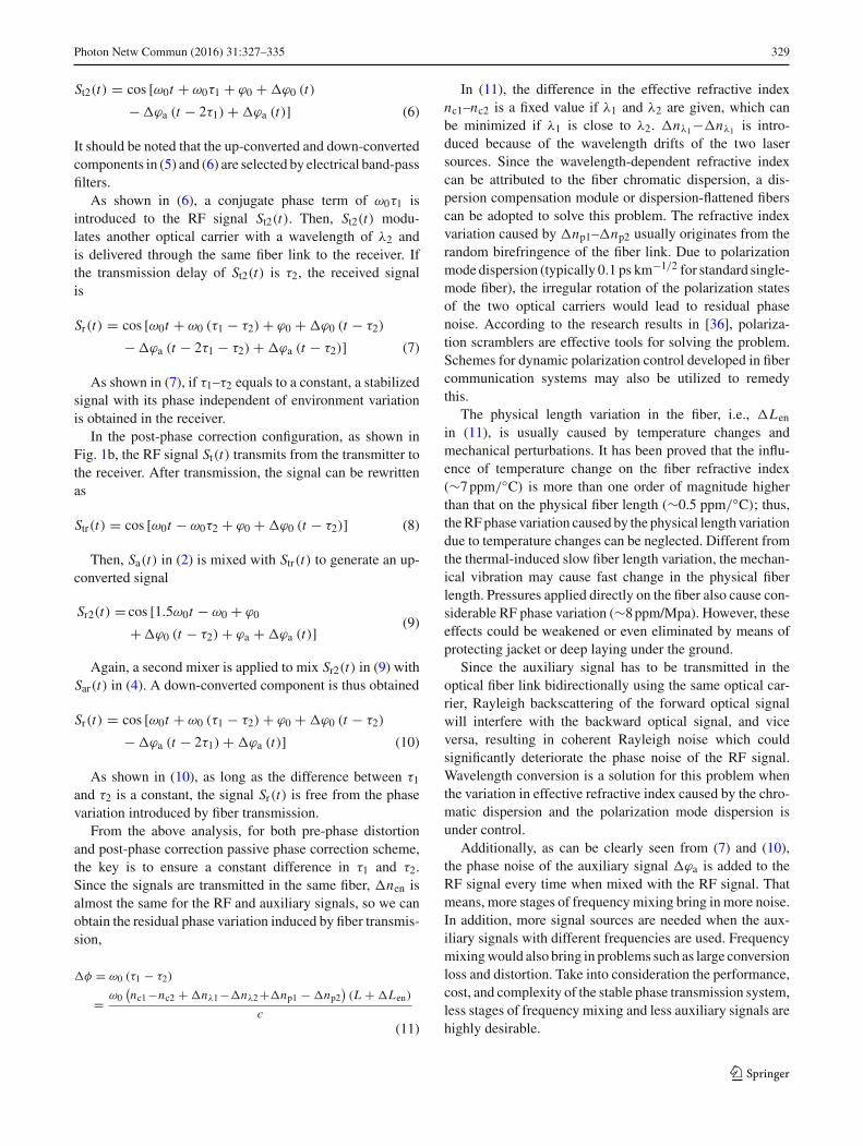
In 2013, a passive phase correction scheme for stable RFtransfer via optical fiber was reported using three stages offrequency mixing [37], in which the RF signal is transmit-ted from a remote site to the local station with post-phasecorrection. The schematic diagram is shown in Fig. 2. Anoptical carrier is directly modulated by the RF signal to betransmitted in the remote site, which is then transmitted tothe local station through a fiber link. Meanwhile, at the localstation, a local oscillator (LO) reference signal (LO1) at halffrequency of that of the RF signal modulates another opti-cal carrier and then travels a round-trip through the fiber.Considering that LO1 undergoes a doubled time delay andhas a half frequency compared to the RF signal, it has thesame phase variation caused by environmental fluctuationsas the RF signal. After the two signals are frequency mixedwith two other reference sources (LO2 and LO3), respec-tively, the obtained two down-converted signals are mixedwith each other to generate an intermediate frequency (IF)signal. Thanks to the multistage frequency mixing, the phaseterm induced by fiber transmission delay is eliminated. Thus,passive compensation of the phase error is achieved. In anexperiment, a 2.8-GHzRF signal is transmitted through a 10-km fiber link and then down-converted to a stable 10-MHzIF signal with a phase jitter of <0.05 rad.
The main drawback of this scheme is that it requires threestages of frequency mixing which results in a large conver-sion loss and distortion. In addition, the use of three auxiliarysources not only increases the cost and complexity of the sys-tem but also induce intolerable phase noise to the IF signal.
To remedy these, another passive phase correction schemeis developed,with the schematic diagramshown inFig. 3 [38].In the local station, a signal generated by a LO, having ahalf frequency of that of the RF signal to be transmitted, isused as an auxiliary signal in the remote site. This auxil-iary signal travels a round-trip through the fiber; thus, it hasthe same phase vibration caused by environmental fluctua-tions as the transmitted RF signal. Then, the transmitted RFsignal is mixed with the auxiliary signal from the LO. Theup-converted signal at the frequency that is three times of thatof the LO is selected out and then mixed with the round-triptravelled auxiliary signal. The down-converted signal has thesame frequencywith the transmitted RF signal, and the phaseterm due to fiber delay is eliminated, leading to the stabilizedRF phase transfer. In an experiment, a 6-GHz RF signal is
LO1LO2
LO3
PD1
PD2
WDM
WDM
LD1
LD2
Local Station
Remote Site
OC1
OC2
RF IN
IF OUT
f0
f0/2f2
f3
f4
EBPF1
EBPF2
SMF
Fig. 2 Diagram of the post-phase correction scheme with three aux-iliary RF sources and three stages of frequency mixing [37]. LD laserdiode, SMF single-mode fiber, WDM wavelength division multiplexer,EBPF electrical band-pass filter, LO local oscillator, OC optical circu-lator, PD photodetector
Local Station
SMF
LO
LD1
PD
Remote Site
LD2
MZM1
MZM2
EBPF2
RF IN
RF OUT
OC1
OC2
EBPF1
f0/2
f0
f0
Fig. 3 Schematic diagram of the post-phase correction scheme withone auxiliaryRF sources and two stages of frequencymixing [38].MZMMach–Zehnder modulator
123
Photon Netw Commun (2016) 31:327–335 331
Remote Site
MZM1
MZM3
PD3
LD1
LD3
WDM
Local Station
÷2
PD1
PD2
EBPF3
MZM2LD2
WDM
RF IN
RF OUT
EBPF2
EBPF1
f0
f0
f0/2
FD
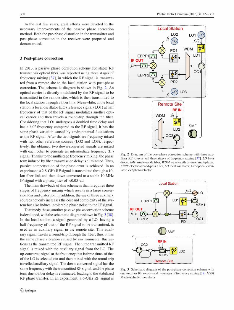
Fig. 4 Schematic diagramof the post-phase correction schemewithoutany auxiliary signal [39]. FD frequency divider
transmitted over 20-km SMFwith a root mean square (RMS)timing jitter of 1.33ps.
This scheme uses only one reference source; thus, thesystem complexity and cost are significantly reduced as com-pared to [37]. Besides, the phase noise degradation due tofrequencymixing and power amplification is alleviated, sinceonly two stages of frequency mixing are required in thescheme.
Further reduction in the number of the auxiliary RFsources can be realized by applying a frequency divider,to generate the half-frequency auxiliary signal from the RFsignal. The idea is demonstrated by Li et al. [39] with theschematic diagram shown in Fig. 4, by which passive phasecorrection without any reference source is realized. The RFsignal generated at the remote site is first transmitted to thelocal station.At the local station, the signal is divided into twobranches. One branch is passed through a frequency dividerand the obtained half-frequency signal is mixed with the RFsignal in the other branch. A signal at the frequency that is 3/2times of that of the RF signal is achieved. At the same time,the other portion of the auxiliary signal from the frequencydivider is modulated onto a second optical carrier and travelsa round-trip through the fiber. The received auxiliary signalis then mixed with the 3/2-time frequency signal, generatinga frequency component at the RF signal frequency with itsphase stabilized by the passive phase correction. In an exper-
÷2FD
Optical cable with three fibers
RF IN
fiber 1
fiber 3fiber 2
MZM
Local Station
LD
×3
OC
FT
Remote Site
PD2
PD1
RF OUT
EBPF
f0
f0
Fig. 5 Schematic diagram of the post-phase correction scheme basedon an optical cable with three fibers [41]. FT frequency tripler
iment, a 9.6-GHz signal is delivered through the optical fiberlink with a RMS timing jitter of 0.76ps.
The advantage of this scheme is that no reference signalis required, which can avoid the extra phase noise due tothe use of reference signals. Besides, wavelength conversionis performed in the remote site to avoid coherent Rayleighnoise in the optical fiber by which the bidirectional trans-mission of a RF signal on the same optical carrier results insignificantly increased phase noise [40]. The drawback is thatthe phase variation caused by chromatic dispersion would beconsiderable. In addition, more laser sources, electro-opticmodulators, and optical/electrical amplifiers are required.
To address the issue of coherent Rayleigh noise withoutusing complex wavelength conversion, the abundant fibersin the optical cable (containing many fibers in bundles) canbe taken into account considering that some of the RF signaldissemination is directly implemented in the existing opticalcommunication networks. One study is carried out by Zhanget al. [41], with the scheme shown in Fig. 5. The signal tobe transmitted with a frequency of f0 is firstly frequencydivided by two to get a signal with a frequency of 0.5 f0which modulates on an optical carrier and is transmitted tothe remote site through fiber 1 in the optical cable. In theremote site, the microwave photonic signal is divided intotwo parts by the optical coupler. One part is detected by thephotodetector (PD1), and the signal at 0.5 f0 is filtered outand further frequency tripled to generate a signal at 1.5 f0.The other part is injected into fiber 2 and transmitted to thelocal station. Since fiber 2 is directly connected to fiber 3in the local station, the microwave photonic signal transmits
123
332 Photon Netw Commun (2016) 31:327–335
back to the remote site through fiber 3 and is detected by PD2.Under the assumption that the three fibers (fibers 1–3) are inthe same bundle and they experience the same temperatureand mechanical stress, the recovered signal at 0.5 f0 has thesame phase variation accumulated along the optical fibersas the signal at 1.5 f0. When the two signals are mixed in amixer, the phase variation is eliminated and a stable signal atf0 is obtained.This scheme is compact since only one stage of frequency
mixing is used and no reference source is required. The RFsignal is free from the coherent Rayleigh noise. But thefrequency tripler would add noises to the signal, and theinconsistency of the three fibersmight result in residual phasevariation.
4 Pre-phase distortion
In addition to the post-phase correction schemes, passivephase correction can also be carried out by pre-phase distor-tion, in which the RF signal to be transmitted is introducedwith a conjugate phase that is expected to counteract exactlythe phase variation that would accumulated along the trans-mission in the optical fiber link. Then, the RF signal isstabilized when received at the receiver.
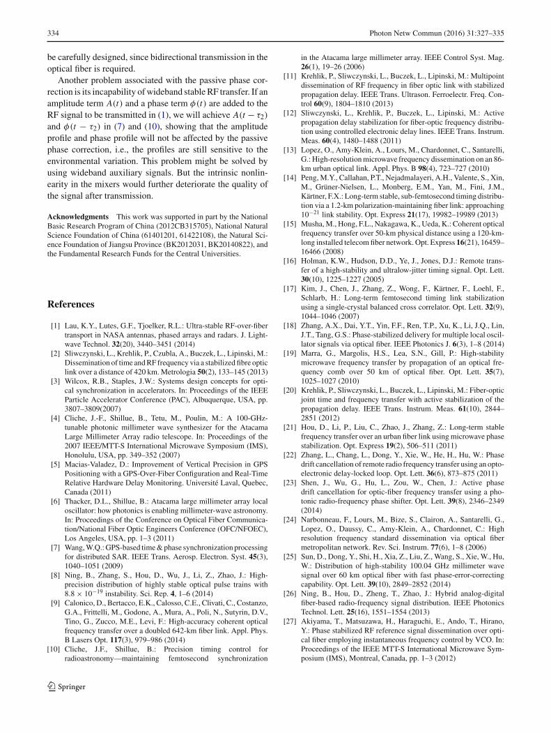
A pre-phase distortion scheme shown in Fig. 6 for stableRF transfer from the local station to the remote site is reportedin [42]. In order to transmit a RF signal with a frequency off0, an auxiliary signal (generated by LO1) with a frequencyof 0.5 f0 is transmitted a round-trip through the fiber link.After transmission, there is a phase change corresponding tothe fiber transmission delay of the auxiliary signal. The trans-mitted auxiliary signal is then mixed with another LO signal(generated by LO2) with a frequency of 1.5 f0. After mixing,the conjugate phase is brought into the generated frequencycomponent with a frequency of f0. When this component istransmitted via optical fiber and received at the remote site,the transmission-induced phase variation is eliminated. Inan experiment, a 2.42-GHz RF signal is transmitted over a30-km fiber link, and the RMS timing jitter is 1.7ps.
Local Station Remote Site
LD1
LD2
LD3
PD1 PD2
PD3
LO2
LO1
WDM
DCM
WDM
f0f0/2
3f0/2
EBPF
RF OUT
Sync
Fig. 6 Schematic diagram of the pre-phase distortion scheme usingtwo synchronized LOs [42]. DCM dispersion compensation module
Local Station Remote Site
×3
÷m
OC1 OC2
FT
FD
PD1
PD2
RF IN
LD
RF OUT
EBPF
f0/2f0
SMF
Fig. 7 Schematic diagram of the pre-phase distortion scheme with anexternal input auxiliary signal [43]
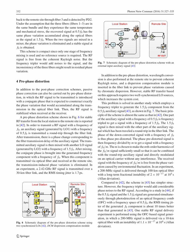
In addition to the pre-phase distortion, wavelength conver-sion is also performed at the remote site to prevent coherentRayleigh noise, and a dispersion compensation module isinserted in the fiber link to prevent phase variations causedby chromatic dispersion. However, stable RF transfer basedon this approach requires twowell-synchronizedLO sources,which increases the system cost.
This problem is solved in another study which employs afrequency tripler to generate the 1.5 f0 component from the0.5 f0 auxiliary signal [43], as shown in Fig. 7. The basic prin-ciple of the scheme is almost the same as that in [42]. One partof the auxiliary signal with a frequency of 0.5 f0 is frequencytripled to get a signal with a frequency of 1.5 f0. The 1.5 f0signal is then mixed with the other part of the auxiliary sig-nal which has been traveled a round-trip in the fiber link. Thephase of the down-converted signal with a frequency of f0is thus phase pre-distorted. The phase pre-distorted signal isthen frequency divided by m to get a signal with a frequencyof f0/m. Them is chosen tomake themth-order harmonics ofthe f0/m signal sufficiently small so that it can be combinedwith the round-trip auxiliary signal and directly modulatedon an optical carrier without any interference. The receivedsignal with the frequency of f0/m is free from the phase vari-ation caused by environmental fluctuation. In an experiment,a 200-MHz signal is delivered through 100-km optical fiberwith a long-term fractional instability of 2 × 10⁻¹⁷ at 105 s(Allan deviation).
Compared to [42], the scheme in [43] has simpler struc-ture. However, the frequency tripler would add considerablephase noises to the RF signal. According to a study in [44], ifthe 0.5 f0 signal and the 1.5 f0 signal are generated simultane-ously through photodetection of an optical frequency comb(OFC) with a frequency space of 0.5 f0, the RMS timing jit-ter of the generated f0 component is about 10 times betterthan that generated in [43]. One stable RF signal deliveryexperiment is performed using the OFC-based signal gener-ation, in which a 200-MHz signal is delivered via a 10-kmoptical fiber with an instability of 1.1×10⁻¹⁷ at 104 s (Allandeviation).
123

Photon Netw Commun (2016) 31:327–335 333
RF IN
PD2
MZM3
MZM1
OC1
Local StationFD
PD1
MZM2 OC2
RF OUTRemote Site
EBPF2EBPF1
f0
f0
SMF
Fig. 8 Schematic diagram of the pre-phase distortion scheme withoutany auxiliary signal
In [42–44], the RF signal to be transmitted is generated bytwoLO signals, but in practice theRF signal to be transmittedis generated externally. To perform passive phase correc-tion using the external input RF signal, another scheme isdevelopedwhich employs a frequency divider to generate the0.5 f0 signal and a mixer to achieve the 1.5 f0 component (bymixing the f0 signal with the generated 0.5 f0 signal) [45].The schematic diagram of the scheme is shown in Fig. 8.
For all the schemes discussed above, only passive phasecorrection based on frequency mixing is used for stablephase transmission of RF signals. Even though the passivephase correction schemes have a fast compensation speed, thephase variation caused by environmental fluctuations cannotbe compensated when the timescale of the environmentalvariation is smaller than the round-trip transmission timein the fiber link. For instance, if the optical fiber link is50km, the round-trip transmission time in the fiber link isabout 0.5ms, the phase noise above 2kHz cannot be effec-tive reduced.
To achieve both long-term stability and short-term sta-bility, a stable RF transmission scheme using passive phasecorrection together with a PLL is proposed [45], as shownin Fig. 9. Assume that the frequency of the RF signal in thelocal station is f0M, and the frequencyof a high-quality quartzoscillator is f0S. f0S is set to be very close to f0M and servesas the auxiliary signal for passive phase correction. The f0S
Local Station Remote Site
×2 P.I.Control.
SO
OC1 OC2
LD1 LD2
2DP1DP
EBPF
FD
RF IN
RF OUT
f0
f0
Fig. 9 Schematic diagram of the pre-phase distortion scheme togetherwith a PLL [45]. SO slave oscillator, P.I. control proportional integralcontroller
signal modulates on an optical carrier and is transmitted tothe local station via optical fiber. After received in the localstation, it is mixed with a frequency-doubled signal at 2 f0M.The down-converted signal with a frequency of 2 f0M– f0Sis phase pre-distorted. If f0S is exactly the same as f0M, thedown-converted signal received at the remote site will be freefrom phase variation induced by environmental fluctuation.Otherwise, if there is a phase error between f0M and f0S, thePLL will output an error signal to drive the oscillator untilf0S is exactly the same as f0M. When a 20-MHz RF signalis transmitted in a 100-km fiber, the fractional frequency sta-bility was 6 × 10⁻¹⁷ at an averaging time of 104s (Allandeviation).
5 Conclusion and discussion
In conclusion,wehave established an analyticalmodel for thestable RF transfer system based on passive phase correction,bywhich the principle of themethod and the key performancelimitations can be clearly understood. Typical techniques toaddress the issues of the method are briefly described anddiscussed.
Despite that great efforts have been devoted to the perfec-tion of the method during the past few years, there is stilla considerable room for improvement. One key issue thatmay come into view is the effect of polarization mode dis-persion (PMD). According to the experimental results shownin [36], because of different polarization states of the opticalsignals launched to the optical fiber, the microwave photonicsignals experience different time delays, which leads to con-siderable residual phase noise. The influence of the PMD canbe reduced by using polarization scramblers [36], whichmayalso be applicable for stable fiberRF transfer systembased onpassive phase correction. The configuration, however, should
123
334 Photon Netw Commun (2016) 31:327–335
be carefully designed, since bidirectional transmission in theoptical fiber is required.
Another problem associated with the passive phase cor-rection is its incapability ofwideband stable RF transfer. If anamplitude term A(t) and a phase term φ(t) are added to theRF signal to be transmitted in (1), we will achieve A(t − τ2)
and φ(t − τ2) in (7) and (10), showing that the amplitudeprofile and phase profile will not be affected by the passivephase correction, i.e., the profiles are still sensitive to theenvironmental variation. This problem might be solved byusing wideband auxiliary signals. But the intrinsic nonlin-earity in the mixers would further deteriorate the quality ofthe signal after transmission.
Acknowledgments This work was supported in part by the NationalBasic Research Program of China (2012CB315705), National NaturalScience Foundation of China (61401201, 61422108), the Natural Sci-ence Foundation of Jiangsu Province (BK2012031, BK20140822), andthe Fundamental Research Funds for the Central Universities.
References
[1] Lau, K.Y., Lutes, G.F., Tjoelker, R.L.: Ultra-stable RF-over-fibertransport in NASA antennas, phased arrays and radars. J. Light-wave Technol. 32(20), 3440–3451 (2014)
[2] Sliwczynski, L., Krehlik, P., Czubla, A., Buczek, L., Lipinski, M.:Dissemination of time andRF frequency via a stabilized fibre opticlink over a distance of 420 km.Metrologia 50(2), 133–145 (2013)
[3] Wilcox, R.B., Staples, J.W.: Systems design concepts for opti-cal synchronization in accelerators. In: Proceedings of the IEEEParticle Accelerator Conference (PAC), Albuquerque, USA, pp.3807–3809(2007)
[4] Cliche, J.-F., Shillue, B., Tetu, M., Poulin, M.: A 100-GHz-tunable photonic millimeter wave synthesizer for the AtacamaLarge Millimeter Array radio telescope. In: Proceedings of the2007 IEEE/MTT-S International Microwave Symposium (IMS),Honolulu, USA, pp. 349–352 (2007)
[5] Macias-Valadez, D.: Improvement of Vertical Precision in GPSPositioning with a GPS-Over-Fiber Configuration and Real-TimeRelative Hardware Delay Monitoring. Université Laval, Quebec,Canada (2011)
[6] Thacker, D.L., Shillue, B.: Atacama large millimeter array localoscillator: how photonics is enabling millimeter-wave astronomy.In: Proceedings of the Conference on Optical Fiber Communica-tion/National Fiber Optic Engineers Conference (OFC/NFOEC),Los Angeles, USA, pp. 1–3 (2011)
[7] Wang,W.Q.:GPS-based time&phase synchronization processingfor distributed SAR. IEEE Trans. Aerosp. Electron. Syst. 45(3),1040–1051 (2009)
[8] Ning, B., Zhang, S., Hou, D., Wu, J., Li, Z., Zhao, J.: High-precision distribution of highly stable optical pulse trains with8.8 × 10−19 instability. Sci. Rep. 4, 1–6 (2014)
[9] Calonico, D., Bertacco, E.K., Calosso, C.E., Clivati, C., Costanzo,G.A., Frittelli, M., Godone, A., Mura, A., Poli, N., Sutyrin, D.V.,Tino, G., Zucco, M.E., Levi, F.: High-accuracy coherent opticalfrequency transfer over a doubled 642-km fiber link. Appl. Phys.B Lasers Opt. 117(3), 979–986 (2014)
[10] Cliche, J.F., Shillue, B.: Precision timing control forradioastronomy—maintaining femtosecond synchronization
in the Atacama large millimeter array. IEEE Control Syst. Mag.26(1), 19–26 (2006)
[11] Krehlik, P., Sliwczynski, L., Buczek, L., Lipinski, M.: Multipointdissemination of RF frequency in fiber optic link with stabilizedpropagation delay. IEEE Trans. Ultrason. Ferroelectr. Freq. Con-trol 60(9), 1804–1810 (2013)
[12] Sliwczynski, L., Krehlik, P., Buczek, L., Lipinski, M.: Activepropagation delay stabilization for fiber-optic frequency distribu-tion using controlled electronic delay lines. IEEE Trans. Instrum.Meas. 60(4), 1480–1488 (2011)
[13] Lopez, O., Amy-Klein, A., Lours, M., Chardonnet, C., Santarelli,G.: High-resolutionmicrowave frequency dissemination on an 86-km urban optical link. Appl. Phys. B 98(4), 723–727 (2010)
[14] Peng,M.Y., Callahan, P.T., Nejadmalayeri, A.H., Valente, S., Xin,M., Grüner-Nielsen, L., Monberg, E.M., Yan, M., Fini, J.M.,Kärtner, F.X.: Long-term stable, sub-femtosecond timing distribu-tion via a 1.2-km polarization-maintaining fiber link: approaching10−21 link stability. Opt. Express 21(17), 19982–19989 (2013)
[15] Musha,M., Hong, F.L., Nakagawa, K., Ueda, K.: Coherent opticalfrequency transfer over 50-km physical distance using a 120-km-long installed telecomfiber network. Opt. Express 16(21), 16459–16466 (2008)
[16] Holman, K.W., Hudson, D.D., Ye, J., Jones, D.J.: Remote trans-fer of a high-stability and ultralow-jitter timing signal. Opt. Lett.30(10), 1225–1227 (2005)
[17] Kim, J., Chen, J., Zhang, Z., Wong, F., Kärtner, F., Loehl, F.,Schlarb, H.: Long-term femtosecond timing link stabilizationusing a single-crystal balanced cross correlator. Opt. Lett. 32(9),1044–1046 (2007)
[18] Zhang, A.X., Dai, Y.T., Yin, F.F., Ren, T.P., Xu, K., Li, J.Q., Lin,J.T., Tang, G.S.: Phase-stabilized delivery for multiple local oscil-lator signals via optical fiber. IEEE Photonics J. 6(3), 1–8 (2014)
[19] Marra, G., Margolis, H.S., Lea, S.N., Gill, P.: High-stabilitymicrowave frequency transfer by propagation of an optical fre-quency comb over 50 km of optical fiber. Opt. Lett. 35(7),1025–1027 (2010)
[20] Krehlik, P., Sliwczynski, L., Buczek, L., Lipinski, M.: Fiber-opticjoint time and frequency transfer with active stabilization of thepropagation delay. IEEE Trans. Instrum. Meas. 61(10), 2844–2851 (2012)
[21] Hou, D., Li, P., Liu, C., Zhao, J., Zhang, Z.: Long-term stablefrequency transfer over an urban fiber link using microwave phasestabilization. Opt. Express 19(2), 506–511 (2011)
[22] Zhang, L., Chang, L., Dong, Y., Xie, W., He, H., Hu, W.: Phasedrift cancellation of remote radio frequency transfer using an opto-electronic delay-locked loop. Opt. Lett. 36(6), 873–875 (2011)
[23] Shen, J., Wu, G., Hu, L., Zou, W., Chen, J.: Active phasedrift cancellation for optic-fiber frequency transfer using a pho-tonic radio-frequency phase shifter. Opt. Lett. 39(8), 2346–2349(2014)
[24] Narbonneau, F., Lours, M., Bize, S., Clairon, A., Santarelli, G.,Lopez, O., Daussy, C., Amy-Klein, A., Chardonnet, C.: Highresolution frequency standard dissemination via optical fibermetropolitan network. Rev. Sci. Instrum. 77(6), 1–8 (2006)
[25] Sun, D., Dong, Y., Shi, H., Xia, Z., Liu, Z., Wang, S., Xie, W., Hu,W.: Distribution of high-stability 100.04 GHz millimeter wavesignal over 60 km optical fiber with fast phase-error-correctingcapability. Opt. Lett. 39(10), 2849–2852 (2014)
[26] Ning, B., Hou, D., Zheng, T., Zhao, J.: Hybrid analog-digitalfiber-based radio-frequency signal distribution. IEEE PhotonicsTechnol. Lett. 25(16), 1551–1554 (2013)
[27] Akiyama, T., Matsuzawa, H., Haraguchi, E., Ando, T., Hirano,Y.: Phase stabilized RF reference signal dissemination over opti-cal fiber employing instantaneous frequency control by VCO. In:Proceedings of the IEEE MTT-S International Microwave Sym-posium (IMS), Montreal, Canada, pp. 1–3 (2012)
123

Photon Netw Commun (2016) 31:327–335 335
[28] Wang, B., Gao, C., Chen, W., Miao, J., Zhu, X., Bai, Y., Zhang,J., Feng, Y., Li, T., Wang, L.: Precise and continuous time andfrequency synchronisation at the 5 × 10⁻¹⁹ accuracy level. Sci.Rep. 2, 1–5 (2012)
[29] Fujieda,M.,Kumagai,M.,Nagano, S.: Coherentmicrowave trans-fer over a 204-km telecom fiber link by a cascaded system. IEEETrans. Ultrason. Ferroelectr. Freq. Control 57(1), 168–174 (2010)
[30] Kumagai, M., Fujieda, M., Nagano, S., Hosokawa, M.: Stableradio frequency transfer in 114 km urban optical fiber link. Opt.Lett. 34(19), 2949–2951 (2009)
[31] Ning,B.,Du, P.,Hou,D., Zhao, J.: Phase fluctuation compensationfor long-term transfer of stable radio frequency over fiber link.Opt. Express 20(27), 28447–28454 (2012)
[32] Li, Z.L., Yan, L.S., Peng, Y.L., Pan, W., Luo, B., Shao, L.Y.:Passive approach for phase fluctuation cancellation of anonymousmicrowave signal transmission. In: Proceedings of the OpticalFiber Communications Conference and Exhibition (OFC), SanFrancisco, USA, pp. 1–3 (2014)
[33] Kim, J., Cox, J.A., Chen, J., Kärtner, F.X.: Drift-free femtosecondtiming synchronization of remote optical and microwave sources.Nat. Photonics 2(12), 733–736 (2008)
[34] Kiuchi, H.: Highly stable millimeter-wave signal distribution withan optical round-trip phase stabilizer. IEEETrans.Microw.TheoryTech. 56(6), 1493–1500 (2008)
[35] Gao, C., Wang, B., Chen, W., Bai, Y., Miao, J., Zhu, X., Li, T.,Wang, L.: Fiber-based multiple-access ultrastable frequency dis-semination. Opt. Lett. 37(22), 4690–4692 (2012)
[36] Lopez, O., Amy-Klein, A., Daussy, C., Chardonnet, C., Narbon-neau, F., Lours, M., Santarelli, G.: 86-Km optical link with aresolution of 2 × 10⁻¹⁸ for RF frequency transfer. Eur. Phys.J. D 48(1), 35–41 (2008)
[37] Wu, Z., Dai, Y., Yin, F., Xu, K., Li, J., Lin, J.: Stable radio fre-quency phase delivery by rapid and endless post error cancellation.Opt. Lett. 38(7), 1098–1100 (2013)
[38] Wei, J., Zhang, F., Zhou, Y., Ben, D., Pan, S.: Stable fiber deliveryof radio-frequency signal based on passive phase correction. Opt.Lett. 39(11), 3360–3362 (2014)
[39] Li, W., Wang, W.T., Sun, W.H., Wang, W.Y., Zhu, N.H.: Stableradio-frequencyphase distribution over optical fiber by phase-driftauto-cancellation. Opt. Lett. 39(15), 4294–4296 (2014)
[40] Chang,L.,Dong,Y., Sun,D., Zhang,D.,Xie,W.,Hu,W.: Influenceand suppression of coherent Rayleigh noise in fiber-optic-basedphase-stabilized microwave-frequency transmission system. ActaOpt. Sin. 32(5), 51–56 (2012)
[41] Zhang, F., Wei, J., Pan, S.: Stable radio transfer via an optic cablewith multiple fibers based on passive phase error correction. In:Proceedings of the International Topical Meeting on MicrowavePhotonics (MWP), Sapporo, Japan, pp. 196–199 (2014)
[42] Yin, F., Zhang, A., Dai, Y., Ren, T., Xu, K., Li, J., Lin, J., Tang,G.: Phase-conjugation-based fast RF phase stabilization for fiberdelivery. Opt. Express 22(1), 878–884 (2014)
[43] Yu, L., Wang, R., Lu, L., Zhu, Y., Wu, C., Zhang, B., Wang, P.:Stable radio frequency dissemination by simple hybrid frequencymodulation scheme. Opt. Lett. 39(18), 5255–5258 (2014)
[44] Li, D., Hou, D., Hu, E., Zhao, J.: Phase conjugation frequencydissemination based on harmonics of optical comb at 10–17 insta-bility level. Opt. Lett. 39(17), 5058–5061 (2014)
[45] He, Y., Orr, B.J., Baldwin, K.G., Wouters, M.J., Luiten, A.N.,Aben, G., Warrington, R.B.: Stable radio-frequency transfer overoptical fiber by phase-conjugate frequency mixing. Opt. Express21(16), 18754–18764 (2013)
Shilong Pan received the BS and PhDdegrees in electronic engineering fromTsinghua University, Beijing, China, in2004 and 2008, respectively. From 2008 to2010, he was a “Vision 2010” PostdoctoralResearch Fellow in theMicrowave PhotonicsResearch Laboratory, University of Ottawa,Ottawa, ON, Canada. From 2010 to present,he has been with the College of Electronic
and Information Engineering, Nanjing University of Aeronautics andAstronautics, where he is currently a Full Professor and ExecutiveDirector of the Key Laboratory of Radar Imaging and Microwave Pho-tonics, Ministry of Education. His research has focused on microwavephotonics, which includes radio over fiber, photonic generation andprocessing of microwave signals, photonic integrated circuits, andphotonic-assisted measurement. He has authored or co-authored over190 papers, published in peer-reviewed journals and conference pro-ceedings.
Juan Wei received the BS degree in elec-tronic information science and technologyfrom Nanjing University of Aeronautics andAstronautics (NUAA), Nanjing, China, in2012. She is currently pursuing the PhDdegree in communication and informationsystem at NUAA. Her research interestincludes stable RF transmission over opti-cal fiber and microwave photonic signal
generation.
Fangzheng Zhang received the BS degree inoptical information science and technologyfrom Huazhong University of Science andTechnology (HUST), Wuhan, China, and thePhD degree in communication and informa-tion system from Beijing University of Postsand Telecommunications (BUPT), Beijing,China, in 2008 and 2013, respectively. Heis currently with the College of Electronic
and Information Engineering, Nanjing University of Aeronautics andAstronautics as a lecturer. He is also with the Key Laboratory of RadarImaging and Microwave Photonics, Ministry of Education. His mainresearch interests include microwave photonics, coherent optical com-munications, and all-optical signal processing.
123


