Passive Optical LAN Overview - BICSI · PDF filePassive Optical LAN Overview Bicsi Fall...
151
Passive Optical LAN Overview Bicsi Fall Conference September 28-29, 2014 Anaheim, CA
Transcript of Passive Optical LAN Overview - BICSI · PDF filePassive Optical LAN Overview Bicsi Fall...

Passive Optical LAN OverviewBicsi Fall Conference
September 28-29, 2014Anaheim, CA

Brought to you by the Association for Passive Optical LAN (APOLAN)
Founding Members:
www apolanglobal orgwww.apolanglobal.org

Passive Optical LAN: 101
Sean Kelly, RCDD, TE Connectivity

Let’s Imagine…Let’s Imagine…
Costs 40 to Costs 40 to ConsumesConsumesPromotes Promotes
inefficient seinefficient se 60% more!!60% more!!Consumes Consumes twice the twice the power!!power!!
inefficient use inefficient use of bandwidth!!of bandwidth!!
A Local Area Network that…A Local Area Network that…This describes a traditional LAN!This describes a traditional LAN!This describes a traditional LAN!This describes a traditional LAN!
An exciting new way…An exciting new way…
Passive Optical LANPassive Optical LANThe infrastructure of tomorrow available today
“A Bandwidth Efficient LAN Architecture ProvidingArchitecture Providing
Measurable CapEx & OpExSavings”g

Thoughts…
“If I’d asked customers what they t d th ld h id “ f t
Henry Ford Wisdom…
wanted, they would have said “a faster horse.”
Steve Jobs Wisdom…“Man is the creator of change in this world. As such he should be above systems and structures, and not
b di t t th ”
“There aren’t many horse and buggies on the road and most of us don’t have typewriters sitting on our desks. So why are copper networks still so widely used although they have been rendered
b l t b t ti t h l i ?” S tt F b CEO F b M di
subordinate to them.”
obsolete by next-generation technologies?” Scott Forbes, CEO Forbes Media

Key Acronyms
GPONGPON
PON POLPON vs. POL
OLT and ONT
What is Passive Optical LAN?
RevolutionaryRevolutionary
E i lEconomical
Efficient

What is Passive Optical LAN?
ITU G984.xANSI/TIA 568C
Standards based/recognized ANSI/TIA 568C
BICSI TDMM 13based/recognized
technology
Fiber Based Local Area Network
Point to Multipoint Topology

Why Passive Optical LAN?One Time
Every Year
~40-60%CapEx
~50-75%OpExReduced
CostsCable Tray, Conduit, and Pathways
Sleeving, Coring, and Fire Stopping
Construction
Costs
T h i llSinglemode
Migration
Unknown Bandwidth Capacity
Only upgrade users that need it
Technically Future Proof
Scale and R h
Easy MACs
20k /12 5 i
Can save 8-10 minutes per MAC
N 300 / 90 10 li it tiReach 20km/12.5mi No 300m / 90+10m limitations
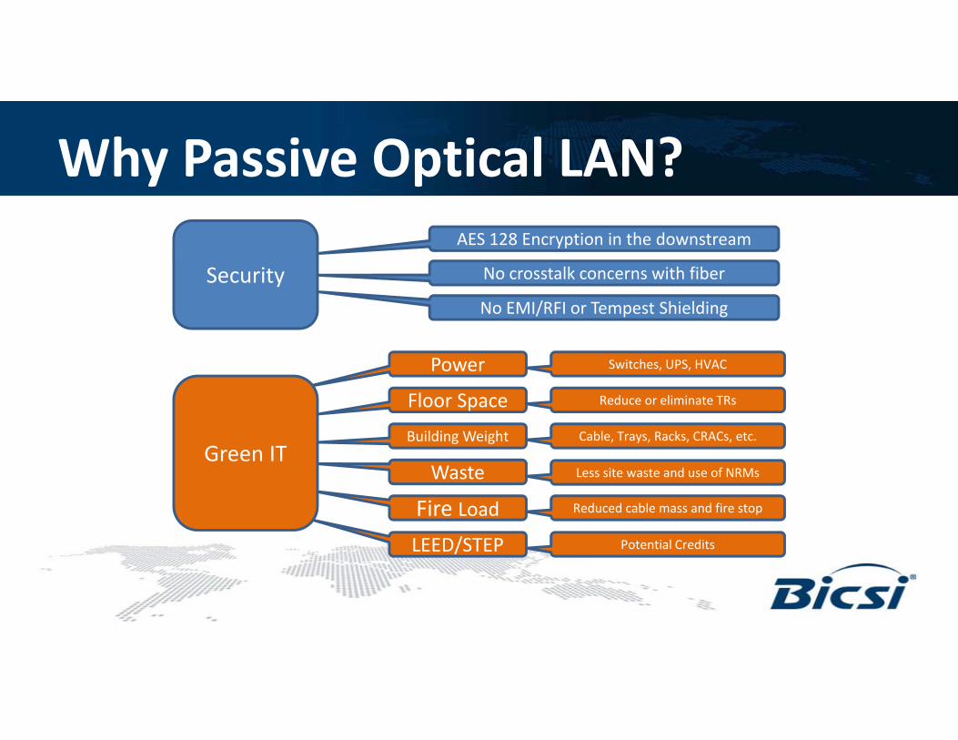
Why Passive Optical LAN?AES 128 Encryption in the downstream
No crosstalk concerns with fiberSecurity
Power Switches, UPS, HVAC
No EMI/RFI or Tempest Shielding
Security
Power
Floor Space
, ,
Reduce or eliminate TRs
Building Weight Cable, Trays, Racks, CRACs, etc.
Green ITWaste
Fire Load
Less site waste and use of NRMs
Reduced cable mass and fire stop
LEED/STEP Potential Credits
Green IT
LEED/STEP

Why Passive Optical LAN?POL electronic components are designed and
manufactured to have a service life greater than 25 years as required by carriers compared to 5 8 years
Carrier Grade years as required by carriers, compared to 5-8 years
with Enterprise grade equipment
Grade Electronics
Five 9s = 5.26 min/yr
Three 9s = 8.76 hr/yr
Five 9s (99.999) with POL vs. Three 9s (99.9) with switches
High Availability
Nearly six 9s (99.9999) of availability with POL using FSAN-B Redundancy
Availability
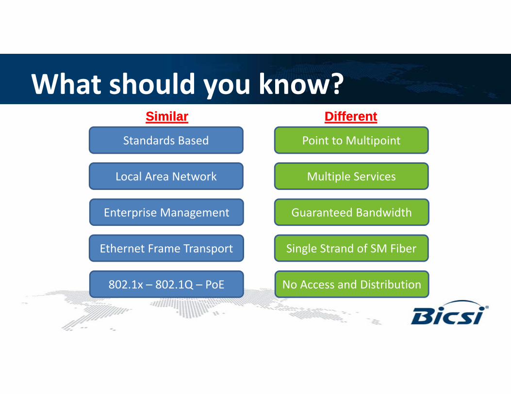
What should you know?
Standards Based Point to Multipoint
SimilarSimilar DifferentDifferent
Local Area Network Multiple Services
Enterprise Management
Eth t F T t
Guaranteed Bandwidth
Si l St d f SM FibEthernet Frame Transport
802.1x – 802.1Q – PoE
Single Strand of SM Fiber
No Access and Distribution

Where did it come from?Copper CablingCopper CablingMDUMDUSingle DwellingSingle Dwelling
• No TR/IDF• No Power• No Cooling
• No Riser Pathway• Fiber Hubs and Terminals• Minimal Pathway Required
Voice Video Data
MM
F
• No Cooling• No BBU
• No Horizontal Pathway
Cop
per
Cab
ling • No Horizontal Pathway
y q• No Power, Cooling or BBU• No TR/IDFs Required
Carrier FTTH
ONT
ONTs
Carrier FTTH

What’s the difference between a…30 Story Apartment Building 30 Story Office Buildingand a

Target POL users
Hospitals HotelsUniversities
Multi-Tenant Units (Commercial and Residential)Campuses High Occupancy Buildings
(Call Centers)( )
Sporting VenuesCasinos Government and Military
Sporting Venues
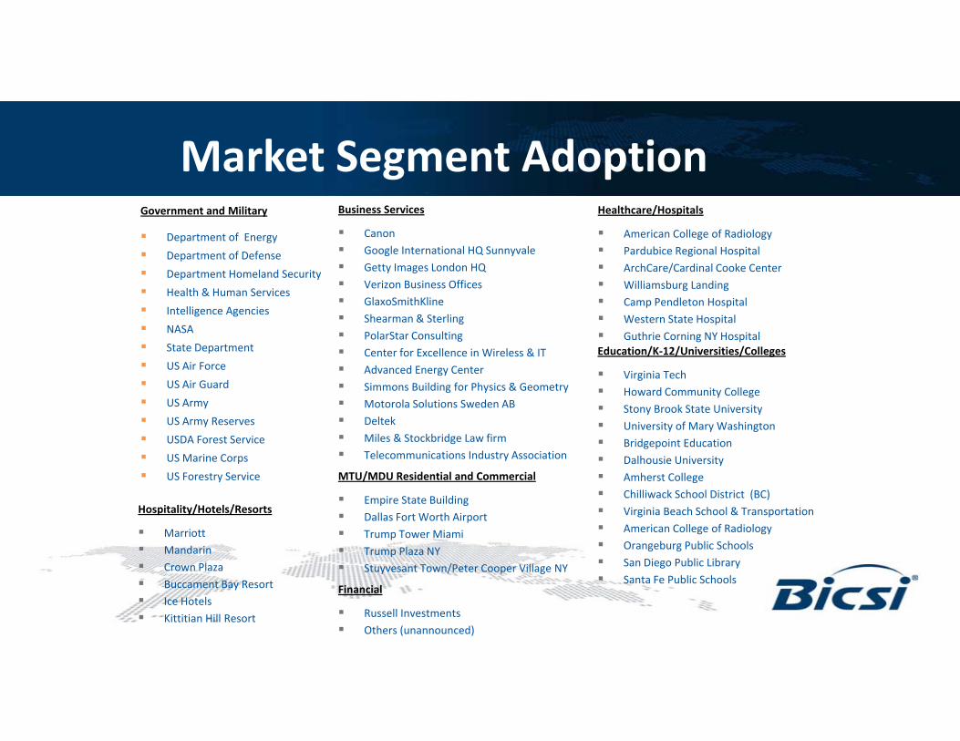
Market Segment AdoptionGovernment and Military
Department of Energy
Department of Defense
Department Homeland Security
Business Services
Canon Google International HQ Sunnyvale Getty Images London HQ
V i B i Offi
Healthcare/Hospitals
American College of Radiology Pardubice Regional Hospital ArchCare/Cardinal Cooke Center
ll b d Health & Human Services
Intelligence Agencies
NASA
State Department
US Air Force
Verizon Business Offices GlaxoSmithKline Shearman & Sterling PolarStar Consulting Center for Excellence in Wireless & IT Advanced Energy Center
Williamsburg Landing Camp Pendleton Hospital Western State Hospital Guthrie Corning NY HospitalEducation/K-12/Universities/Colleges
i i i h US Air Guard
US Army
US Army Reserves
USDA Forest Service
US Marine Corps
Advanced Energy Center Simmons Building for Physics & Geometry Motorola Solutions Sweden AB Deltek Miles & Stockbridge Law firm Telecommunications Industry Association
Virginia Tech Howard Community College Stony Brook State University University of Mary Washington Bridgepoint Education Dalhousie UniversityUS Marine Corps
US Forestry Service
y Dalhousie University Amherst College Chilliwack School District (BC) Virginia Beach School & Transportation American College of Radiology Orangeburg Public Schools
Hospitality/Hotels/Resorts
Marriott Mandarin
MTU/MDU Residential and Commercial
Empire State Building Dallas Fort Worth Airport Trump Tower Miami Trump Plaza NY g g
San Diego Public Library Santa Fe Public Schools
Mandarin Crown Plaza Buccament Bay Resort Ice Hotels Kittitian Hill Resort
Financial
Russell Investments Others (unannounced)
Trump Plaza NY Stuyvesant Town/Peter Cooper Village NY

2013 POL Implementation Global Fortune® 225 Company – Americas Headquarters Melville, NY USA
Project Overview:– Approximately 1 million sq. ft. (main building and 2 parking garages)
• Planned growth for another 200,000 sq. ft.
– 1,500 employees
• Planned growth for another 750
– Nearly 12,000 GPON Ethernet ports
Integrated Technologies over GPON:– VoIP (PCs tethered through phone)
– Security
• Access Control
• Biometrics
• Cameras (main building and parking)• Cameras (main building and parking)
• Virtual turnstiles
• Blue Phones in parking garage
– 480 WAPs
– Building automation
– Environmental controls
– IP Video content distribution
– Digital signage

San Diego Downtown Central Library
• Wireless Access Points• 9-story• 3-story domed reading
San Diego Downtown Central Library ~ modern smart and green buildingOptical LAN
• Tellabs 728GP ONT• 24-ports GbE Ethernet
e ess ccess o ts• Across library & courtyard• Free access for patrons
3 story domed reading room
• 350-seat auditorium• Technology center• Outdoor plaza and café• Coffee Bar
• Tellabs 1150/1134 OLT• Located 4th floor data room• Serves all ONTs with 18
miles
• Mainly serving WAPs • LAN services Voice over IP, data & on-line video access
• Wi-Fi throughout the library and courtyard via 36 MerakiWAPs
• 3-D Printer Connectivity
• Tellabs 709GP ONT• 4-ports GbE Ethernet• Mainly mounted under
desks
• Nearly three hundred digital devices available
• Workstations• iPads• iPad Minis• Chromebooks
• TE Single Mode Fiber• TE Passive Optical
Splitters• With Fiber Management
• Kindle• Sony eReaders
• Technology enable collaborative workspaces
• LEED Silver status

Education Vertical• K-12
• Tight budgets vs. increased demand• Space constraints and non-traditional TRs/IDFs• Aging architecture vs. modern technology
• Mondo Pads• AMX SchoolView• Smart Boards
l• Central content
• Post Secondary / Higher Education• Higher bandwidth demandg• Increased BYOD• Valuable space lost with traditional• Lost revenue and added costs
• Inefficient use of bandwidth• Inefficient use of space• Service providers profit

Hospitality Vertical• Hotels
• Industry groups driving POL advanced technology• HTNG – Hotel Technology Next Generation• HFTP – Hospitality Financial & Technology Professionals
• HITEC – Hospitality Industry Technology Exposition and Conference
• Higher port density in guest rooms and non administrative areasDi it l i• Digital signage
• Cameras• WAPs• IP card readers and locks• Four to eight data ports per guest roomFour to eight data ports per guest room
• Scalable solution with extended reach• Resort properties• Shared plot properties (Fairfield Inn, Courtyard, and Residence Inn)p p p ( y )
• Future proof cabling infrastructure

Healthcare Vertical• Assisted Living
• Patient wandering – WAP monitoring• In residence
h h• Anywhere on the property• VoIP and Data needs in residence and administration• Security and Digital Communication
• Critical Care• Higher bandwidth demand• Higher port counts in patient rooms, nurse stations, and operating rooms• Building Automation and Intelligent Structures (converged networks)
• Security • Monitoring• HVAC• Automated check-in / check out
D• Door sensors• No EMI/RFI concerns or Tempest shielding needed with fiber• Encrypted data pathways
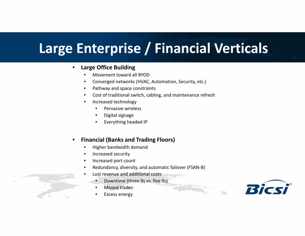
Large Enterprise / Financial Verticals• Large Office Building
• Movement toward all BYOD• Converged networks (HVAC, Automation, Security, etc.)• Pathway and space constraintsPathway and space constraints• Cost of traditional switch, cabling, and maintenance refresh• Increased technology
• Pervasive wireless• Digital signage• Everything headed IP
• Financial (Banks and Trading Floors)• Higher bandwidth demand• Higher bandwidth demand• Increased security• Increased port count• Redundancy, diversity, and automatic failover (FSAN-B)• Lost revenue and additional costsLost revenue and additional costs
• Downtime (three 9s vs. five 9s)• Missed trades• Excess energy

Call Centers, Cities, and Retail• Call Centers
• High density areas• Low bandwidth requirements
• IP Phones ~ 95Kb/s• Virtual “Dumb” terminals ~ 1Mb/s• Print/Scan/Fax ~ 500Kb/s
• Cities, Towns, Neighborhoods, and MDUs• Connect multiple buildings without distance limitations• Older buildings do not have pathways and spaces for traditional upgrades• Scalable solution for future expansionScalable solution for future expansion
• RetailDi i l i• Digital signage
• Customer Interactive Experience (pricing, web details, ordering, price compare)• Security, POS, multi-tenant service
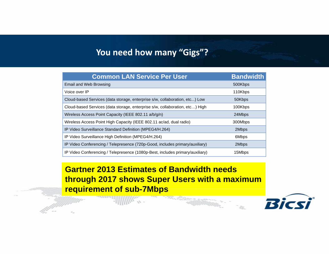
You need how many “Gigs”?
Common LAN Service Per User BandwidthEmail and Web Browsing 500Kbps
Voice over IP 110Kbps
Cloud-based Services (data storage, enterprise s/w, collaboration, etc...) Low 50Kbps
Cloud-based Services (data storage, enterprise s/w, collaboration, etc…) High 100Kbps
Wireless Access Point Capacity (IEEE 802.11 a/b/g/n) 24Mbps
Wireless Access Point High Capacity (IEEE 802.11 ac/ad, dual radio) 300Mbps
IP Video Surveillance Standard Definition (MPEG4/H.264) 2Mbps
IP Video Surveillance High Definition (MPEG4/H.264) 6Mbps
IP Video Conferencing / Telepresence (720p-Good, includes primary/auxiliary) 2Mbps
IP Video Conferencing / Telepresence (1080p-Best, includes primary/auxiliary) 15Mbps
Gartner 2013 Estimates of Bandwidth needs through 2017 shows Super Users with a maximum requirement of sub 7Mbpsrequirement of sub-7Mbps

How much bandwidth is really needed?
Optical LAN bandwidth compared to Peak bandwidth per User in 2017– Blue represents symmetrical 1 gigabit bandwidth available at every ONT port– Light Blue and Green represents Gartner Low User and High User bandwidth required 2017

Bandwidth Capacity vs. Bandwidth Traffic
HEY!!! Come check out my new 1200W stereo system. I have four 300W speakers in this thing
Hang on there, Hoss! That there is a 35W amp. You have 1200W of300W speakers in this thing.a 35W amp. You have 1200W of capacity, but only a 35W system.
300W 300W300W300W 300W 300W
35W

In traditional networks…Listen up!!! I have 10Gig OM4 Fiber in my Backbone and 10Gig Cat6 Copper in my Horizontal, so when I put in a Gig switch it won’t have any resistance and I will get a Gig to the y g gdesk and be future proof.
Backbone OM3/4 (10Gb/s) Horizontal CAT6 Cu (10Gb/s)
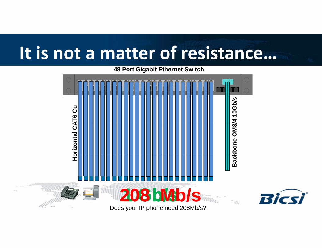
It is not a matter of resistance…48 Port Gigabit Ethernet Switch
3/4
10G
b/s
AT6
Cu
kbon
e O
M3
oriz
onta
l CA
Bac
k
Ho
1 Gb/s 1 Gb/s 1 Gb/s 1 Gb/s 208208 Mb/s Mb/s Does your IP phone need 208Mb/s?

Switch Data vs. Dynamic Bandwidth AllocationSwitch Data vs. Dynamic Bandwidth Allocation
24 Port 10/100 Ethernet Switch
100 Mb/s 100 Mb/s 100 Mb/s 100 Mb/s 100 Mb/s 100 Mb/s 100 Mb/s 100 Mb/s 100 Mb/s 100 Mb/s 100 Mb/s 100 Mb/s
100 Mb/s 100 Mb/s 100 Mb/s 100 Mb/s 100 Mb/s 100 Mb/s 100 Mb/s 100 Mb/s 100 Mb/s 100 Mb/s 100 Mb/s 100 Mb/s
E d t t h 100Mb/ C tiLet’s assume that half of the people are away from the desk
Every data port still has a 100Mb/s Connection
Most users use 0Mb/s over 98% of the workdayEvery data port still has a 100Mb/s Connection When all others are using 0Mb/s or are out of the office and a single user
has to download a large file they are limited to 100Mb/sEvery data port has a 100Mb/s Connection- A minimum of 100Mb/s- A maximum of 100Mb/s
Every data port still has a 100Mb/s Connection - A minimum of 100Mb/s- A maximum of 100Mb/s
- A minimum of 100Mb/s- A maximum of 100Mb/s
has to download a large file, they are limited to 100Mb/s.
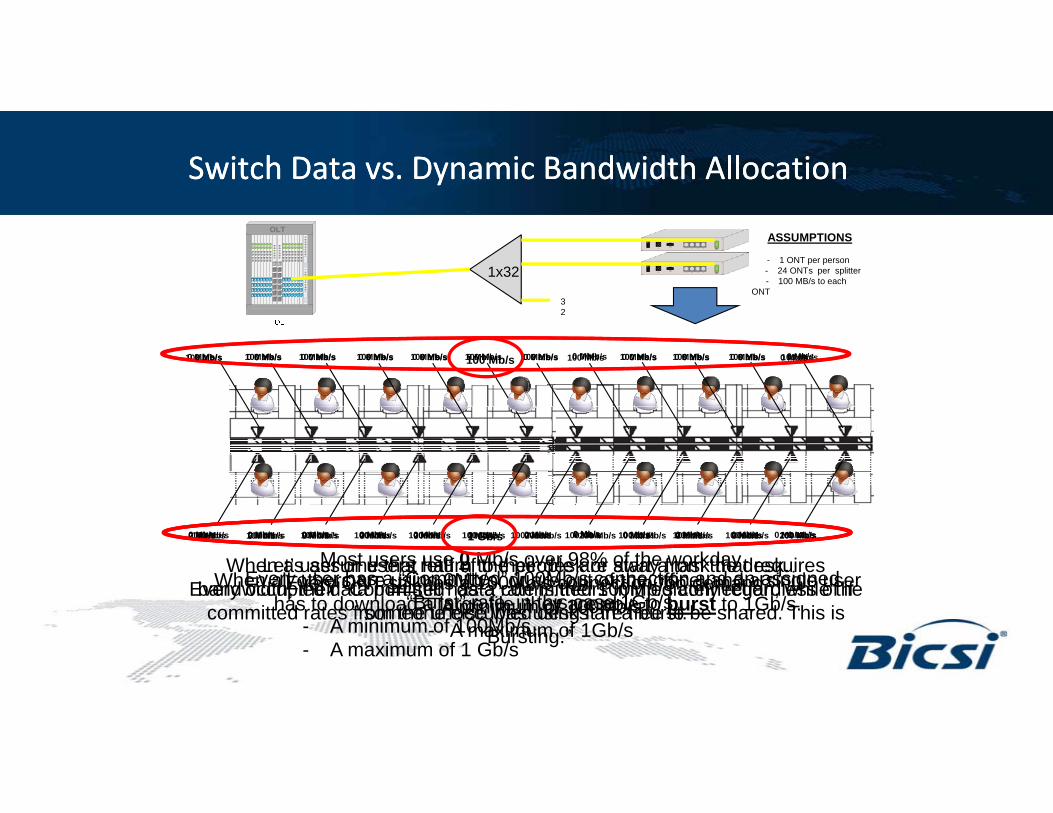
Switch Data vs. Dynamic Bandwidth AllocationSwitch Data vs. Dynamic Bandwidth Allocation
OLTASSUMPTIONS
- 1 ONT per person- 24 ONTs per splitter- 100 MB/s to each
ONT
1x32
3
100 Mb/s 100 Mb/s100 Mb/s 100 Mb/s 100 Mb/s 100 Mb/s 100 Mb/s 100 Mb/s 100 Mb/s 100 Mb/s 100 Mb/s 100 Mb/s
2
0 Mb/s 0 Mb/s 0 Mb/s 0 Mb/s 0 Mb/s 0 Mb/s 0 Mb/s 0 Mb/s 0 Mb/s 0 Mb/s0 Mb/s 0 Mb/s0 Mb/s 0 Mb/s 0 Mb/s 0 Mb/s 0 Mb/s 100 Mb/s 0 Mb/s 0 Mb/s 0 Mb/s 0 Mb/s0 Mb/s 0 Mb/s
Every user has a “Committed” 100Mb/s connection and an assigned “Burst” rate in this case 1Gb/s
Let’s assume that half of the people are away from the desk.Every occupied data port still has a committed 100Mb/s connection, while the
Most users use 0 Mb/s over 98% of the workdayEvery ONT still has a 100Mb/s connection “on demand.”
A minimum of 100Mb/s
100 Mb/s 100 Mb/s 100 Mb/s 100 Mb/s 100 Mb/s 100 Mb/s 100 Mb/s 100 Mb/s 100 Mb/s 100 Mb/s 100 Mb/s 100 Mb/s
When all others are using 0Mb/s, or are out of the office, and a single user has to download a large file they are able to burst to 1Gb/s
When a user or users return to their desk or start a task that requires bandwidth, their “Committed” data rate is theirs immediately regardless of if
200 Mb/s 200 Mb/s 200 Mb/s 200 Mb/s 200 Mb/s 200 Mb/s 200 Mb/s 200 Mb/s 200 Mb/s 200 Mb/s200 Mb/s 200 Mb/s0 Mb/s 0 Mb/s 0 Mb/s 0 Mb/s 0 Mb/s 1 Gb/s 0 Mb/s 0 Mb/s 0 Mb/s 0 Mb/s0 Mb/s 0 Mb/s0 Mb/s 0 Mb/s 0 Mb/s 0 Mb/s 0 Mb/s 0 Mb/s 0 Mb/s 0 Mb/s 0 Mb/s 0 Mb/s0 Mb/s 0 Mb/s
Burst rate, in this case 1Gb/s.- A minimum of 100Mb/s- A maximum of 1 Gb/s
committed rates from the unoccupied desks are free to be shared. This is “Bursting.”
- A minimum of 100Mb/s- A maximum of 1Gb/s
has to download a large file, they are able to burst to 1Gb/s.someone else was using it in a burst.

VLANS and Committed /Burst Rates

Traditional LAN vs. POL (GPON)
Traditional LANTraditional LAN Passive Optical LANPassive Optical LAN

On a Campus
Optical LANOptical LAN

Basic POL Schematic
PASSIVEPASSIVEPASSIVEPASSIVE(No Power Required)(No Power Required)

The Primary ComponentsOptical Line Terminal (OLTOptical Line Terminal (OLT))
• Active equipment provided by suppliers such as Tellabs, h d C
Main Equipment RoomMain Equipment Room
Zhone, and Commscope
• -48VDC Carrier Grade Chassis
• After Layer 3
U t 14 Li d• Up to 14 Line cards
• Typically 4 singlemode output ports per card
= 56 Outputs per chassis
= 1792 Work Group Terminals (1x32 splitters)= 1792 Work Group Terminals (1x32 splitters)
= 7168 Ethernet Ports (ONT has4 copper output ports)
OLT
OLT

The Primary ComponentsOOptical Splittersptical SplittersOOptical Splittersptical Splitters
Available Splits
Universal Splitter
1x2
1x4 2x4
Available Splits
Splitter Mini Plug-and Play Splitter
1x8
1x16
2x8
2x16
1U Splitter Drawer (Holds 4 Mini P-N-P Splitters)LGX Universal Splitter
1x32 2x32
Traditional 1U Rack-Mount Splitter

The Primary ComponentsONT ONT –– OOptical ptical NNetwork etwork TTerminalerminal
• Active equipment provided by suppliers such asTellabs Zhone and Commscope Work AreaWork AreaTellabs, Zhone, and Commscope.
• Located near the user or device
• Typically 4 RJ45 (10/100/1000) outputs with optional POE
Work AreaWork Area
• Up to 60W of available POE (vendor specific)
• Standard HVAC is adequate
• Optional internal or external battery back-up
ONTOptical
Network
• POTS and COAX ports available
• Establishes and maintains secure AES 128 Encryption
• Supports multiple VLANs on each portONT Terminal
ONT

ONT Placement
Desktop mountUnder-desk mount
C ili til t
Wall-mount
Ceiling tile mount
SECURE Wall Box (TE Product) Tellabs Wall Plate ONTZhone Wall Plate ONT

Distance and LossOLT Output
= +3dBmONT Range =
-12.5dBm to -26dBm
Minimum of 15.5dB
l i d!loss required!
ONT
Cat6
1x32
Passive Equipment (S litt )
12.5mi / 20km Up to100m(Solid Conductor Cable)
(Splitter)

Type B (FSAN-B) RedundancyIf any interruption is detected on the primary path (OLT to ONT),the OLT will switch to the redundant path instantaneously.
Category 6
Primary Path
ONT
2x32
OLT h i i “C i G d ” i th t
Redundant Path
OLT chassis is “Carrier Grade” meaning that it is designed to be in service for 25+ years with 100 possible.
Type B Redundancy = Nearly Six 9sType B Redundancy = Nearly Six 9s

Example Layout of Type B (FSAN-B) Redundancy

IP/Ethernet Protocol Support
Network Integration
Multiple 1G and 10G Ethernet Uplinks
IEEE 802.3ad Link Aggregation Control Protocol (LACP)
Service Delivery
802.1p: Class of Service
IP differentiated services code point (DSCP)
Quality of Service: Per-VLAN Per-Port
Monitoring / Management
SNMP v1, v2, v3
CLI Console Port
Remote Monitoring (RMON) software agentIEEE 802.1Q VLAN Encapsulation
IEEE 802.1w Rapid Spanning Tree (RSTP)
IEEE 802.1s Multiple Spanning Tree (MSTP)
Virtual Router-to-Router Redundancy (VRRP)
IPv4 / IPv6
Quality of Service: Per VLAN, Per Port, Per-Service queuing / scheduling *
Sophisticated QoS and Traffic Management
Eight Queues per VLAN
Policing, Scheduling, Shaping per Queue
Congestion and Flow Control
Remote Monitoring (RMON) software agent
RMON I & II
Enhanced SNMP MIB support
RFC 1213-MIB (MIB II)
Extended MIB supportIPv4 / IPv6
IGMPv2 / IGMPv3
Network Access Control (NAC)
IEEE 802.1x (Port-based Authentication)
Dynamic Host Control Protocol (DHCP)
Congestion and Flow Control
Hardware Based ACLs: L2, L3, L4
Hardware Based Multicast Management
IEEE 802.3af, 802.3at (PoE)
Link Layer Discovery Protocol (LLDP)
Network Timing Protocol (NTP)
RADIUS based authentication
SSH v1, v2
VMWare Support for EMS
OLT SysLog support (2014)DHCP Snooping and Option 82 insertion
Port Security, Sticky MACs
RFC-2267 (Denial of Service)
Traffic Storm Control
Bridge Protocol Data Unit (BPDU) Guard
OLT SysLog support (2014)
Y.1371 (2014)
802.1ag Fault Detection (2014)
Bridge Protocol Data Unit (BPDU) Guard
This represents a partial list of supported IEEE and IP/Ethernet protocols

Savings
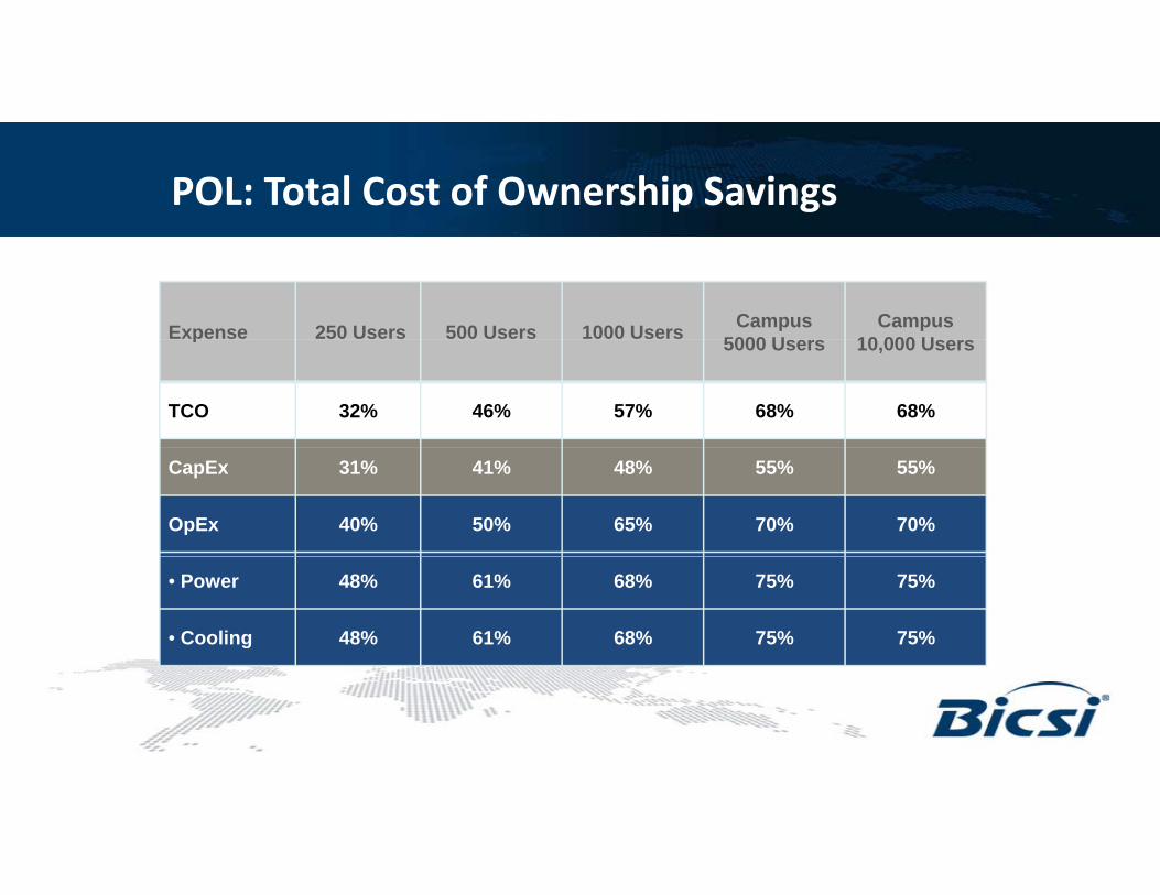
POL: Total Cost of Ownership Savings
Expense 250 Users 500 Users 1000 Users Campus 5000 U
Campus 10 000 Up 5000 Users 10,000 Users
TCO 32% 46% 57% 68% 68%
CapEx 31% 41% 48% 55% 55%
OpEx 40% 50% 65% 70% 70%
• Power 48% 61% 68% 75% 75%
• Cooling 48% 61% 68% 75% 75%

POL: Power Consumption Comparison
Price per kw hour $0.082 W/HR Annual $Total POL Budget 14,050 $10,081 Total Traditional Budget 37,171 $26,670 Difference (23,121) ($16,589)
Regional Medical Center Regional Medical Center 4000 drops4000 drops Total Savings Percentage -62.20%
Traditional LAN Passive Optical LAN
Main Distribution Frame Main Distribution Frame
Description Quantity Rated Power Total Power Notes Description Quantity Rated Power Total Power NotesCisco WS-C3750X-48P-S(715W) 7 134 937 AXS1800 2 516 1,032 2-SW, 2-SYS, 8-PONUPS 1 937 187 UPS overhead UPS 1 1,032 206 UPS overhead
4000 drops4000 drops
HVAC 1 1,125 1,350 Draw to cool UPS & Cisco *1.2 HVAC 1 1,238 1,486 Draw to cool UPS & AXS *1.2Total 2,474 Total 2,724
Intermediate Distribution Frames Intermediate Distribution Frames
Description Quantity Rated Power Total Power Notes Description Quantity Rated Power Total Power NotesCisco WS-C3750X-48P-S(715W) 96 134 12,854 N/A N/A N/A N/AUPS 1 12,854 2,571 UPS overheadHVAC 1 15,425 18,510 Draw to cool UPS & Cisco *1.2Total 33,936 Total 0
Desktop/Work Area Desktop/Work Area
Description Quantity Rated Power Total Power Notes Description Quantity Rated Power Total Power NotesN/A WT21004 1,255 9 11,295 Admin areas
Total 0 Total 11,295
Power over Ethernet Power over Ethernet
Description Quantity Attenuation Total Power Notes Description Quantity Attenuation Total Power NotesCopper drops 1,463 Copper drops 1,463 Average length of drop 200 Average length of drop 8 Total feet 292,600 0.0026 761 Total loss via PoE Total feet 11,704 0.0026 30 Total loss via PoETotal 761 Total 30

Potential* LEED Credits
• Energy and Atmosphere Credit 1 (1-3 pts).
• Reduction in TRs, HVAC equipment, switch equipment, UPS, lighting and other energy needs.
• The PON system helps the overall efficiency of the energy systems.
• Innovation in Design Credit 1 (1-4 pts).
• The PON system utilizes less equipment, resulting in less raw materials, l b l i d d d i f i l iless garbage, less transportation and reduced time for implementation and commissioning.
• In addition, utilizing a fiber system ensures the life of the system extends beyond the life of a conventional “switched” system.
*not guaranteed or implied

“Eco-Friendly”
• Reduced Power Requirements• Savings between 40% to 60%
• Reduced HVAC Requirement• Reduced HVAC Requirement• A Fortune 500 company saved about
$450K on the Power distribution network (HVAC, backup etc) for a building project with 2000 Ethernet portsp
• Reduction in Non-renewable materials
• Reduction of up to 8000 pounds of plastic and copper versus a Cat 6 install for
Reduction in non-renewable materials
Green Benefits Reduction in power consumption
Ceiling space and fire load savings
and copper versus a Cat 6 install for building of 4000 Ethernet ports
• Floor Space Savings• Traditional layer-2 solutions are bound by
the 300ft Ethernet limitation Reduction in cabling costsFloor space savings
the 300ft Ethernet limitation
• Fire Load Savings• Savings in Sprinkler Systems• Fire Load and ceiling space savings

Questions?
49
TIA Compliant PassiveTIA Compliant Passive Optical LAN Design and p g
Testing

Agenda
• TIA Standards regarding Passive Optical LANs
C P i O i l LAN C fi i• Common Passive Optical LAN Configurations
• Other Design Considerations
• Test & Certification of Passive Optical LANs• Test & Certification of Passive Optical LANs

TIA Standards Applicable to Passive Optical LAN Designp g
• TIA establishes and maintains standards for the premise wiring industry• Applicable standards include:pp
– ANSI/TIA-568-C.0, Generic Telecommunications Cabling for Customer Premises
– ANSI/TIA-568-C.1, Commercial Building Telecommunications Cabling Standard
– ANSI/TIA-568-C.2, Commercial Building Telecommunications Cabling Standard; Part 2: Balanced Twisted Pair Cabling Components
– ANSI/TIA-568-C.3, Optical Fiber Cabling Components Standard
– TIA-569-C, Commercial Building Standard for Telecommunications Pathways and Spaces
– ANSI/TIA/EIA-606-B, Administration Standard for Commercial Telecommunications
– ANSI-J-STD-607-A, Commercial Building Grounding (Earthing) AND Bonding Requirements , g g ( g) g qfor Telecommunications
– ANSI/TIA-578-B, Customer Owned Outside Plant Telecommunications Infrastructure Standard
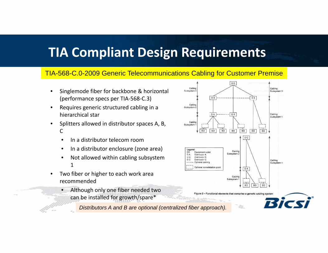
TIA Compliant Design RequirementsTIA-568-C.0-2009 Generic Telecommunications Cabling for Customer Premise
• Singlemode fiber for backbone & horizontal (performance specs per TIA-568-C.3)
• Requires generic structured cabling in a hierarchical star
• Splitters allowed in distributor spaces A, B, p pC
• In a distributor telecom room
• In a distributor enclosure (zone area)
• Not allowed within cabling subsystem• Not allowed within cabling subsystem 1
• Two fiber or higher to each work area recommended
Al h h l fib d d• Although only one fiber needed two can be installed for growth/spare*
Distributors A and B are optional (centralized fiber approach).
Benefits of Singlemode Fiber for the LAN
Superior Performance Easier Installation Easier Installation Pulling Tension Highly SecureHighly Secure Easier to Upgrade Non-flammable Environmentally FriendlyMuch smaller

TIA Performance Criteria
Singlemode fiber
TIA-568-C.3 Optical Fiber Cabling Components Standard
Connector Performance• Attenuation
–Indoor/Outdoor, Outdoor < .5 dB/km
–Indoor < 1.0 dB/km
• Attenuation (insertion loss)– Fiber connectors < .75 dB
– Fiber splices < .3 dB• Inside plant
–Pull strength 50 lbf min
–Bend radius (<= 4 fibers 1 inch, 2 inches
Fiber splices < .3 dB
• Return Loss– 26 dB, 55 dB analog video
• Other temperature humidity impactBend radius ( 4 fibers 1 inch, 2 inches under load) (> 4 fibers 10x outer dia., 20x outer dia. under load)
• Other: temperature, humidity, impact, coupling strength, ….
Enhanced products offered from manufacturers today -• Singlemode bend insensitive fiber:
• 5mm bend radius (G.657.B3) , indoor/outdoor attenuation < .4 dB/km • Easy installable mechanical connectivity:
• Connectors IL < .2-.3 dB typical & RL >55-60 dB; Splices < .1 dB typical
TIA Passive Optical LAN support added August 2012g
Splitter attenuation included in the Channel measurements
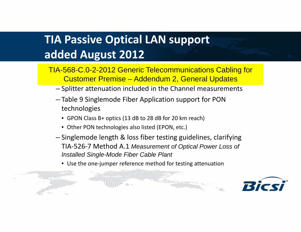
TIA-568-C.0-2-2012 Generic Telecommunications Cabling for Customer Premise – Addendum 2, General Updates
– Splitter attenuation included in the Channel measurements
– Table 9 Singlemode Fiber Application support for PON technologies
G ON Cl i (13 d 28 d f 20 k h)• GPON Class B+ optics (13 dB to 28 dB for 20 km reach)
• Other PON technologies also listed (EPON, etc.)
– Singlemode length & loss fiber testing guidelines, clarifying TIA 526 7 M th d A 1 M t f O ti l P L fTIA-526-7 Method A.1 Measurement of Optical Power Loss of Installed Single-Mode Fiber Cable Plant• Use the one-jumper reference method for testing attenuation

Copper-based LAN• Active Ethernet switches for LAN core,
aggregation and access functions
Passive Optical LAN• Passive optical network (PON)
o Optical Line Terminal (OLT)i l di ib i k• Cable infrastructure per service
o CATxo Coaxo Some Multi-mode Fiber (MMF)
o Optical distribution networko Optical Network terminations (ONT)
• Single mode fiber converges all building ICT services over single infrastructure
Local
OLT
CentralizedProvisioning &Management
LocalProvisioning &
Management
Campus Aggregation
Over20km/12miDistance
PassiveNetwork
DistanceLimited –
MMF – 550mCopper – 100m
Building Aggregation
Communication Closetpp
End User
wirelessbuilding
automation
security

Common POLS Configurations – A & B
SPLITTERS IN
TR/Closet
Cat x cordsBackbone &
ONT1Optical splitter(s)
Cabling Subsystem 1TR/Closet
Telecom Room (TR)/Closet
PC, VoIP phone, printer,
WAP, etc.
HorizontalCross-connect
SPLITTERSone
ONT
ONT
Fiber patchcords
2Optical splitter(s)
Wall outlet
Backbone
Floors 1-n
Telecom EnclosureSPLITTERS
IN ZONE DISTRIBUTO
RBack
bo
Optical Network
Terminals (ONT)
Fiber patch panels –
OLT to Riser/
backbone
Optical LineConfiguration 2 – Zone Distributor AOLT
BackboneCross-connect Configuration 1 – TR Distributor A
Optical Line Terminal (OLT)
Equip.Room (ER)
MC
58

Infrastructure Fundamentals
• Simplex Singlemode fiber
• Polarity not a concern for Tx/Rx signals
• Multimode cannot support the bandwidth & reachMultimode cannot support the bandwidth & reach
• Multimode does not support both TX/RX on one fiber
• Connector type
• Typically all simplex SC/APC type• Typically all simplex SC/APC type
• Some exceptions (check with equipment vendors)
• OLT GPON ports (SC/UPC), OLT SFP/XFP uplinks (LC/UPC)
• Heavy duty ladder rack not required J-• Heavy duty ladder rack not required
• Fiber is light weight & tiny compared to copper
• Longevity, reliability of the fiber plant
• Choose quality splitters connectors
Jhook
• Choose quality splitters, connectors
• Choose vendor who offers an extended warranty

Building Owner’s Architectural Considerations
• New building construction/architecture– Freedom offered by distance of singlemode fibery g– Less space and cabling materials required– Less in cabling support systems (ladder rack)– Less fire load– Less distributor/telecom room spacing (sqft) required
• Less floor distributor HVAC, UPS, copper patch panels, support systems, etc.
– Consolidation of systems supporting converged services– Consolidation of systems supporting converged services– Consolidation of multiple cabling infrastructures all over
one singlemode fiber

GREEN Buildings
• Passive Optical LANs lend easily to Green & Sustainability initiatives– Reduction of electronics power consumption/per Ethernet port
– Reduced physical cabling materials & new construction support systemsReduced physical cabling materials & new construction support systems
– Longevity of the fiber infrastructure
– Converged services support for voice, video, data, security, WiFi, BAS …
• LEED® - Leadership in Energy and Environmental Design (LEED®) rating system by the U.S. Green Building Council (USGBC)
• STEP - Sustainable Technology Environments Program– Ratings plan that will bring sustainability to technology systems
TIA TR 42 10 Standard for Sustainable Information Communications– TIA TR-42.10 Standard for Sustainable Information Communications Technology (TR-42 TIA standard development in process)
– Key goals of STEP include:
– Minimize energy, Reduce waste, Optimizing infrastructure d d l b l d ldesign, Provide scalability, & Reduce construction materials

Other Design Considerations
• PON Equipment Vendor Options:
– Some ONT’s support Power over Ethernet (WAPs, VoIP ppphones,…) IEEE802.3af, at
– ONT interfaces support copper horizontal distances (100 m)
– Redundancy options for fiber facility and/or addedRedundancy options for fiber facility and/or added equipment redundancy
– Options for remote powering &/or battery reserve at ONT
P i i f t t h i• Passive infrastructure choices:
– Splitters
– Interconnect vs. Cross-connect
– Fiber connectivity
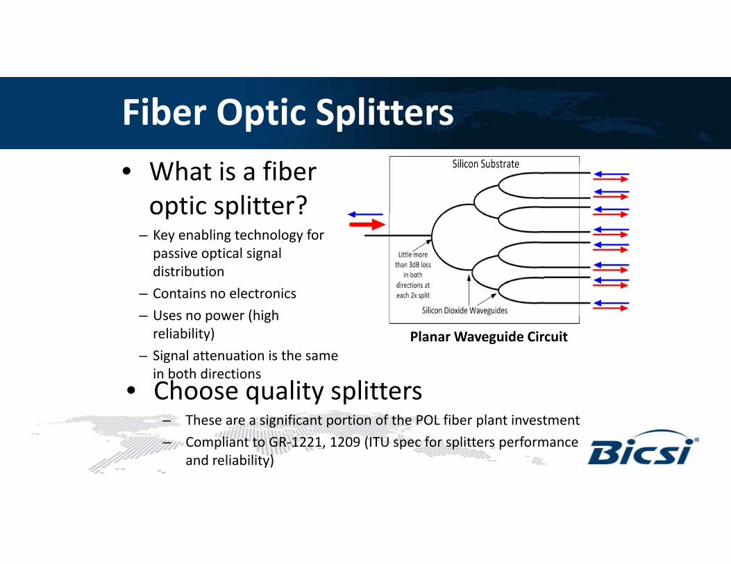
Fiber Optic Splitters• What is a fiber
optic splitter?optic splitter?– Key enabling technology for
passive optical signal distribution
Planar Waveguide Circuit
– Contains no electronics
– Uses no power (high reliability)
Si l i i h
• Choose quality splittersThese are a significant portion of the POL fiber plant investment
– Signal attenuation is the same in both directions
– These are a significant portion of the POL fiber plant investment
– Compliant to GR-1221, 1209 (ITU spec for splitters performance and reliability)

Fiber Optic SplittersOOptical Splittersptical SplittersOOptical Splittersptical Splitters
Available Splits
Universal Splitter
1x2
1x4 2x4
Available Splits
Splitter Mini Plug-and Play Splitter
1x8
1x162x8
1U Splitter Drawer (Holds 4 Mini P-N-P Splitters)LGX Universal Splitter
1x32 2x16
Traditional 1U Rack-Mount Splitter
2x32

Interconnect vs. Cross-connectConsiderations–Ease of test and MACs w/o
unplugging horizontal or splitter legs
I) Faceplate Module Interconnect Solution Fiber from backbone to
splitter input on front
III) Splitter Module Cross-connect Solution
1x32–Are all splitter outputs goingto be used?
–Adds 1 connector pair (IL)where implemented
Fiber from backbone to splitter input on front
Horizontal
3-slot wide 1x32
II) Pigtail Splitter Module Interconnect Solution
Standard simplex fiber patch
1x32 way splitter module
Horizontal cabling plugs into front splitter output ports
1x32 way splitter module
Attached input(s) and output legs
Interconnect Solution
32 pre-terminated
output Added adapter plate and fiber patch
Horizontal cabling plugs into back of adapter plate
pcord
32 port adapter plate
Horizontal cabling plugs into adapter
output legs
Output legs of the splitter plug into front
Added adapter plate and fiber patch cords facilitate full cross-connect/ patching between splitter and horizontalAn interconnect choice
is the most dense and cost-effective solution.
back of adapter plate
pplate
Added adapter plates between splitter and horizontal cabling complete this interconnect solution.
plug into front of adapter plate
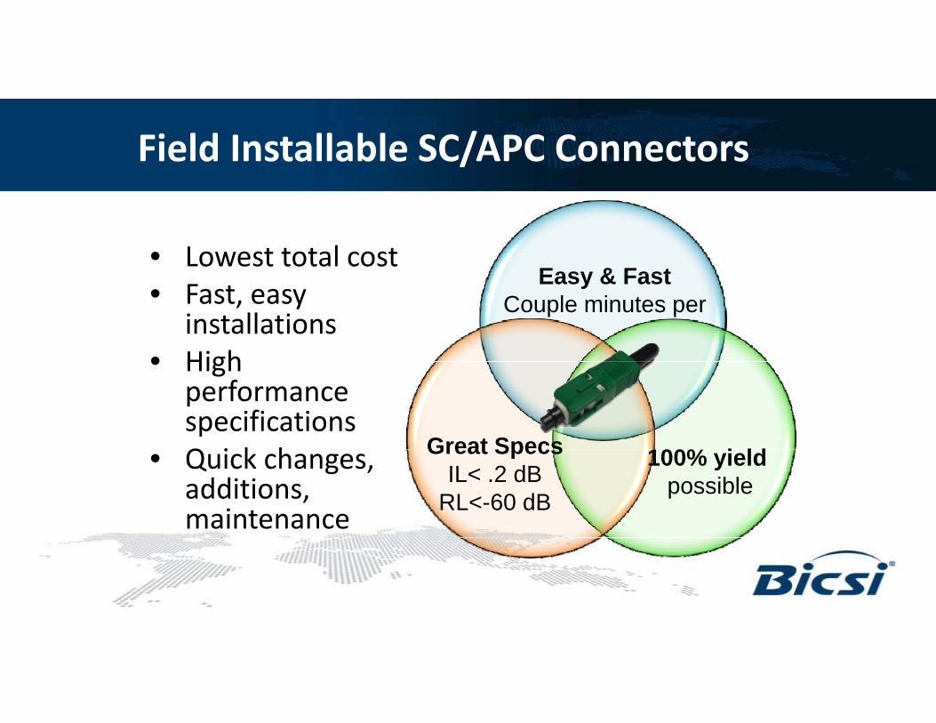
Field Installable SC/APC Connectors
• Lowest total costEasy & Fast• Fast, easy
installations• High
Easy & FastCouple minutes per
• High performance specificationsQ i k h Great Specs 100% i ld• Quick changes, additions, maintenance
Great SpecsIL< .2 dB
RL<-60 dB
100% yield possible

ANSI/TIA-568-C.0-2-2012 Generic Telecommunications Cabling for Customer Premises-Addendum 2, General Updates, published August 2012
• Link and Channel definitions updated to accommodate PONs
• Link attenuation does not include any active devices or passive devices other than cable, connectors, and splices (i.e., does not include splitters).( e , does ot c ude sp tte s)
• Channel attenuation includes the attenuation of the constituent links, patch cords, and other passive devices such as by-pass switches, couplers and splitters.
• Optical Fiber Application Support Information Tables updated for PONs
• Table 9 added: “Maximum Supportable Distances and Minimum and Maximum Channel Attenuation for single-mode Passive Optical Network Applications” – Table 9 details min and max channel attenuation and supported distances for various PON applicationsdistances for various PON applications
• GPON Class B+ (ITU-T G.984) – Min = 13dB, Max = 28 dB, 20 km distance
• Based on minimum performance requirements of single-mode fiber as established by TIA568-C.3

Distance and LossOLT Output
= +3dBmONT Range =
-12.5dBm to -26dBm
Minimum of 15.5dB
l i d!loss required!
ONT
Cat6
1x32
Passive Equipment (S litt )
12.5mi / 20km Up to100m(Solid Conductor Cable)
(Splitter)

Optical Link Budget Allowance
The optical link budget allowance is a calculated attenuation/ loss expectancy based on the end-to-end p ycomponents incorporated within the link or channel design.
Connectors Splices Splitter
OLT ONTExample: Singlemode Fiber GPON Channel
→The attenuation measurement results for the link or channel should always be less than the designed
p g
optical budget attenuation allowance.
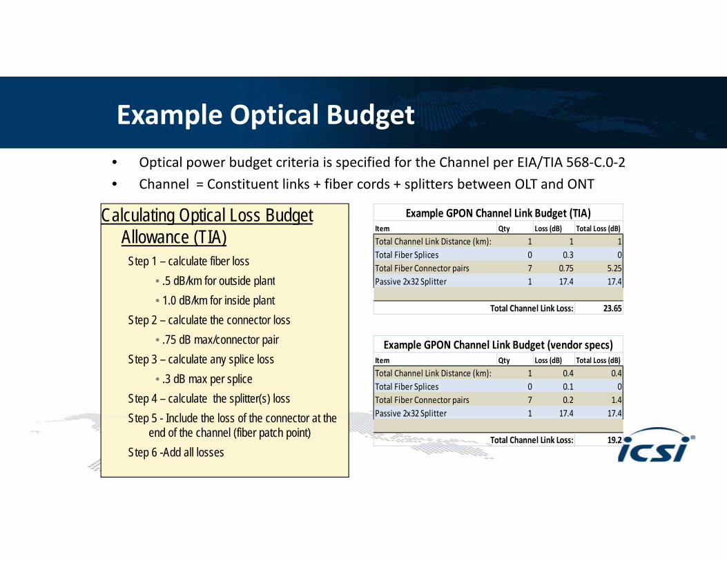
Example Optical Budget• Optical power budget criteria is specified for the Channel per EIA/TIA 568-C.0-2
• Channel = Constituent links + fiber cords + splitters between OLT and ONT
Calculating Optical Loss Budget Example GPON Channel Link Budget (TIA)Calculating Optical Loss Budget Allowance (TIA)
Step 1 – calculate fiber loss• 5 dB/km for outside plant
Item Qty Loss (dB) Total Loss (dB)
Total Channel Link Distance (km): 1 1 1Total Fiber Splices 0 0.3 0Total Fiber Connector pairs 7 0.75 5.25Passive 2x32 Splitter 1 17 4 17 4
Example GPON Channel Link Budget (TIA)
• .5 dB/km for outside plant• 1.0 dB/km for inside plant
Step 2 – calculate the connector loss• .75 dB max/connector pair
Passive 2x32 Splitter 1 17.4 17.4
Total Channel Link Loss: 23.65
Example GPON Channel Link Budget (vendor specs)Step 3 – calculate any splice loss
• .3 dB max per spliceStep 4 – calculate the splitter(s) lossStep 5 Include the loss of the connector at the
Item Qty Loss (dB) Total Loss (dB)
Total Channel Link Distance (km): 1 0.4 0.4Total Fiber Splices 0 0.1 0Total Fiber Connector pairs 7 0.2 1.4Passive 2x32 Splitter 1 17.4 17.4
a p e G O C a e udget ( e do specs)
Step 5 - Include the loss of the connector at the end of the channel (fiber patch point)
Step 6 -Add all losses
p
Total Channel Link Loss: 19.2

Singlemode Fiber Field Testing -Certification for Passive Optical LANs
• Tier 1 Testing is Required – Per TIA/EIA & IEC standards, Link segments should simply be tested visually and tested for loss.
Visual Inspections– Visual Inspections
Visually verify installed length as well as minimum end face scratches/debris and the polarity of any multi-fiber links
– Power meter/Light Source (PMLS)
PM/LS testing measures the end-to-end loss of the linkg
If attenuation is under the TIA optical budget allowance, it passes for commissioning
Use ANSI/TIA/EIA-526-7 Method A 1 One Reference Jumper method
Test Cabling Subsystem 1 links at 1310 nm.Test Cabling Subsystem 2 or 3 backbone links at 1310 and 1550 nm.Test channel at 1310 and 1550 nm (Attenuation between 13 and 28 dB for GPON Class B+) Use ANSI/TIA/EIA-526-7, Method A.1, One Reference Jumper methodTest channel at 1310 and 1550 nm (Attenuation between 13 and 28 dB for GPON Class B+).

Optional Tier II - Singlemode Fiber Field Testing
er (d
B)
beginning of fiber
reflective event(connector)
refle
cted
pow
e
non-reflectiveevent (splice)
fiber end
slope is fiber attenuation coefficient
Tier 2 Testing –Optical time domain reflectometer (OTDR) testing
• Optional per international standards bodies it is not required and does
time / distance (km)
• Optional per international standards bodies, it is not required and does not substitute for PMLS test
• Recommended for testing the outside plant and/or for troubleshooting
• Further details uniformity of cable attenuation, connector losses, y , ,connector/splice or trouble locations
• May be requested by the customer
F d t l fFundamentals ofPassive Optical LANPassive Optical LAN
Introduction to POL Actives and Management System

Brought to you by the Association for Passive Optical LAN
Founding Members:
www.apolanglobal.org

I t d ti t POL A tiIntroduction to POL Actives and Management Systemand Management System
Matt MillerMatt Miller
Principal Systems Engineer, CPOE, Leidos

Agenda• Components
– OLT• Standards
– IEEE vs. ITU– ONT– Video– DC Power
– Current– Development
• Future• Power Considerations• Management
– Centralized Management
– Wavelengths– Migration to 10G and Beyond
– Management Systems– Bandwidth Management– VLANs, QoS, LLDP and other
StandardsStandards

Components - OLT• OLT is head-end component
• Typically located in MDF or Data CenterTypically located in MDF or Data Center
• Manages connected ONTs
• Typically consist of:Typically consist of:– Management
– Switch Fabric
– Uplink Interfaces
– PON Interfaces
• Out-of-band Management

Components – Large OLT Models• Chassis-Based• Fully Redundant• Up to 112 PON PortsUp to 112 PON Ports• Thousands of ONTs• DC Powered
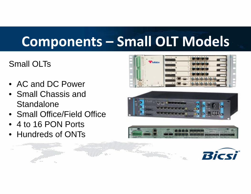
Components – Small OLT ModelsSmall OLTs
• AC and DC Power• Small Chassis and
Standalone• Small Office/Field Office• 4 to 16 PON Ports• Hundreds of ONTs

Components – OLT Uplinks• Standard Ethernet uplinks to core
l k ll l bl• Uplinks typically 1G or 10G pluggable optics
• VLANs trunked into uplink portss t u ed to up po ts
• Class C+ optics featureup to 32dB

Components – OLT PON Ports• From 4 to 112 PON ports per OLT
h ll• Each PON port typically serves 32 ONTs= Thousands of ONTs per OLT!p
• Typically SFP based
Cl C i f 32dB l b d• Class C+ optics feature 32dB loss budget

Components – OLT RedundancyTypically Redundant Sometimes Redundant
• Power
• Backplane
• PON Ports
• PON Cardsac p a e
• Management
O Ca ds
• Entire OLT
• Switch fabric
• UplinksUplinks
Components - ONT• ONT located close to the end user
b• Fiber input
• Variety of user interfaces availablea ety o use te aces a a ab e
• Provide PoE
• Consume ~7W power + PoE draw

Components – ONT Models• Large variety of ONTs
available
AC d DC
• Match interfaces to user needs:
Ethernet Ports with PoE• AC and DC power options
• Desk-mount, In-wall, d R k
– Ethernet Ports with PoE
– POTS Ports
– Coaxial Television
Wi Fiand Rack-mount
• Battery backup
– Wi-Fi
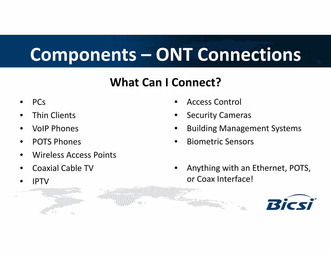
Components – ONT ConnectionsWhat Can I Connect?
• PCs
• Thin Clients
• VoIP Phones
• Access Control
• Security Cameras
• Building Management Systems• VoIP Phones
• POTS Phones
• Wireless Access Points
• Building Management Systems
• Biometric Sensors
• Coaxial Cable TV
• IPTV
• Anything with an Ethernet, POTS, or Coax Interface!
Components – ONT Compatibility• EPON and GPON are not compatible
ff f ll d• Different manufactures typically do not interoperate
• Within the standards, some manufacturers have additional features – especially EPONhave additional features – especially EPON
Components – ONT Security• ONT security design to assume the ONT is in
the hands of the adversarythe hands of the adversary
• ONT does not function without OLT
• Usually no management ports on ONT
ONT i ll i f OLT• ONT receives all programming from OLT

Power Considerations• ONTs report a loss of power or loss of service
b d• ONTs can be powered via AC or DC
• Battery backups for high availabilityatte y bac ups o g a a ab ty
• PoE for devices that need it

Components - Video
• Laser Transmitter – Electrical to Optical 1550nm Conversion
• EDFA – Amplifies Optical Signal up to 18 – 21dBm
• WDM – Combines Wavelengths

Components - Video• Laser Transmitter
• EDFA
• RF Nodesodes
• RFoG/two-way

Components – DC Power• Most OLTs use -48V DC Power
• Same power used in telcoSame power used in telco central offices
• Rectifiers required to convert qAC to DC
• Properly ground your equipment!

Components – DC Power• Redundant Inputs
• Redundant OutputsRedundant Outputs
• Redundant Rectifiers
• Fuse or Circuit BreakerFuse or Circuit Breaker Protection
• Network Managementg
• Basically an external power supply!

Centralized Management• ONTs Centrally Managed
h l• No physical ONT management ports
• Same concepts as traditional networkSa e co cepts as t ad t o a et o– VLANs
P E– PoE
– QoS
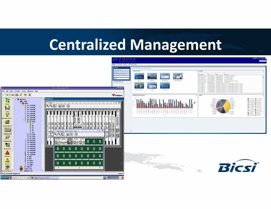
Centralized Management
Management Systems• Systems included standard CLI and
EMSEMS
• Application and Web/Mobile
h• GUI is more important in PON than legacy networksDensity is far greater!
• ONTs are an extension of the OLT
Profiles & Templates• Create a standard profile or template
for your servicesfor your services
• Apply that profile or template to many ONTs at once!ONTs at once!

Management Systems• Alarming and Notification
• Bandwidth Monitoring• Bandwidth Monitoring
• Central OLT & ONT Upgrades
• MAC Searches
• VLAN Member Reportsp

Bandwidth Management• Bandwidth Management is Built-in!
b d d h• Guarantee every user bandwidth– Set a committed rate
– Committed rates cannot exceed capacity of any link in the systemlink in the system
• Manage additional bandwidth as you desire– Set a peak rate

Bandwidth ManagementCommitted rates cannot
exceed capacity of any link in hthe system
Managing All The Same ThingsThe same things you manage today…
• VLANs
• PoE
• QoS
• LLDP
• Network Access Control

Standards – IEEE vs. ITU• ITU and IEEE have separate standards for PON
h d d h• Both standards use the same passive infrastructure (fiber & splitters)
• The only difference is the electronics

Popular Standards ComparisonEPON GPON
Standard IEEE 802.3ah ITU G.984
Speed 1Gbps Symmetrical 2.4Gbps Down / 1.2 Gbps Up
Framing Ethernet (mostly native) GEMS Encapsulation
Wavelengths 1490nm/1310nm 1490nm/1310nm
DynamicBandwidth
Optional Vendor Specific Built-in
Encryption Optional Vendor Specific AES-128 Downstream
102

Standards Timeline
19951996
1995 – APON Standard Introduced (155M)
IEEE ITU
199619971998199920002001
1999 – BPON Standard Approved (622M/155M)
2004 – EPON Standard Approved (1G)
200120022003200420052006
2003 – GPON Standard Approved (2.4G/1.2G)
2009 – 10G EPON Standard Approved (10G)
200620072008200920102011
2010 – XGPON1 Standard Approved (10G/2.5G)
103
2012 – Extended EPON Task Force Formed
2011201220132014

Converging Standards• IEEE and ITU working to converge standards in
future generationsfuture generations
• 10G EPON and XGPON use same PHYs
Future Standards• EPON/GPON Networks can co-exist on the same fiber
& splitters as 10G EPON/XGPON Networks& splitters as 10G EPON/XGPON Networks
• 10G EPON and XGPON use same PHYs
d k d d f• IEEE and ITU working to converge standards in future generations
• Next standards may combine multiple wavelengths in each direction for additional bandwidth

Complimentary WavelengthsEPON/GPON
1490nm Down / 1310nm Up1490nm Down / 1310nm Up
10G EPON/XGPON10G EPON/XGPON
1577nm Down / 1270nm Up
RF Video
1550nm Down1550nm Down

Migration to 10G2.5Gbps/1.25Gbps1490nm/1310nmGPON GPON ONT
OLTG O O
1
10G PON ONT10G PONOLT 10Gbps/10Gbps
1577nm/1270nm
• 10G PON can coexist on the same fiber as GPON• Bandwidths available as 10G Downstream and 10G/2 5G/1G Upstream
07107
107
• Bandwidths available as 10G Downstream and 10G/2.5G/1G Upstream• Uses same infrastructure/splitters as GPON• Casual migration – upgrade only the ONTs that you want

Thank You!
Questions?
Introduction to POL Actives and Management System
Matt Miller
Principal Systems Engineer, CPOE, Leidos

Fib H dli C tiFiber Handling, Connecting, Cleaning and TestingCleaning and Testing
Outline• Cable Twist and Swivels
• Connectors• Connectors
• Inspection & Cleaning
• Testing

Cable Twist• Fiber should never be subject to excessive twist. This results
in bending stress and increased attenuation.g
• When storing cable not on a reel, cable should lay flat in a figure 8 with curves larger than the minimum bend radius.g g
• When removing cable from a reel, roll cable off a free turning reel so it can turn. Never free-spin cable coming off a reel.reel so it can turn. Never free spin cable coming off a reel.
• Never pull fiber off the reel by sliding the cable over the flange of the reel This creates cable twist once the cable is straighten outthe reel. This creates cable twist once the cable is straighten out.
• Always use a break-away-swivel during installation
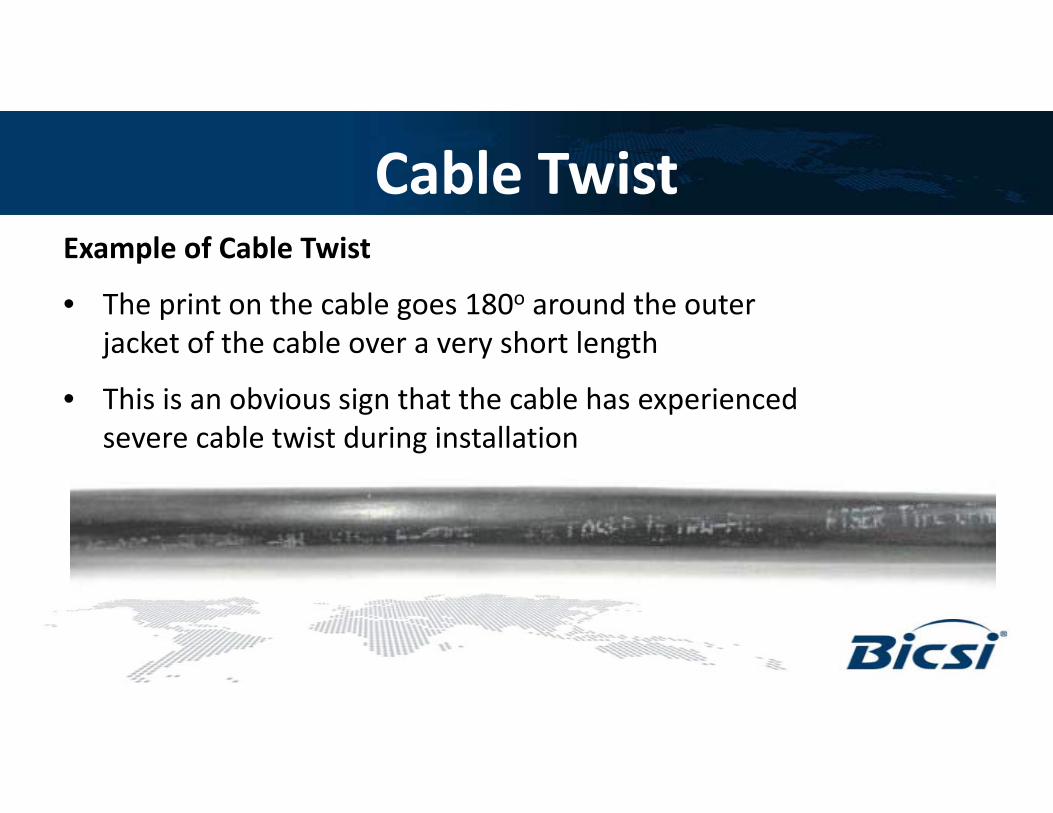
Cable TwistExample of Cable Twist
• The print on the cable goes 180o around the outerThe print on the cable goes 180 around the outer jacket of the cable over a very short length
• This is an obvious sign that the cable has experiencedThis is an obvious sign that the cable has experienced severe cable twist during installation

Break-Away Swivels• One end attaches to the pulling grip
and the other end attaches to the pulling ropepulling rope
• Designed to swivel to prevent cable twisting during installationg g
• Design to “break apart” at various pulling strengths in order to prevent damage to the cable due to exceeding th i t ll ti t il l dthe installation tensile load
• Can be purchased at various tensile loads
il l d f h b k i l h ld• Tensile load of the break-away-swivel should not exceed the installation tensile load of the cable
Fiber Connectors

Fiber Connectors
• SC & LC primarily used in PON
• Be aware of polish types , UPC and APC
’ l h l k• Don’t mix polish types in a link
• Use a precision fiber cleaver
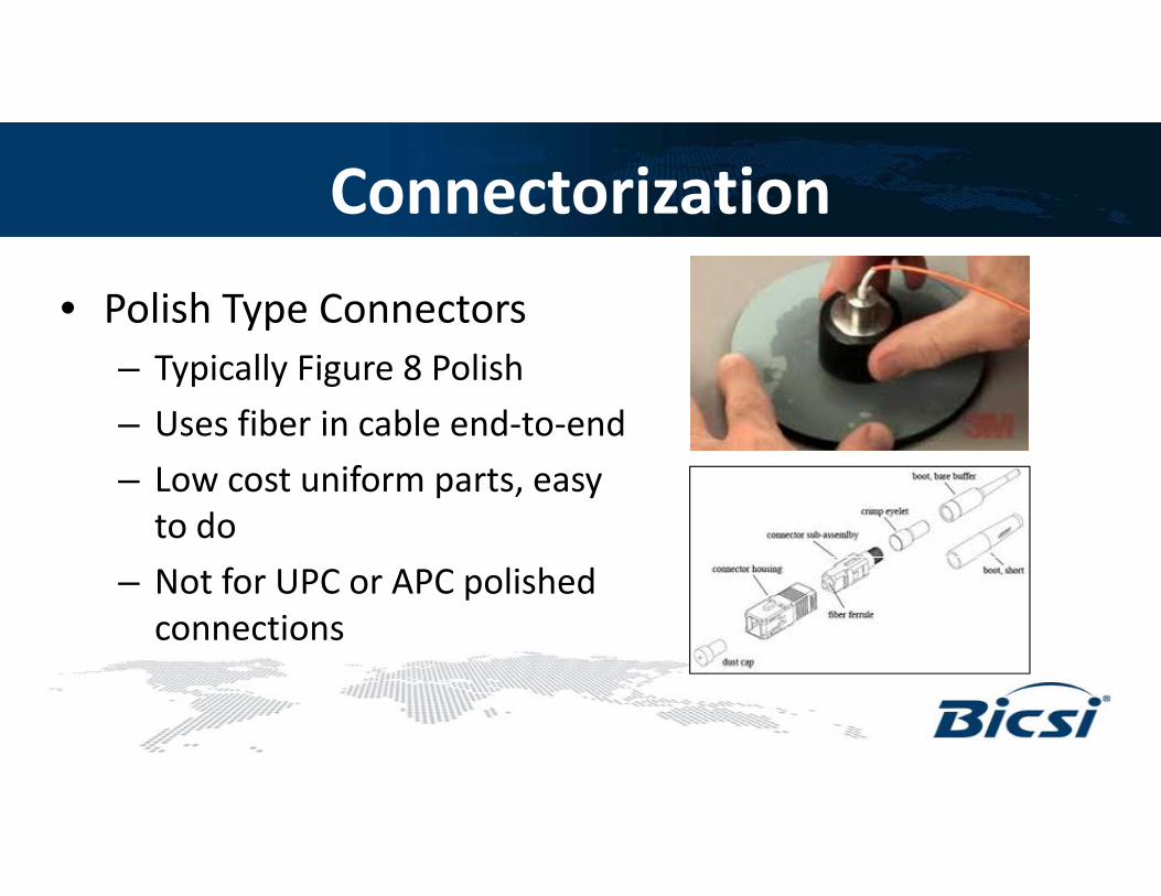
Connectorization
• Polish Type Connectors– Typically Figure 8 Polish
– Uses fiber in cable end-to-end
– Low cost uniform parts, easy to do
– Not for UPC or APC polished connections

Connectorization
• Prepolished ‘Cleave and Crimp’ connectors– Uses Index Matching Gel
Source: Corninginside the connector
– Some require a proprietary lk f
Source: Corning
toolkit to maintain uniformity
– Higher cost but less labor th li h d tthan polished type
– APC and UPC available !Source: FOA

Connectorization
• Splice On Connectors – Prepolished connectors
with fiber stub
– Fiber lab polished UPC or APC
Source: Corning
– Connector is spliced then built for strength
– Could be good at racks, cabinets and workstation
– Requires correct fusion splicer for connector
Connectorization
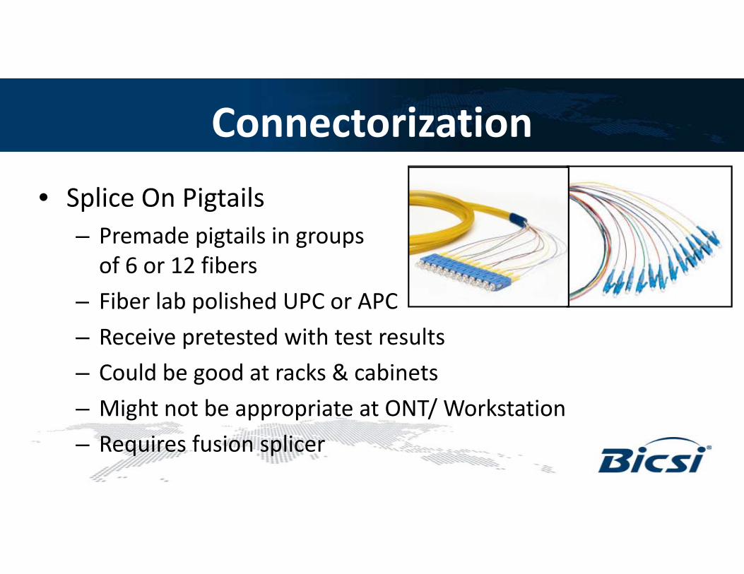
• Splice On Pigtails– Premade pigtails in groups
of 6 or 12 fibers
– Fiber lab polished UPC or APC
– Receive pretested with test results
– Could be good at racks & cabinets
– Might not be appropriate at ONT/ Workstation
– Requires fusion splicer
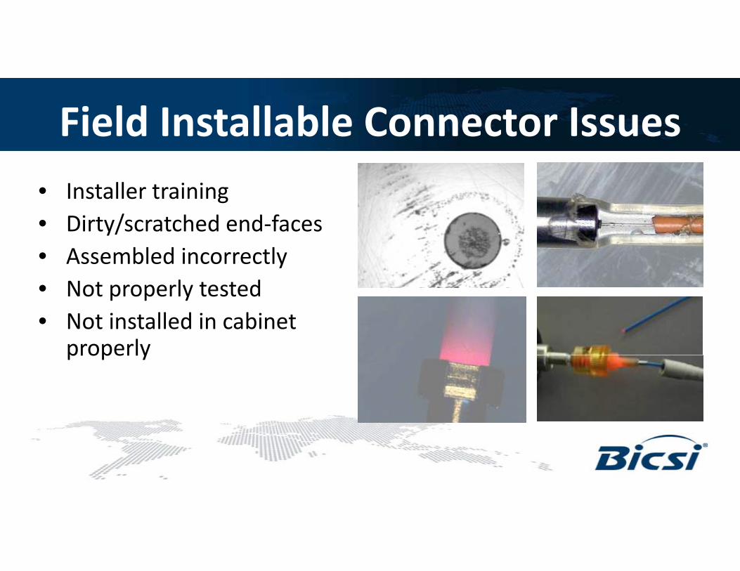
Field Installable Connector Issues• Installer training
Di / h d d f• Dirty/scratched end-faces• Assembled incorrectly• Not properly tested• Not properly tested• Not installed in cabinet
properlyproperly
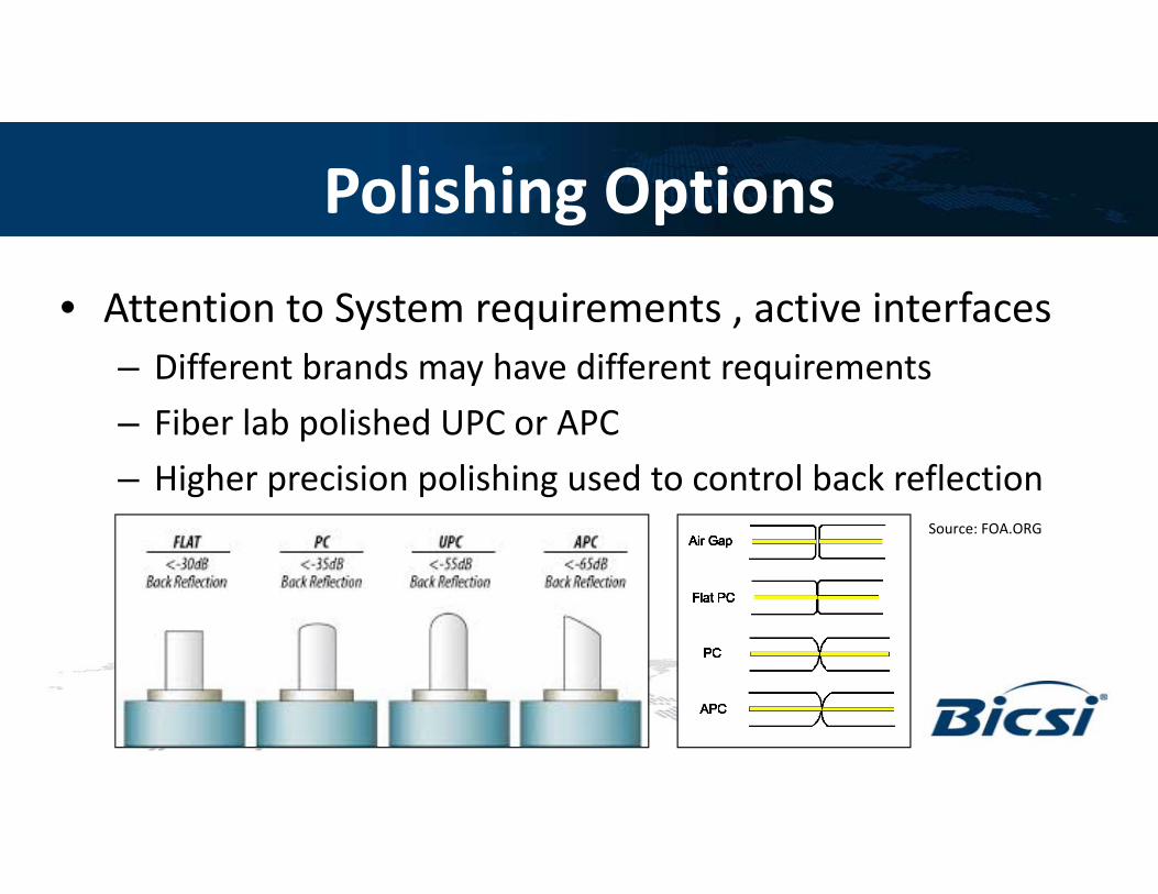
Polishing Options
• Attention to System requirements , active interfaces– Different brands may have different requirements
– Fiber lab polished UPC or APC
– Higher precision polishing used to control back reflectionSource: FOA.ORG

Back Reflectance

End Face Inspection & Cleaning

System Performance Factors
• Core diameter mismatch loss
• Concentricity and Ellipticity
• End face cleanliness

Fiber Inspection & Cleaning• 75%+ fiber network issues due to dirty or damaged connectors• Core alignment and physical contact controlled at factory• Core alignment and physical contact controlled at factory• Installers must confirm no contaminations before connecting• Dirt on fiber core dramatically affects signal performance• Dirt anywhere on end face is prone to break up and spread• Trapped dirt can permanently damage connector faces,
requiring replacement or re-polishing to restore performance• Irreparable damage to the active equipment could occur if the
connector is not replaced or cleaned prior to installing.
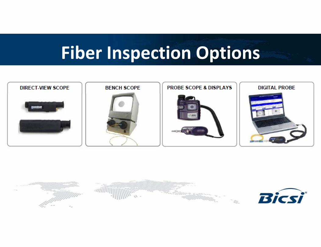
Fiber Inspection Options
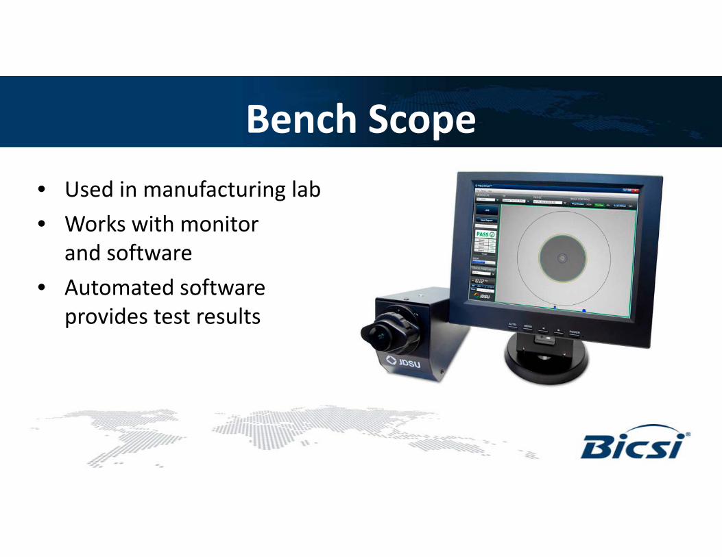
Bench Scope
• Used in manufacturing lab
• Works with monitor and software
d f• Automated software provides test results
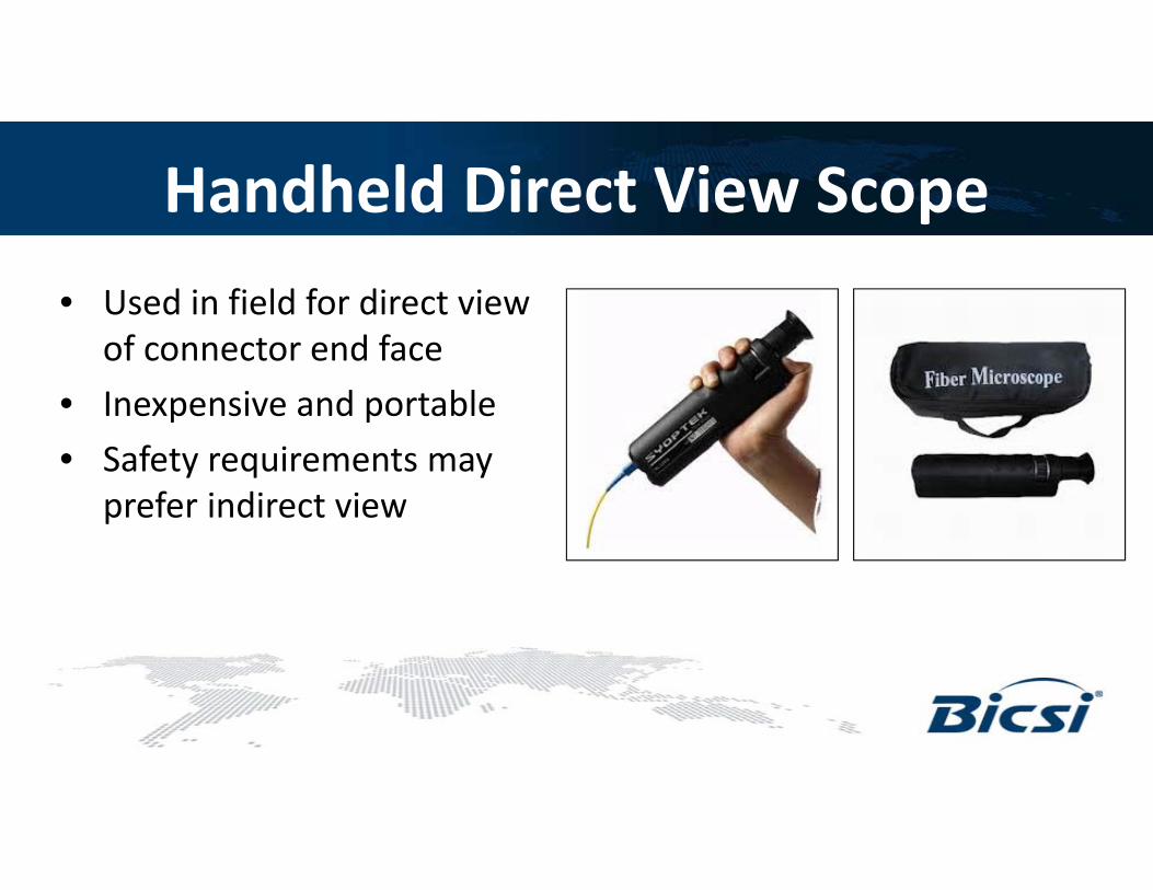
Handheld Direct View Scope
• Used in field for direct view f d fof connector end face
• Inexpensive and portable
f• Safety requirements may prefer indirect view

Probe Scopes and Displays
• Indirect view of end face i di lvia display
• Handheld and portable
lf d• Self contained or use with Laptop
S ft f P /F il• Software for Pass/Fail and Testing

Fiber Inspection and Cleaning
• Potential for damage is always present, even in i dnew equipment and components
• Avoid damage by initial contamination by first inspection and cleaningand cleaning
• This can add to initial cost, but overall cost at completion will be lowerwill be lower.
• Inspection results: reduce troubleshooting, highest network performance, prevents damage and covers investmentperformance, prevents damage and covers investment
Proactive Inspection
• Proactively create inspection & cleaning guidelines d f l iand formal requirements
• Consultants and owners can specify for starting at new constructionat new construction
• Contractors /integrators can include plan in bid and project documentsbid and project documents
• Any time connector is disturbed at new installation and used after at MAC’s and maintenanceand used after at MAC s and maintenance

Fiber End Face Should be ClearCommon types of contamination and defects include the following:
SINGLEMODE FIBER
A fiber end face should be free of any contamination or defects, as shown above
Source: JDSU

Reactive Cleaning
• Inspection only when there’s a problem is too late
• Permanent damage can occur
• Imbedded debris leaves pits , chips and defects in the fiber face
• Pits and defects cause back reflection and loss

Types of Contamination
• Dry Dust- particles , collect or bl d f iblow onto end faces or into bulkhead adapters
• Bonded Contamination is• Bonded – Contamination is adhering to oils, lotion, dried cleaning residuecleaning residue
• Embedded/mated – embedded dirt caused by connecting y gwithout cleaning

Contamination Spread
• When dirty connectors are d di i d d dmated dirt is moved and spread
across the fiber face
• Dirt larger than 5 microns breaks• Dirt larger than 5 microns breaks up and spreads
• Large bits create air gaps• Large bits create air gaps interfering with connection
• Small bits create pits and chipsSmall bits create pits and chips in the fiber
Cleaning
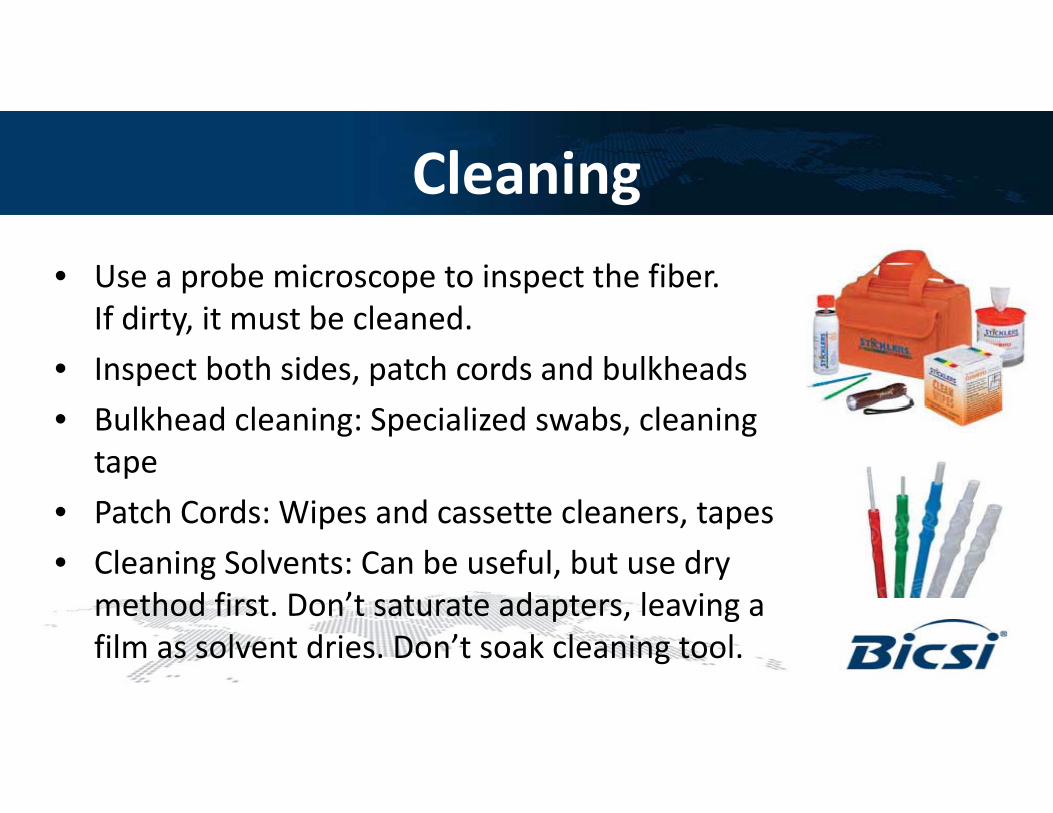
• Use a probe microscope to inspect the fiber. If di i b l dIf dirty, it must be cleaned.
• Inspect both sides, patch cords and bulkheads
lkh d l l d b l• Bulkhead cleaning: Specialized swabs, cleaning tape
P t h C d Wi d tt l t• Patch Cords: Wipes and cassette cleaners, tapes
• Cleaning Solvents: Can be useful, but use dry method first Don’t saturate adapters leaving amethod first. Don t saturate adapters, leaving a film as solvent dries. Don’t soak cleaning tool.

What Makes the Best Connection?
Three ruling factors direct the b i dbest connection and communication performance
• Precise core alignment• Precise core alignment
• Correct Physical contact at mated pairs Source: Cablinginstall commated pairs
• Untainted connector end face
Source: Cablinginstall.com

AT&T calls for a dry process first and if unsuccessful a wet process
This chart comes from AT&T Document ATT-TP-76461 titled “AT&T Fiber Optic Connector and Adapter Inspection and Cleaning Standards “ – in the public domain

IEC 61300-3-35IEC 61300-3-35 – Fiber Optic Connector Endface Visual and Automated Inspection,Endface Visual and Automated Inspection, an interoperability standard for connector manufacturers and users

IEC 61300-3-35Recommended Acceptance CriteriaAcceptance Criteria SM-UPC Connectors

IEC 61300-3-35Recommended Acceptance CriteriaAcceptance Criteria SM-APC Connectors

Both Sides of Mated Pair InspectedBoth sides of a mated pair must be inspected separately to be sure connection is free from contamination or damagebe sure connection is free from contamination or damage
Connector at the rear of a bulkhead can beConnector at the rear of a bulkhead can be viewed through the bulkhead

Testing

Testing
• Key is to isolate problems
• Splitters are passive, usually trouble free
k f• Look for issues at connectors and jumpers
B if di ti• Be aware if disconnecting before a splitter number of users on the channelof users on the channel
Testing
• Test in both directions
• Use an OLTS if available , otherwise standard loss tester at 1310 0r 1550
f k• If equipment uses 1490, Ok to test at 1550confirm splitters are pretested to save time; test cable linkstest cable links

Testing
• Testing with splitters: 3dB lost for each 1:2 split
• 568B.3 = max .75dB per mated pair
• Attenuation over distance in the cable run
• Bend insensitive cable can be helpful

OTDR Testing
• Not necessarily needed if links and actives test ll b i h b i dwell but might be required
• Can be useful in determining distance to microbends anomalies and bit errorsmicrobends, anomalies and bit errors
• Standard OTDR can be used on dark fiber at 1310 1550 or 14901310 1550 or 1490
• In service testers used to test active line on unused wavelengths – 1625 or 1650nmunused wavelengths 1625 or 1650nm

OTDR Testing (continued)
• If testing through splitters downstream OTDR d ’ i li fibdoesn’t recognize split fibers
• Events downstream from a splitter will show but which fiber is unknownbut which fiber is unknown
• Better to test upstream from user towards OLT
U t th h litt t t d 1 fib• Upstream through splitter treated as 1 fiber

OTDR Testing (continued)
• Be aware of splitter loss and other attenuation when testing
• Be aware of received power parameters at the ONT
• High received power is not uncommon
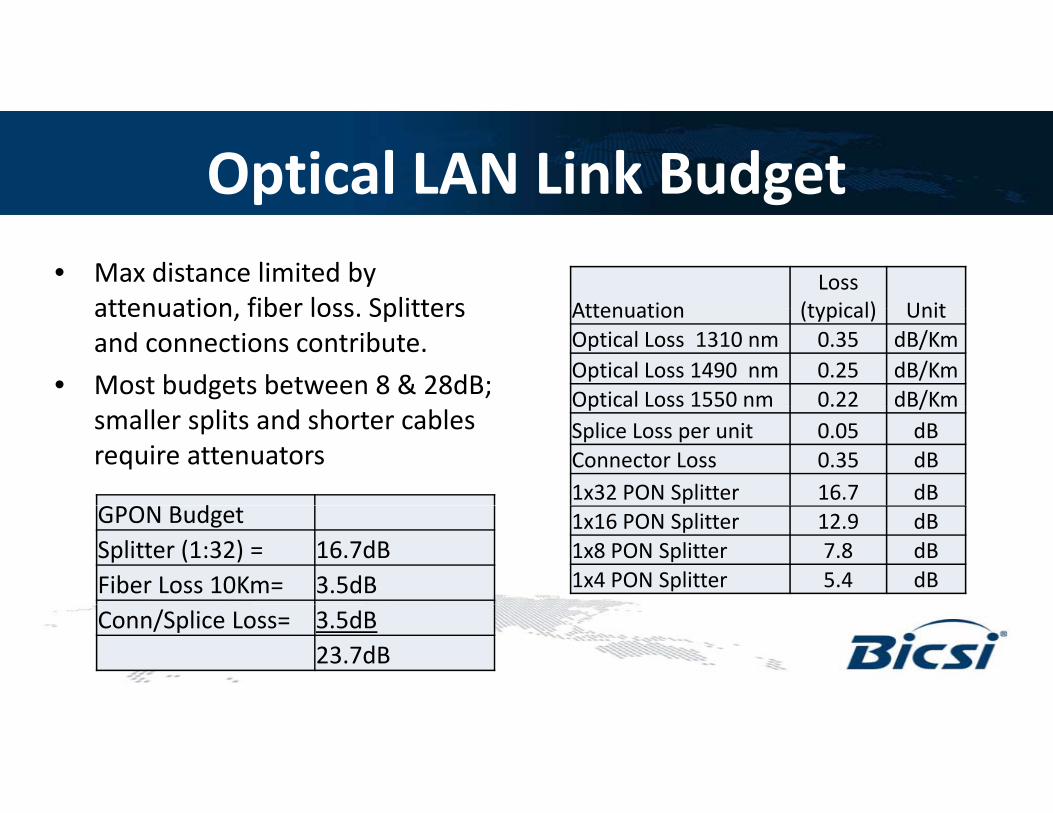
Optical LAN Link Budget• Max distance limited by
attenuation fiber loss Splitters AttenuationLoss
(typical) Unitattenuation, fiber loss. Splitters and connections contribute.
• Most budgets between 8 & 28dB;
Attenuation (typical) UnitOptical Loss 1310 nm 0.35 dB/KmOptical Loss 1490 nm 0.25 dB/KmOptical Loss 1550 nm 0.22 dB/Km
smaller splits and shorter cables require attenuators
p /Splice Loss per unit 0.05 dBConnector Loss 0.35 dB1x32 PON Splitter 16.7 dB
d 1x16 PON Splitter 12.9 dB1x8 PON Splitter 7.8 dB1x4 PON Splitter 5.4 dB
GPON BudgetSplitter (1:32) = 16.7dBFiber Loss 10Km= 3.5dBConn/Splice Loss= 3.5dB
23.7dB

Thank You!
Questions?