PASCO Mechanics Super Pulley Force Table - MyWeb at...
12
PASCO Mechanics Super Pulley Force Table ME-9447B Instruction Manual 012-13471A *012-13471* Super Pulley with Clamp (3) String Tie Assembly (3) Nylon Thread Force Table with 3 detachable legs Stacking peg Storage recess String Tie Assembly
Transcript of PASCO Mechanics Super Pulley Force Table - MyWeb at...

�
PASCO Mechanics
Super Pulley Force TableME-9447B
Instruct ion Manual012-13471A
*012-13471*
Super Pulley with Clamp (3)
String Tie Assembly
(3)
Nylon Thread
Force Table with 3 detachable legs
Stacking peg
Storage recess
String Tie Assembly

�
Super Pul ley Force Table
2
Table of Contents
Introduction . . . . . . . . . . . . . . . . . . . . . . . . . . . . . . . . . . . . . . . . . . . . . . . . . . . . . . . . . . . 3
About the Equipment . . . . . . . . . . . . . . . . . . . . . . . . . . . . . . . . . . . . . . . . . . . . . . . . . . . . 3
Assembly . . . . . . . . . . . . . . . . . . . . . . . . . . . . . . . . . . . . . . . . . . . . . . . . . . . . . . . . . . . . . 4
Experiment 1: Vector Addition . . . . . . . . . . . . . . . . . . . . . . . . . . . . . . . . . . . . . . . . . . . . . 7
Protractor . . . . . . . . . . . . . . . . . . . . . . . . . . . . . . . . . . . . . . . . . . . . . . . . . . . . . . . . . . . . 11
Technical Support . . . . . . . . . . . . . . . . . . . . . . . . . . . . . . . . . . . . . . . . . . . . . . . . . . . . . 12
Warranty, Copyright, and Trademarks. . . . . . . . . . . . . . . . . . . . . . . . . . . . . . . . . . . . . . 12

ME-9447B 012-13471A Introduct ion
� 3
Introduction
The Super Pulley Force Table includes equipment for vector addition experiments. You will also need masses, mass hangers, and a balance..
This manual contains descriptions of the included equipment and instructions for one experiment.
About the Equipment
The PASCO Model ME-9447B Force Table is used to physically demonstrate the addition of vectors using the concept of equilibrium (net force is zero). The vectors are forces supplied by the weight of masses (not included) that hang over pulleys. Masses hanging over pulleys placed at given angles are balanced by another mass over a pulley at another angle.
Among the features of the Force Table are:
• It is lightweight. (NOTE: Do not exceed 200 grams (0.20 kg) on each pulley.)
• It can be stored in a small space.
• The pulleys are low friction.
• The adjustable pulley clamps allow the string to be positioned close to the angle markings on the table, reduc-ing the parallax error in reading the angle.
• Equilibrium is achieved when the String Tie Assembly is centered in the middle of the Force Table.
The Force Table has three detachable legs that can be stored in the leg holders and clips on the underside of the table and the table includes spare String Tie Assemblies.
String Tie Assembly
The circular String Tie Assembly has two main parts: a clear disk through which the strings are tied and which is free to move from side to side over a short distance, and the outer part that snaps into the center of the Force Table. The label on the outer part has a ring that shows when the clear disk is centered.
Included Equipment Quantity Included Equipment Quantity
Force Table Assembly with Legs 1 String Tie Assembly 3
Super Pulley with Clamp 3 Spool of Thread 1
Required Equipment Recommended Equipment
Mass and Hanger Set (ME-8979) Mass Balance (see PASCO catalog)
Outer part snaps into the Force Table
Clear disk
Thread strings through this hole.
Ring on label

Super Pul ley Force Table Introduct ion
�4
• Assemble the Force Table
• Turn the Force Table upside down..Remove a leg from its storage clip and holder.
• Line up the leg screw with a threaded hole in the underside of the Force Table.
• Rotate the leg clockwise (left-to-right) until it is firmly attached to the table.
• Repeat for the other legs.
NOTE: Do not tighten the legs more than “finger tight”. They will be removed later for storage.
• Turn the Force Table right side up.
Attach the Pulleys
Attach three of the ME-9448B Super Pulley with Clamp to the edge of the force table.
Each clamp has two positions for holding the pulley yoke. You may want to move the pul-ley yoke to the lower position so that the top edge of the pulley can be more easily aligned with the top surface of the table. To do this, unscrew the thumbscrews on both sides of the clamp. Arrange the pulley yoke so the holes in the yoke are aligned with the lower threaded holes of the clamp. Replace the two thumbscrews but do not overtighten. NOTE: Each thumbscrew has a slotted head. If the thumbscrew is too tight, use a flat blade screwdriver to loosen it.
NOTE: If more than two forces are to be added, use the desired number plus one pulley and clamp for the equilibrium force.
Attach the Strings.
Get three pieces of string (thread), each about 30 centimeters long. Twist the ends of the strings together and thread the three strings through the hole in the middle of the clear plastic disk on the String Tie Assembly. Pull the ends of the threads through the hole and tie them together with an overhand knot so that the strings cannot be pulled back through the clear plastic disk
Insert the String Tie Assembly
The String Tie Assembly fits into the circular recess in the middle of the Force Table. The circular recess has two rectangular holes in the bottom and two shallow notches on its edge. The two short “legs” of the outer part of the
Storage clip
Threaded hole
Leg holder
Underside of Force Table
1. Remove a leg from its storage clip and holder.
2. Line up the leg screw with a threaded hole.
3. Rotate the leg into the threaded hole.
1.
2.3.
ME-9448B Super Pulley with Clamp
Clamp
Thumbscrew
Yoke
Storage recess
Stacking peg
String
Tie the ends together.

ME-9447B 012-13471A Introduct ion
� 5
String Tie fit into the rectangular holes in the recess. Align the short “legs” with the shallow notches. Insert one “leg” into one of the rectangular holes and then press down firmly on the other side of the String Tie until the other “leg” snaps into the other rectangular hole. NOTE: Press firmly. When the String Tie is correctly inserted, the top surface of the clear plastic disk will be flush with the surface of the Force Table.
To remove the String Tie from the Force Table, turn the Force Table over and press the two short “tabs” of the String Tie inward toward each other.
Setup
Arrange the strings over the pulleys. Attach a mass hangers to each string. NOTE: A string can be attached to a PASCO mass hanger by wrapping the string four or five times around the notch at the top of the mass hanger.
1. Insert one “leg” into one of the rectangular holes.
2. Press firmly to push the other “leg” into its hole.
String Tie
NOTE: Masses and mass hangers are not included.
Clamp shown with the pulley yoke in
the lower position..

Super Pul ley Force Table Introduct ion
�6
Storage
The Force Table may be stored with or without the ME-9448B Super Pulley with Clamp attached. To minimize the storage space needed for the Force Table, remove the legs by unscrewing them from the table. Store the legs in the leg holders and storage clips that are on the underside of the force table. The disassembled force tables can be stacked on top of each other. The three stacking pegs on the underside of one Force Table fit into the storage recesses on the top surface of a second Force Table to eliminate slipping.
Stacking peg
Storage recess
Vector Addi t ion
� 7
Vector Addition
Purpose
The purpose of this experiment is to use the force table to experimentally determine the force that balances two other forces. This result is checked by adding the two forces using their horizontal and vertical vector components, and by graphically adding the force vectors.
Theory
This experiment finds the resultant of adding two vectors by three methods: experimentally, by adding compo-nents, and graphically
NOTE: In all cases, the force caused by the mass hanging over the pulley is found by multiplying the mass by the acceleration due to gravity, 9.8 m/s2.
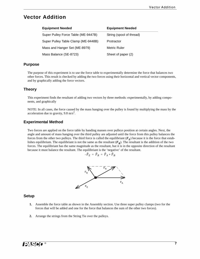
Experimental Method
Two forces are applied on the force table by handing masses over pulleys position at certain angles. Next, the angle and amount of mass hanging over the third pulley are adjusted until the force from this pulley balances the forces from the other two pulleys. The third force is called the equilibriant (FE) because it is the force that estab-lishes equilibrium. The equilibriant is not the same as the resultant (FR). The resultant is the addition of the two forces. The equilibriant has the same magnitude as the resultant, but it is in the opposite direction of the resultant because it must balance the resultant. The equilibriant is the ‘negative’ of the resultant.
Setup
1. Assemble the force table as shown in the Assembly section. Use three super pulley clamps (two for the forces that will be added and one for the force that balances the sum of the other two forces).
2. Arrange the strings from the String Tie over the pulleys.
Equipment Needed Equipment Needed
Super Pulley Force Table (ME-9447B) String (spool of thread)
Super Pulley Table Clamp (ME-9448B) Protractor
Mass and Hanger Set (ME-8979) Metric Ruler
Mass Balance (SE-8723) Sheet of paper (2)
FE– FR FA FB+= =
FA
FE
FB
FR
�8
3. Hang the following masses over two of the super pulleys and clamp the pulleys at the given angles.
Procedure (Experimental Method)
By trial and error, find the angle for the third super pulley clamp and the mass that must be suspended over the pul-ley so that its weight will balance the forces exerted on the strings by the other two masses. This third force is called the equilibriant (FE) because it establishes equilibrium. The equilibriant is the negative of the resultant.
Record the mass and angle for the third pulley to put the system into equilibrium into Table 1.1.
To test whether the system is in equilibrium, use the following criteria.
Method of Finding Equilibrium
The clear disk will be centered in the String Tie when the system is in equilibrium. Pull the clear disk slightly to one side and let it go. Check to see that the disk returns to the center. If not, adjust the mass and/or the angle of the super pulley clamp until the disk always returns to the center when pulled slightly to one side.
Analysis
To theoretically determine what mass should be suspended over the third pulley, and at what angle, calculate the magnitude and direction of the resultant by the component method and the graphical method. The equilibriant (FE) will have the same magnitude, but it will be opposite in direction. In other words, the direction will be 180° from the direction of the resultant.
Component Method
On a separate sheet of paper, add the vector components of Force A and Force B to determine the magnitude of the equilibriant. Record the components Rx and Ry in Table 1.2. Use trigonometry to find the direction of the equilib-riant (remember, the equilibriant is exactly opposite in direction to the resultant.) Record the results in Table 1.2.
Graphical Method
On a separate sheet of paper, construct a tail-to-head diagram of the vectors of Force A and Force B. Use a metric ruler and protractor to measure the magnitude and direction of the resultant. Record the results in Table 1.2. Remember to record the direction of the equilibriant as opposite in direction to the resultant..
Rx = ______________ Ry = ______________
Table 1.1:
Force Mass Angle
FA 50 g (0.050 kg) 0°
FB 100 g (0.100 kg) 120°
FE
Table 1.2:
Equilibriant (FE)
Method Magnitude Direction
Experimental
Component
Graphical

� 9
Question
How do the theoretical values for the magnitude and direction of the equilibriant compare to the actual magnitude and direction?

�10

� 11
Appendix
The protractor on this page is a version of the degree scale on the top surface of the Force Table. It can be dupli-cated, trimmed, and used as an overlay on the Force Table for drawing and tracing the string positions.
� ����
����
���
���
����
���
���
���
�
���
�����
��������������
���
������
�����
�����
������
���
������
��� ���
���
��
�
����
���
�
���
��������
���
�����
������
���
���

�12
Technical Support
For assistance with any PASCO product, contact PASCO at:
For the latest revision of this Instruction Manual, visit the PASCO web site at www.pasco.com and enter ME-9447B into the Search window.
Limited Warranty For a description of the product warranty, see the PASCO catalog. Copyright The PASCO scientific 012-13471A Super Pulley Force Table Instruction Manual is copyrighted with all rights reserved. Permission is granted to non-profit educational institutions for reproduction of any part of this manual, providing the reproductions are used only in their laboratories and classrooms, and are not sold for profit. Reproduction under any other circumstances, without the written consent of PASCO scientific, is prohibited. Trademarks PASCO and PASCO scientific are trademarks or registered trademarks of PASCO scientific, in the United States and/or in other countries. All other brands, products, or service names are or may be trademarks or service marks of, and are used to identify, products or services of, their respective owners. For more information visit www.pasco.com/legal.
Address: PASCO scientific10101 Foothills Blvd.Roseville, CA 95747-7100
Phone: 916-786-3800 (worldwide)800-772-8700 (U.S.)
Fax: (916) 786-7565
Web: www.pasco.com
Email: [email protected]

![OPTIKRIK TENSION GAUGES - optibelt.com · Belt section Diameter of the small pulley [in] Standard (wrapped) SUPER X-POWER SUPER TX RED POWER 3 HVAC POWER BLUE POWER Initial installation](https://static.fdocuments.net/doc/165x107/5d4dcdd988c99357088bc8c9/optikrik-tension-gauges-belt-section-diameter-of-the-small-pulley-in-standard.jpg)